

Page 1
Rapid Eye Hybrid LT: Quick Setup
SERIALPORT 2
SERIALPORT 1 VGA
TELCO
USB USB
LAN
IN
OUT
NOT
USED
1 2 3 4
5
6 7 8
SPOT
MONITOR
VIDEO
INPUTS
COMMON
SYS FAIL
SYS GOOD
FAULT
RELAY
28V, 3A
MAX
1GGGG234
CONTROL
OUTPUTS
SERIAL
PORT 3
SERIAL
PORT 4
1G G G G234
5G G G G678
ALARM INPUTS
ON/OFF
POWER
115-230V~
50/60 Hz
5-3A
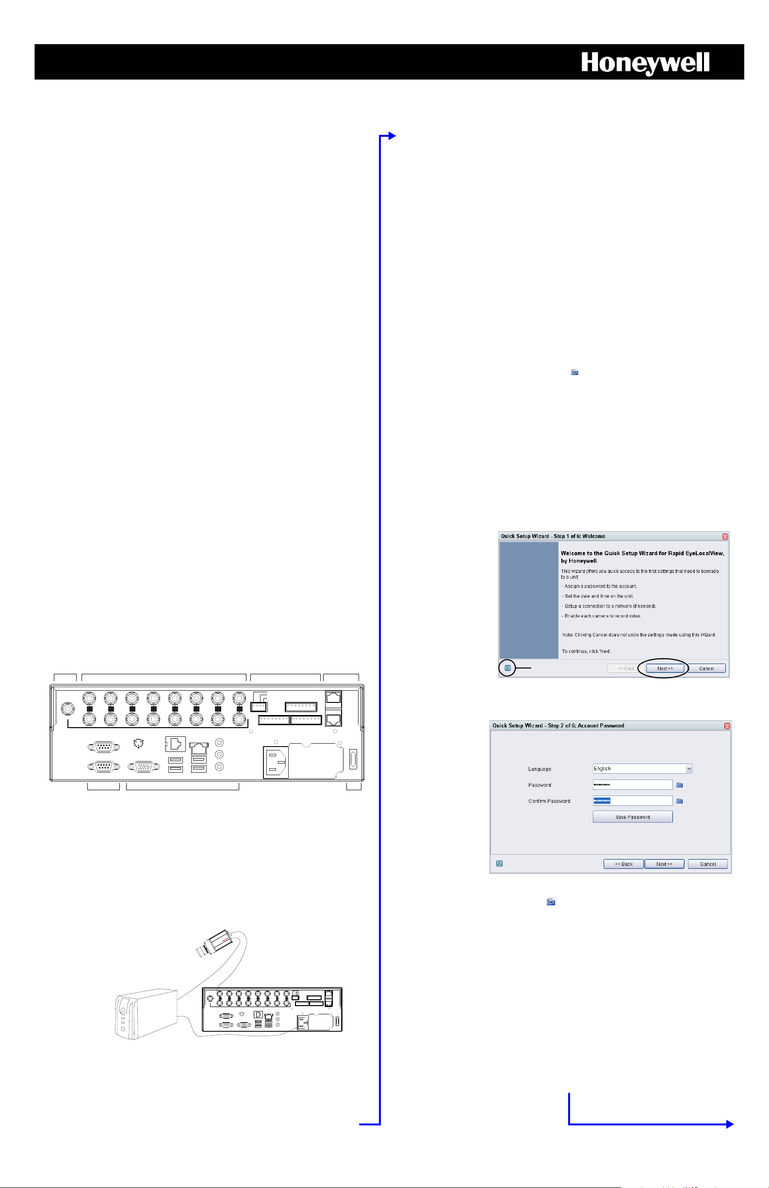
Video inputs and outputs, for analog cameras
(LT units can have 4 or 8 inputs/outputs)
Serial ports
3 and 4
Communication ports, including VGA for
a monitor, USB for a USB mouse and LAN
for connecting to the network
Power
switch
Serial ports
1 and 2
Alarm and control
connectors
Spot monitor
video output
Rapid Eye Hybrid LT 8-Channel unit rear panel connections
SERIALPORT2
SERIALPORT1 VGA
TELCO
USB USB
LAN
IN
OUT
NOT
USED
1 2 3 4 5 6 7 8
SPOT
MONITOR
VIDEO
INPUTS
COMMON
SYSFAIL
SYSGOOD
FAULT
RELAY
28V,3A
MAX
1G G G G23
4
CONTROL
OUTPUTS
SERIAL
PORT3
SERIAL
PORT4
1GGGG234
5G G G G678
ALARM INPUTS
ON/OFF
POWER
115-230V~
50/60Hz
5-3A
VIDEO connector on an
analog camera to the VIDEO
INPUT on the DVR.
IP cameras are connected
through the Local Area
Network (LAN) connection.
Connect power supply
from camera to UPS
Connect power
source to UPS,
then connect
power supply from
UPS to DVR
Help
The Quick Setup Wizard
lists which actions can be
taken during its use. The
? button (Help) can be
used, as needed. Click
Next to advance to the
next step. You can return
to a previous step by
clicking Back.
To change the
language in
LocalView, click the
Language dropdown arrow and
select a language
from the list that
appears.
Overview
This document shows how to:
• Connect essential hardware to a Rapid Eye Hybrid LT DVR.
• Make basic settings using the unit’s Quick Setup Wizard.
Note More detailed Rapid Eye documentation is available on the
Documentation CD included with your DVR.
After
Using the
Quick
Setup
Wizard
Context-sensitive Help for LocalView: available by clicking the ? icon in the
upper right corner and then clicking the item you want help with.
The documentation CD that comes with the unit contains other helpful user
guides. The System Admin Guide and Remote View Guide describe using
the Admin and View applications. For hardware and installation information,
see the Rapid Eye Hybrid LT Installation Guide.
1 Connecting Hardware
Camera(s), Monitor and Mouse
•One or many video cameras and/or PTZ domes (IP and analog).
•A PC monitor.
•A computer mouse with a USB connector, included.
•A computer keyboard, not included.
IP Camera(s)
Rapid Eye Hybrid LT V10.1 DVRs support up to 4/8 Honeywell equIP® V2,
®
equIP
H.264, equIP® 1080p, equIP® Wide Dynamic Range IP,
Performance IP, and/or HD3/4 IP cameras on Hybrid LT V10.1 units. Some
ONVIF IP cameras are also supported (see http://
www.security.honeywell.com/hota for a complete list of supported IP
cameras). Rapid Eye Hybrid LT V10.0 units do not support Honeywell
Performance IP, equIP
IP cameras, and support fewer IP channels if Local Monitoring (LocalView) is
enabled. Refer to the Rapid Eye System Administrator Guide included on the
documentation CD for information on enabling or disabling Local
Monitoring.
Refer also to the Rapid Eye System Administrator Guide for a complete list of
IP cameras supported (and their supported features) by Rapid Eye Hybrid
LT V10.1 and V10.0 DVRs.
Connect the IP cameras to the Local Area Network (LAN) where your unit is
installed. See the documentation that was included with the camera to install
and connect the camera to the Local Area Network. See 12 IP Camera
Discovery and Setup for information on setting up UP cameras for use in
your Rapid Eye Hybrid LT system.
®
1080p, equIP® Wide Dynamic Range IP, and ONVIF
3 The Start-up Sequence
Recommended Powerup Sequence
1. Turn on cameras (analog and IP) and other hardware, connected to the
DVR. Honeywell recommends that cameras be powered up before the
Rapid Eye unit starts up, so they are automatically detected by the DVR.
2. Press the power switch on the back of the unit.
Note When the unit powers up, you will have the option of booting the
unit from either the primary or recovery operating system. Use
the primary OS boot-up unless an OS recovery is required. The
primary boot-up is the default and will be run automatically after
5 seconds. See the Rapid Eye Hybrid LT Installation Guide or call
technical support for more information.
3. Display the Login window on the connected monitor. After poweringup, wait until video is shown. Move the mouse or press a key on the
keyboard to display the Login window.
4 Logging On
To log on, enter Administrator in the User Name text box if it is not
already entered. Click the icon ( ) to open the virtual keyboard and enter
the user name. Click OK to confirm the name and close the keyboard. Leave
the Password text box empty; a password can be added to the local
Administrator account later. Click OK to logon.
5 Welcome to LocalView
When the Welcome window appears, click Quick Setup to start the Quick
Setup Wizard.
Select the Do not show this dialog again option if you don’t want to use
Quick Setup Wizard again, the next time you start LocalView.
6 The Quick Setup Wizard
Analog Camera(s)
Connect each camera to a VIDEO INPUT connector at the rear of the Rapid
Eye Hybrid LT unit.
Connecting a Monitor, Mouse and Keyboard
Connect a VGA monitor to the VGA port at the rear of the unit. If possible,
connect a USB keyboard (not included) to the unit; if the keyboard has two
USB connectors, connect each one. Connect the supplied USB mouse, or
your own mouse, to use with LocalView.
2 Powering the Unit and the Cameras
7 The Administrator Password
Honeywell recommends that you set a password for the Administrator
account to prevent tampering with the unit’s settings and the stored video.
Click the keyboard icon ( ) to open the virtual keyboard and enter the
password. Do not use double-quotes (“) in the password.
For more information, use the LocalVIEW Help.
Using an Uninterruptible Power Supply
Honeywell recommends using an uninterruptible power supply (UPS) for the
Rapid Eye Hybrid LT DVR and the cameras. Powering the cameras and unit
from a UPS ensures that the Rapid Eye Hybrid LT can continue to record
video during a power outage. If you need to monitor video during a power
outage, consider a UPS for the monitor as well.
8 Setting the Date, Time and Time Zone
Time Zone Selection and Manually Setting Date and Time
It is important to indicate the Time Zone in which the Rapid Eye Hybrid LT
unit is installed, so that the date and time of the video are correct. Click Set
Date and Time to manually change the time and date settings.
Option: Automatic Time and Date
On a network, the date and time of a Rapid Eye Hybrid LT DVR can be set to
Automatic, using SNTP. Your network administrator will know if SNTP is in
use, and what to enter into the Primary SNTP Server text box that becomes
available after the Automatic option is selected.
For the next step in this Wizard, see over.
Page 2
Rapid Eye Hybrid LT Unit: Quick Setup
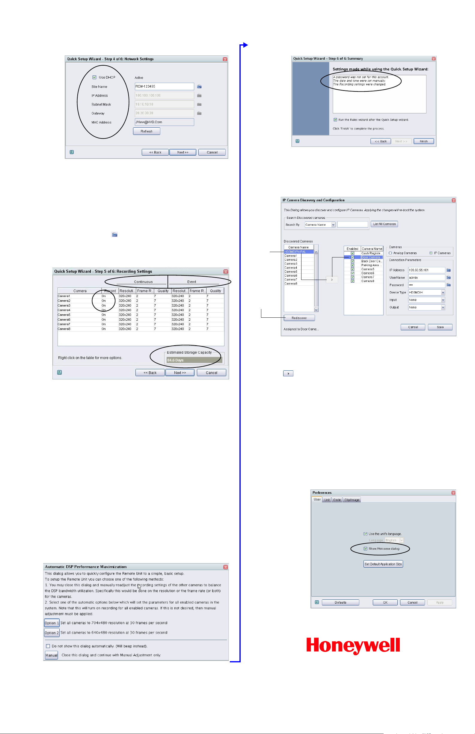
Select a
Discovered
camera and
click the
arrow (>) to
assign it to
the selected
video channel
on the rapid
Eye unit
Click
Rediscover
to refresh the
list of
discovered IP
cameras.
The Quick Setup button
(and the Welcom e to
LocalView window) are
hidden when the Do not
show this dialog again
check box is selected (see
5 Welcome to LocalView).
To make the Quick Setup
button available again,
select the Show Welcome
Panel option in the
LocalView User
Preferences window (select
the drop-down arrow next
to the logged in user name
in the top right corner). You
can then run the Quick
Setup Wizard the next time
you log on to LocalView.
9 Network Settings
Standalone LocalView-Only Units
If the Rapid Eye Hybrid LT unit is not connected to a network, leave the fields
blank in step 4 of the Quick Setup Wizard and then click Next.
Using a Network Connection
Enter a name for the DVR using the Site Name text box. Your network
administrator will know whether DHCP should be used, or if a network
address for the unit needs to be manually input. For Network Address
Translation (NAT, the use of one IP address for many units), enter the
Internet router’s inside IP
Click the keyboard icon ( ) to open the virtual keyboard for each one of
these fields and enter the appropriate network values.
11 The Report of the Wizard’s Activity
Before finishing the Quick Setup Wizard, you have the option of running the
Rules Wizard. The Rules Wizard is used to automate Event recording and is
explained in the LocalView online Help. Click Finish to close the Quick Setup
Wizard.
12 IP Camera Discovery and Setup
address into the Gateway text box.
10 Recording Settings
Recording Continuous Video
Analog
Cameras
Connected analog cameras are detected automatically when the unit is
powered up or re-booted. Cameras are listed in a table. To record video, click
the cell in the Record column for a camera and select On. Video from that
camera is recorded using the settings in the Continuous Resolution, Frame
Rate and picture Quality columns. Click a cell to change the Resolution,
Frame Rate or Quality values. See 12 IP Camera Discovery and Setup for
more information on setting up and using IP cameras in the Rapid Eye Hybrid
LT system.
Event Video Recording
Set the Event recording settings to higher values than those for Continuous
recording. While monitoring video, an operator can then increase the video
recording settings, as needed.
Note IP cameras can only adjust the Frame Rate setting for Event
recording. The Resolution and Quality settings are the same for
Continuous and Event recording.
IP cameras must be added after the Setup Wizard has completed. Select
Cameras on the Configuration tab of the leftmost pane of the LocalView
window. Click the Camera Configurations button.
The IP Camera Discovery and Configuration screen opens and lists autodiscovered IP cameras. Select a discovered IP camera and click the arrow
( ) to assign it to the selected Rapid Eye channel. Channels that have an
IP camera assigned can be switched back to analog by selecting the Analog
Cameras radio button for that channel.
Confirm and modify (if needed) the IP camera’s Connection Parameters (IP
Address, UserName, Password, and so on). Click Save. If one or more
cameras have been changed from analog to IP, or from IP to analog, the Save
button becomes a Save & Reboot button. You will be warned that saving
these changes requires the unit to reboot. Make all of the camera changes
necessary (to avoid rebooting the DVR unit multiple times), then click Save &
Reboot to reboot the unit.
The IP cameras can now be viewed and recorded, once the unit has booted
back up. Now that the IP cameras have been assigned to a video channel, go
to the Recording Settings window to set up the recording resolution, frame
rate and quality settings for the IP cameras that you have assigned to the
Rapid Eye unit.
Access to the Quick Setup Wizard
Optimization
When setting values for Continuous recording, monitor the Estimated
Storage Capacity value to ensure that the length of the video archive meets
the needs of your organization.
On DVRs with many cameras that are inputting very high values on every
camera, suggestions for maximizing the performance of the unit can be
produced (see the image below). There can be more than the two Option
buttons to select, depending on the number of cameras you are using.
© 2013 Honeywell International Inc. All rights reserved. No part of this publication may be
reproduced by any means without written permission from Honeywell. The information in this
publication is believed to be accurate in all respects. However, Honeywell cannot assume
responsibility for any consequences resulting from the use thereof. The information contained
herein is subject to change without notice. Revisions or new editions to this publication may be
issued to incorporate such changes.
www.honeywellvideo.com
+1.800.323.4576 (North America only)
https://www.honeywellsystems.com/ss/techsupp/index.html
Document 800-07768V4 Rev A 01/2013
 Loading...