

Page 1
RAEGuard 2 PID
___________________________________
User Guide
___________________________________
P/N: H-D03-4001-000
Rev M February 2018
Page 2

RAEGuard 2 PID User’s Guide
Contents
Section 1: RAEGuard 2 PID User’s Guide
1 General Information ............................................................ 6
2 General Specifications ......................................................... 8
2.1 RAEGuard 2 PID Specifications ........................... 8
2.2 Proper Product Disposal At End Of Life ............... 9
3 Operation ........................................................................... 10
4 Physical Description .......................................................... 11
5 Physical Dimensions ......................................................... 11
6 Installation and Access Instructions .................................. 12
6.1 Mounting ............................................................. 12
6.2 Instrument Disassembly ...................................... 14
6.3 Electrical Wiring ................................................. 15
6.4 Wiring Procedure ................................................. 16
6.5 Earth Grounding Instructions .............................. 17
6.5.1 External Earth Grounding ................................ 17
6.5.2 Internal Earth Grounding ................................. 17
6.5.3 Finished Grounding Wires .............................. 18
6.6 Alarm Contact Setup ........................................... 18
7 Display And User Interface ............................................... 20
7.1 User Interface ...................................................... 20
7.2 Magnet Key ......................................................... 20
7.3 Using The Magnet Key ....................................... 21
7.4 System Initialization ............................................ 21
7.5 Reading Display .................................................. 21
7.6 Instrument Status Display .................................... 22
8 Navigating Settings ........................................................... 23
9 Programming Menus ......................................................... 27
Zero/Fresh Calibration......................................................... 27
Meas. Unit* ...................................................................... 27
High Alarm ....................................................................... 27
Temp. Unit ........................................................................ 27
Span Calibration ................................................................. 27
Meas. Range* ................................................................... 27
Low Alarm ........................................................................ 27
1
Page 3

2
RAEGuard 2 PID User’s Guid e
Language .......................................................................... 27
Set Span Value ................................................................. 27
Meas. Gas* ....................................................................... 27
Ext. Alarm Delay* ............................................................ 27
Pump Duty (%)* ............................................................... 27
Calibration Type* ............................................................. 27
Pump Cycle(s)* ................................................................ 27
Calibration Gas* ............................................................... 27
Pump Status* .................................................................... 27
Bus Baudrate .................................................................... 27
Analogout 4mA ................................................................ 27
Analogout 20mA ................................................................ 27
Unit ID .............................................................................. 27
LCD Contrast .................................................................... 27
LCD Backlight .................................................................. 27
Change Password* ............................................................ 27
9.1 Entering Programming Mode .............................. 28
9.2 Calibration ........................................................... 29
9.3 Measurement (Advanced Mode) ......................... 32
9.4 Alarm Setting ....................................................... 35
9.5 Monitor Setup ...................................................... 37
10 Calibration .................................................................. 43
10.1 Zero Calibration ................................................... 44
10.2 Span Calibration .................................................. 46
11 Alarm Signal Summary .............................................. 48
12 Maintenance ............................................................... 50
13 DigiPID Sensor Module Replacement ....................... 50
14 Troubleshooting .......................................................... 52
SECTION 2: DigiPID User’s Guide
SAFETY INSTRUCTIONS ..................................................... 54
15 Read Before Operating ............................................... 55
15.1 DigiPID Marking ................................................. 56
15.2 Operation Area and Conditions ........................... 57
15.2.1 Hazardous Areas classified by Zones ............ 57
15.2.2 Hazardous Areas classified by Divisions ...... 57
Page 4

3
RAEGuard 2 PID User’s Guid e
15.3 Instruction For Safe Use ...................................... 57
15.4 Use In Hazardous Areas ...................................... 58
15.5 Year of manufacture ............................................ 58
15.6 Specifications ...................................................... 59
16 General Informatio n ................................................... 60
17 Grounding (Earth Connection) ................................... 61
18 Physical Description ................................................... 62
19 Sensor Parts And Dimensions .................................... 63
20 Operating the Sensor Module ..................................... 64
20.1 Preparing The Sensor For Use ............................. 64
21 Using The Sensor Module .......................................... 65
21.1 Gas Flow Routing Connection ............................ 65
21.2 Sensor Module Calibration .................................. 66
21.3 Maintenance And Calibration .............................. 68
21.4 Replacing the Lamp And Filter ........................... 68
22 Replacing The Sensor’s Teflon UV Shield ................ 70
23 Sensor & Lamp Cleaning/Replacement ..................... 73
23.1 Cleaning The PID Sensor .................................... 73
23.2 Cleaning The Lamp Housing Or
Changing The Lamp ............................................ 74
23.3 Cleaning The Instrument ..................................... 75
23.4 Ordering Replacement Parts ................................ 75
23.5 Special Servicing Note ........................................ 75
24 Electronic Waste Disposal .......................................... 76
25 Appendix A: Range, Sensor and
Related Configuration ................................................ 77
26 ModBus/RS-485 Information ..................................... 77
27 Appendix B: Controlled Section ................................ 79
27.1 Scope ................................................................... 79
27.2 Contents ............................................................... 79
27.3 Scope ................................................................... 81
27.4 Responsibility ...................................................... 81
27.5 Contents ............................................................... 81
28 Technical Support ....................................................... 89
29 Honeywell Analytics Contacts ................................... 89
Page 5

4
RAEGuard 2 PID User’s Guid e
© Honeywell International ©2018. All Rights Reserved.
This document is the confidential and proprietary information of
Honeywell. Reproduction and distribution of these materials without
the express written consent of Honeywell is strictly forbidden.
While this information is presented in good faith and believed to be
accurate, Honeywell disclaims the implied warranties of
merchantability and fitness for a purpose and makes no express
warranties except as may be stated in its written agreement with and
for its customer.
In no event is Honeywell liable to anyone for any direct, special, or
consequential damages. The information and specifications in this
document are subject to change without notice.
These commodities, technology, or software were exported from the
United States in accordance with the Export Administration
Regulations. Diversion contrary to U.S. law prohibited.
This product may contain or be derived from materials, including
software, of third parties. The third-party materials may be subject to
licenses, notices, restrictions and obligations imposed by the licensor.
The licenses, notices, restrictions and obligations, if any, may be
found in the materials accompanying the product, in the documents or
files accompanying such third party materials, in a file named thirdparty licenses on the media containing the product, or at
http://www.honeywell.com/ps/thirdpartylicenses.
Honeywell, RAEGuard 2 PID, and DigiPID are U.S. registered
trademarks of Honeywell International Inc. Other brand or product
names are trademarks of their respective owners.
Page 6
5
RAEGuard 2 PID User’s Guid e
Section 1: RAEGuard 2 PID User’s Guide
Page 7

6
RAEGuard 2 PID User’s Guid e
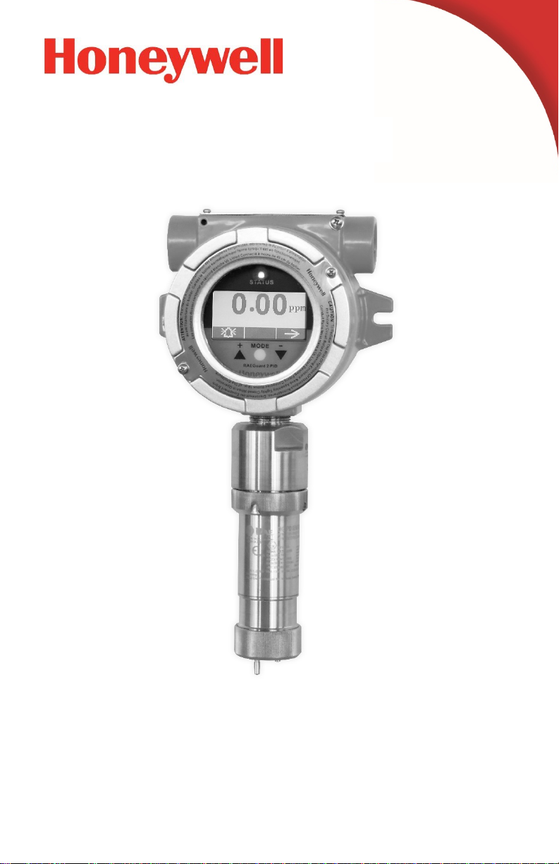
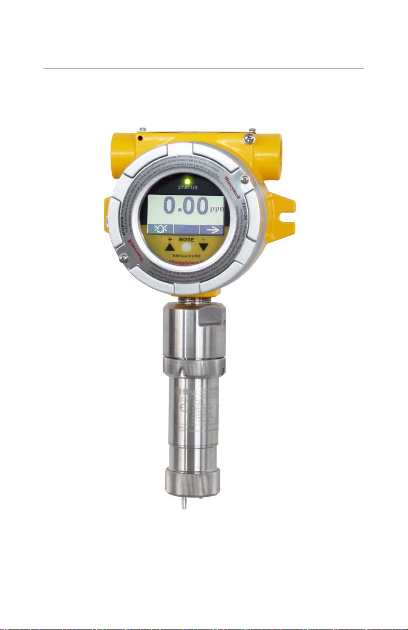
1 General Information
The RAEGuard 2 PID is a fixed photoionization detector (PID) that
measures a broad range of volatile organic compounds (VOCs). It
operates on 10 to 28 VDC and provides an analog (4-20mA) threewire signal output, and RS-485 Modbus digital signal output.
RAEGuard 2 PID uses an intelligent processing platform and digital
sensor technology, supports multiple ranges and resolutions, and can
perform off-line calibration and environmental self-adaptation.
RAEGuard 2 PID has a graphic display and local sound alarm and
light status indicator. A magnetic key interface enables the detecto r to
be calibrated and operational parameters adjusted with the explosionproof enclosure in place. In addition, the PID module can be easily
removed in hazardous locations for calibration or maintenance.
Key features:
• Digital Smart Sensor Technology
• Three wires, supports 4-20mA analog output
• Operates in flow-through mode and can be used in most
environments
• RS-485 digital communication in ModBus protocol
• Explosion-proof stainless-steel enclosure for hazardous
environment applications
• Magnetic-key interface eliminates the need to open the explosion-
proof housing when adjusting parameters.
• Matrix LCD of 128x64 supports graphic display
• LED alarms when High or Low alarm point is reached
• Operation at 10 to 28 VDC
• Three dry contacts (<30V, 2A) normally open (or normally closed),
one for High and Low alarm, another for Fault alarm
Page 8
7
ATEX
II 2 (1) G Ex db [ia Ga] IIC T4 Gb
UL/CSA
Class I, Div. 1, Groups A B C D T4
IECEx
TR CU
Ex db [ia Ga] IIC T4 Gb
1Ex d [ia Ga] IIC T4 Gb X
RAEGuard 2 PID User’s Guid e
Applications:
• Refineries, petrochemical and natural gas plants
• Metallurgical
• Chemical, medication
• Environmental protection
• Electricity, communications
• Fire protection
• Utilities
• Pulp and paper, printing
• Storage
• Sewage disposal
• Food, brewing
• Scientific research, education, homeland security
Hazardous Location Classification:
Page 9

8
Basic Parameters
Principle
PID (photoionization detector)
Sensor
Digital Smart Sensor
Sampling
Internal diaphragm pump
Working Current
DC 10 to 28V, 210mA at 24V
Power
<5W
• 4-20mA
RS-485 (Supports Modbus)
IP Rating
IP-65
Mechanical
Interface
3/4" NPT Male
Installation
2" pipe-holding or wall mounting
User Interface
Three-key magnetic bar adjustment
Calibration
Two or three points
Environmental Parameters
Temperature
-20° C to +55° C (-4° F to 131° F)
Humidity
0 to 95% relative humidity, non-condensing
Pressure
90 to 110kPa
Display
128x64 matrix backlit LCD, supports graphic
display
RAEGuard 2 PID User’s Guid e
2 General Specifications
2.1 RAEGuard 2 PID Specifications
Output
Display
• Three-level programmable alarm relays
(30 VDC, 2A)
•
Page 10
9
Physical Parameters
Dimensions,
L x W x H
257 x 201 x 107 mm
(10.1" x 7.9" x 4.2")
Material
Stainless steel
Weight
3.5 kg (7.7 lbs)
Certification
ATEX
II 2 (1) G Ex db [ia Ga] IIC T4 Gb
UL/CSA
Class I, Div. 1, Groups A B C D T4
IECEx
Ex db [ia Ga] IIC T4 Gb
TR CU
1Ex d [ia Ga] IIC T4 Gb X
Ex Entity
Parameters
Um: 28VDC (input supply)
RAEGuard 2 PID User’s Guid e
RAEGuard 2 PID Specifications (continued)
Sensor Specifications: See DigiPID sensor section on page 59.
2.2 Proper Product Disposal At End Of Life
The Waste Electrical and Electronic Equipment
(WEEE) directive (2012/19/EU) is intended to
promote recycling of electrical and electronic
equipment and their components at end of life. This
symbol (crossed-out wheeled bin) indicates
separate collection of waste electrical and electronic
equipment in the EU countries. This product may
contain one or more Nickel-metal hydride (NiMH),
Lithium-ion, or Alkaline batteries. Batteries must
be recycled or disposed of properly.
At the end of its life, this product must undergo separate
collection and recycling from general or household waste.
Please use the return and collection system available in your
country for the disposal of this product.
Page 11

10
RAEGuard 2 PID User’s Guid e
3 Operation
The calibration of all newly purchased Honeywell Analytics
instruments should be tested by exposing the sensor to a known
concentration calibration gas before the instrument is used or put into
service. Prior to factory shipment, the RAEGuard 2 PID is calibrated
and tested. However, the user should calibrate the instrument before
the first use.
Kit Accessories include: RAEGuard 2 Magnet Key, and User’s
Guide.
Page 12
11
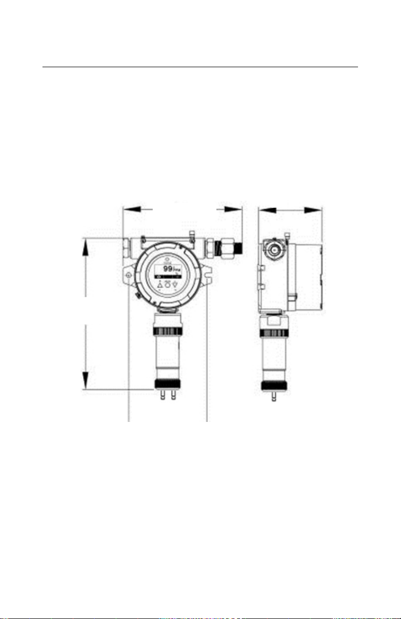
201mm (7.9")
290 mm
(11.4")
133 mm
107mm
RAEGuard 2 PID User’s Guid e
4 Physical Desc ript ion
The RAEGuard 2 PID can be easily installed and integrated with
various control systems. It is designed with flexible pipeholding/wall-mounting options and standard connection terminals.
5 Physical Dimen sio ns
The physical dimensions are as shown:
(4.2")
(5.23")
Page 13
12
WARNING
RAEGuard 2 PID User’s Guid e
6 Installation and Access Instructions
1. To prevent ignition of hazardous atmospheres, area must
be free of flammable vapors and supply circuit must be
disconnected before removing cover.
2. For European application, the installation must comply
with the requirements of EN 60079-14.
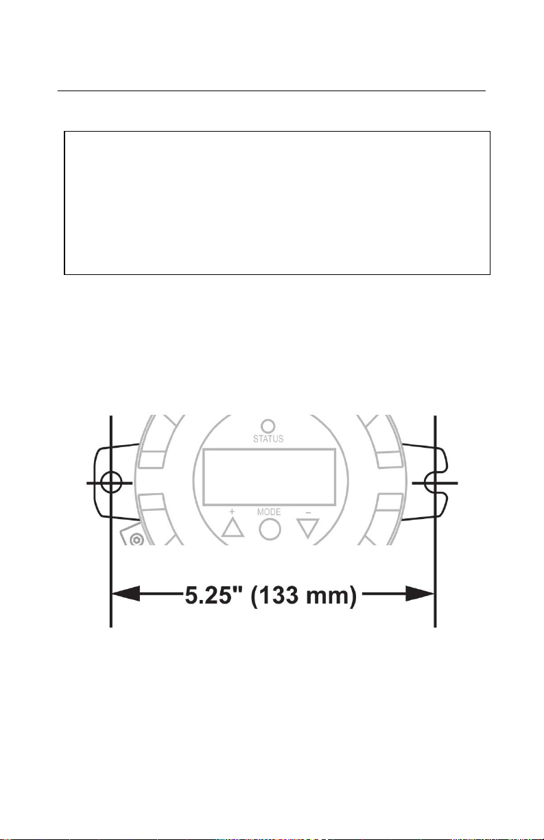
6.1 Mounting
First, decide where the transmitter will be mounted. (Refer to
installation drawing, below.) Drill two holes in mounting surface,
with the center of the holes 5.25" (133mm) apart.
Besides directly mounting the RAEGuard 2 PID to a wall, it can be
mounted on a pipe.
Page 14
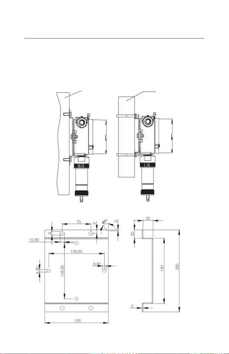
13
Wall
Pole
RAEGuard 2 PID User’s Guid e
Note: When installing the RAEGuard 2 PID, make sure the sensor is
vertically oriented (pointing straight down). Also, make sure the
water-trap filter is connecte d to the gas inlet labeled “IN” (the longer
of the two inlets). Note: Only operate the RAEGuard 2 PID in a noncondensing environment.
Page 15
14
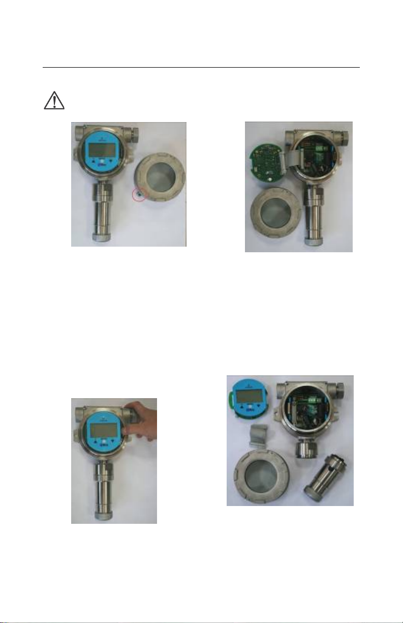
1. Loosen the fastening bolt
3. Tilt the instrument assembly
4.
5.
6.
Disassembled instrument.
2. Pull off the retaining
RAEGuard 2 PID User’s Guid e
6.2 Instrument Disassembly
Prior to service: Make sure power is OFF. Observe all
Hazardous Location Safety procedures.
before unscrewing the
housing lid. Unscr ew the
housing lid from th e housing
body by rotating it counterclockwise. (As shipped, one
of the conduit holes is
covered by the provided hexhead plug. The other c onduit
is for wire connections.)
clip to release the
instrument assembly.
90˚.
Unlock the 24-pin connector
on the ribbon cable.
Lift the entire instrument
assembly out of the housing.
Unscrew the sensor by
turning it counterclockwise.
Page 16
15
Terminal blocks
RAEGuard 2 PID User’s Guid e
To reassemble the instrument:
1 Reconnect the 24-pin connector of the ribbon cable and lock it in
place.
2 Fasten the cable to the board.
3 Mate the board with the clip on the left side and tilt it over.
4 Click the board into place.
5 Screw on the sensor, making sure not to block the gas inlet hole
and connectors.
6 Screw on the housing top.
7 Screw down the fastening bolt.
6.3 Electrical Wiring
The detector connects to peripheral equipment via three terminal
blocks. These blocks accept 12AWG to 24AWG wire (0.2 to 4.0
2
mm
).
Page 17
16
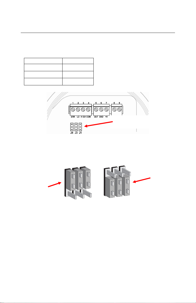
Terminal
description
Failure Alarm Contact
ERR
1
Low Level Alarm Contact
LOW
2
High Level Alarm Contact
HIGH
3
Switch signal Common Contact
COM
4
4-20 mA Output
OUT
5
Power Supply Negative
GND
6
Power Supply Positive
+V
7
RS485A terminal
485A
8
RS485B terminal
485B
9
RAEGuard 2 PID User’s Guid e
6.4 Wiring Procedure
1. Inside the housing bottom, unplug the two green terminal block
plugs from the terminal block on the PC boards.
Note: The terminal block plugs accept 12 AWG to 24 AWG wire.
2. Lace the wires through the RAEGuard 2 PID’s wire hole(s) and
connect wires to the corresponding pin numbers of the terminal
blocks:
Terminal Terminal Definition
Block 1
Block 2
Block 3
No.
Page 18
17
M4 flat washer
M4 Split washer
M4 Screw
Wire
Crimped terminal
Internal earth
RAEGuard 2 PID User’s Guid e
6.5 Earth Grounding Instructions
6.5.1 External Earth Grounding
Fasten the crimped ground wire with hardware as illustrated below.
The wire should have a minimum cross-section area of 4mm
conductor.
(Min. 4 mm2
cross-section)
6.5.2 Internal Earth Grounding
Use the same hardware as shown in the illustration of external earth
grounding. The wire should be no less than the size of the power lines.
Signal grounding can connect to a cable’s shielding layer if shielded
cable is used. If a separate wire is used for g roun ding , its cross section
should be greater than that of the power line.
grounding
2
for its
Page 19
18
Alternate
Internal earth
External earth
RAEGuard 2 PID User’s Guid e
6.5.3 Finished Grounding Wires
Internal and external grounding are shown here, as well as an
alternate external grounding point. Always follow local electrical
guidelines.
grounding
grounding
earth
grounding
point
6.6 Alarm Contact Setup
The alarm contacts can drive external alarms such as a light or buzzer.
By default, the three relays are set for normally open (NO) operation,
meaning that contact is closed when in alarm.
You can separately change each relay from normally open to
normally closed (NC) operation by changing the position of the
jumpers on the internal printed circuit board.
Page 20
19
Jumper
Function
J1
High
J3
Low
J4
Error
Jumper blocks
Normally
Normally
RAEGuard 2 PID User’s Guid e
Three jumper blocks are located below the three green terminal
blocks. They are labeled (from left to right): J4, J3, and J1. Here are
their functions:
Lift off the jumper for each one that you want to change and slide it
back on, either connecting the middle and top points or middle and
bottom points.
Closed
Once the system is operational, test the functionality of all three
relays.
Note: The relays may be disabled based on the sensor that is attached
to the RAEGuard 2 PID. Certain sensors, such as the 1-1000 ppm
DigiPID, disable the correction factor library and relays of the
RAEGuard 2 unit. Users who require these functions should use the
0.1-1000 ppm DigiPID sensor module.
Open
Important!
Page 21
20
Magnet
SIDE VIEW
RAEGuard 2 PID User’s Guid e
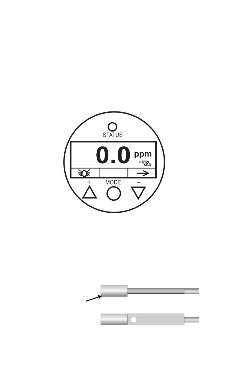
7 Display And User Interface
7.1 User Interface
The RAEGuard 2 PID’s user interface consists of a status LED, an
LCD display, and three keys, [+], [MODE], and [-]. The three keys
are operated by using the Magnet Key.
RAEGuard 2 PID user interface.
7.2 Magnet Key
The RAEGuard 2 PID has no external switches, but instead uses the
magnetic end of the RAEGuard Magnet Key (p/n 033-3032-000) to
activate switches built into the unit.
TOP VIEW
Page 22
21
RAEGuard 2 PID User’s Guid e
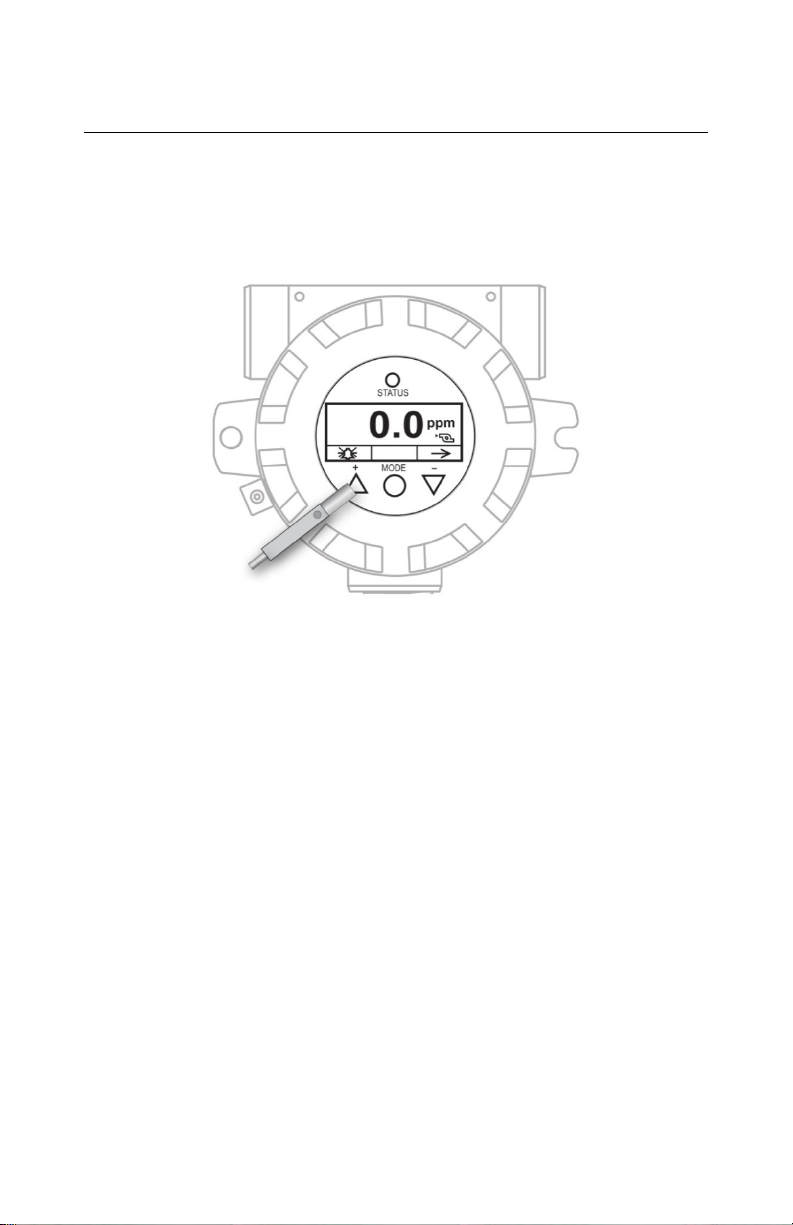
7.3 Using The Magnet Key
Using the magnet end of the Magnet Key, briefly touch the glass
above the MODE circle or the triangles labeled [+] and [-]. Then
remove the key straight out and away from the RAEGuard 2 PID.
RAEGuard Magnet Key touching glass above the [+] triangle.
Important! Never drag the key sideways, or two functions may be
activated.
7.4 System Initialization
When the RAEGuard 2 PID’s system power is turned on, it initializes
and a Honeywell logo appears on the display. As the transmitter is
warming up, each component is checked. The countdown timer
appears on the screen for the warm-up.
7.5 Reading Display
As the transmitter enters the Reading Display, it automatically starts
testing for errors and goes through a cycle of checking each alarm
condition. If there are no errors or alarm conditions, the green “OK”
LED is lit and the gas concentration is displayed.
Page 23
22
External
Alarm
Output
Current
Normal
-
Green
Reading
Reading
Low alarm
Alarm Limit
Red flashing, 2
Hz
High alarm
Alarm Limit
Red flashing, 3
Hz
Red flashing, 3
Hz
Yellow flashing,
1 Hz
Yellow flashing,
1 Hz
Sensor
Drift
Calibration
Fault
Yellow flashing,
1 Hz
Humidity
Sensor Fault
RAEGuard 2 PID User’s Guid e
If there is an error, the “Fault” LED blinks and an error message
blinks. Each alarm condition has a corresponding LED that blinks an
amber color when the readings are outside a specified range or limit.
7.6 Instrument Status Display
After warm-up, the detector enters the Status Display. It automatically
starts testing for errors and goes through a cycle of checking each
alarm condition. If there is no error message or alarm condition, gas
concentration is displayed and LED flashes green.
If there is an error or alarm, a corresponding message shows on the
screen, and the LED indicates different statuses:
Status
LOW
HIGH
Over Range HIGH
Pump Error ERR
Lamp Error ERR
Negative
--
Yellow flashing,
1 Hz
ERR
ERR Green, 1 Hz
LED LCD
Reading Reading
Reading Reading
22mA
2mA
2mA
2mA
2mA
Reading
Page 24
23
Hold
Reading
Sensor
breakdown
Sensor
breakdown
RAEGuard 2 PID User’s Guid e
Auto-zero
Calibration
failure,
sensor not
installed, or
barrier
failure or
barrier
-- --
ERR
ERR
Yellow flashing,
Yellow flashing,
1 Hz
1 Hz
Present
2mA
2mA
Note: Electronic auto-zero calibration takes 1 minute every
half-hour.
8 Navigating Settings
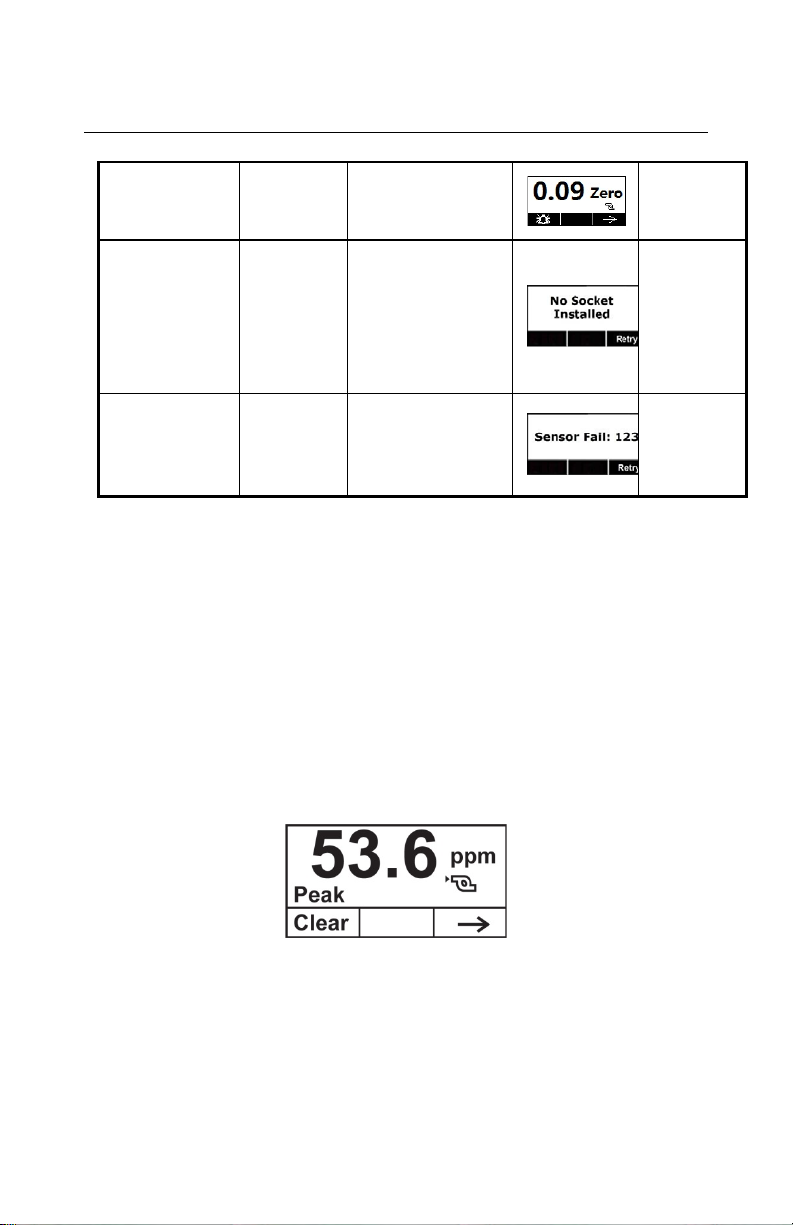
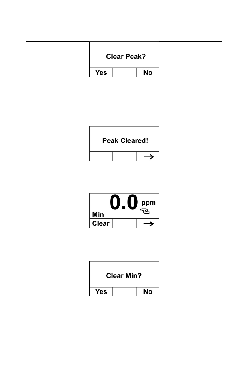
You can view the basic settings, clear the Peak and Minimum readings,
and perform a test of the Analog system without entering P rogramm ing
Mode.
At the main reading screen, hold the magnetic key over [-] for two
seconds. The RAEGuard 2 screen changes to show the current peak
value in memory:
• If you do not want to clear the peak value, press [-].
• To clear the peak value (reset it), press [+].
This screen appears:
Page 25
24
RAEGuard 2 PID User’s Guid e
• If you do not want to clear the peak value, press [-]. The screen
advances to Min. Clear.
• To confirm that you want to clear the peak value (reset it), press
[+]. The value is cleared, and this screen is shown:
Advance to the next screen, Min value, by pressing [-].
• If you do not want to clear the minimum value, press [-].
• To clear the minimum value (reset it), press [+].
• If you do not want to clear the minimum value, press [-]. The
screen advances to Min. Clear.
• To confirm that you want to clear the minimum value (reset it),
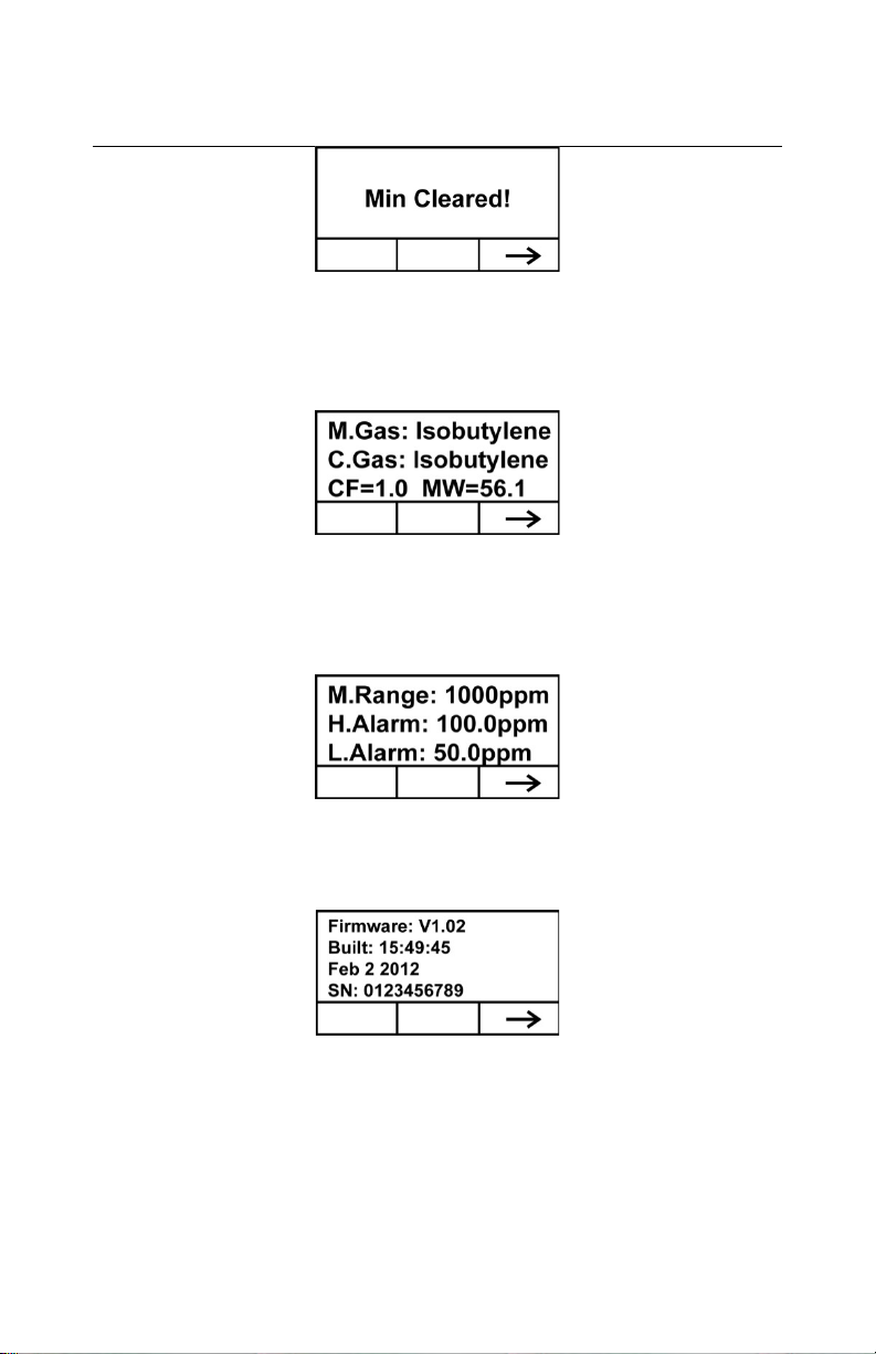
press [+]. The value is cleared, and this screen is shown:
Page 26
25
RAEGuard 2 PID User’s Guid e
Press [-] to advance to the screen showing the measurement gas,
calibration gas, correction factor (CF), and molecular weight (MW) of
the gas:
Press [-] to advance to the screen showing the measurement range
(M.Range) and high alarm (H.Alarm) and low alarm (L.Alarm)
values:
Press [-] to advance to the screen showing the firmware version and
build time and date, and the serial number of the instrument:
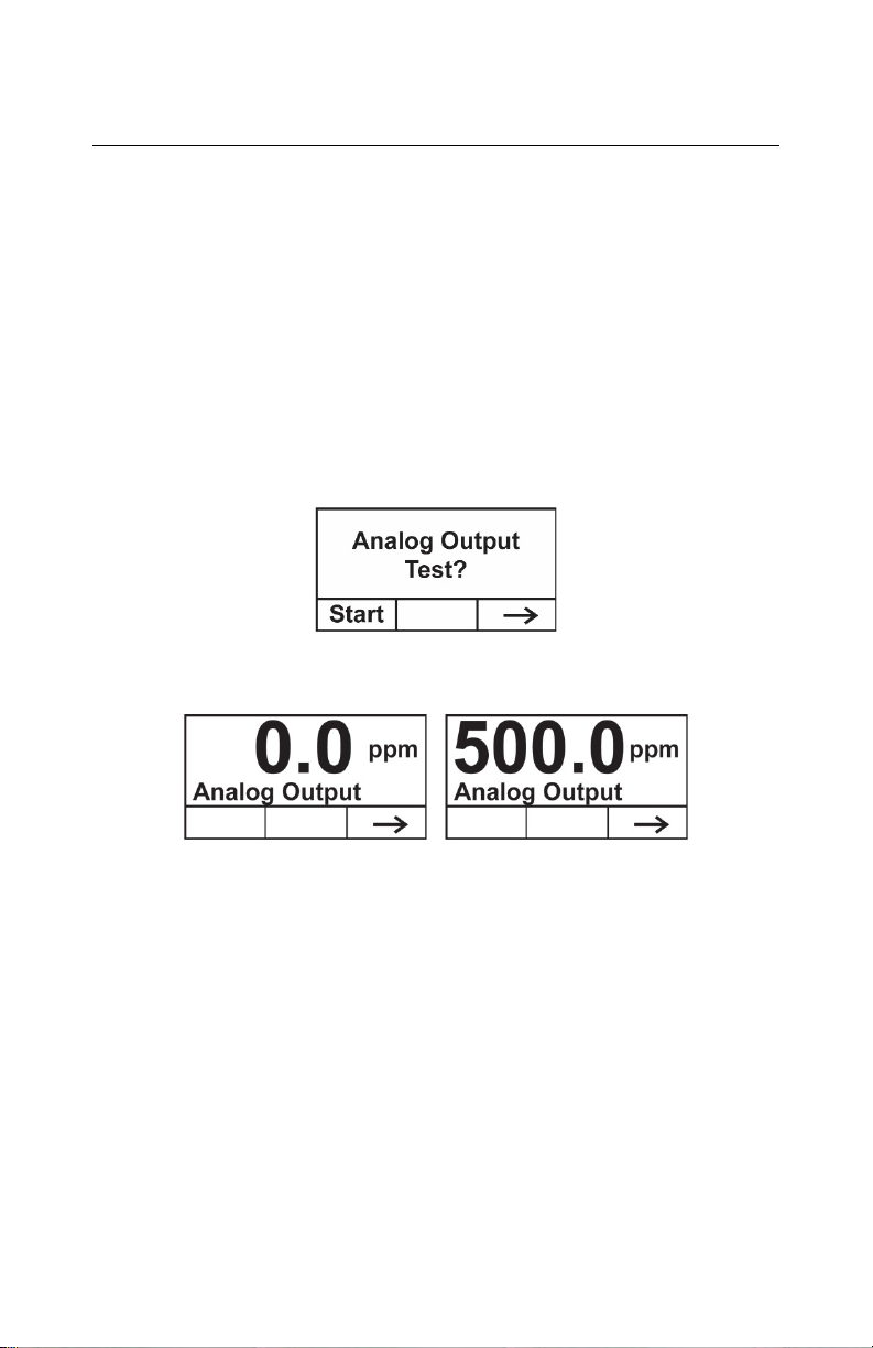
Press [-] to advance to the Analog Output Test screen.
The analog output test is primarily used when commissioning a
system. It ensures that the mA output at the sensor location is the
same as the input received on the system controller. Run the analog
test to make sure that the readings on the detector match the readings
on the controller.
Page 27
26
RAEGuard 2 PID User’s Guid e
The analog test uses a timed step function to output specific mA
values in sequence. The test starts at 4 mA, which typic al ly
corresponds to 0 ppm output. The analog test then progresses in
increments of 2 mA (4, 6, 8, etc., all the way up to 20mA). The
corresponding sensor reading in ppm is shown on the unit’s LCD
display.
For example, if you have a sensor range of 0 to 1000 ppm, the
detector LCD displays in sequence 0, 125, 250, 375…all the way up
to 1000 ppm. These are the ppm equivalent values of 4,6, 8, 10, etc.,
all the way up to 20mA.
Note: You can stop the test and exit at any time by pressing [-].
Page 28
27
Calibration
Measurement*
Alarm Setting
Monitor Setup
Zero/Fresh
Calibration
Meas. Unit*
High Alarm
Temp. Unit
Span Calibration
Meas. Range*
Low Alarm
Language
Set Span Value
Meas. Gas*
Ext. Alarm
Delay*
Pump Duty (%)*
Calibration
Type*
Pump Cycle(s)*
Calibration Gas*
Pump Status*
Set Zero Offset*
Bus Baudrate
Analogout 4mA
Analogou t 20mA
Unit ID
LCD Contrast
LCD Backlight
Change
Password*
RAEGuard 2 PID User’s Guid e
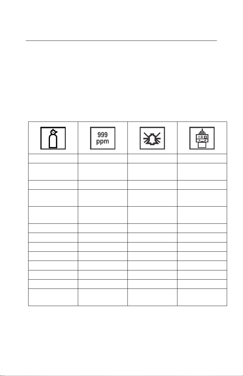
9 Programming Menus
Programming allows anyone with the password to change the
instrument’s settings, calibrate the instrument, etc. Depending on
whether you use the Basic or Advanced Mode, both of which have
different passwords, you can access different menus and submenus.
This table shows the menus (and their icons) and submenus. Items
marked with an asterisk (*) are only available in Advanced Mode.
They are not available in Basic Mode.
Page 29

28
RAEGuard 2 PID User’s Guid e
9.1 Entering Programming Mode
Enter Programming Mode by using the magnetic key to press these
buttons in sequence:
1. Press [+].
2. Press [-].
3. Press [MODE].
The password screen appears, with the cursor on the first digit:
Input the 4-digit password:
• Increase the number from 0 through 9 by pressing [+].
• Step from digit to digit using [-].
• Press [MODE] when you are done.
If you make a mistake, you can cycle through the digits by pressing
[-] and then using [+] to change the number in each position.
Note: The default password for Basic Mode is 1111.
The default password for Advanced Mode is 1250.
Once you enter Programming Mode, the LCD displays the first menu,
Calibration. Each subsequent menu is accessed by pressing [-]
repeatedly until the desired menu is displayed. To enter a submenu of
a menu, press [+].
The Calibration label is shown and its icon is highlighted, but you can
press [-] to step from one programming menu to the next, with the
name of the menu shown at the top of the display and the
corresponding icon highlighted.
Page 30

29
RAEGuard 2 PID User’s Guid e
As you repeatedly press [-], the selection moves from left to right, and
you see these screens in sequence:
9.2 Calibration
Two types of calibration are available: Zero (f resh ai r) and Span.
Note: Complete calibration procedures are detailed on page 43.
Press [+] to select Calibration. Otherwise, press [MODE] to go back,
or press [-] to advance to the next menu.
The Calibration screen is shown:
Select Zero or Span Calibration by pressing [-]. Once your choice is
highlighted, press [+].
Page 31

30
RAEGuard 2 PID User’s Guid e
Zero/Fresh Calibration
Your options are indicated along the bottom of the screen:
• Press [+] to start.
• Press [MODE] to quit and return to the menu.
If you choose to start zero/fresh air calibration, you see this message:
Please apply zero gas…
Connect the zero gas, start its flow, and then press [+]. There is a
countdown as calibration is performed.
Note: After zero/fresh calibration is complete, and with zero gas still
applied, copy the numbers shown in the display and add these to the
current Zero Offset.
Span Calibration
Your options are indicated along the bottom of the screen:
• Press [+] to start.
• Press [MODE] to quit and return to the menu.
If you choose to start span calibration, you see this message:
Please apply gas…
Connect the calibration gas, start its flow, and then press [+]. There is
a countdown as calibration is performed.
Page 32

31
RAEGuard 2 PID User’s Guid e
Calibration Type (Advanced Mode)
You can set the calibration type as follows:
• 2 Points Calibration: Zero and Span Low
• 3 Points Calibration: Zero, Span Low and Span High
Note: The default calibration type is two points.
Calibration Gas (Advanced Mode)
You can set the gas that you want as your calibration gas.
Note: The default calibration gas is isobutylene.
Calibration gases are organized in two lists:
• Last Ten is a list of the last ten gases used by your instrument.
The list is built automatically and is only updated if the gas
selected from the Gas Library is not already in the Last Ten. This
ensures that there is no repetition.
• Gas Library is a library that consists of all the gases found in the
Tech Note_RAE PID_Correction Factors_APN0112 (available
online at www.honeywellanalytics.com or ask your Honeywell
Representive).
Press [-] to step between the two options.
•
Press [MODE] to go back to the menu level above it.
•
Press [+] to select your choice and advance to its submenu.
•
Then follow the steps for the type of selection group you have
chosen:
Last Ten
1. Step through the list’s gases by pressing [-].
2. Register your selection by pressing [+].
3. Save your choice by pressing [MODE].
Page 33

32
Abbreviation
Unit
ppm
parts per million
mg/m3
milligrams per cubic meter
RAEGuard 2 PID User’s Guid e
Gas Library
1. Step through the list’s gases by pressing [-].
2. Register your selection by pressing [+].
3. Save your choice by pressing [MODE].
Whenever you change the calibration gas type, you must set the
Note:
span value.
Set Zero Offset (Advanced Mode)
The Zero Offset menu allows you to cancel baseline noise. T he rang e
is 0.00 to 5.00 ppm. The recommended range for field applications is
0.00 to 1.00.
9.3 Measurement (A dvanced Mode)
Measurement settings allow you to set measurement units, range, gas,
and other parameters.
Meas. Unit (Advanced Mode)
Standard available measurement units include:
1. Press [-] to move the cursor from “ppm” to “mg/m3” or cycle
through them.
2. Press [+] to register your choice.
Page 34

33
RAEGuard 2 PID User’s Guid e
3. Press [MODE] to save the selection.
4. Press [+] to save the Measurement Unit, [MODE] to return to
editing it, and [-] to cancel the change.
The new Measurement Unit is saved, and the RAEGuard 2 PID
exits back to the “Monitor Setup” menu.
Meas. Range (Advanced Mode)
Each sensor head has a maximum range for its sensor (for instance,
100 ppm). However, if you want to increase sensitivity in a lower
range, it is possible to change the measurement range (from the preset
100 ppm to 60 ppm, for example).
1. Press [+] to increase the number from 0 to 9 (it wraps around
to 0 again after 9).
2. Press [-] to step through digits.
3. Press [MODE] to save the new value.
If you have set a value that is within range, then you see this screen:
• Press [+] to save the new value.
• Press [MODE] to go back and edit it again.
• Press [-] to exit without making a change.
If the value is within the sensor’s range when you press [+], the value
is saved and “Saved!” is displayed. If you have set a value that is
outside the sensor’s range, you see this, along with a message that
says, “Invalid Input!”:
Page 35

34
RAEGuard 2 PID User’s Guid e
You have two options:
• Press [-] to exit without making a change.
• Press [+] to go back to change the value.
Meas. Gas (Advanced Mode)
PIDs can be calibrated to a reference gas, yet display the
concentration readings in equivalent units of the target gas.
Isobutylene is typically used as the calibration gas because it is
inexpensive, readily available, has immediate sensitivity, and has very
low toxicity. Th e RAEGuard 2 PID can display concentrations of
over 200 gases using the built-in library of correction factors. PIDs
use a correction factor (CF) that converts the span gas con cen trat ion
(typically, isobutylene) to the measurement gas concentration.
Note: The measurement gas option may be disabled based on the
sensor that is attached to the RAEGuard 2 PID. Certain sensors, such
as the 1-1000 ppm DigiPID, disable the correction factors and relays
of the RAEGuard 2 unit. Users who require these functions should
use the 0.1-1000 ppm DigiPID sensor module.
Measurement gases are organized in two lists:
• Last Ten is a list of the last ten gases used by your instrument.
The list is built automatically and is only updated if the gas
selected from the Gas Library is not already in the Last Ten. This
ensures that there is no repetition.
Gas Library
•
Tech Note_RAE PID_Correction Factors_APN0112 (available
online at www.honeywellanalytics. com or ask your Honeywell
Representive).
Press [-] to step between the two options.
•
Press [MODE] to go back to the menu level above it.
•
Press [+] to select your choice and advance to its submenu.
•
is a library that consists of all the gases found in the
Page 36

35
RAEGuard 2 PID User’s Guid e
Then follow the steps for the type of selection group you have
chosen:
Last Ten
1. Step through the list’s gases by pressing [-].
2. Register your selection by pressing [+].
3. Save your choice by pressing [MODE].
Gas Library
1. Step through the list’s gases by pressing [-].
2. Register your selection by pressing [+].
3. Save your choice by pressing [MODE].
9.4 Alarm Setting
During each measurement period, the gas concentration is compared
with the programmed high and low gas concentration alarm limits. If
the concentration exceeds any of the preset limits, the alarms (and
relays) are activated immediately to warn of the alarm condition.
An alarm signal summary is shown in the Instrument Status Display
table on page 48.
In this menu, you can change the High and Low alarm limits. Press
[Y/+] to enter the Alarm Setting menu.
Note: All settings are shown in ppm (parts per million).
1. Select High or Low Alarm by pressing [-].
2. Press [+] to select edit that alarm’s setting. The display shows
a flashing cursor on the left-most digit of the previously
stored alarm setting.
3. Press [+] to increase each digit’s value.
4. Press [-] to advance to the next digit.
5. Again, use [+] to increase the number.
Page 37

36
RAEGuard 2 PID User’s Guid e
Repeat this process until all numbers are entered.
Press [MODE] when you are done.
Note: If you set an invalid input value, then it says “Invalid input!”
and this set of buttons is shown along the bottom of the display:
Press [MODE] to go back and input a valid value.
•
Press [-] to exit back to the main menu without making a
•
change.
Ext. Alarm Delay (Advanced Mode)
In order to prevent false alarms, you can set a delay time between
when an alarm event occurs and when the RAEGuard 2 sends out the
alarm signal, up to 60 seconds. If the alarm duration is less than the
alarm delay setting, then no relays will be triggered.
1. Press [+] repeatedly to select a desired number. Numbers
increase from 0 to 9. Once 9 is reached, pressing [+] again
“wraps” around back to 0.
2. Press [-] to advance to the next digit.
Repeat this process until all digits of the new value are
entered.
3. Press [MODE] to register the Ext Alarm Delay value.
4. Press [+] to save the value, [MODE] to go back and edit the
value, or [-] to cancel and return to the menu.
Note: If you set an invalid input value, then it says “Invalid input!”
and this set of buttons is shown along the bottom of the display:
Press [MODE] to go back and input a valid value.
•
Press [-] to exit back to the main menu without making a
•
change.
Page 38

37
RAEGuard 2 PID User’s Guid e
9.5 Monitor Setup
This menu has sub-menus for setting the date, time, and other
parameters.
Temp. unit
Set the temperature units to either Fahrenheit or Celsius.
1. Press [-] to place the cursor on the temperature unit you want.
2. Press [+] to make the selection.
3. Press [+] to save your selection, exit the Temp. unit submenu
and return to the Monitor Setup menu.
Note: If you do not want to save the change and want to
make further changes, press [MODE]. Press [-] to exit
without saving the changes.
Language
Choose from English or Chinese.
1. Press [-] to place the cursor on the language you want.
2. Press [+] to make the selection.
3. Press [MODE] to save your selection, exi t the Language
submenu and return to the Monitor Setup menu.
Pump Indicator
When the pump is running, a pump icon is shown on the screen.
When the pump is off, the pump icon is not shown.
Page 39

38
RAEGuard 2 PID User’s Guid e
Pump Duty (%) (Advanced Mode)
The pump’s duty cycle is the ratio of its on time to off time. The duty
cycle ranges from 30% to 70% (always on), and the default period is
10 seconds. Therefore, a duty cycle of 60% means that the pump is on
for 6 seconds and off for four seconds. The patented duty cycling is
employed by the instrument to clean the PID. A lower duty cycle has
a greater effect on keeping the PID clean than a higher duty cycle.
Important! Pump duty cycling is interrupted when the instrument
senses a gas. The pump’s duty cycle is disabled when the
measurement is greater than the low-alarm threshold and is re-enabled
when the reading falls below the low-alarm threshold. The alarm
threshold can be set, following the instructions on page 35.
1. Press [+] repeatedly to select a desired number. Numbers
increase from 0 to 9. Once 9 is reached, pressing [+] again
“wraps” around back to 0.
2. Press [-] to advance to the next digit.
Repeat this process until all digits of the new value are
entered.
3. Press [MODE] to register the Pump Duty value.
4. Press [+] to save the value, [MODE] to go back and edit the
value, or [-] to cancel and return to the menu.
Note: If you set an invalid input value, then it says “Invalid input!”
and this set of buttons is shown along the bottom of the display:
Press [MODE] to go back and input a valid value.
•
Press [-] to exit back to the main menu without making a
•
change.
Page 40

39
RAEGuard 2 PID User’s Guid e
Pump Cycle(s) (Advanced Mode)
This sets the length of time for one cycle of the pump running.
Range = 10 to 300 seconds. Default value = 10.
1. Press [+] repeatedly to select a desired number. Numbers
increase from 0 to 9. Once 9 is reached, pressing [+] again
“wraps” around back to 0.
2. Press [-] to advance to the next digit.
Repeat this process until all digits of the new value are
entered.
3. Press [MODE] to register the Pump Cycle(s) value.
4. Press [+] to save the value, [MODE] to go back and edit the
value, or [-] to cancel and return to the menu.
Note: If you set an invalid input value, then it says “Invalid input!”
and this set of buttons is shown along the bottom of the display:
Press [MODE] to go back and input a valid value.
•
Press [-] to exit back to the main menu without making a
•
change.
Pump Status (Advanced Mode)
This tells you whether the pump should be on or off, and allows you
to set whether the pump is on or off.
Press [-] to select On or Off (the black dot in the circle
•
indicates the selection).
Press [+] to make the change to your selection.
•
Press [MODE] if you want to exit without making a change.
•
Page 41

40
RAEGuard 2 PID User’s Guid e
Bus Baudrate
Choose from three different baud rates for Modbus data transmission:
4800, 9600, or 19200.
1. Press [-] to place the cursor on the baud rate you want.
2. Press [+] to make the selection.
3. Press [MODE] to save your selection.
4. Press [+] to store the selection and exit the submenu and
return to the Monitor Setup menu.
Note: If you do not want to save the change and want to
make further changes, press [MODE]. Press [-] to exit
without saving the changes.
Analogout 4mA
This feature sets the analog output to 4mA for system setup and
troubleshooting. (The allowed range is 100 to 199.)
1. Press [+] repeatedly to select a desired number. Numbers
increase from 0 to 9. Once 9 is reached, pressing [+] again
“wraps” around back to 0.
2. Press [-] to advance to the next digit.
Repeat this process until all three digits of the new value are
entered.
3. Press [MODE] to save the 4mA analog output value.
Analogout 20mA
This feature sets the analog output to 20mA for system setup and
troubleshooting. (The allowed range is 3000 to 3999.)
1. Press [+] repeatedly to select a desired number. Numbers
increase from 0 to 9. Once 9 is reached, pressing [+] again
“wraps” around back to 0.
Page 42

41
RAEGuard 2 PID User’s Guid e
2. Press [-] to advance to the next dig it.
Repeat this process until all four digits of the new value are
entered.
3. Press [MODE] to save the 20mA analog output value.
Unit ID
When using Modbus communication, you can give each RAEGuard 2
PID on a network a unique Unit ID that helps identify it. (The Unit ID
range is 01 to 99.)
1. Press [+] repeatedly to select a desired number. Numbers
increase from 0 to 9. Once 9 is reached, pressing [+] again
“wraps” around back to 0.
2. Press [-] to advance to the next digit.
Repeat this process until both digits of the new value are
entered.
3. Press [MODE] to save the 20mA analog output value.
LCD Contrast
The display’s contrast can be increased or decreased from its default setting. You may never need to change the default setting, but sometimes you can optimize the display to suit extreme temperature and ambient brightness/darkness conditions.
1. Press [+] to step through the contrast levels. The range is 1 to
99. Once 99 is reached, pressing [+] again "wraps" around
back to 10.
2. When you have com plet ed y our select ion, pre ss [MODE].
3. Press [+] to save your selection, and exit LCD Contrast.
Note: If you want to make further changes, press [MODE] to
return to the adjustment screen. Press [-] to exit without
saving the changes.
Page 43

42
RAEGuard 2 PID User’s Guid e
LCD Backlight
The backlight glows whenever you press a button with the magnetic
key. In addition, you can set the backlight to be either always on or
only on when an event (alarm) occurs.
1. Press [-] to place the cursor on the setting you want.
2. Press [+] to make the selection.
3. Press [MODE] to save your selection, exit the LCD Ba c k light
submenu and return to the Monitor Setup menu.
Change Password (Advanced Mode)
You can change the four-digit passwo rd for access ing Basic Mode.
The default basic password is: 1111
The advanced password is: 1250
Note: You cannot change the password for accessing Advanced
Mode.
1. Press [+] to step through all 10 numerals (0 to 9).
2. Press [-] to advance to the next digit. The next digit to the
right flashes.
Repeat this process until all four digits of the new password
are entered.
3. Press [MODE] to register the selection.
4. Press [+] to save the new password, [MODE] to return to
editing the password, and [-] to cancel the change.
The new password is saved, and the RAEGuard 2 PID exits back
to the “Monitor Setup” menu.
Page 44

43
WARNING
RAEGuard 2 PID User’s Guid e
10 Calibration
The calibra tio n of all ne wly purc hase d Honeywell Analytics
instrume nts sho ul d be tes ted by exp osi ng t he s ens or(s ) to a
known conc en tra tion cal ibr ati on gas be fore the in str ume nt is
used or put into service. For maxi mum safety, the accuracy of
the RAEGuard 2 PID shou ld be che cked by exposi ng th e sens or
to a known concentration calibration gas.
The RAEGuard 2 PID is calibrated using a two-point calibration process.
First, use a “zero gas.” Then use a “span gas” containing a known
concentration of a standard reference gas, to set the second point of
reference.
Zero calibration must be performed before span calibration.
Note:
RAEGuard 2 PID connected to gas bottle.
To perform a calibration, you need a cylinder of zero gas and a
cylinder of span gas.
Page 45

44
RAEGuard 2 PID User’s Guid e
10.1 Zero Calibration
1. Connect the zero gas cylinder to the gas inlet (“IN”) port on
the RAEGuard 2 PID.
2. In measurement mode, use the magnet key to press [+],
[-], and then [MODE] in sequence.
3. Input your password, followed by [-].
The instrument enters the calibration menu.
4. Press [+] to enter the Calibration menu.
5. Press [-] until “Zero/Fresh calibration” is highlighted.
Press [+], and this screen appears:
6. Start the gas flow.
Page 46

45
RAEGuard 2 PID User’s Guid e
7. Press [+]. A countdown screen is shown as the calibration is
performed:
Note: You may abort the calibration during the countdown by
pressing [-]. If you stop the calibration, the process stops and
this screen is displayed befo re the menu screen is sh own :
8. Once the calibration is complete, this screen is shown:
9. If the calibration is not successful, and you see the “Zero
Calibration Failed” message, check that the inlet is not
blocked and that there are no other problems before retrying.
Note: After zero/fresh calibration is complete, and with zero gas still
applied, copy the numbers shown in the display and add these to the
current Zero Offset.
Page 47

46
RAEGuard 2 PID User’s Guid e
10.2 Span Calibration
1. Connect the calibration gas cylinder to the gas inlet (“IN”)
port on the RAEGuard 2 PID.
Note: Make sure the labeled concentration of calibration gas
matches the value that is set in the RAEGuard 2 PID.
2. If the RAEGuard 2 PID is not already in Programming Mode,
use the magnet key to press [+], [-], and then [MODE] in
sequence.
3. Input your password, followed by [-].
The instrument enters the calibration menu.
4. Press [+] to enter the Calibration menu.
5. Press [-] until “Span calibration” is highlighted.
Page 48

47
RAEGuard 2 PID User’s Guid e
6. Press [+], and this screen appears:
7. Start the gas flow.
8. Press [+]. A countdown screen is shown as the calibration is
performed:
Note: You may abort the calibration during the countdown by
pressing [-]. If you stop the calibration, the process stops and
this screen is displayed before the menu screen is shown:
9. Once the calibration is complete, this screen is shown:
10. If the calibration is not successful, and you see the “Span
Low Failed!” message, check that the inl et is no t bloc ked, the
sensor or lamp are not fouled or damaged, and there are no
other problems before retrying.
Page 49

48
Status
LCD
LED
Indication
Relay Status
Analog
Output
Normal
Green
Failure: Disable
High alarm: Disable
According
Value
Low Alar m
Red
per second)
Failure: Disable
High alarm: Disable
According
Value
High Alarm
Red
per second)
Failure: Disable
High alarm: Enable
According
Value
Over Range
Red
per second)
Failure: Disable
High alarm: Enable
22mA
Pump Error
Yellow
per second)
Failure: Enable
High alarm: Disable
2mA
Lamp Error
Yellow
per second)
Failure: Enable
High alarm: Disable
2mA
Sensor
Drift
Yellow
per second)
Failure: Enable
High alarm: Disable
2mA
Calibration
Yellow
per second)
Failure: Enable
High alarm: Disable
2mA
Humidity
Green
Failure: Disable
High alarm: Disable
According
Value
RAEGuard 2 PID User’s Guid e
11 Alarm Signal Summary
The following are reading-related alarms.
Negative
Failure Error
(2 flashes
(3 flashes
(3 flashes
(1 flash
(1 flash
(1 flash
(1 flash
Low alarm: Disable
Low alarm: Enable
Low alarm: Enable
Low alarm: Disable
Low alarm: Disable
Low alarm: Disable
Low alarm: Disable
Low alarm: Disable
to Reading
to Reading
to Reading
Sensor Error
Low alarm: Disable
to Reading
Page 50

49
Sensor
breakdown
Yellow
Failure: Disable
2mA
Sensor failure
breakdown
Yellow
per second)
Failure: Disable
High alarm: Disable
2mA
RAEGuard 2 PID User’s Guid e
failure,
sensor not
installed, or
barrier
or barrier
(1 flash
per second)
(1 flash
Low alarm: Disable
High alarm: Disable
Low alarm: Disable
Page 51

50
RAEGuard 2 PID User’s Guid e
12 Maintenance
As a guide, it is recommended to regularly “bump test” a RAEGuard
2 PID unit with a known percentage gas. Also, periodically check the
sensor inlet and outlet to make sure they are clean and unobstructed.
13 DigiPID Sensor Module Replacement
When changing the DigiPID’s Sensor Module, you can leave the
main power connected to the RAEGuard 2 PID. However, you must
enter the “Change Sensor” mode, following this procedure:
1. Hold the key over the “+” symbol for 3 seconds.
This screen appears, indicating that power to the DigiPID has
been removed:
WARNING!
The Change Sensor mode must be entered before changing the sensor.
This disconnects power to it. If power is not disconnected, the barrier
can be severely damaged.
Page 52

51
RAEGuard 2 PID User’s Guid e
2. Replace the DigiPID Sensor Module.
3. When the new DigiPID Sensor Module is in place, tap the
key on the “-“ (“Go”).
This restarts the RAEGuard 2 PID.
Page 53

52
Message
Reason and Solution
Reason: Instrument over range.
Check sensor.
Reason: Pump failure.
Check pump.
Reason: Lamp failure.
Solution: Check Sensor.
Reason: Sensor drift.
Adapter.
Reason: Calibration fails.
Honeywell Representive.
Reason: Humidity sensor fa ilu re .
Service or your Honeywell Representive.
Reason: Sensor not installed or sensor failure, or
Service or your Honeywell Representive.
RAEGuard 2 PID User’s Guid e
14 Troubleshooting
Note: Before attempting to diagnose measurement problems, perform
zero and span calibrations.
Solution: Confirm the level of gas concentration.
Solution: Make sure that the air path is not blocked.
Solution: Perform zero and span calibration.
Clean sensor and lamp.
Check metal filters inside Mounting
Solution: Check calibration operation.
Change sensor or contact Honeywell
Solution: Check the humidity in the area.
Make sure that the air path is not blocked.
Contact Honeywell Analytics Technical
Solution: Check sensor and barrier.
Contact Honeywell Analytics Technical
Analytics Technical Service or your
barrier breakdown.
Change sensor or barrier.
Page 54

53
Reason: Sensor failure or barrier breakdown, and
Service or your Honeywell Representive.
RAEGuard 2 PID User’s Guid e
number of minutes since this happened.
Solution: Check sensor and barrier.
Contact Honeywell Analytics Technical
*Note: Using the 0-1000, 1 ppm resolution DigiPID Module with the
RAEGuard 2 will disable the correction factor and relay options on
the RAEGuard 2. Users who require these functions should use the
0.1-1000 ppm DigiPID sensor module.
Change sensor or barrier.
Page 55

54
RAEGuard 2 PID User’s Guid e
SECTION 2: DigiPID User’s Guide
Page 56

55
RAEGuard 2 PID User’s Guid e
SAFETY INSTRUCTIONS
15 Read Before Operating
This manual must be carefully read by all individuals who have or
will have the responsibility of using, maintaining, or servicing this
product. The product will perform as designed only if it is used,
maintained, and serviced in accordance with the manufacturer’s
instructions. The user should understand how to set the correct
parameters and interpret the obtained results.
CAUTION!
Sensor interface connector pins cannot be interchanged for multiple
applications. Apply the sensor in accordance with connector
definitions described in the datasheet and in accordance with the
general fitting rules for the applied intrinsi ca lly safe entity
parameters. Use only Honeywell Analytics lamps and the sensor
detector type specified for your module. Maintain by using only
Honeywell Analytics accessories, including a Teflon filter or UV
shield. Use of non-Honeywell Analytics components will void the
warranty and can compromise the safe performance of this product.
Page 57

56
Intrinseque/Exia
RAEGuard 2 PID User’s Guid e
15.1 DigiP ID Ma rking
The DigiPID is certified according to the IECEx scheme, ATEX and
CSA for US and Canada as protected by intrinsic safety.
The product is marked with the following information:
RAE SYSTEMS
3775 N. 1
CA 95134, USA
DIGI PID
Type DS100/DS101/DS102
Serial No/barcode: XXX-XXXX-000
st
. St., San Jose
IECEx KEM
10.0005
Ex ia IIC T4
Ga
Ex ia I Ma
2460
IM1/II 1G
Ex ia IIC T4 Ga
Ex ia I Ma
KEMA10ATEX0059
Class I, Gr. A,B,C,D T4
Only as to intrinsic safety
for use in hazardous loc.
Intrinsically safe/ Securite
Pi: 1.225W; Vi: 6.13V; Ci: 20.2µF; Ii: 1.5A; Li: 1µH.
-40º C < Tamb < +55º C
Warning: Read User’s Manual for Intrinsic Safety Precautions
Page 58

57
RAEGuard 2 PID User’s Guid e
15.2 Operation Area and Conditions
15.2.1 Hazardous Areas classified by Zones
DIGI PID is intended to be used in hazardous areas or mines
susceptible to firedamp classified zone 0, zone 1 or zone 2, within the
temperature range of -20º C to +55º C, where gases of explosion
groups IIA, IIB or IIC and T4 may be present.
15.2.2 Hazardous Areas classified by Divisions
DIGI PID is intended to be used in hazardous areas classified for
Class I Div. 1 or 2, within the temperature range of -20º C to +55º C,
where gases of explosion groups A, B, C or D and temperature class
T4 may be present.
15.3 Instruction For Safe Use
Strictly follow the instructions for safe use. Application of the
DigiPID requires full understanding and strict observation of the
instructions.
The DigiPID can be connected to Ex-certified equipment for use in
hazardous areas, when it is secured that the connec tio n is com ply ing
with the intrinsically safe input entity parameters for the two units,
and the intended function area corresponds to the certified area.
The DigiPID sensor can be connected and disconnected inside the
hazardous area.
Page 59

58
First digit
Year
J
2008
K
2009
M
2010
N
2011
P
2012
Q
2013
R
2014
S
2015
T
2016
U
2017
V
2018
W
2019
RAEGuard 2 PID User’s Guid e
15.4 Use In Hazardous Areas
Equipment which is intended for use in explosive atmospheres and
which has been assessed and certified according to international
regulations may be used only under specified conditions. The
components may not be modified in any way.
The appropriate regulations for service and repair must be properly
observed during such activities.
15.5 Year of manufacture
To identify the year of manufacture, refer to the serial number of the
instrument.
The second to last digit in the serial number indicates the year of
manufacture. For example, “H” indicates the manufacturing year is
2008.
Page 60

59
Power Supply
5V ±0.25V DC
Current
110 mA max
Power Consumption
< 0.6W
Measuring Range
0.01 to 100 ppm, 0.1 to 1000 ppm, and
1 to 1000 ppm*
Resolution
10 ppb, 100 ppb, 1 ppm (depends on
model)
Response Time
Pumped (T90): 5 s (from the time the gas
tubing is used)
Calibration
Three-point off-line and field calibration
Accuracy
±2% for calibration point
Zero Drift
±10% FSS/Month
Span Drift
±10% FSS/Month
Analog Output
0.5 - 2.5V (ro=1.0k)
Digital Interface
Serial Interface (UART)
Receive (Rx): 3.3V TTL
Sensor Lifetime
2 years
Operating
Temperature
-20º C to +55º C (-4º F to +131º F)
Humidity
0 to 95% RH non-condensing
EMI/RFI
Highly resistant to EMI/RFI
2004/108/EC
Package
Rugged case for 1.2m drop test
protection
Size (DxL)
49mm x 150.8mm (1.92″ x 5.94″)
Weight
< 550g (19.4 oz)
Ex entity parameters
Pi: 1.225W; Vi: 6.13V; Ci: 20.2µF; Ii: 1.5A;
Li: 1µH
RAEGuard 2 PID User’s Guid e
15.6 Specifications
contacts the sensor, longer if sample
Transmit (Tx): 3.3V TTL
Compliant with EMC Directive
Spray watertight for IP65 rating
Dust membrane for sensor front
*Note: Using the 0-1000, 1 ppm resolution DigiPID Module with the
RAEGuard 2 will disable the correction factor and relay options on
the RAEGuard 2. Users who require these functions should use the
0.1-1000 ppm DigiPID sensor module.
Page 61

60
Pin
1 2 3 4 5 6 7
8
Definition
Power
CS
Analog
RXD
Open
GND
Control
TXD
RAEGuard 2 PID User’s Guid e
16 General Information
The DigiPID Sensor is a self-contained intelligent sensor module with
built-in photoionization detector (PID) sensor processor, lamp driver,
and analog and digital interface circuits. It is designed to detect
volatile organic compounds (VOC) and has a standard external
interface. This sensor module can be easily integrated into a wired or
wireless communication system for remote, wide-area, and pervasive
monitoring applications. The sensor module can be powered by a 5V
±0.25V DC power supply. It is housed in a weatherproof enclosure
with a standard 8-pin interface connector. The chart below details the
functions of the eight pins:
Number
In
Signal
Out
Drain
Signal
(optional)
Notes:
Power in: Power supply input connector for the sensor module. The
input voltage range is DC 5V ±0.25V at 200mA.
CS: Communication Select. Select (falling edge) to start
communication, deselect (rising edge) to stop communication.
Analog Signal Out: Analog signal output with 1kΩ output resistance
for the sensor module. The output signal range is between 0.5V and
2.5V.
RXD & TXD: Serial interface poles (receive and transmit) for UART
mode with 3.3V TTL level.
Open drain: Switching signal output pole. It can deliver low or high
level to external equipment according to customer requirements.
GND: Power and signal ground.
Page 62

61
RAEGuard 2 PID User’s Guid e
Control signal: This optional pole only delivers a high (3.3V) or low
(0V) signal lev el.
Caution: 6.2V is the maximum input voltage for all of the sensor
module’s input poles.
17 Ground ing (Earth Connection)
DigiPID includes a grounding connection via pin 6 of the 8-pin
connector. If the complete installation must be grounded, ensure that
the thread on which DigiPID is mounted is correctly grounded.
Check local ordinances regarding further requirements.
Page 63

62
RAEGuard 2 PID User’s Guid e
18 Phy sical Description
The DigiPID is a pumped sensor. The pump is in this version
intended to pump the sample gas in though one of the DigiPID gas
tubes and return it through the other.
Page 64

63
8-pin
Sample outlet
Pump connections
Sensor module
PID Lamp
Sensor detector
Teflon O-ring
Sensor cover with
Optional
Fastening nut
Optional mounting
Sample inlet
RAEGuard 2 PID User’s Guid e
19 Sensor Parts A nd Dimensions
DigiPID sensor shown with optional mounting adaptor
adapter
interface
connector
mounting
adapter
filter installed
Page 65

64
RAEGuard 2 PID User’s Guid e
20 Operating the Sensor Module
20.1 Preparing The Sensor For U se
Make sure the 8-pole input of the external intrinsically safe
equipment matches the interface connector pinout configuration of
the DigiPID. Make sure the input power supply range is between
4.75V and 5.25V DC, and the input current is about 200mA when the
sensor module is operated. The following mechanical drawing
includes the sensor module interface connector’s pinout. The Ex
entity parameter of the equipment connected to the DigiPID must fit
the entity parameters of DigiPID according to intrinsically safe fitting
rules.
8-pin connector pinout configuration:
1: Power in
2: CS (Communication Select). Select (falling edge) to start
communication, deselect (rising edge) to stop communication.
3: Analog Signal Output
4: RXD
5: Open Drain
6: GND
7: Control Signal (Optional)
8: TXD
Note: Some external equipment requires no connection to pins 5 and 7.
Page 66

65
RAEGuard 2 PID User’s Guid e
21 Using The Sensor Module
21.1 Gas Flow Routing Connection
The DigiPID has an “IN” and “OUT” port for sampling gas. Make
sure that the in and out sample tubes are properly oriented.
After making all gas connections and ensuring connection to the 8-pin
connector, turn on the power supply and warm up the sensor module.
Note: A two-hour warm-up time is recommended before making
critical measurements.
Firmly affix the sensor module to external equipment and make sure
the 8-pole interface connector makes a reliable, tight connection with
other equipment.
When you begin measurement, the sensor provides data to external
equipment, showing the current concentration of the specified gas.
Data is output digitally via the UART port or as an analog signal
(0.5V to 2.5V) from pin 3 of the interface connector. The sensor
module can be calibrated for different operations and gases.
If the DigiPID sensor is connected to Honeywell Analytics
equipment, you can affix the sensor module directly to the equipment
and then turn on the instrument’s power supply. The sensor module
runs normally. If the other external equipment is not a Honeywell
Analytics product, additional firmware and software support is
necessary. Honeywell Analytics can provide essential information
such as the handshaking protocol, port setting, flow rating, etc.
Page 67

66
RAEGuard 2 PID User’s Guid e
21.2 Sensor Module Calibration
The sensor module is calibrated before it leaves the factory. However,
you can also calibrate the sensor module. Allow it to warm up for two
hours before calibrating it. Calibration should be performed using
external equipment, using a two-point calibration for the 100 and
1000 ppm VOC sensor.
100 ppm and 1000 ppm range sensor module calibration. First
perform a zero gas calibration by applying fresh air to the sensor
module. If the module is configured for use with a pump, the fresh
air’s flow rate must be greater than the pump’s draw rate. A
calibration time of 1 minute is recommended. The other calibration
point requires exposure of the sensor to span gas. The span gas
concentration should be 10 ppm and 100 ppm (for 100 ppm range) or
100 ppm and 1000 ppm (for 1000 ppm range) isobutylene, and
calibration time is also 1 minute.
IMPORTANT!
When changing the DigiPID’s Sensor Module, you can leave the
main power connected to the RAEGuard 2 PID. However, you must
enter the “Change Sensor” mode, following this procedure:
1. Hold the key over the “+” symbol for 3 seconds.
This screen appears, indicating that power to the DigiPID has
been removed:
Page 68

67
RAEGuard 2 PID User’s Guid e
2. Replace the DigiPID Sensor Module.
3. When the new DigiPID Sensor Module is in place, tap
the key on the “-” (“Go”).
This restarts the RAEGuard 2 PID.
Note: Replacing the DigiPID Sensor Module and then restarting
the instrument resets all settings, including alarm levels, to their
original factory default values.
Page 69

68
Loosening the
RAEGuard 2 PID User’s Guid e
21.3 Maintenance A nd Calibration
The sensor module should be calibrated if it does not pass a bump
test, but no less than every 6 months, depending on use and exposure
to gas and contamination.
21.4 Replacing the Lamp And Filter
The sensor module is shipped with the lamp, sensor, and stainlessfilter installed. Periodically check the filter for dirt and contaminatio n,
which can impact the reading and response time.
Note: Always turn off power to the DigiPID before checking and
servicing any parts. After inspection and/or replacement of parts,
recalibrate th e instrument.
The lamp and sensor are not interchangeable with parts from other
manufacturers; use only Honeywell Analytics replacements. Use of
non-Honeywell Analytics components will void the warranty and
can compromise the safe performance of this product.
fastening nut
allows the DigiPID
to be easily
detached from a
base.
Page 70

69
Housing
Teflon O-ring
PID Lamp
Sensor
Attachment
IMPORTANT!
Filter
IMPORTANT!
Inlet/Outlet
RAEGuard 2 PID User’s Guid e
ring
Align hole in filter
with hole in top of
PID sensor to
ensure
unobstructed
sample flow
Module
Only handle lamp
by holding sides of
end. Do not touch
flat surface.
Page 71

70
RAEGuard 2 PID User’s Guid e
22 Replacing Th e Sensor’s Te flon UV Shield
On the underside of the sensor module is a Teflon UV Shield that
should be replaced every 90 days, in order to ensure sensor accuracy.
1. Dismantle the DigiPID as shown on page 68, and remove the
Sensor Module. Note: Be careful to not touch the PID lamp’s
surface.
2. Remove the Sensor Module, and replace it with a new one (a
spare Sensor Module is included with the unit).
3. Take the old Sensor Module to your shop/service center to
perform the rest of the activities, which will refresh the Sensor
Module and make it ready as a replacement spare.
Note: Teflon UV Shields are available from Honeywell Analytics in
packages of 10.
Page 72

71
Sensor
Discard the used
RAEGuard 2 PID User’s Guid e
4. Unscrew and remove all four of the gold-plated contact “legs”
from the Sensor Module.
5. Use a small flat-bladed screwdriver or similar tool to get between
the Sensor Module and the Teflon UV Shield at the point nearest
the shield’s large “notch,” and gently pry it up.
6. Work the blade or tool around the bottom of the Sensor Module,
lifting the Teflon UV Shield as you go around.
7. Once the Teflon UV Shield has been separated far enough from
the Sensor Module to remove it, use your fingers to pull it over
the four contact “legs” and discard it.
Teflon Sheld
Page 73

72
RAEGuard 2 PID User’s Guid e
8. Slide a new Teflon UV Shield over the contact “legs,” and gently
press it down until it is snug against the surface of the Sensor
Module.
9. Use your fingers to screw on the four contact “legs.”
10. Use a soft, clean cloth to wipe any finger oils from the surface of
the contact “legs,” and set the Sensor Module aside.
11. Inspect the surface of the PID lamp. Clean it with isopropanol on
a swab, as outlined in the next section.
12. After the surface of the PID lamp dries, reassemble the unit.
Page 74

73
RAEGuard 2 PID User’s Guid e
23 Sensor & Lamp Cleaning/Replacement
Clean the PID sensor module, the lamp and housing only if:
1. The reading is inaccurate even after calibration.
2. The reading is very sensitive to air moisture.
3. A liquid has been sucked into the unit and damaged the unit.
Use of the external filter helps to prevent contamination of the sensor.
To access the sensor components and lamp, gently unscrew the sensor
cover. Then hold the PID sensor and pull it straight out. A slight,
gentle rocking motion helps release the sensor.
23.1 Cleaning The PID Sensor
Place the entire PID Sensor Module into isopropanol. It is highly
recommended that an ultrasound bath to be used to clean the sensor
for at least 15 minutes. Then dry the sensor thoroughly. Never touch
the electrodes of the sensor by hand.
Also use an isopropanol-soaked cotton swab to wipe off the lamp
housing where it contacts the sensor when the sensor is installed.
Turn over the sensor so that the pins point up and the sensor cavity is
visible. Examine the sensor electrodes for any corrosion, damage, or
bending out of alignment. The metal sensor electrode “fingers”
should be flat and straight. If necessary, carefully bend the sensor
fingers to ensure that they do not touch the Teflon portions and that
they are parallel to each other. Make sure that the nuts on the sensor
pins are snug but not overtight. If the sensor is corroded or otherwise
damaged, it should be replaced.
Page 75

74
RAEGuard 2 PID User’s Guid e
23.2 Cleaning The Lamp Hou sing Or Changing The Lamp
If the lamp does not turn on, the instrument will display an error
message to indicate replacement of the lamp may be required.
1. If the lamp is operational, clean the lamp window surface and the
lamp housing by wiping it with isopropanol using a cotton swab
using moderate pressure. After cleaning, hold the lamp up to the
light at an angle to detect any remaining film. Repeat the process
until the lamp window is clean. Never use water solutions to
clean the lamp. Dry the lamp and the lamp housing thoroughly
after cleaning.
CAUTION: Never touch the window surface with the fingers
or anything else that may leave a film. Never use acetone or
aqueous solutions.
2. If the lamp does not turn on, remove the lamp from the lamp
housing. Place the lamp O-ring onto the new lamp. Insert the new
lamp, avoiding contact with the flat window surface.
3. Reinstall the PID sensor module.
4. Tighten the sensor cover.
Page 76

75
RAEGuard 2 PID User’s Guid e
23.3 Cleaning The Instrument
Occasional cleaning with a soft cloth is recommended. Do not use
detergents or chemicals.
23.4 Ordering Replacement Parts
If you need replacement parts, please contact your local Honeywell
Analytics sales or service distributor, or regional office should further
clarification be required.
23.5 Special Servicing Note
If the instrument needs to be serviced, please contact your local
Honeywell Analytics sales or service distributor, or regional office
should further clarification be required.
Page 77

76
RAEGuard 2 PID User’s Guid e
24 Electronic Waste Disposal
The Waste Electrical and Electronic Equipment
(WEEE) directive (2012/19/EC) is intended to
promote recycling of electrical and electronic
equipment and their components at end of life. This
symbol (crossed-out wheeled bin) indicates
separate collection of waste electrical and electronic
equipment in the EU countries. This product may
contain one or more Nickel-metal hydride (NiMH),
Lithium-ion, or Alkaline batteries. Specific battery
information is given in this user guide. Batteries
must be recycled or disposed of properly.
At the end of its life, this product must undergo
separate collection and recycling from general or
household waste. Please use the return and
collection system available in your country for the
disposal of this product.
Page 78

77
Span Gas
Value
Default Alarm Setup
0.01-100
0.01
10
10
20
0.1-1000
0.1
100
10
100
0-1000
1
100
10
100
RAEGuard 2 PID User’s Guid e
25 A ppendix A: Range, Sensor and
Related Configuration
The following table shows the measurement range and related
configurations for four different DigiPID sensor modules:
Sensor
(ppm)
Resolution
(ppm)
Setup
Default
(ppm)
Low Al arm High Alarm
Note: Using the 0-1000, 1 ppm resolution DigiPID Module with the
RAEGuard 2 will disable the correction factor and relay options on
the RAEGuard 2. Users who require these functions should use the
0.1-1000 ppm DigiPID sensor module.
26 ModBus/RS-485 Information
The RAEGuard s communicates by means of MODBUS RTU. All
monitors provide a 4-byte register value. Note: Gas concentration is
the only value that can be retrieved.
For example, 34 hex = 52 decimal
Overview
This document describes the modbus protocol used in RAEGuard 2
PID products.
1. Communication Setting
Communication Mode: RTU
Controller: PC or Controller
Client: RAEGuard 2 PID
Baud Rate: 4800, 9600, 19200
Client ID: 1 to 99 (0x0001 to 0x0064)
Page 79

78
Device
Func-
Register
Byte
Register
Byte
Quantity
High Byte
Quantity
Low Byte
CRC
CRC
Client ID
03
00
08
00
02
CRC
CRC
Device
Function
Byte
Register Value
CRC
Byte
CRC
Byte
Client ID
03
04
Reading
Byte
Reading
Byte
Reading
Byte
Reading
CRC
CRC
RAEGuard 2 PID User’s Guid e
2. Data Structure/Co m mu ni cat ion Steps
RAEGuard 2 PID only supports Function Code 0x03 (read-only
registers). The detector only supports value reading.
0x03: Read-Only Register
Requesting Message:
Address
tion
Code
Address
High
Address
Low
of
Registers
of
Registers
Low
Byte
High
Byte
Answering Message:
Address
Note: The length of data from the detector is 4 bytes.
Code
Count
Highest
Higher
High
Low Byte
Low
High
Example:
Request: 01 03 00 08 00 02 45 C9
Answer: 01 03 04 00 00 00 D1 3A 6F
Note: The maximum communication distance should be less than 1
km when using a 1.5 mm2 cable.
Page 80

79
RAEGuard 2
Associated [ia] output
Intrinsically safe, ia, PID
DIGI PID
RAEGuard 2 PID User’s Guid e
27 A ppendix B: Controlled Se ction
RAEGuard 2 and DigiPID
27.1 Scope
The scope of this document is to describe the system aspects for use
of the RAEGuard 2 PID by connection of the RAEGuard2 and
DigiPID according to EN60079-25; UL913 and CAN/CSA-C22.2 No.
157-92 in hazardous locations.
27.2 Contents
Page 81

80
RAEGuard2
Certification
DIGI PID
Certification
RAEGuard2
PID
ITS 14ATEX18059X
KEMA10ATEX0059
-
IECEx ITS 14.0040X
IECEx KEM 10.0005
-
Ex db [ia Ga] IIC T4 Gb
Ex ia IIC T4 Ga
Ex db [ia Ga] IIC T4
TR CU 1Ex d [ia Ga]
IIC T4 Gb X
TR CU 0Ex ia IIC T4 Ga
X
-
CID1, Group A, B, C, D
T4
CID1, Group A, B, C, D T4
CID1, Group A, B, C, D
T4
ATEX -20º C < Tamb <
40º C < Tamb <
+55º C
-20º C < Tamb < +55º C
ATEX -20º C < Tamb <
< +55ºC
Um: 28VDC
-
Um: 28VDC
Uo: 5.91V
Ui: 6.13V
Io: 0.8A
Ii: 1.5A
Po: ATEX 1.16W;
UL/CSA 1.18W
Pi: 1.225W
Co: 30µF
Ci: 20.2µF
Lo: 55µH
Li: 1µH
RAEGuard 2 PID User’s Guid e
ATEX/IECEx certification for Zones
Ex ia I Ma
UL/CSA certification for Divisions
Parameters
+55º C
UL/CSA -
Gb
+55º C
UL/CSA -40ºC < Tam b
As demonstrated in the table above, RAEGuard 2 and DigiPID have
matching entity parameters, which allows the two devices to be
connected to form a single piece of equipment: RAEGuard 2 PID,
with the resultin g Ex spe c i f ica tion, is suitable for installation in
hazardous areas defined by zones as Ex d ia IIC T4 Gb.
The marking is found on each of the two connected devices.
Page 82

81
RAEGuard 2 PID User’s Guid e
RAEGuard 2
27.3 Scope
The scope of this document is to identify the section of the
RAEGuard2 controlled part of manual.
27.4 Responsibility
The included sections cannot be changed without prior approval from
the Notified Body.
27.5 Contents
Below are the sections controlled by the Notified Body, including all
safety-related information in the manual.
Controlled sections are:
1.Warnings and directive information
2. Marking of RAEGuard2
3. Hazardous Location Classifications
4. Instructions for Safe Use
5. Connections and Ratings
6. Maintenance
7. Physical dimensions
Page 83

82
RAEGuard 2 PID User’s Guid e
1. Warnings And Directive Information
- READ BEFORE OPERATING -
This manual must be carefully read by all individuals who have or will
have the responsibility of using, maintaining, or servicing this product.
The product will perform as designed only if it is used, maintained,
and serviced in accordance with the manufacturer’s instructions.
CAUTION!
To reduce the risk of electric shock, turn the power off before
removing the instrument cover. Disconnect the power before
removing the sensor module for service. Never operate the
instrument when the cover is removed. Remove instrument cover
and sensor module only in an area known to be non- hazardous.
Page 84

83
IECEx
ATEX
UL/CSA
TR CU
IECEx ITS
ITS
UL File E154798, JTPD
1Ex d [ia
Gb X
Ex db [ia Ga]
Gb
Class I, Group A,B,C, D,
-20ºC < Tamb < +55ºC
1.16W
-40ºC < Tamb < +55ºC
0.8A; Po: 1.18W
RAEGuard 2 PID User’s Guid e
2. Marking Of RAEGuard 2
The RAEGuard 2 is certified according to ATEX, IECEx, and
UL/CSA schemes as protected by a flameproof enclosure provided
one or two associated equipment output port protected as intrinsically
safe [ia], one of which can include a set of flame arrestors for gas
sampling.
The product is marked with the following information:
Honeywell Analytics Limited
Hatch Pond House
4 Stinsford Road
Nuffield Estate
Poole
Dorset
BH17 0RZ
United Kingdom
Serial number: XXXXXXXXXX
RAEGuard 2, FGM-2XXX
14.0040X
IIC T4, Gb
Um: 28VDC; Uo: 5.91V; Co:
30µF; Lo: 55uH; Io: 0.8A; Po:
Year of manufacture: XXXX
WARNING: DO NOT OPEN WHEN AN EXPLOSIVE
ATMOSPHERE MAY BE PRESENT.
REFER TO USER MANUAL FOR ENTRY TYPE AND SIZE
RATING: < 5W. 10 ~28VDC
14ATEX18059X
0518
II 2(1)G, Ex
db [ia Ga] IIC T4
Ga] IIC T4
T6
Um: 28VDC; Uo: 5.91V;
Co: 30µF; Lo: 55uH; Io:
Page 85

84
7
1
In Out
RAEGuard 2 PID User’s Guid e
4. Hazardous Location Classification
Hazardous Areas Classified By Zones
RAEGuard 2 are intended to be used in hazardous areas classified for
zone 1 or zone 2, within the temperatu re rang e of -20
o
C to +55oC,
Where gases of explosion groups IIA, IIB or IIC and T4 may be
present.
5. Instructions For Safe Use
It must be ensured that the supply voltage for RAEGuard 2 comply
with the Um input entity parameter. The 8-pin output interface
connector facilitates connection to intrinsically safe equipment, e.g.
sensors or modems. The connected devices must be protected by
intrinsically safety, ia, ib or ic for gases in group IIA, IIB or IIC.
The connected device must have entity parameters that comply with
general fitting rules for entity parameters with the output entity
parameters of the RAEGuard 2 interface. The DigiPID sensor can be
mounted on the on the RAEGuard 2 interface inside hazardous areas
in powered conditions. This constellation is called RAEGuard 2 PID.
6. Connections And Ratings
Outline drawing of the interface:
2
Figure1
8
Page 86

85
Pin No.
1 2 3 4 5 6 7
8
Power
Out
Analog
Single
Open
Drain
RAEGuard 2 PID User’s Guid e
Output interface port definition:
The pin definition of the 8-pin output connector is given in the table
below:
Definition
CS
RXD
GND Cn TXD
Page 87

86
-20ºC < Tamb < +55ºC
Uo: 5.91V; Co:
-40ºC < Tamb < +55ºC
RAEGuard 2 PID User’s Guid e
Input/output entity parameters
The rated RAEGuard2 input/output parameters are as follows:
ATEX\IECEx cULus
Um: 28VDC;
30µF; Lo: 55uH; Io: 0.8A; Po: 1.1 6W
Cable Entry type and Size
RAEGuard2 is provided with three female 3/4" - 14 NPT cable entry
holes tapped into its side walls. One or two of these three cable
entries are mounted with safety adapter interface type ISA-100/ ISA-
101.
7. Maintenance
Calibration
The monitor should be calibrated for no less than every 6 months
depending on use and exposure to gas and contamination.
- Calibration interval may vary due to national legislation
- Honeywell Analytics recommends the use of Honeywell
Analytics calibration gas
Installation and Access Instructions
• When used in North America, conduit runs must have a
sealing fitting connected within 18" (457mm) of the
enclosure.
• The appropriate regulations for installation, service and
repair must be properly observed during such activities.
Installation in ATEX/IECEx area must be done as outlined in
EN/IEC 60079-14.
• To prevent ignition of hazardous atmospheres, area must be
free of flammable vapors and supply circuit must be
disconnected before removing cover.
Um: 28VDC; Uo: 5.91V;
Co: 30µF; Lo: 55uH; Io:
0.8A; Po: 1.18W
Page 88

87
RAEGuard 2 PID User’s Guid e
8. EARTH GROUNDING INSTRUCTIONS
External Earth Grounding
Fasten the crimped ground wire
with hardware as illustrated below.
The wire should have a minimum
cross-section area of 4mm
2
for its
conductor.
Internal Earth Grounding
Use the same hardware as shown in the illustration of external earth
grounding. The wire should be no
less than the size of the power lines.
Finished Grounding Wires
Internal and external grounding are
shown here, as well as an alternate
external grounding point. Always
follow local electrical guidelines.
Sensors are not interchan geable; use only Hone ywe ll Analytics
sensors, and use only the sensor type specified for your
RAEGuard2 monitor. Use of non Honeywell Analytics
components will void the warranty and can compromise the safe
performance of this product.
Page 89

88
130mm
187mm
112mm
118mm
RAEGuard 2 PID User’s Guid e
9. Physical Dimensions
RAEGuard 2 can be easily installed and integrated with various
control systems with its flexible pipe-holding/wall-mounting options
and standard connection terminals. The physical dimensions are as
follows:
Page 90

89
RAEGuard 2 PID User’s Guid e
28 Technical Support
EMEAI: HAexpert@honeywell.com
US: ha.us.service@honeywell.com
AP: ha.ap.service@honeywell.com
29 Honeywell Analytics Contacts
Europe, Middle East, Africa, India
Life Safety Distribution AG
Javastrasse 2
8604 Hegnau
Switzerland
Tel: +41 (0)44 943 4300
Fax: +41 (0)44 943 4398
India Tel: +91 124 4752700
gasdetection@honeywell.com
Americas
Honeywell Analytics Inc.
405 Barclay Blvd.
Lincolnshire, IL 60069
USA
Tel: +1 847 955 8200
Toll free: +1 800 538 0363
Fax: +1 847 955 8210
detectgas@honeywell.com
Asia Pacific
Honeywell Industrial Safety
7F SangAm IT Tower,
434, Worldcupbuk-ro, Mapo-gu,
Seoul 03922,
Korea Tel: +82 (0) 2 6909 0300
Fax: +82 (0) 2 2025 0328
India Tel: +91 124 4752700
China Tel: +86 10 5885 8788 3000
analytics.ap@honeywell.com
Page 91

Honeywell RAE Systems
1349 Moffett Park Dr.
Sunnyvale, CA 94089 USA
www.raesystems.com
H-D03-4001-000
February 2018
© 2018 Honeywell International.
 Loading...