

Page 1

Table of Contents
PC-502 Module Product Guide
PC-502 Module Product Guide
Table of Contents .............................................. Page 1
Overview and General Concept ......................... Page 2
Features ............................................................ Page 2
Specifications .................................................... Page 3
Network Typology .............................................. Page 3
Safety/Regulatory .............................................. Page 4
PC-502 Dimensions ........................................... Page 5
Input/Output ....................................................... Page 5
Binding .............................................................. Page 5
Binding the Device ............................................. Page 7
Ordering Information .......................................... Page 8
PC-502 I/O Maps ............................................... Page 8
Appendix 1......................................................... Page 8
Document Revision History ............................... Page 10
Rev. 1.6 Date 3/17/2017 1
Page 2

PC-502 Module Product Guide
Figure 1 PC-502 Wall Mounted Module
Overview and
General Concepts
The INNCOM PC-502 wall mounted module can be used to expand the range
of an RF network or to provide the protocol gateway from INNCOM S5bus to RF
protocol.
The PC-502 can be combined with the B485 (01-9489) to provide RS485 to
Deep Mesh RF protocol conversion. This application is ideal for INNCOM
Central Electronic Lock System (CELS) integrations and for applications where
signal conversion between an RS485 and RF networks are required for
backhauling guestroom data towards the network backbone.
In an in-room RF network, the PC502 provides S5bus to RF protocol
conversion, giving any INNCOM product participating in the INNCOM Integrated
Room Automation System (IRAS) an RF transceiver for control of wireless
products in the guestroom.
In the Deep Mesh 802.15.4 network, the PC-502 is designed to patch areas
within the network where signal strength is lost due to distance limitations or
interference. It also serves to create multiple pathways, increasing the
redundancy of the mesh communications to ensure maximum network
reliability.
Features
• Small wall mountable form
• 2.4Ghz IEEE 802.15.4 compliant RF transceiver
• Medium and long range variants available
• Industrial temperature ratings 0–65 degrees C
Rev. 1.6 Date 3/17/2017 2
• FCC Part 15b listed
Page 3

PC-502 Module Product Guide
Parameter
PC-502.1
PC-502.2
RF Data Rate
250kbps
250kbps
Antenna Type
SMT
SMT
70ft
100ft
540ft
1000ft
3mW (+5dBm)
50mW (+17dBm)
Receive
Sensitivity
AES-128
AES-128
802.15.4
802.15.4
12VDC
12VDC
Current
50mA
100mA
Operating Ambient
Temperature
0°C
40°C
Reset indication, blinks
Reset indication, blinks when
Specifications
Outdoor RF line-of-sight range
Transmit Power
Frequency Band 2.4Ghz 2.4Ghz
Frequency Channels 11–26 11–26
Indoor Range
-98dBm -98dBm
Encryption
Protocol
Input Voltage
Network Typology
Consumption
LED /Switch
when unit is connected to
an RF network. Rapid blink
during binding association.
(Peak)
(Peak)
unit is connected to an RF
network. Rapid blink during
binding association.
Ranges are determined by performing an RF link quality test using e528
thermostats as the transmitter and the PC-502 as the receiver. The maximum
distance threshold is based on a 95% overall link quality. Outdoor ranges were
conducted in a low noise, free air environment. Indoor ranges are for
reference. Indoor ranges are affected by the ambient environmental noise floor
and building construction materials.
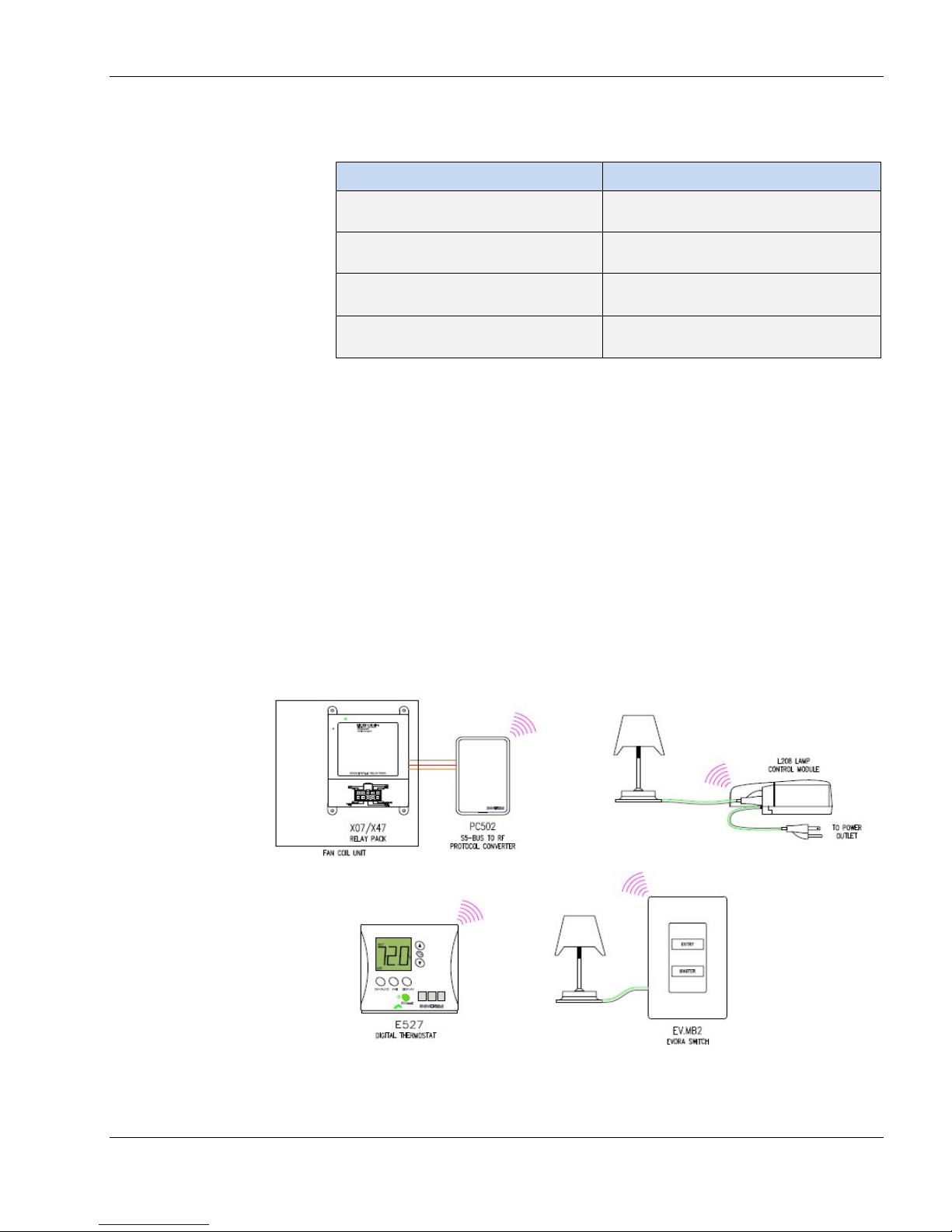
In an in-room application (Appendix 1, Figure 4), the PC-502.1 is providing
S5bus to RF protocol conversion, giving any INNCOM product participating in
the INNCOM Integrated Room Automation System (IRAS) an RF transceiver
for control of wireless products in the guestroom.
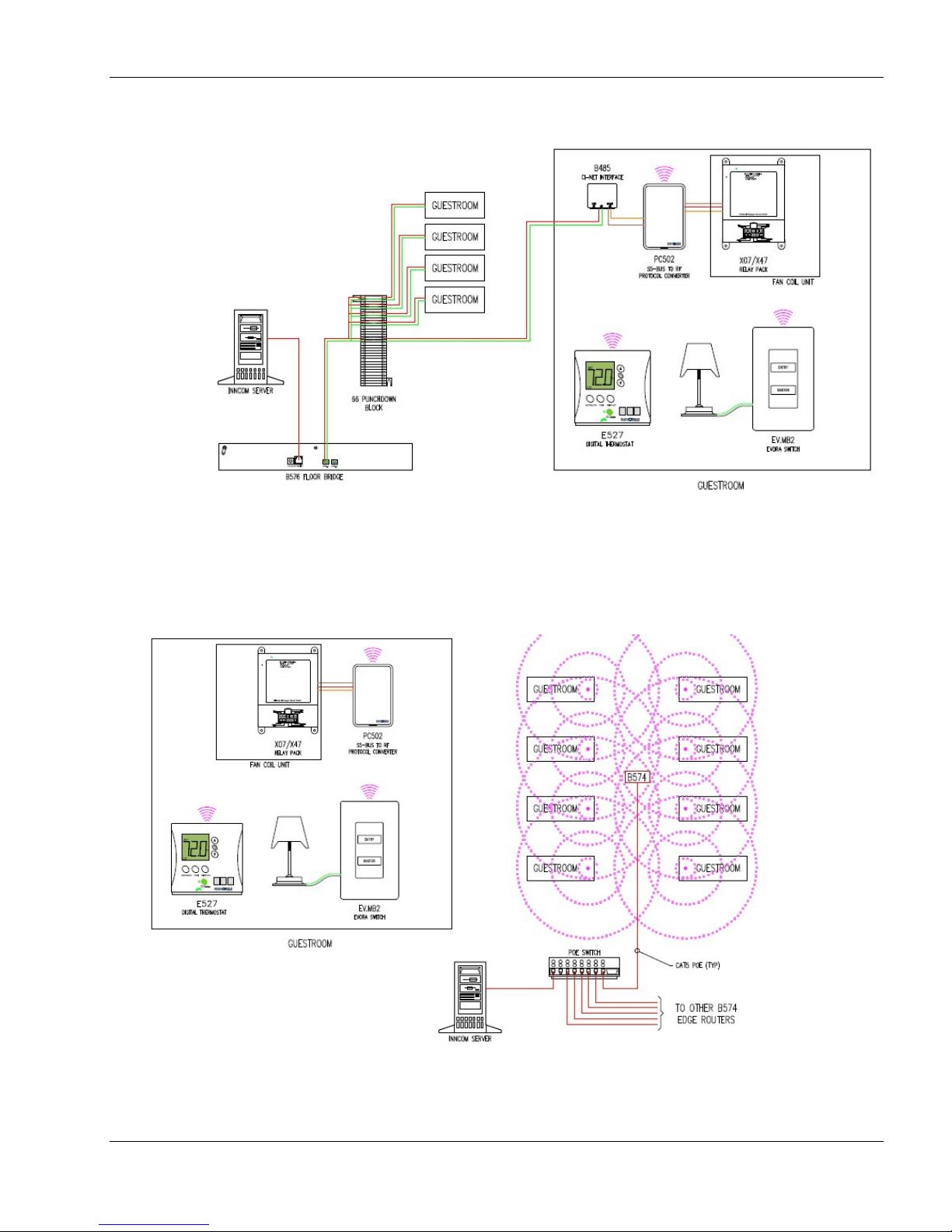
The PC-502 can function as a gateway in an RS485 network as well. Figure 5
in Appendix 1 shows a typical RS485 application.
Rev. 1.6 Date 3/17/2017 3
The PC-502, in participation with the e528, may also provide the in-room to
Deep Mesh RF bridge where both wireless in-room and wireless backend
networking are required. The PC-502 can also patch areas within the Deep
Page 4
PC-502 Module Product Guide
Safety/Regulatory
Mesh network where signal strength is lost due to distance limitations or
interference. Figure 6 in Appendix 1 illustrates a typical PC-502 Deep
Mesh application.
Parameter
FCC
Condition
Part 15b
Status
02-9994, 02-9894 and
029927 are FCC listed.
FCC ID: GTC202124TXR (PC-502.1)
FCC ID: GTC202125TXR (PC-502.2)
This device complies with part 15 of the FCC Rules. Operation is subject to the
following two conditions: (1) this device may not cause harmful interference,
and (2) this device must accept any interference received, including
interference that may cause undesired operation.
This equipment has been tested and found to comply with the limits for a Class
B digital device, pursuant to Part 15 of the FCC Rules. These limits are
designed to provide reasonable protection against harmful interference in a
residential installation. This equipment generates, uses and can radiate radio
frequency energy and, if not installed and used in accordance with the
instructions, may cause harmful interference to radio communications.
However, there is no guarantee that interference will not occur in a particular
installation. If this equipment does cause harmful interference to radio or
television reception, which can be determined by turning the equipment off and
on, the user is encouraged to try to correct the interference by one of the
following measures:
Rev. 1.6 Date 3/17/2017 4
• Reorient or relocate the receiving antenna.
• Increase the separation between the equipment and receiver.
• Connect the equipment into an outlet on a circuit different from that to which
the receiver is connected.
• Consult the dealer or an experienced radio/TV technician for help.
Any changes or modifications not expressly approved by the party responsible
for compliance could void the user's authority to operate this equipment.
IC: 1609A-202124TXR (PC-502.1)
IC: 1609A-202125TXR (PC-502.2)
This Class B Digital Apparatus complies with Canadian ICES-0003. Operation
is subject to the following two conditions: (1) this device may not cause
interference, and (2) this device must accept any interference, including
interference that may cause undesired operation of the device.
Page 5
PC-502 Module Product Guide
-
-
-
44mm
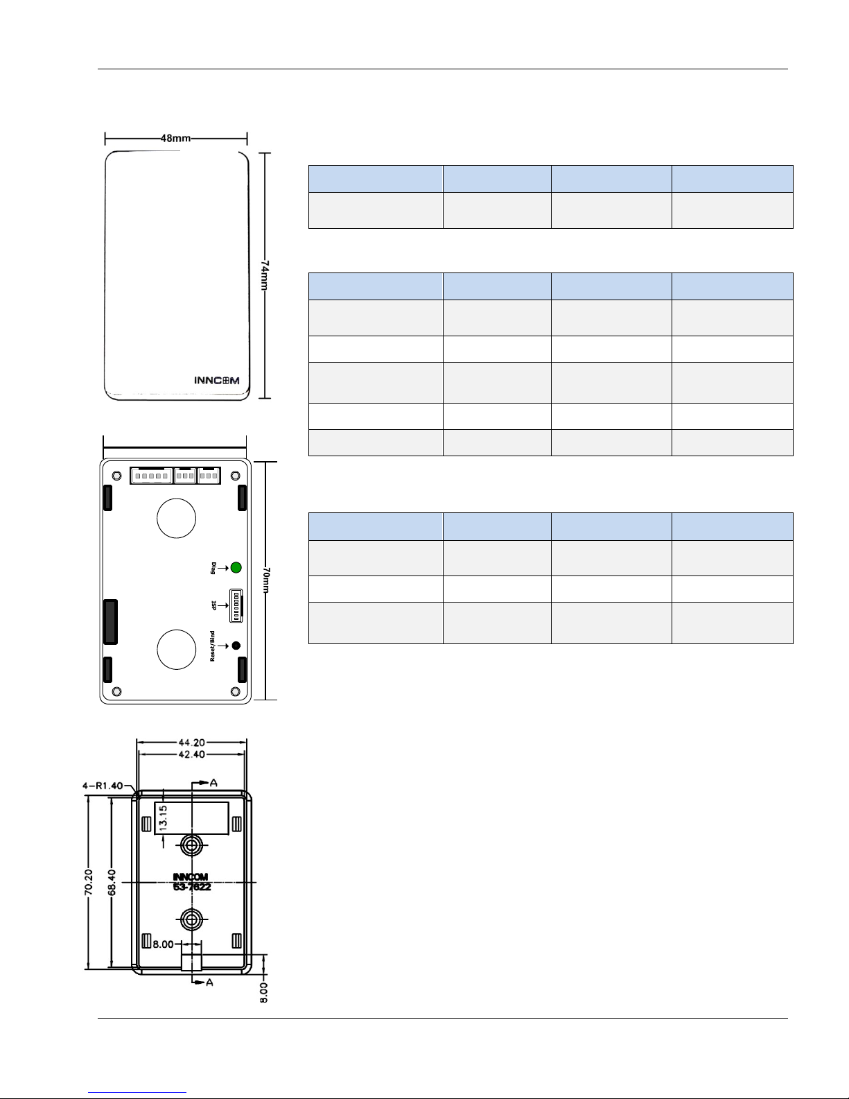
Figure 1 PC-502 Front
Figure 2 PC-502 Back
H2 System-5 H3 S5-bus H4 S5-bus
PC-502 Dimensions Input/Output
H1 (In System Programming)
Pin
1-8 Programming - -
Function
H2 (System 5)
Pin Function Type Max
1-GND Common -
2012VDC Input Voltage In
3-S5bus
Multi Drop
InOut 1 TTL In/Out
5-InOut2 TTL In/Out
H3 / H4 (S5bus In/Out)
Pin
1-GND Common -
In/Out -
Function
Type
Type
Max
11.75/12.25
4
-
-
Max
2012VDC Input Voltage In
3-S5bus
Multi Drop
In/Out -
11.75/12.25
Binding
The PC-502 uses reverse binding to acquire the information necessary to
participate in a network application. The device must signal that it’s
prepared to accept the networking information from the thermostat.
Binding with e528.4G
1. Enter the Service Mode on the e4 thermostat
a. Press and hold the °F/°C button
b. Press and release the OFF/AUTO button
c. Press and release the DISPLAY button
d. Release the °F/°C button)
Rev. 1.6 Date 3/17/2017 5
4
Page 6

PC-502 Module Product Guide
2. Set Room ID (rId) in the e528
a. Press DISPLAY; the current rId will scroll across the screen. Note: If
a value other than rId appears, use the UP/DOWN buttons to scroll
through the values.
b. The upper digit (“HI”) of the Room ID should appear. Use
UP/DOWN to change the value (0–6). Press OFF/AUTO to set.
c. Middle 2 Room ID digits (“MED”) should appear. Use UP/DOWN to
change the value; use OFF/AUTO to set.
d. Last 2 Room ID digits (“LO”) should appear. Use UP/DOWN to
change value; use OFF/AUTO to set.
e. Press DISPLAY to store values. New Room ID should scroll across
LCD.
3. Set PAN ID (PAn) in the e528.
a. In Service Mode, scroll to PAn. Press DISPLAY. Current PAn should
appear on the LCD.
b. Use UP/DOWN to change the PAN ID value (in decimal notation).
c. Press DISPLAY to store the new value. A buzzer will sound on the
e528 to signal that the PAN ID has been set.
4. Set the RF Channel (rF) in the e528
a. In Service Mode, scroll to rf; press DISPLAY. The current channel
should appear on the LCD.
b. Use UP/DOWN to change the rF value.
c. Press DISPLAY to store the new value. A buzzer will sound on the
e528 to signal that the RF Channel has been set.
Binding with e529.RF
1. Enter the Service Parameter mode as described above for
the e528.4G.
a. Set Room ID (rId) in the e529
b. Press OFF/AUTO; the current rId will scroll across the screen. Note: If
a value other than rId appears, use the UP/DOWN buttons to scroll
through the values.
c. The upper digit (“HI”) of the Room ID should appear. Use UP/DOWN
to change the value (0–6). Press DISPLAY to set.
Rev. 1.6 Date 3/17/2017 6
d. Middle 2 Room ID digits (“MED”) should appear. Use UP/DOWN to
change the value; use DISPLAY to set.
e. Last 2 Room ID digits (“LO”) should appear. Use UP/DOWN to
change value; use DISPLAY to set.
Page 7

PC-502 Module Product Guide
f. The new Room ID should scroll across LCD.
2. Set PAN ID (PAn) in the e529.
a. In Service Mode, scroll to PAn. Press OFF/AUTO. Current PAn
should scroll across LCD.
b. Use UP/DOWN to change the PAN
ID value (in decimal notation).
c. Press DISPLAY to store the new value. A buzzer will sound on the
e529 to signal that the PAN ID has been set.
d. Set the RF Channel (rF) in the e529
e. In Service Mode, scroll to rf; press OFF/AUTO. The current channel
value will scroll across the LCD.
f. Use UP/DOWN to change the rF value.
g. Press DISPLAY to store the new value. A buzzer will sound on the
e529 to signal that the RF Channel has been set.
Binding the Device
1. The PC-502.4G uses a “reverse binding” procedure to acquire network
information from the thermostat, meaning that the device will signal the
thermostat that it wants the information. Besides the information set in
the thermostat in the steps above, the PC502 requires a map of
network components, complete with unique address. This information is
typically carried in the I/O Map.
2. Place the thermostat in Service Parameter mode as above. Go to the Io
(I/O Map Teach) parameter and press the DISPLAY button (for
e528.4G) or OFF/AUTO (e529.RF) to view the value. Set the Io value to
the desired I/O Map number. Do NOT press the thermostat’s DISPLAY
or OFF/AUTO button. See I/O Map tables below.
3. For the e528.4G, press OFF/AUTO and the LCD will display bnd. For
the e529, do nothing.
4. Using a small point (e.g., the end of a straightened paper clip), press
the recessed Reset/Bind switch on the PC502 once.
5. The thermostat sends a bind offer to the PC-502. If accepted, the
thermostat will buzz loudly. The PC-502 will reset.
6. Test the PC-502 functionality.
Rev. 1.6 Date 3/17/2017 7
Page 8
PC-502 Module Product Guide
Figure 4
PC-502 In-Room Network
Ordering Information
Model # Description
PC-502 I/O Maps
Appendix 1
201-502.1.WH.P
201-502.1.BK.P
201-502.2.WH.P
201-502.2.BK.P
Protocol Converter PC502: 0dB radio;
White housing
Protocol Converter PC502: 0dB radio;
Black housing
Protocol Converter PC502: 20dB radio;
White housing
Protocol Converter PC502: 20dB radio;
Black housing
Default PC-502 I/O Maps Deep Mesh Gateway
Deep Mesh Room Gateway - Default I/O Map - 0 or 227
Rental/Room Gateway/CELS/Network ID servers enabled
Default PC-502 I/O Maps S5bus converter
RF to S5bus converter only. No 1 or 216 servers enabled
Rev. 1.6 Date 3/17/2017 8
Page 9
PC-502 Module Product Guide
Figure 5
PC-502 RS-485 Network
Figure 6
PC-502 Deep Mesh Network
Rev. 1.6 Date 3/17/2017 9
Page 10
PC-502 Module Product Guide
Revision
Date issued
Reason for change
V0.01
27-Mar-2009
FCC for PC 502
V0.02
31-Mar-2009
Edited for content and format
V1.0
7-Apr-2009
Released
V1.1
18-Feb-2010
Revised with new 2010 FCC statement
V1.1
7-April-2010
Revised to update with PC-502.IR
V1.2
19-July-2013
Reconciled OPN with SAP.
V1.4
29-Aug-2013
Format to Honeywell add 4.G
V1.5
20-Dec-2015
Fixed Binding Information
V1.6
17-MAR-17
Reformat to Honeywell Standard
Document Revision History
The material in this document is for information purposes only. The content and the product it describes
are subject to change without notice. Honeywell makes no representations or warranties with respect to this document.
In no event shall Honeywell be liable for technical or editorial omissions or mistakes in this document, nor shall it be liable
for any damages, direct or incidental, arising out of or related to the use of this document. No part of this document
may be reproduced in any form or by any means without prior written permission from Honeywell.
Copyright © 2017 by Honeywell International, Inc. All Rights Reserved.
Honeywell l 277 West Main Street l Niantic, CT 06357 l Phone: 1.860-739-4468 l www.inncom.com
Rev. 1.6 Date 3/17/2017 10
 Loading...