

Page 1
Gas Detection
OELD
Smart Junction Box
Operating Instructions
Page 2

Contents
2
1 Safety .............................................................................. 3
1.1 Safety Warnings and Information .................................................3
1.2 Disposal ....................................................................................................3
1.3
Waste Elec trical and Electronic Equipment (WEEE ) Directive
1.4 Important Information .......................................................................4
......3
2 Overview ........................................................................ 5
2.1 Introduction ............................................................................................5
2.2 Optional Accessories ..........................................................................6
2.2.1 Pipe Mount Kit (1226A0358) .......................................................6
2.2.2 Ceiling Mount Bracket Kit (1226A0355) ................................7
2.2.3 Sunshade (94000A1006) ..........................................................7
3 Installation .................................................................... 8
3.1 Siting and Positioning ........................................................................8
3.2 Mechanical Installation ..................................................................... 8
3.2.1 Installation to a Flat Sur face ..........................................................9
3.2.2 Optional Pipe and Ceiling Mount Installation ........................9
3.2.3 Using the Searchline Excel Mounting Plate.........................10
3.3 Electrical Installation ......................................................................10
4 Electrical Connections ............................................11
4.1 Power Supply ....................................................................................... 16
6 Operation ....................................................................20
6.1 Display ....................................................................................................20
6.1.1 Start-up ..................................................................................................20
6.1.2 Normal Operation ............................................................................ 21
6.1.3 Display Screen ....................................................................................22
6.2 Bluetooth® Communication .........................................................23
6.3
Alternative Communications (SHC1 HandHeld Interrogator)
...23
7 OELD Mobile App .....................................................24
7.1 Installing the Mobile App ............................................................... 24
7.2 Running the OELD Mobile App ...................................................24
7.3 Connecting to OELD Units ............................................................ 25
7.4 Configure the OELD device ..........................................................26
7.5 Optima Plus Configuration ...........................................................26
7.6 Calibration .............................................................................................27
8 Maintenance ..............................................................28
8.1 General ...................................................................................................28
8.2 Display Module Replacement .....................................................28
9 Faults and Warning ..................................................29
10 Specifications ............................................................30
4.2 Cabling Recommendation ............................................................16
4.3 Earth Regimes ....................................................................................16
5 Configuration .............................................................17
5.1 General ................................................................................................... 17
5.1.1 Threshold for Local Alarm Indication ......................................17
5.1.2 mA Input Level Settings .................................................................17
5.1.3 OELD General Display Settings .................................................18
5.2 Configuration Process ....................................................................19
11 Ordering Information ..............................................32
12 Certification and Approvals ..................................33
12.1 EU Declaration of Conformity ..................................................33
12.2 Hazardous Area Certification ...................................................33
12.3 Performance Approvals ............................................................. 34
12.4 Wireless Approvals ....................................................................... 34
13 Warranty Summary ..................................................36
OELD Op erating Inst ructions
Page 3

1 Safety
1 Safety
1.1 Safety Warnings and Information
WARNING
1. Installation must be in accordance with the recognized standards of the appropriate authority in the country concerned. For
Europe see EN 6007914 and EN 60079292.
2. Do not open the enclosure when energized or when an explosive atmosphere may be present.
3. Operators should be fully aware of the action to be taken if the gas concentration exceeds the alarm level.
4. Do not modify or alter the construction of the product as essential safety and certification requirements may be invalidated.
5. Access to the interior of the product, when carrying out any work, must be conducted only by trained personnel.
6. Measuring function not approved under ATEX. Do not rely on the OELD display backlight status indication for safety-related
purposes.
3
7. In order to maintain electrical safety, the unit must not be operated in atmospheres of more than 21% oxygen.
1.2 Disposal
Dispose of the product in accordance with local regulations. The materials used are: -
Enclosure Aluminum alloy or SS316
Lid Aluminum alloy or SS316, Glass
1.3 Waste Electrical and Electronic Equipment (WEEE) Directive
This symbol indicates that this product and/or parts of the product may not be treated as household or municipal
waste. Waste electrical products (end of life) should be recovered/recycled where suitable specialist WEEE disposal
facilities exist. For more information about recycling of this product, contact your local authority, our agent/
distributor or the manufacturer.
OELD Op erating Inst ructions
Page 4

1 Safety
1.4 Important Information
This manual is for use with the OELD smart junction box only.
Honeywell Analytics can take no responsibility for installation and/or use of its equipment if not done so in accordance with the
appropriate issue and/or amendment of the Operating Instructions.
The reader of these Operating Instructions should ensure that it is appropriate in all details for the exact equipment to be installed
and/or operated. If in doubt, contact Honeywell Analytics for advice.
The following types of notices are used throughout these Operating Instructions:
WARNING
Identifies a hazardous or unsafe practice which could result in severe injury or death to personnel.
Caution
Identifies a hazardous or unsafe practice which could result in minor injury to personnel, or product or property damage.
Note
4
Identifies useful/additional information.
Every effort has been made to ensure the accuracy of this document, however, Honeywell Analytics can assume no responsibility for
any errors or omissions in this document or their consequences.
Honeywell Analytics would greatly appreciate being informed of any errors or omissions that may be found in the content of this
document.
For information not covered in this document, or if there is a requirement to send comments/corrections about this document, please
contact Honeywell Analytics using the contact details given on the back page.
Honeywell Analytics reserve the right to change or revise the information supplied in this document without notice and without
obligation to notify any person or organization of such revision or change. If information is required that does not appear in this
document, contact the local distributor/agent or Honeywell Analytics.
OELD Op erating Inst ructions
Page 5

2 Overview
2 Overview
2.1 Introduction
OELD is hazardous location certified junction box for use with sensors that feature a 420 mA output. The OELD unit has been
designed to operate with the Searchpoint Optima Plus or Searchline Excel range of gas detectors. It provides a local visual status
indication, and a Bluetooth® low energy interface for configuration and maintenance using a Bluethooth®-enabled mobile device.
The OELD unit is ATEX and IECEx approved for use in either Zone 1 (gas) or Zone 21 (dust) hazardous areas as well as being cULus
approved for use in Class I Division 1 or Class II Division 1.
The OELD unit has five entries – either M25 or 3/4” NPT (dependent on the version) and is supplied with three certified blanking
plugs.
WARNING
5
The plastic transport caps supplied must be replaced with a sensor or suitably certified closers (such as glands or stopping
plugs) prior to commissioning the OELD. Failure to do so presents a potential source of ignition.
Internally, the enclosure features two earth connection points, and an electronics module with two pluggable terminal blocks
for connection of field and sensor wiring. The OELD features a four-color backlight (green, yellow, red and blue), and a custom
7-segment liquid crystal display (LCD). In operation, the LCD backlight provides a status indication as follows:
• Green – Normal operation or Warning
• Yellow – Fault or Inhibit
• Red – Alarm (level is configurable)
• Blue – Bluethooth® pairing / connection
Refer to section 6.1.2 Normal Operation for full details on this feature.
WARNING
Do not rely on the OELD LCD backlight status indication for safety-related purposes.
The OELD is configured using a mobile device (such as smart phone or tablet) over Bluetooth® Low Energy. The following
parameters can be configured:
• Threshold for local alarm notification (red indication)
• 420 mA operational levels for the local display
• Gas name, measurement units and range for local display
• Additionally when using the OELD in conjunction with a Searchpoint Optima Plus or Searchline Excel, the user will be able to gain
full access to all configuration and maintenance parameters of the gas detector.
OELD Op erating Inst ructions
Page 6
WARNING
When operating in the hazardous location, ensure that the mobile device being used is suitably certified for that area.
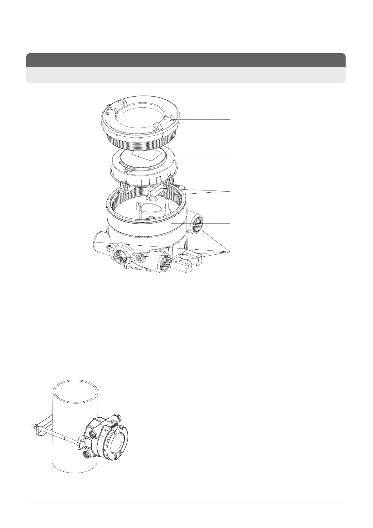
Cover
Electronics module
Terminal blocks
6
Enclosure
Threaded Hole x 5
(M25 or ¾" NPT)
<Figure 1. OELD Exploded View>
2.2 Optional Accessories
Note
The optional pipe mount, ceiling bracket and sunshade accessories are not included as part of the assessment to EN60079291.
2.2.1 Pipe Mount Kit (1226A0358)
The Pipe Mount kit (1226A0358) allows the OELD to be mounted to pipe
from 2” to 6” (50 to 150 mm) in diameter. The kit includes the pipe mount
bracket, two carriage bolts, nuts, and lock washers.
<Figure 2. PipeMounted OELD>
OELD Op erating Inst ructions
Page 7
2 Overview
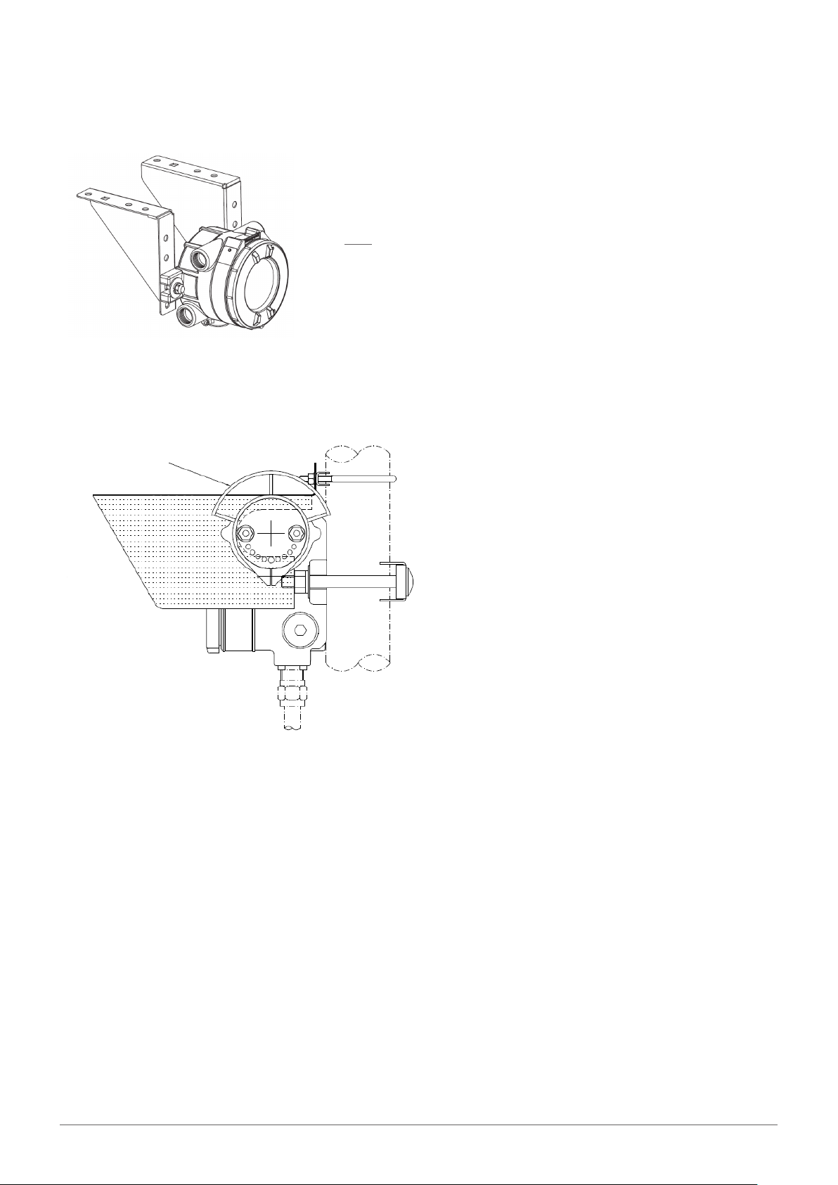
2.2.2 Ceiling Mount Bracket Kit (1226A0355)
The Ceiling Mount Bracket Kit (1226A0355) allows the OELD to be mounted
to the ceiling. The kit includes two stainless steel ceiling mount brackets, bolts,
and nuts.
Note
When considering the final mounting position using the Ceiling Mount
Bracket Kit, consider the ability to see the OELD display when installed.
<Figure 3. CeilingMounted OELD>
2.2.3 Sunshade (94000A1006)
7
SEARCHPOINT OPTIMA
PLUS C /W SUNSH ADE
AND FI TTED TO THE
OELD
<Figure 4. OELD with Sunshade>
A sunshade manufactured from 316 stainless steel, is
available which covers the OELD and can extend over either
side to also provide protection to a Searchpoint Optima or
Searchline Excel
The sunshade slots over the OELD mounting bolts so no
additional fixings are required and is stainless steel 316.
Use the sunshade to reduce the effects of direct solar
heating.
OELD Op erating Inst ructions
Page 8

3 Installation
3 Installation
3.1 Siting and Positioning
The placement of gas detectors should be determined following the advice of:
• experts having specialist knowledge of gas dispersion
• experts having knowledge of the process plant system and equipment involved
• safety personnel
• engineering personnel
The agreement reached on the location of detectors should be recorded.
Guidance on the positioning of gas detectors to provide the best detection coverage is contained in IEC/EN 60079292 and other
national Codes of Practice. It is recommended that the installation designer consults these Codes of Practice when determining
where detectors are to be located.
8
Additionally refer to the technical manual of the gas detector for siting recommendations specific for that device.
3.2 Mechanical Installation
The OELD can be mounted in a number of ways using the integral mounting tabs. The OELD can be attached to flat wall surfaces or
to Unistrut®. With the optional Pipe Mount kit, the unit can be mounted to pipe or pole. A ceiling mount bracket kit (1226A0358) is
also available. If required, conduit (either flexible or rigid) can be run to the OELD.
OELD Op erating Inst ructions
Page 9
3 Installation
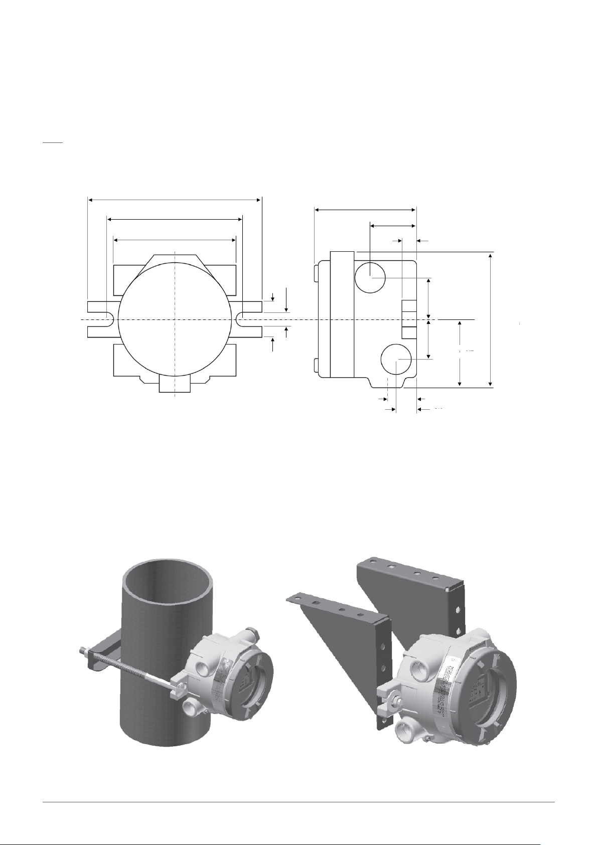
3.2.1 Installation to a Flat Surface
The OELD may be fixed directly to a suitable flat surface, using the integral mounting points (dimensions shown below).
Note
When installing OELD ensure that the correct sensor orientation is considered. Refer to the sensor manufacturer’s instructions.
Ensure that mounting bolts are fully tightened and suitable locking washers are used.
7.8 "
196.9 mm
6.0"
152.4 mm
5.6"
124.2 m m
1.7"
42.4 mm
0.6"
14.4 m m
4.5"
133.8 mm
2.1"
52.2 mm
0.6"
15.9 mm
1.8"
44.9 m m
1.8"
44.9 m m
3.2"
80.7 mm
6.1"
158.78m m
9
1.2"
31.8mm
0.9"
24.0mm
<Figure 5. OELD Dimensions>
3.2.2 Optional Pipe and Ceiling Mount Installation
The OELD may be fixed to a vertical pipe of 2" to 6" (50 to 150 mm) in diameter using the Pipe Mounting kit. This kit (1226A0358)
consists of one bracket, two sets of carriage bolts, nuts and lock washers.
The Ceiling Mount Bracket Kit (1226A0355) allows the OELD to be mounted to the ceiling. This kit includes two stainless steel
ceiling mount brackets, bolts and nuts.
<Figure 6. Pipe and Ceiling Mount Installation Examples>
OELD Op erating Inst ructions
Page 10

3 Installation
3.2.3 Using the Searchline Excel Mounting Plate
The OELD may be fixed to the Searchline Excel mounting plate (2104D0237), which is included in the Searchline Excel kits. Two
M10 tapped holes, ‘K’, are provided for mounting the OELD. Refer to the Searchline Excel technical manual for other details. The
mounting plate fixings are not supplied.
Always mount
plate this way
up
10
<Figure 7. Searchline Excel Mounting Plate>
3.3 Electrical Installation
1. Remove the lid.
2. Lift the handle and take out the electronics module.
3. Fit a suitably approved cable gland or conduit fitting to the required cable entry for the field cable.
4. Fit a sensor to the desired entry referring to the sensor manual for specific information and recommended detector orientation).
Use sealing washers where necessary to maintain the ingress protection rating to IP66/67.
5. Fit suitably certified stopping plugs to all unused cable entries. Use sealing washers where necessary to maintain the ingress
protection rating to IP66/67.
WARNING
The plastic transport caps supplied must be replaced with suitably certified closers (such as glands or stopping plugs) prior to
commissioning the OELD. Failure to do so presents a potential source of ignition.
6. Make the electrical connections (see Chapter 4).
7. Carefully replace the electronics module.
8. Replace and tighten the cover and tighten the locking screw.
Caution
Take care to avoid trapping cables when replacing the display module.
OELD Op erating Inst ructions
Page 11
4 Electrical Connections
4 Electrical Connections
11
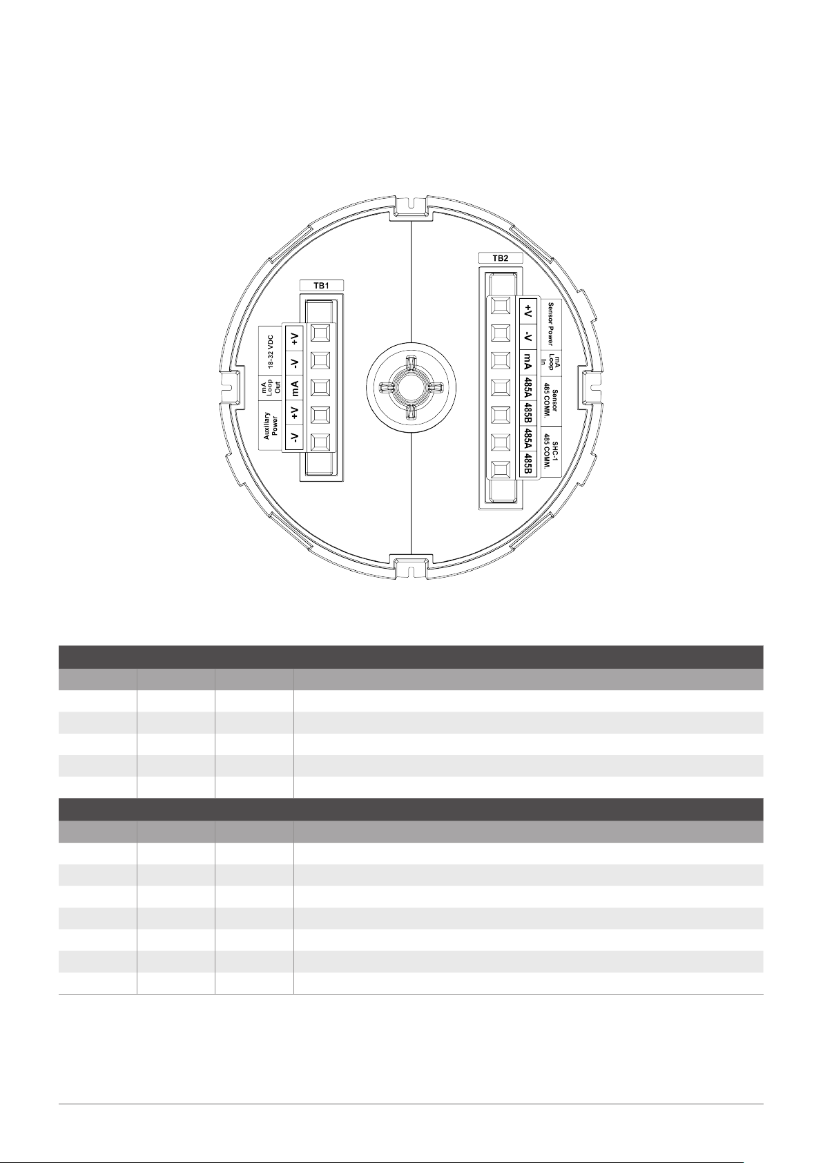
<Figure 8. OELD Electronics Module>
Terminal Block 1 (TB1)
Number Marking Colour Description
1 +V Red Input power +ve
2 V Black Input power 0V
3 mA White mA Signal to Field Wiring
4 +V Red Auxiliary power e.g. Excel cross duct heater
5 V Black Auxiliary power e.g. Excel cross duct heater
Terminal Block 2 (TB2)
Number Marking Colour Description
1 +V Red Sensor power +ve
2 V Black Sensor power -ve
3 mA White mA Signal to gas detector (Optima, Excel, etc.)
4 485A Blue RS485+ to Optima or Excel
5 485B Orange RS485 to Optima or Excel
6 485A Blue Reserved for SHC1 connection
7 485B Orange Reserved for SHC1 connection
OELD Op erating Inst ructions
Page 12
4 Electrical Connections
Caution
When using the SHC1 it must always be connected to the OELD using the SHC Protection Device.
Note
The OELD is protected against accidental reverse polarity connection of power
Spare conductors must be suitably terminated. Wiring must be in accordance with local, national and/or company regulations.
Exposed, bare conductors must be avoided.
The following diagrams show the wiring of the OELD to Searchpoint Optima and Searchline Excel. For other sensors, refer to the
manufacturer’s wiring details.
Caution
The maximum permissible mA loop voltage is 32 VDC and the maximum current is 22 mA.
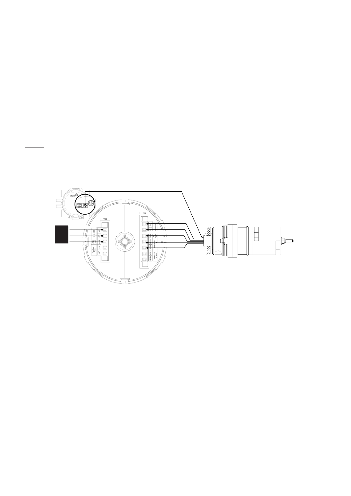
Connecting the OELD to Searchpoint Optima Plus
Green/Yellow (Safety/Protective Ground)
12
Red (+24 Vd c)
Field
Wiring
+24 Vdc in
0 V
42 0 mA
Blac k (0 Vdc)
White (420 mA O utput)
Blue (RS485B)
Orange (RS485A)
OELD
<Figure 9. Wiring Diagram for Searchpoint Optima Plus>
The earth bonding arrangement must ensure that the maximum peak voltage between the unit case earth and any field cable
conductor is less than 350V. Voltages in excess of this can cause permanent damage to the units’ internal RFI protection filters.
OELD Op erating Inst ructions
Page 13

Connecting the OELD to Searchline Excel
Green/Yellow (Safety/Protective Ground)
+24 Vdc in
Fiel d
0 V
Wiring
42 0 mA
OELD
Red (+24 Vd c)
Blac k (0 Vdc)
White (420 mA O utput)
Blue (RS485B)
Orange (RS485A)
4 Electrical Connections
13
<Figure 10. Wiring Diagram for Searchline Excel>
The earth bonding arrangement must ensure that the maximum peak voltage between the unit case earth and any field cable
conductor is less than 350V. Voltages in excess of this can cause permanent damage to the units’ internal RFI protection filters.
Connecting the OELD to Searchline Excel Cross-Duct (XD)
OELD
Green/Yellow (Safety/Protective Ground)
Searc hline Exce l
CrossDuct
Transmitter
Field
Wiring
+24 Vdc in
0 V
42 0 mA
Red (+24 Vd c)
Blac k (0 Vdc)
Green/Yellow
(Safty/Protective Ground)
Blcak o r Brown (+V)
White (0 V )
To He ater
Reflector Panel
Green ( Earth)
Orange (RS485A)
Blue (RS485B)
White ( mA Output )
Searchline
Exce l Cross Duct
Receiver
Blac k (0 Vdc)
Red (+24 Vd c)
<Figure 11. Wiring Diagram for Searchline Excel CrossDuct>
The earth bonding arrangement must ensure that the maximum peak voltage between the unit case earth and any field cable
conductor is less than 350V. Voltages in excess of this can cause permanent damage to the units’ internal RFI protection filters.
OELD Op erating Inst ructions
Page 14

OELD Connection for Sensors Configured as Current Sink
Sensor Controller
<Figure 12. mA Input Sink Configuration>
OELD Connection for Sensors Configured as Current Source
Sensor Controller
4 Electrical Connections
14
<Figure 13. mA Input Source Configuration>
Caution
The maximum permissible mA loop voltage is 32 VDC and the maximum current is 22 mA.
OELD Op erating Inst ructions
Page 15

4 Electrical Connections
SHC-1 Connection
WARNING
Do not Attempt to connect SHC1 Handheld interrogator directly to the OELD. Always use the SHC Protection Device.
Connect the SHC1 Handheld Interrogator to the OELD using the SHC Protection Device.
IS Connector
Flying Lead
<Figure 14. SHC Protection Device>
Note
15
A hot work permit may be required for this procedure.
Carry out the following procedure to connect using the protection device:
1. Isolate all power supplies.
2. Remove the OELD cover
3. Lift out the electronics module and locate the blue and orange terminals market ‘SHC1 485 COMM’
4. Connect the flying leads of the SHC Protection Device to the these terminals as shown:
Brown
Blue
SHC Protection
Devic e Flying Le ad
<Figure 15. Connection for the SHC Protection Device>
5. Connect the SHC1 hand-held interrogator to the IS connector on the end of the SHC Protection Device.
6. Re-apply power.
OELD Op erating Inst ructions
Page 16

4 Electrical Connections
4.1 Power Supply
The OELD requires a voltage supply of 18 - 32 Vdc (nominal 24 Vdc). Power consumption is 2 W maximum.
Refer to individual sensor manuals for sensor specific limits and power consumption.
Ensure that the minimum required supply voltage is present at the sensor, taking into account the voltage drop due to cable
resistance.
Note
Make allowance for the insertion loss resistance.
The maximum loop resistance in the field cable is calculated as follows:
16
V
controller
R
loop
I
detector
V
detector min
4.2 Cabling Recommendation
The cable used must be appropriate for the hazardous area classification and meet local, national and/or company regulations. The
use of industrial grade, screened field cable is recommended.
An example would be 3-core copper cable with screen (minimum 90% coverage) and suitable mechanical protection (e.g. steel wire
armor) to suit an M25 or 3/4”NPT gland entry or conduit.
The allowable conductor size for the terminals is 0.2 – 2.5 mm² (24 - 12 AWG). The OELD terminals will accept only wire sizes(solidcore or stranded) in this range. The temperature rating of the conductors should be greater than 80°C. The terminals should be
torqued between 0.5 Nm to 0.6 Nm.
Ensure the cable gland is installed correctly and fully tightened. All unused cable/conduit entries must be sealed with a suitable
certified blanking plug.
4.3 Earth Regimes
Caution
Any earthing regime employed must avoid earth loops.
The following information is provided to assist with proper earthing of the OELD:
• The OELD has two internal earth points provided (see Electrical Connections). This is to facilitate connection of the sensor to
protective earth.
• Field cable screens should be connected to instrument earth at the control room. The other end of the field cable screen should
be suitably terminated or isolated. It should not be connected to internal earth point.
OELD Op erating Inst ructions
Page 17

5 Configuration
17
5 Configuration
5.1 General
The OELD has several configurable parameters, which are set using a mobile device running the OELD app. Essentially, these are the
threshold for local alarm indication, mA input level settings, Remove RS485 communication settings, behaviour of the green light
and display settings such as full scale range, measurement unit and gas name.
5.1.1 Threshold for Local Alarm Indication
The gas reading at which the the OELD indicates an alarm (flashing red lights) can be set between 5 and 65 % FSD. The default
setting is 20 % FSD.
Note
This setting is local to the OELD and applies only to the red lights in the OELD backlight. Changing the level will have no effect
on alarm levels configured in the sensor, or in the control room.
Note
Guidance for setting alarm levels appropriate for the application can be found in IEC/EN 60079292 and/or other regional and
local publications.
5.1.2 mA Input Level Settings
The sensor transmits a mA output in relation to the measured gas value. Also the mA output is used to provide an indication of the
status of the sensor which can include warning, fault and inhibit. The mA input to the OELD can be configured to match the mA
output profile of the sensor to control the OELD backlight function and show messages on the OELD display. The factory settings
for Searchpoint Optima Plus and Searchline Excel are given in the table below.
Sensor Status
Fault 01 mA 0 mA
Inhibit 2 mA 2 mA
Warning 3 mA N/A
Beam Block N/A 2.5 mA
Low Signal N/A 3 mA
Gas Reading 420 mA 420 mA
OverRange ≥ 21 mA ≥ 21 mA
Searchpoint Optima Plus* Searchline Excel
mA Detection Settings
Note
*Searchpoint Optima Plus with HART® requires a minimum of 1 mA flowing in the current loop for HART® communications to
be maintained. It is possible to set the mA level in the Searchpoint Optima Plus for fault to 1 mA, however this may affect the
reliability of the HART® communications.
To ensure correct reporting of the gas detector status (fault, inhibit, warning and over-range), it is essential that the mA input ranges
are chosen to match those of the connected gas detector. Allow for a separation of at least 0.1 mA between each of the ranges.
OELD Op erating Inst ructions
Page 18

5.1.3 OELD General Display Settings
The user configurable settings of the OELD display are:
• full scale range
• units of measurement
• reading resolution
• gas name
These settings are used to convert the 420 mA output from the sensor into a reading on the OELD display.
WARNING
Do not rely on the OELD LCD backlight status indication for safety-related purposes.
5 Configuration
18
OELD Op erating Inst ructions
Page 19

5 Configuration
19
5.2 Configuration Process
Note
After configuration or making any changes to the OELD or gas detector settings, the configuration should be read back and
verified to ensure that the intended changes have been made.
Configuration of the OELD is achieved through use of a mobile device running the OELD app. There is no local interface to configure
the OELD.
The configuration process involves connecting to the OELD unit via the Bluetooth® (BLE) interface of a suitable smart phone or
tablet. During the connection, the blue light of the OELD will indicate different states. Once the connection has been successfully
established and if the sensor status is normal, the OELD blue light will be lit solid blue to indicate this. Connect the mobile device to
the OELD as follows:
1. Locate the icon for the OELD App on the mobile device and tap on it to start the app
2. Log into the OELD App by entering the registered User ID and Password
3. Search for nearby OELD units
4. Select the desired OELD from the displayed list
5. The backlight of the OELD will flash blue, confirming your selection from step 4
6. Once the user has confirmed the unit, the connection process will complete
7. The OELD App will display information from the OELD on the main status screen.
For more details on the connection procedure refer to section 6.2 Bluetooth® Communication.
Once the OELD is connected to the mobile device, the user can configure the OELD via the menu system of the app. For more
details on the operation of the mobile application, refer to section 7 OELD Mobile App.
After all operations have been completed, simply terminate the connection from the main screen of the app so that other mobile
devices can connect to it.
Caution
Only one Bluetooth® connection is allowed. Terminate the Bluetooth® connection when the configuration activity has been
completed
OELD Op erating Inst ructions
Page 20

6 Operation
6 Operation
6.1 Display
6.1.1 Start-up
The start-up and self-test sequence of the OELD takes approximately 60 seconds. During this time the user can check that each
of the functions listed below are operating correctly as well as the OELD checking the correct operation of its critical circuits and
processes. The OELD will perform a series of functional tests, including:
• Display test – each segment of the LCD will be sequentially activated
• Backlight test – each of the colours of the backlight will be activated several times
• Internal hardware and memory checks
• Display of software version
20
• Display of user-configured settings such as gas name, range and alarm set points
Once the LCD and backlight tests have completed, the green backlight indication will be illuminated for the remainder of the start-up sequence.
Once the OELD has completed this start-up sequence, it will enter its normal operating condition.
<Figure 16. Start-up Sequence>
OELD Op erating Inst ructions
Page 21

6 Operation
Note
Upon completing the start-up sequence, the OELD may momentarily report the status of the sensor as fault, inhibit or warning.
This can be as a result of the sensor connected taking more time to complete its initialization and it holding its output at a level
of less than 4 mA. This is normal.
6.1.2 Normal Operation
During normal operation, the LCD backlight provides an indication of the sensor status based on the sensor 420 mA output as follows:
21
Default Detection Ranges
OELD Backlight
Color Flashing
Typical Status
Less than 1.5 mA Yellow Yes Fault
1.5 to less than 2.5 mA Yellow No Inhibit
2.5 to less than 3.5 mA G Y G Alternating Yellow Warning
3.5 mA to less than Alarm Threshold* Green No Normal
Greater than or equal to Alarm
Threshold*
Red Yes Hazardous Gas Concentration
3.5 mA to less than Alarm Threshold** Blue No Normal, OELD connected to a mobile device
* Alarm threshold is configurable between 5 and 65 % FSD (4.8 mA to 14.4 mA)
Note
The current detection ranges are configurable by the user using the OELD app.
Note
The visual output of the OELD is derived from the 420 mA output of the sensor and/or status of the OELD unit. Use a suitable
mobile device and the OELD app to connect to the OELD using Bluetooth® to access further diagnostic information. When used
in conjunction with a Searchpoint Optima Plus or Searchline Excel, diagnostic and maintenance functions of the sensor can be
accessed also.
OELD Op erating Inst ructions
Page 22

Full scale
Bar Graph
Gas name
Gas Reading
Test Pass Icon Warning/Fault Icon
Inhibit Icon
Alarm Icon
Measurement
Units
BLE Icon
6 Operation
6.1.3 Display Screen
The OELD features a backlit liquid crystal display (LCD) with high-intensity multi-color LEDs to show normal, alarm, fault and
communication status.
During normal operation the instrument LCD shows a steady GREEN backlight. In case of a gas alarm or fault the red or yellow
backlight respectively will flash. The screen is visible through the window of the OELD top cover and the display shows the gas
concentration information both graphically and numerically, as well as other information including full scale range, measurement
units, alarm / fault status etc.
Note
At low temperatures, the OELD automatically lowers the refresh rate of the display to maintain optimal readability.
Note
At extreme low temperatures (typically less than 40°C), a reduction in screen clarity may be experienced. The display module
will not be damaged by this condition and will recover once normal operating ambient temperature has returned.
Test Pas s Icon Warning/Fault Icon
Full Sc ale
Bluetooth
22
Bar Graph
Gas name
Gas Reading
Inhibit Icon
Alarm I con
Measurement
Units
<Figure 17. Display Screen>
OELD Op erating Inst ructions
Page 23

6 Operation
23
6.2 Bluetooth® Communication
The OELD features a Bluetooth® Low Energy (BLE) interface that allows non-intrusive connection to the OELD using a mobile
device running the OELD app. In addition the OELD bridges message transactions between the mobile device and the Searchpoint
Optima Plus or the Searchline Excel by converting the BLE packet information into RS485 messages and relaying them to the RS
485 interface, and vice versa. The OELD does not process, convert or regenerate any RS485 messages between the mobile device
and Searchpoint Optima Plus or Searchline Excel sensors.
The BLE interface is accessed by a suitable mobile device that supports Bluetooth® Low Energy(BLE).
Refer to the OELD Mobile App User Manual for more information on the Bluetooth® the communication link.
Note
• The BLE (Bluetooth® Low Energy) differs from Bluetooth® Classic. Make sure the mobile device selected has an operating
system that supports BLE.
• The Bluetooth® feature should be enabled on the mobile device to allow it to scan BLE devices nearby.
Refer to the User Manual of the mobile device for details of how to use the Bluetooth® functions of the mobile device.
• The OELD supports BLE point-to-point mode of operation. If a connection is established between the OELD and a mobile
device, it cannot be scanned or accessed by another mobile device.
• If there is no active BLE communication for 10 minutes, the OELD will terminate the BLE connection automatically.
• The communication range will vary depending on the field situation and installation location of the OELD. Optimal range will
be achieved line-of-sight between the OELD and the mobile device.
6.3 Alternative Communications (SHC1 HandHeld Interrogator)
If the OELD is being used in conjunction with the Searchpoint Optima Plus or Searchline Excel the sensor can be accessed using the
Honeywell Analytics SHC1 Handheld Interrogator and the SHC Protection Device. Use the dedicated terminals inside the OELD to
do this.
Caution
The SHC1 must be not be directly connected to the terminals inside the OELD. Always use the SHC protection device (part no.
04230A1025)
WARNING
Do not use Bluetooth® communication when using the SHC1 Hand-held Interrogator.
Note
The SHC1 has not been evaluated for gas performance in accordance with ISA 60079291(12.13.01).
Refer to the Searchpoint Optima Plus or Searchline Excel manual for details of how to use the SHC1 Handheld Interrogator.
OELD Op erating Inst ructions
Page 24

7 OELD Mobile App
7 OELD Mobile App
7.1 Installing the OELD App
The OELD Mobile App running on the mobile device is used to configure the OELD and the Searchpoint Optima Plus or Searchline
Excel that is connected to it. The OELD App runs under the Android Operating System (OS) version 4.3 (Jelly Bean) or higher that
supports Bluetooth ® Low Energy (BLE). The OELD App is available for download from the Google Play Store.
To install the app:
1. Start and sign in to the Google Play Store
2. Search for “Honeywell OELD App” and click on INSTALL
3. The Mobile App will be automatically downloaded and installed on the mobile device.
24
7.2 Running the OELD Mobile App
Note
To register a new user account you will need 1) a connection to the internet and 2) the QR code from at least one OELD device.
1. Find and tap the OELD App icon
2. Upon first start-up the app will prompt the user to read the End User License Agreement. Please take time to read this and
accept to proceed.
3. The log-in screen will appear and ask the user to log in the app
4. If you are already a registered user, enter your log-in details.
5. If you do not have a registered user account, please complete and submit the registration form in the app. Shortly afterwards you
will receive a confirmation e-mail. Click on the link in the email complete the email verification process.
6. Locate the Registration Sheet supplied with the OELD. This will have a QR code on it. Scan the QR code supplied to complete the
registration process. Alternatively scan The QR code can also be found on the rear face of the electronics module.
7. Upon scanning the QR code, the security certificate will be downloaded from the Honeywell server.
OELD Op erating Inst ructions
Page 25

7 OELD Mobile App
25
7.3 Connecting to OELD Units
1. Standing in proximity to the OELD to which you want to connect, tap on the Detectors button on the main screen of the OELD
App
2. A list of detectors to which you have access will be shown. Should you require access to a detector that is currently restricted, tap
on the device and simply scan the QR code of that device. This can be found on both the Registration Sheet that was supplied
with the detector and on a label attached to the side of the electronics module
3. Follow the on-screen prompts and click on Confirm Detector to complete the connection process
4. Once connected to the OELD, it is possible to configure it and the Searchpoint Optima or Searchline Excel gas detector that is
connected to it.
Main Screen Detector List Example :
Available Devices
Confirming Detector
Device Main Screen Configure Screen
flashing Blue
Note
A user can connect to any OELD devices that have been registered to the user account.
Detector List Example :
Prohibited Devices
For detailed configuration procedure using a mobile device, refer to OELD App User Manual or the on-line help of the OELD App.
OELD Op erating Inst ructions
Page 26

7 OELD Mobile App
7.4 Configure the OELD device
The OELD has several configurable parameters, which can be set using mobile device and OELD App. The configurable parameters
are shown in the table below.
Configuration Parameters Default Setting Other Options
Device type Searchpoint Optima Plus Searchline Excel / Generic 4 to 20mA transmitter
Alarm Threshold* 20% Any value between 5 and 65 % FSD
Gas name on display ‘FLm’ 4 of User-configurable alpha-numeric characters
Display resolution 1 Decimal places (e.g. 0.1)
Full Scale Range for 20 mA 100 Depends on the display resolution
Measurement units %LEL %Vol, mg/m3, g/m3, ppm, kppm, ppm·m, LEL·m, mA, A, dB, dBA
Inhibit Current 1.5 to 2.5 mA 0 to 3 mA
Warning Current 2.5 to 3.5 mA 0 to 6 mA
Beam block current 2.3 to 2.7 mA 0 to 6 mA
Over-range Current 20.0 to 24.0 mA 20 to 24.0 mA
Normal (Green) LED control On Off
26
Note
Alarm threshold and trigger relates to the local indication of the LED only. These settings do not affect the operation of the
connected sensor or any other systems connected to the OELD.
7.5 Optima Plus Configuration
The OELD Mobile App allows a user to configure a Searchpoint Optima Plus gas detector that is connected to the OELD unit. The
configurable parameters are as shown in the table below.
Configuration Parameters Min Value Max Value Step Size
Alarm Threshold 10% 65% 1%
Inhibit Current* 0mA 3mA .05mA
Warning Current* 0mA 6mA .05mA
Over-range Current 20mA 21.6mA .05mA
*to ensure full compliance with the requirements of ATEX, refer to the Searchpoint Optima Plus manual for appropriate settings
when using this gas detector.
Note
Make sure the RS485 connections are made between the Searchpoint Optima Plus and the OELD.
OELD Op erating Inst ructions
Page 27

7 OELD Mobile App
27
7.6 Calibration
The OELD App allows a user to calibrate the Searchpoint Optima Plus or Searchline Excel. Note that this feature is not available for
other gas detectors or sensors that may be used.
Caution
Searchpoint Optima Plus is factory calibrated and does not require routine calibration. In most cases, a re-zero will correct any
inaccuracy in the gas reading. It is strongly recommended that a span calibration is not carried out.
After establishing a connection between the mobile device and the OELD, tap on the Calibrate button on the main screen of the
OELD App.
1. Ensure that the gas detector is in fresh air and tap on the Zero button to start the zero calibration process
2. The OELD App will automatically inhibit the gas detector and initiate the zero calibration.
3. After a successful zero calibration has been completed a span calibration may be performed. Tap on the Span button to perform
a span calibration and complete steps 4 and 5 below. Otherwise tap on Exit Without Span to exit and ignore steps 4 and 5.
4. Apply calibration gas to the Searchpoint Optima Plus
5. Follow the on-screen prompts and wait until span calibration is complete
Refer to the Searchpoint Optima Plus or Searchline Excel Technical Handbook for full details on carrying out gas calibrations.
WARNING
• As some calibration gases may be hazardous, always ensure that outlets from gassing accessories exhaust safely.
• A cylinder of synthetic air (20.9 % vol. oxygen) should be used to perform the zero calibration if there is any doubt that the
atmosphere in which the detector is exposed may contain any trace of detectable gas.
OELD Op erating Inst ructions
Page 28

8 Maintenance
8 Maintenance
8.1 General
Periodically inspect the OELD and cabling for signs of physical damage. Clean the glass window with a damp cloth. Do not use
solvents or abrasive cleaners.
The OELD has no user serviceable parts. Honeywell Analytics recommend that the unit’s configuration and operation are checked
annually as a minimum.
The gas detectors connected to the OELD should be checked and if necessary zero and span calibrated as necessary by following
the procedures detailed in their operating instructions.
28
8.2 Display Module Replacement
In the unlikely event of failure, the electronics module can be replaced.
Caution
In addition to the instruction below, always observe company and site procedures with respect to working on equipment in the
hazardous area.
1. Remove the power from the OELD. Loosen the lock screw using the tool provided and carefully unscrew and remove the cover.
2. Lift the handle and take out the internal electronics module taking care not to place any undue strain on the connected cables.
3. Loosen the locking screws of the terminal blocks and unplug them from the underside of the module
4. It is recommended to record the serial number of the original electronics module and mark that serial number inside the
enclosure. In addition, retain a record of the original serial number of the module in the maintenance record for that installation.
5. Remove the terminal blocks from the replacement electronics module and plug in the original terminal blocks and wiring. Secure
using the locking screws. Should the OELD require rewiring, refer to Chapter 4 Electrical Connections.
6. Carefully replace the display module taking care not to place endue strain on the attached wiring.
7. Fully tighten the cover.
Caution
Take care to avoid trapping cables when replacing the display module.
Note
The replacement electronics module will have default settings for the threshold for local alarm indication and mA input level
settings, RS485 communication settings, visual indicator and sensor settings. Use the OELD App to make changes that are
necessary.
OELD Op erating Inst ructions
Page 29

9 Faults and Warning
9 Faults and Warning
Display Message Code Description Remedial Action
Over-range warning. The output from
Over Rang W01
bEAm Bloc W02* Beam block signal detected
the connected sensor is indicating a
gas reading greater than the full-scale
deflection.
Proceed with extreme caution as there may be
a dangerous level of gas present. If the warning
persists, check the sensor by referring to the sensor
manual. Check the sensor by referring to sensor
manual
The connected Searchline Excel is indicating that
the there is an obstruction between the transmitter
and receiver or that the signal is being excessively
attenuated. Refer to the Searchline Excel manual
29
Warn W03 Warning level input from the detector
Comm Err F01 Internal communication failure
FLt F02 Fault level input from the detector Refer to the sensor manual for further information.
LooP High F03 Input current is too high
Volt Err F04
RAM Err F05 RAM read/write fault
Mem Err F06
Code Err F07 Code Memory corrupted
Cert Err F08 Device certificate corrupted Contact the manufacturer
Note
Supply voltage fault or Internal power
supply fault
An internal memory corruption has
been detected
Refer to the sensor manual for further information
and possible causes.
Reset the OELD. If fault still appears, replace the
display module
The output from the connected sensor is exceeding
the upper input range of the OELD. Check the sensor
by referring to sensor manual
Check the input voltage to the OELD. Reset the
OELD. If fault still appears, replace the power module
Reset the OELD. If fault still appears, replace the
display module
Reset the OELD. If fault still appears, replace the
display module
Reset the OELD. If fault still appears, replace the
display module
Warning for Beam Block (W02) is only applicable when the connected sensor type is Searchline Excel.
OELD Op erating Inst ructions
Page 30

10 Specifications
OELD Specification
Material Marine-grade aluminum alloy or 316 stainless steel with 5-coat painted finish
Weight Aluminum version 2.3 kg (5 lb), stainless steel version 5.0 kg (11 lb)
Dimensions 159 x 197 x 114 mm (6 ¼ x 7 ¾ x 4 ½ inch)
10 Specifications
30
Cable entries
Termination
Storage Temperature 40 to +65 °C (13 to 149 °F)
Operational temperature
Humidity 0 to 99% RH (non-condensing)
Display Information
Visual indication
Power supply 18 to 32 Vdc (24 Vdc nominal), <2 W
Interfaces
5 x M25 (ATEX/IECEx version) or 5 x ¾” NPT (cULus version). One reserved for sensor connection. 3
blanking plugs supplied for unused entries.
2 x pluggable rising-clamp type for connection to gas detector and field wiring. Accepts cable sizes of
0.5 to 2.5 mm², 12 to 28 AWG
40 to +65 °C (40 to 149 °F)
60 to +65 °C (76 to 149 °F) (CU TREx version only)
LCD module showing digital readout of sensor output, bar chart representation, units of measurement,
status icons for alarm, maintenance and active Bluetooth connection. Display units, range and gas
name, all configurable using the App.
Green/amber/red/blue multi-colour backlight to display for indication of detector and OELD status.
Green (normal) indication can be disabled via app.
Bluetooth® (BLE) non-intrusive connection to suitable mobile device running the OELD App. Range
up to 10 m (depends on mobile device and environmental conditions)
Internal RS485 connection to Searchpoint Optima Plus or Searchline Excel via SHC1 through the
protection device
Environmental Protection IP66 / Type 4X(in accordance with NEMA 250)
Core Approvals
+flameproof versions only
EN 50270:2015 (EMC)
IEC/EN/UL/CSA 610101 (Electrical Safety)
OELD Op erating Inst ructions
Page 31

Safety Approvals
OELD Specification
ATEX [DEMKO 16 ATEX 1693X]
II 2 GD
Ex db IIC T6 (flameproof Ex d version)
Ex tb IIIC T85°C (flameproof Ex d version)
Tamb 40 to +65°C
cULus [E484838]
Class I, Division 1, Groups A, B, C and D
Class II, Division 1, Groups F and G
Class III, Division 1
Tamb 55 to +65°C, Temp Code T6, IP66, Type 4X
Class I, Zone 1, AEx d IIC T6
Class I, Zone 21, AEx tb IIIC T6
IECEx [IECEx UL 16 0066X]
Ex db IIC T6 (flameproof Ex d version)
Ex tb IIIC T85°C (flameproof Ex d version)
Tamb 40 to +65°C
CU TREx (Russian Customs Union), Tamb 60 to +65°C*
CCCF*
Inmetro [DNV 17.0010X]*
NEPSI+*
ISA 60079291
EN60079291 approved accessory
10 Specifications
31
Type approved to DNV, BV+, Lloyds+, ABS
Maritime Approvals*
EN 60945 (EMC)
IEC 60092504
Other Approvals Bluethooth® certified, RED, FCC+, country-specific wireless approvals
Bluetooth®
communication security
Certificate-based mutual authentication. Encryption to AES128.
Note
+flameproof versions only
*Contact Honeywell Analytics for availability
Gas Performance: ISA 60079291 approved for methane gas only
OELD Op erating Inst ructions
Page 32

11 Ordering Information
11 Ordering Information
Part Number Description
OELDBXXXXXADMAX OELD Smart Junction Box, Display, Ex d, Aluminum, 5 x M25 Cable Entries, ATEX/IECEx
OELDBXXXXXSDMAX OELD Smart Junction Box, Display, Ex d, Painted 316SST, 5 x M25 Cable Entries, ATEX/IECEx
OELDBXXXXXAEMAX OELD Smart Junction Box, Display, Ex e, Aluminum, 5 x M25 Cable Entries, ATEX/IECEx
OELDBXXXXXSEMAX OELD Smart Junction Box, Display, Ex e, Painted 316SST, 5 x M25 Cable Entries, ATEX/IECEx
OELDBXXXXXADNUX OELD Smart Junction Box, Display, C1D1 Z1, Aluminum, 5 x 3/4" Cable Entries, cULus
OELDBXXXXXSDNUX OELD Smart Junction Box, Display, C1D1 Z1, Painted 316SST, 5 x 3/4" Cable Entries, cULus
OELDBXXXXXADMRX OELD Smart Junction Box, Display, Ex d, Aluminum, 5 x M25 Cable Entries, CUTR Ex
OELDBXXXXXSDMRX OELD Smart Junction Box, Display, Ex d, Painted 316SST, 5 x M25 Cable Entries, CUTR Ex
OELDVSK01 OELD General Service Kit
OELDVSK02 OELD Terminal Block Set for flameproof versions
32
OELDVSK03 OELD Terminal Block Set for increased safety versions
OELDVSK04 Stopping plug for M25 versions
OELDVSK05 Stopping plug for NPT versions
OELDVSK06 Electronics Module for flameproof versions
OELDVSK07 Electronics Module for increase safety versions
OELDVSK08 Electronics Module Locating Post
1226A0358 OELD Pole Mounting Kit
1226A0355 OELD Ceiling Mounting Kit
94000A1006 OELD Sunshade Kit
OELD Op erating Inst ructions
Page 33

12 Certification and Approvals
12 Certification and Approvals
12.1 EU Declaration of Conformity
A full EC declaration of conformity is included with the product. This document lists the European Standards with which the OELD
smart junction box complies.
12.2 Hazardous Area Certification
Special conditions for safe use
Please confirm that these are ALL of the ATEX Special Conditions of Safe Use are listed here. We cannot check here since we don’t
have the certificate.
33
To minimize the risk of electrostatic charge, provisions shall be made for an adequate grounding of the equipment, including
accessories (e.g. sunshade). Equipment shall be installed in a manner so that accidental discharge shall not occur.
12.2.1 ATEX
Certificate Number: DEMKO 16 ATEX 1693X
II 2 GD
Ex db IIC T6
Ex tb IIIC T85 °C
Tamb 40 to +65 °C
IP 66
Vmax = 32 Vdc, Pmax = 2 W
12.2.2 IECEx
Certificate Number: UL 16.0066X
Ex db IIC T6 (flameproof Ex d version)
Ex tb IIIC T85°C (flameproof Ex d version)
Tamb 40 to +65 °C
OELD Op erating Inst ructions
Page 34

12.2.3 cULus
Certificate Number: E484838
Class I, Division 1, Groups A, B, C and D
Class II, Division 1, Groups F and G
Class III, Division 1
Tamb 55 to +65 °C, Temp Code T6, IP66, Type 4X
Class I, Zone 1, AEx d IIC T6
Class I, Zone 21, AEx tb IIIC T6
12.2.4 Inmetro
Certification Number: DNV 17.0010X
12.3 Performance Approvals
12.3.1 ATEX
12 Certification and Approvals
34
Assessed as an approved accessory for use with Searchpoint Optima Plus
Note
The optional pipe mount, ceiling bracket and sunshade accessories are not included as part of the assessment to EN60079291.
12.3.2 cULus
ISA 60079291
Certificate Number: E484838
WARNING
1. Model OELD Smart Junction Box has been evaluated for gas performance testing in accordance with ISA 60079291
(12.13.01) for Methane gas only.
2. Model OELD Smart Junction Box has been evaluated for gas performance testing in accordance with ISA 60079291
(12.13.01) for use as a stand-alone controller only.
3. Model OELD Smart Junction Box has been evaluated for gas performance testing in accordance with ISA 60079291
(12.13.01) for %LEL display options only. The mg/m3, g/m3, %Vol, ppm, mA, A, kppm, %LEL-m, LEL-m, dB, dBA, and
ppm-m display options have not been evaluated, and shall not be used for ISA 60079291 (12.13.01) installations.
4. Do not use Bluetooth communication when using the SHC1 Handheld Interrogator. The SHC1 has not been evaluated for
gas performance testing in accordance with ISA 60079291 (12.13.01)
12.4 Wireless Approvals
Approved and registered for use in the following countries:
Algeria*, Australia, Bahrain, Brazil, Brunei, China, Egypt*, India*, Indonesia, Iraq*, Israel, Japan*, Kazakhstan*, Korea, Kuwait, Malaysia,
Mexico, New Zealand, Oman, Pakistan*, Philippines*, Qatar, Russia*, Saudi Arabia, Singapore, South Africa*, Taiwan, Thailand, UAE,
Uzbekistan*, Vietnam*
*check with Honeywell for availability
OELD Op erating Inst ructions
Page 35

12 Certification and Approvals
12.4.1 Bluetooth®
Certified and registered Bluetooth® SIG
ID: D031133
12.4.2 FCC
FCC ID: 2AISEOELD
[FCC Information]
This device complies with part 15 of the FCC Rules. Operation is subject to the following two conditions.
1) This device may not cause harmful interference, and
2) This device must accept any interference received, including interference that may cause undesired operation.
This transmitter must not be co-located or operated in conjunction with any other antenna or transmitter. This equipment complies
with FCC radiation exposure limits set forth for an uncontrolled environment. End users must follow the specific operating
instructions for satisfying RF exposure compliance.
Note
This equipment has been tested and found to comply with the limits for a Class A digital device, pursuant to part 15 of the FCC
Rules. These limits are designed to provide reasonable protection against harmful interference when the equipment is operated
in a commercial environment.
35
Note
This equipment generates, uses, and can radiate radio frequency energy and, if not installed and used in accordance with the
instruction manual, may cause harmful interference to radio communications. Operation of this equipment in a residential area
is likely to cause harmful interference in which case the user will be required to correct the interference at his own expense.
CAUTION
Changes or modifications not expressly approved by the manufacturer responsible for compliance could void the user’s
authority to operate the equipment.
12.4.3 IC
IC ID: 21613OELD
[IC Information]
This device complies with Industry Canada’s lisence-exempt RSSs. Operation is subject to the following two conditions:
1) This device may not cause interference; and
2) This device must accept any interference, including interference that may cause undesired operation of the device
Le present appareil est conforme aux CNR d’Industrie Canada applicables aux appareils radio exempts de licence. L’exploitation est
autorisee aux deux conditions suivantes :
(1) l’appareil ne doit pas produire de brouillage;
(2) l’utilisateur de l’appareil doit accepter tout brouillage radioelectrique subi, meme si le brouillage est susceptible d’en
compromettre le fonctionnement.
WARNING
• OELD has been tested and meets applicable limits for radio frequency (RF) exposure. According to the RF Exposure report,
minimum 20 cm separate distance is required.
• OELD a été testé et respecte les limites applicables à l’exposition aux radiofréquences (RF). Selon le rapport d’exposition RF,
un minimum de 20 cm de distance séparée est nécessaire.
OELD Op erating Inst ructions
Page 36

13 Warranty Summary
13 Warranty Summary
Honeywell Analytics warrants the OELD against defective parts and workmanship and will repair or (at its option) replace any
instruments which are or may become defective under proper use within 24 months from date of shipment from Honeywell
Analytics.
This warranty does not cover consumable items, normal wear and tear or damage caused by accident, abuse, improper installation,
poisons, contaminants or abnormal operating conditions. Under no circumstances shall Honeywell Analytics liability exceed the
original purchase price paid by the buyer for the product.
Any claim under the Honeywell Analytics Product Warranty must be made within the warranty period and as soon as reasonably
possible after a defect is discovered. In the event of a warranty claim please contact your local Honeywell Analytics Service
representative.
This is a summary, for full warranty terms please refer to the Honeywell Analytics “General Statement of Limited Product Warranty”
available upon request.
36
OELD Op erating Inst ructions
Page 37

Find out more
www.honeywellanalytics.com
Contact Honeywell Analytics:
Americas
Honeywell Analytics, Inc.
405 Barclay Blvd.
Lincolnshire, IL 60069
USA
Tel: +1 847 955 8200
Toll free: +1 800 538 0363
Fax: +1 847 955 8210
detectgas@Honeywell.com
Europe, Middle East, Africa
Life Safety Distribution GmbH
Javastrasse 2
8604 Hegnau
Switzerland
Tel: +41 (0)44 943 4300
Fax: +41 (0)44 943 4398
gasdetection@honeywell.com
Asia Pacific, India
Honeywell Analytics Asia Pacific, Co., Ltd.
7F SangAm IT Tower
434 Worldcup Buk-ro, Mapo-gu
Seoul 03922
South Korea
Tel: +82 (0)2 6909 0300
Fax: +82 (0)2 2025 0388
India Tel: +91 124 4752700
China Tel: +86 10 5885 8788 3000
analytics.ap@honeywell.com
Please Note:
While every effort has been made to ensure accuracy in this publication, no responsibility
can be accepted for errors or omissions. Data may change, as well as legislation, and you
are strongly advised to obtain copies of the most recently issued regulations, standards, and
guidelines. This publication is not intended to form the basis of a contract.
Issue 1 3/2017
3018M5000_1
© 2017 Honeywell Analytics
 Loading...