

Honeywell NX4L1 Installation Manual
NetAXS™
NX4L1
Access Control Unit
Installation Guide
May 15, 2007 © 2007 Honeywell. All rights reserved. 7-901099, Revision A

Copyright© 2007 Honeywell. All rights reserved.
All product and brand names are the service marks, trademarks, registered trademarks,
or registered service marks of their respective owners. Printed in the United States of
America. Honeywell reserves the right to change any information in this document at
any time without prior notice.
Ordering Information
Please contact your local Honeywell representative or visit us on the web at
www.honeywellaccess.com for information about ordering.
Feedback
Honeywell appreciates your comments about this manual. Please visit us on the web at
www.honeywellaccess.com to post your comments.

CONTENTS
NetAXS™ NX4L1 Installation
1.0 Notices.................................................................................................................................................. 1
1.1 Warnings and Cautions......................................................................................................1
1.2 Product Liability, Mutual Indemnification........................................................................2
1.3 Limited Warranty...............................................................................................................2
1.4 Federal Communications Commission..............................................................................3
1.5 Industry Canada....................................................................................................... ..........3
1.6 Underwriters Laboratories Incorporated............................................................................4
2.0 Introduction
2.1 Access Control Overview..................................................................................................5
2.2 NetAXS™ Access Overview.............................................................................................5
3.0 Panel Components and Descriptions
3.1 NetAXS™ Access Control Unit........................................................................................7
Real-Time Clock Protection ............................................................................................ 7
Memory Protection .......................................................................................................... 7
Reader and AUX Power .................................................................................................. 7
3.2 Power Supply.....................................................................................................................8
3.3 Batteries .............................................................................................................. ...............8
3.4 Enclosure ...........................................................................................................................8
3.5 Suppressors........................................................................................................................8
4.0 Installation
4.1 Installing the Optional AC Inlet.......................................................................................10
4.2 Tying the Field Wiring in the NX4L1 Cabinet................................................................11
4.3 Cabinet Mounting............................................................................................................12
4.4 Reader Wiring..................................................................................................................16
4.5 Supervised Input Wiring..................................................................................................17
4.6 NX4L1 Control Output Wiring........................................................................... ..... .... ....18
4.7 Communications............................................................................................. .... ..... .... ....21
RS-232 Communications .............................................................................................. 21
RS-485 Communications .............................................................................................. 22
Ethernet TCP/IP Communications ................................................................................ 24
.......................................................................................................................................... 5
................................................................................................ 6
............................................................................................................................................ 9
NetAXS Access Control Unit NX4L1 Installation Guide, Document 7-901099, Revision A iii

4.8 DIP Switch Settings.........................................................................................................26
4.9 Jumper Settings................................................................................................................28
4.10 Downstream I/O.............................................................................................................28
5.0 System Configuration
....................................................................................................................... 31
5.1 RS-485 Connection via PCI-2 .........................................................................................31
5.2 RS-485 Connection via NetAXS™.................................................................................32
5.3 RS-485 Connections with Multidrop Panels at Both Ends of the Cable.........................33
5.4 RS-232 Connection..........................................................................................................35
5.5 Ethernet Connection ........................................................................................................36
5.6 LANSRLU1 Connection..................................................................................................37
5.7 RS-485 Short Haul Modem Connection via PCI-2 .........................................................38
5.8 RS-485 Short Haul Modem Connection via NetAXS™.................................................39
5.9 RS-232 Short Haul Modem Connection..........................................................................40
5.10 M-56K Dial-up Modem, RS-485 Connection via Hub..................................................41
5.11 M-56K Dial-up Modem, RS-485 Connection via NetAXS™.......................................42
5.12 Fiber Converter to RS-485 Connection via PCI-2.........................................................43
5.13 Fiber Converter to RS-485 Connection via NetAXS™.................................................44
5.14 N-485-PCI-2/NetAXS™ Access Controller Panel Connection Detail..........................45
5.15 NetAXS™/NetAXS™ Access Controller Panel Connection Detail.............................46
6.0 NetAXS™ Startup
............................................................................................................................ 47
6.1 LED Operation.................................................................................................................47
7.0 Hardware Specifications
.................................................................................................................. 49
7.1 Relay Contacts.................................................................................................................49
7.2 Reader Interface...............................................................................................................49
7.3 Maximum Output Loading ..............................................................................................49
7.4 Common Connections......................................................................................................49
7.5 Mechanical.................................................................. .....................................................49
7.6 Environment......................................................................... ............................................50
7.7 Communications and Wiring........................................................ ...................................50
7.8 Reader Wiring..................................................................................................................51
7.9 NX4L1 Panel Wiring Diagram........................................................................................52
8.0 Maintenance
9.0 Troubleshooting
10.0 Technical Support
....................................................................................................................................... 53
................................................................................................................................ 55
........................................................................................................................... 56
10.1 Normal Support Hours...................................................................................................56
10.2 Web................................................................................................................................56
iv www.honeywell.com

NetAXS™ Standalone Operation
A.1 Basic Standalone Operations.......................................................................................................... 57
A.1.1 Card Read / Door Lock Operation...............................................................................57
A.1.2 Door Egress / Door Lock / Door Status Operation......................................................57
A.2 Standalone Settings
.......................................................................................................................... 58
A.2.1 NetAXS™ Panel Hardware Settings ...........................................................................58
A.2.2 Communication Settings..............................................................................................58
A.2.3 Emulation Settings.......................................................................................................58
A.2.4 Verifying Communications..........................................................................................58
A.3 Standalone Commands
.................................................................................................................... 59
A.3.1 T (Time) Command .....................................................................................................59
A.3.2 D (Date) Command......................................................................................................60
A.3.3 L (Time Zone) Command............................................................................................61
A.3.4 C (Card Add) Command..............................................................................................62
A.3.5 C (Card Delete) Command ..........................................................................................62
A.3.6 W (Input) Command....................................................................................................63
A.3.7 P (Interlock) Command................................................................................................63
A.3.8 Flow Control Disable/Enable Command.....................................................................64
A.4 NetAXS™ Panel Defaults
.............................................................................................................. 65
A.4.1 Reader Ports.................................................................................................................65
A.4.2 Reader LED Outputs ...................................................................................................65
A.4.3 Reader Tamper Inputs..................................................................................................66
A.4.4 Door Egress Inputs................................................................................................... ....66
A.4.5 Door Status Inputs.............................................................................. .... ..... .... ..... ........67
A.4.6 ACFAIL and Panel Tamper Inputs..............................................................................67
A.4.7 Additional Generic Outputs.........................................................................................68
NetAXS Access Control Unit NX4L1 Installation Guide, Document 7-901099, Revision A v

vi www.honeywell.com

LIST OF FIGURES
Figure 1: NX4L1 Panel Components ......................................................................................... 6
Figure 2: Tying the Field Wiring in the NX4L1 Cabinet ......................................................... 11
Figure 3: NetAXS™ Panel Cabinet, Back View ...................................................................... 12
Figure 4: NetAXS™ Panel Cabinet, Top View ....................................................................... 13
Figure 5: NetAXS™ Panel Cabinet, Bottom View .................................................................. 13
Figure 6: NetAXS™ Panel Cabinet, Left View ....................................................................... 14
Figure 7: NetAXS™ Panel Cabinet, Right View ..................................................................... 15
Figure 8: Typical Supervised Input Wiring Diagram ............................................................... 18
Figure 9: Power Distribution Board Field Wiring .................................................................... 20
Figure 10: RJ-45 Serial Port ..................................................................................................... 21
Figure 11: RS-232 Configuration ............................................................................................. 22
Figure 12: RS-485 Configuration via N-485-PCI-2 or PCI-3 .................................................. 23
Figure 13: RS-485 Configuration via NetAXS™ Gateway ..................................................... 23
Figure 14: Ethernet TCP/IP Configuration .............................................................................. 24
Figure 15: Ethernet MAC Address Location ........................................................................... 25
Figure 16: DIP Switch and Jumper Location ........................................................................... 26
Figure 17: Default Downstream I/O Configuration with Wiring ............................................. 30
Figure 18: RS-485 Connection via PCI-2 ................................................................................ 31
Figure 19: RS-485 Connection via NetAXS™ ........................................................................ 32
Figure 20: RS-485 Connection via NetAXS™ with Multidrop Panels at Both Ends .............. 33
Figure 21: RS-485 Connection via PCI-2 with Multidrop Panels at Both Ends ...................... 34
Figure 22: RS-232 Connection ................................................................................................. 35
Figure 23: Ethernet Connection ............................................................................................... 36
Figure 24: LANSRLU1 Connection ......................................................................................... 37
Figure 25: RS-485 Short Haul Modem Connection via PCI-2 ................................................ 38
Figure 26: RS-485 Short Haul Modem Connection via NetAXS™ ........................................ 39
Figure 27: RS-232 Short Haul Modem Connection ................................................................. 40
Figure 28: M-56K Dial-up Modem, RS-485 Connection via Hub ........................................... 41
Figure 29: M-56K Dial-up Modem, RS-485 Connection via NetAXS™ ................................ 42
Figure 30: Fiber Converter to RS-485 Connection via PCI-2 .................................................. 43
Figure 31: Fiber Converter to RS-485 Connection via NetAXS™ .......................................... 44
Figure 32: N-485-PCI-2/NetAXS™ Access Controller Panel Connection Detail ................... 45
Figure 33: NetAXS™/NetAXS™ Access Controller Panel Connection Detail ...................... 46
Figure 34: System, Relay and Power LEDs ............................................................................. 47
Figure 35: NetAXS Panel Wiring Diagram ............................................................................. 52
NetAXS Access Control Unit NX4L1 Installation Guide, Document 7-901099, Revision A vii

viii www.honeywell.com

LIST OF TABLES
Table 1 Cabinet Electrical Entries .............................................................................................16
Table 2 Reader Wiring ..............................................................................................................16
Table 3 Default Supervised Input Assignments ........................................................................17
Table 5 DIP Switch Settings .....................................................................................................27
Table 6 MIRO 32/0 DIP Switch and Jumper Settings ..............................................................28
Table 7 LED Status ...................................................................................................................48
Table 8 Communications and Wiring .......................................................................................50
Table 9 Reader Wiring ..............................................................................................................51
Table 1 0 Troubleshooting Problems and Solutions ..................................................................55
NetAXS Access Control Unit NX4L1 Installation Guide, Document 7-901099, Revision A ix

x www.honeywell.com
NetAXS™ NX4L1 Installation
1.0 Notices
1.1 Warnings and Cautions
Warning: Fire Safety and Liability Notice: Never connect card readers to any critical
entry , exit door , barrier , elevator or gate without providing an alternative exit in
accordance with all fire and life safety codes pertinent to the installation. These
fire and safety codes vary from city to city and you must get approval from
local fire officials whenever using an electronic product to control a door or
other barrier. Use of egress buttons, for example, may be illegal in some cities.
In most applications, single action exit without prior knowledge of what to do
is a life safety requirement. Always make certain that any required approvals
are obtained in writing. Verbal approvals are not valid.
Warning: Honeywell never recommends using WIN-PAK or related products for use as
a primary warning or monitoring system. Primary warning or monitoring
systems should always meet local fire and safety code requirements. The
installer must also test the system on a regular basis by instructing the end user
in appropriate daily testing procedures. Failure to test a system regularly could
make installer liable for damages to the end user if a problem occurs.
Warning: Earth ground all enclosures for proper installation.
Warning: Use suppressors on all door locks. Use S-4 suppressors for installation.
Honeywell Access Systems (HAS) recommends only DC locks.
Warning: Personal injury or death could occur, and the equipment could be damaged
beyond repair, if this precaution is not observed!
• Before installation, turn off the external circuit breaker which supplies power
to the system, including door locks.
• Before connecting the device to the power supply, verify that the output
voltage is within specifications of the power supply.
• Do not apply power to the system until after the installation has been
completed.
Caution: If any damage to the shipment is noticed, a claim must be filed with the
commercial carrier responsible.
Caution: Electro-static discharge (ESD) can damage CMOS integrated circuits and
modules. To prevent damage always follow these procedures:
NetAXS Access Control Unit NX4L1 Installation Guide, Document 7-901099, Revision A 1

NetAXS™ NX4L1 Installation
Notices
• Use static shield packaging and containers to transport all electronic
components, including completed reader assemblies.
• Handle all ESD sensitive components at an approved static controlled
workstation. These workstations consist of a desk mat, floor mat and an ESD
wrist strap. Workstations are available from various vendors.
1.2 Product Liability, Mutual Indemnification
In the event that a Customer receives a claim that a Product or any component thereof
has caused personal injury or damage to property of others, the Customer shall
immediately notify Honeywell in writing of all such claims. Honeywell shall defend
or settle such claims and shall indemnify and hold the Customer harmless for any
costs or damages including reasonable attorneys’ fees which the Customer may be
required to pay as a result of the defective Product or the negligence of Honeywell, its
agents or its employees.
The Customer shall hold harmless and indemnify Honeywell from and against all
claims, demands, losses and liability arising out of damage to property or injury to
persons occasioned by or in connection with the acts or omissions of the Customer
and its agents and employees, and from and against all claims, demands, losses and
liability for costs of fees, including reasonable attorneys’ fees in connection therewith.
1.3 Limited Warranty
All Products sold or licensed by Honeywell Access Systems (HAS) include a
warranty registration card which must be completed and returned to HAS by or on
behalf of the end user in order for Honeywell to provide warranty service, repair,
credit or exchange. All warranty work shall be handled through the Customer which
shall notify Honeywell and apply for a Return Merchandise Authorization (RMA)
number prior to returning any Product for service, repair, credit or exchange.
Honeywell warrants that its Products shall be free from defects in materials and
workmanship for a period of one year from date of shipment of the Prod uct to the
Customer. The warranty on Terminals, Printers, Communications Products and
Upgrade kits is 90 days from date of shipment. Satisfaction of this warranty shall be
limited to repair or replacement of Products which are defective or defective under
normal use.
Honeywell’s warranty shall not extend to any Product which, upon examination, is
determined to be defective as a result of misuse, improper storage, incorrect
installation, operation or maintenance, alteration, modification, accident or unusual
deterioration of the Product due to physical environments in excess of the limits set
forth in Product manuals.
2 www.honeywell.com

THERE ARE NO WARRANTIES THAT EXTEND BEYOND THIS PROVISION. THIS
WARRANTY IS IN LIEU OF ALL OTHER WARRANTIES WHETHER EXPRESS, IMPLIED OR
STATUTORY, INCLUDING IMPLIED WARRANTIES OF MERCHANTABILITY OR FITNESS
FOR ANY PARTICULAR PURPOSE. NO REPRESENTATION OR WARRANTY OF THE
DISTRIBUTOR SHALL EXTEND THE LIABILITY OR RESPONSIBILITY OF THE
MANUFACTURER BEYOND THE TERMS OF THIS PROVISION. IN NO EVENT SHALL
HONEYWELL BE LIABLE FOR ANY RE-PROCUREMENT COSTS, LOSS OF PROFITS, LOSS
OF USE, INCIDENTAL, CONSEQUENTIAL OR SPECIAL DAMAGES TO ANY PERSON
RESULTING FROM THE USE OF HONEYWELL PRODUCTS.
1.4 Federal Communications Commission
This equipment has been tested and found to comply with the limits for a Class B digital device,
pursuant to part 15 of the FCC Rules. These limits are designed to provide reasonable protection
against harmful interference in a residential installation. This equipment generates, uses, and can
radiate radio frequency energy, and if not installed and used in accordance with the instructions, may
cause harmful interference to radio communications. However, there is no guarantee that interference
will not occur in a particular installation. If this equipment does cause harmful interference to radio or
television reception, which can be determined by turning the equipment off and on, the user is
encouraged to try to correct the interference by one or more of the following measures:
• Re-orient or re-locate the receiving antenna.
• Increase the separation between the equipment and receiver.
• Connect the equipment into an outlet on a circuit different from that to which the receiver is
connected.
• Consult the dealer or an experienced radio/TV technician for help.
NetAXS™ NX4L1 Installation
Notices
The user shall not make any changes or modifications to the equipment unless authorized by the
Installation Instructions or User’s Manual. Unauthorized changes or modifications could void the
user’s authority to operate the equipment.
For panels using the Ethernet connection, the cable clamp (HAS part number 3-000342) must be used
for the panel to pass the FCC Part 15 Class B requirements. See “Installation“ on page 9 for clamp
installation instructions.
1.5 Industry Canada
This Class B digital apparatus meets all requirements of the Canadian Interference-Causing Equipment
Regulations.
Cet appareil numérique de la classe B respecte toutes les exigences du Réglement sur le matériel
brouilleur du Canada.
NetAXS Access Control Unit NX4L1 Installation Guide, Document 7-901099, Revision A 3

NetAXS™ NX4L1 Installation
Notices
1.6 Underwriters Laboratories Incorporated
The NetAXS™ panel was reviewed by Underwriters Laboratories Incorporated for
Access Control System Units - Category ALVY, UL294 standard. The NetAXS™
panel was reviewed as a stand alone system. The input points only monitor the door
position. The NetAXS™ panel is not intended as a Proprietary Alarm Unit - Category
APOU, UL1076 standard.
The NetAXS™ panel was reviewed using the following Honeywell readers:
OmniAssure (TM) OT30, OmniClass (TM) OM40 and OM55, and OmniProx (TM)
OP30 and OP40.
Notes:
• All field wiring, except for the AC power input and the battery backup/charger
wiring, is Class 2 power-limited.
• Communication between panels other than the NetAXS panel has not been
evaluated by UL.
• Underwriters Laboratories (UL) has reviewed only the configurations shown
in Section 5.1, "RS-485 Connection via PCI-2" on page 31, Section 5.2,
"RS-485 Connection via NetAXS™" on page 32, and Section 5.4, "RS-232
Connection" on page 35 of this guide. Because UL has reviewed the NetAXS
panel only as a standalone system, the computer terminal, NetAXS gateway
panel, and N-485_PCI-2 adapter appear in these sections only to illustrate the
installation and programming of the NetAXS panel.
• UL has not evaluated the compatibility of downstream I/O devices (see
Section 4.10, "Downstream I/O" on page 28) with the NetAXS panel.
4 www.honeywell.com

2.0 Introduction
2.1 Access Control Overview
An access control system protects and preserves an enterprise’s resources by
providing authentication, authorization, and administration services. Authentication is
a process that verifies a user’s identity. If the user is verified, the system then either
grants or denies access to specific areas and resources. Administration includes the
creation and modification of user accounts and access privileges.
An access control system consists of hardware and software, usually configured in a
network environment over a standard network protocol. Access control units, readers,
door strikes, and video and other devices, for example, are configured to control and
monitor the access to a company site.
2.2 NetAXS™ Access Overview
A NetAXS™ access control system consists of a host system and NetAXS™ access
control units that meet existing N-1000-III/IV specifications and that communicate
with each other and with a variety of input and output devices over the RS-232 and
RS-485 network protocols. See “System Configuration“ on page 31 to view
illustrations of the supported NetAXS™ system configurations. A NetAXS™ access
control system is configured and maintained via either the host system or a web server
using RS-232, RS-485, or Ethernet network protocols.
NetAXS™ NX4L1 Installation
Introduction
This document describes how to install and configure the NX4L1 access control unit.
NetAXS Access Control Unit NX4L1 Installation Guide, Document 7-901099, Revision A 5
NetAXS™ NX4L1 Installation
Panel Components and Descriptions
3.0 Panel Components and Descriptions
The NX4L1 access control unit consists of a NetAXS panel control board, a power
distribution module, a power supply, and batteries. The components are enclosed in a
pre-wired cabinet. The 24V power supply provides power for the panel control board,
which is a four-reader panel providing access control for up to four doors. The control
board is overridden in cases of fire emergency by the HPACM8 Power Distribution
Board.
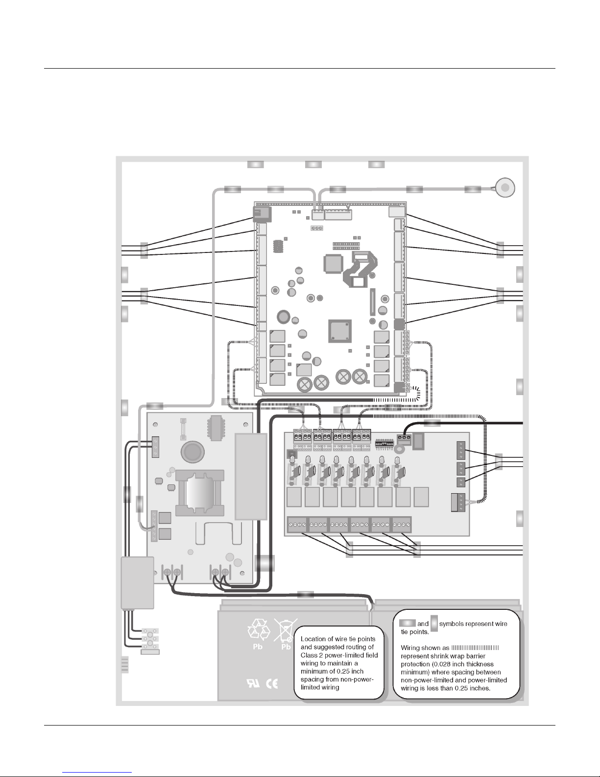
The following figure shows the NX4L1 panel components.
Figure 1: NX4L1 Panel Components
Enclosure Tamper Switch
NetAXS Access
Control Panel
Mounting
Screw
24VDC
Powe r
Supply
(cover not
shown)
3.5A
250V
Fuse
Powe r
Inlet
Terminal
Block
Cables
with heat
shrink
barriers
Mounting
Screws
Pb
Cables
with heat shrink
barriers
HPACM8
Power Distribution Board
Pb
3 A, 250V
Bussman type
GMA fuse
6 www.honeywell.com

Note: Maintain at least a .25-inch distance between the non-power limited wiring (115
VAC/60 Hz input wiring, power line filter wiring, 24 VDC wiring, battery
backup/charger wiring, and battery-to-battery wiring) and all other wiring, which is
power-limited Class 2 wiring.
3.1 NetAXS™ Access Control Unit
The NetAXS™ panel is a four-reader board that controls up to four doors by
providing up to 14 inputs and 8 outputs. The NetAXS panel may be used as a
stand-alone panel with independent card and transaction storage or, with a host
software upgrade, as a fully monitored online access control device. The NetAXS
panel also supports up to 30 downstream panels in a variety of network
configurations. See Communications, page 21, for descriptions and illustrations.
Fourteen inputs are capable of four state supervision: Normal, Alarm, Short and Open.
Eight inputs are used as door control with one input used for request to exit on each
door and one input used for door status on each door. Supervised inputs for Tamper,
External Power Fail and four Reader Tampers are supplied as well, and they can be
used as additional inputs when not required for their default purpose.
NetAXS™ NX4L1 Installation
Panel Components and Descriptions
Caution: The NetAXS board must not be used to power locks. Only through the relay
board can the common power supply be used for the NetAXS™ and locking devices.
Real-Time Clock Protection
The panel RTC is backed up using a super capacitor. The super capacitor will power
the real-time clock for one week in the absence of primary power or backup battery.
Memory Protection
The NetAXS™ panel continuously saves database and event information in
non-volatile FLASH memory. This activity prevents the panel from losing data when
power is lost.
Reader and AUX Power
Reader and AUX power is supplied at 12.4 VDC nominal with a maximum current
distribution of
600 mA. The current can be distributed throughout the Reader Power or AUX Power
in any configuration as long as the maximum draw is less than 600 mA: Reader 1 +
Reader 2 + Reader 3 + Reader 4 + AUX Power < 600 mA.
Caution: AUX Power must not be used to power locks.
For NetAXS™ maximum current draw refer to panel specifications.
NetAXS Access Control Unit NX4L1 Installation Guide, Document 7-901099, Revision A 7

NetAXS™ NX4L1 Installation
Panel Components and Descriptions
3.2 Power Supply
The NX4L1 uses an internal 115 VAC to 24 VDC regulated power supply (Altronix
Model AL600ULXB). The supply uses 115 VAC, 60 Hz, 2 Amp input, and provides
24 VDC at 6 Amps for the system power. The supply also charges and monitors the
condition of the batteries. Wire the unswitched electrical power to the supply per the
National Electrical Code as well as any local electrical codes, including the safety
ground wire.
An input power indicator is supplied, and it is illuminated when input voltage is
present. If the indicator is off, the input voltage is of f, or too low to operate the system.
Caution: De-energize the unit before servicing it. For continued protection against the
risk of electric shock and fire hazard, replace the input fuse with the rating of 3.5A,
250V.
3.3 Batteries
For the NX4L1, two CASIL CA1270, 12 VDC, 7 AHr sealed lead-acud batteries
(Honeywell order number 3-000066) wired in series must be used to have backup
battery capabilitiy. The batteries will provide standby backup power, depending upon
system configuration and activity. The batteries are wired in series (positive on one
battery to negative on the other) and connected to the BATT + and BATT - terminals
on the 24 VDC power supply in the NetAXS™ enclosure. When AC is lost, the power
supply automatically switches to the backup batteries for continuous 24 VDC power.
The power supply has deep discharge protection, and it can provide a Low Battery
signal to the panel if it is connected to a supervised input on the NetAXS™ panel.
Refer to the system wiring diagram for details. Replace the batteries every 2 to 2.5
years, or more often if the system has a high rate of backup use.
3.4 Enclosure
The enclosure is 450 mm (17.7 inches) wide, 607 mm (23.9 inches) high, 90 mm (3.54
inches) deep. The enclosure is shipped pre-wired.
3.5 Suppressors
Two suppressors (HAS number S-4) are required for each door lock. One suppressor
is installed on the panel control board, and the second must be installed at the door
lock.
8 www.honeywell.com
4.0 Installation
Perform the following steps to install the NX4L1 panel:
Warning: Use a static strap whenever touching the panel to ensure protection from
Electrostatic Discharge (ESD).
1. Review the panel layout, cable runs, and power needs.
2. Mount the enclosure at the proper location on the wall. Use appropriate
anchors for the mounting material.
3. Run all I/O wires to the enclosure, and properly mark each wire for its use.
4. Run appropriate length three-wire cable to the enclosure power inlet terminal
block. Ensure that the ground wire is properly grounded to earth. Note that an
Optional Power Connection kit (HAS part number 100-00049) is available for
the NX4L1 panel. To install the Power Connection option, see “Installing the
Optional AC Inlet“ on page 10 for instructions. The power inlet terminal block
can accommodate wire sizes up to 12 AWG. Wiring to a 20-amp branch circuit
requires 12 AWG insulated copper wire. Wiring to a 15-amp branch circuit
requires 14 AWG insulated copper wire. Connect the line, neutral, and earth
ground wires to the appropriate terminal on the power inlet terminal block.
NetAXS™ NX4L1 Installation
Installation
Caution: Do not apply power at this time.
5. Remove each terminal plug one at a time to wire the properly labeled cables.
See the wiring diagram (Figure 35 on page 52). Leave enough shield drain
length to secure to the grounding stud. Also, maintain a distance of at least .25
inches between the non-power limited wiring (115 VAC/60 Hz input wiring,
power line filter wiring, 24 VDC wiring, battery backup/charger wiring, and
battery-to-battery wiring) and all other wiring, which is power-limited Class 2
wiring.
Caution: Do not apply power at this time.
6. Connect the shield to the grounding studs.
7. Set DIP switch settings for the panel address (see Table 5 on page 27), and set
J36 and J37 for communication termination and biasing (see “System
Configuration“ on page 31 and “Jumper Settings“ on page 28).
8. Check all wiring at this time.
Caution: Improper wiring can cause damage to the NetAXS™ at power up and
result in a loss of warranty.
9. Apply power to the panel. The power-up sequence may take up to two minutes,
after which the RUN LED blinks green. The RUN LED is located near
Terminal Block (TB) 8. After the power-up sequence, check the LEDs to be
sure the panel has powered up properly (see “LED Operation“ on page 47).
10.Configure the panel by following the instructions in the NetAXS™ Access
Control Unit User’s Guide.
NetAXS Access Control Unit NX4L1 Installation Guide, Document 7-901099, Revision A 9

NetAXS™ NX4L1 Installation
Installation
11.If you are using a battery backup function, place the two 7 A-Hr batteries in the
enclosure with the battery terminals of each battery close to each other.
12. Attach the 4-inch Battery-to-Battery cable from the positive (red) terminal of
one battery to the negative (black) terminal of the other battery. DO NOT
CONNECT THE CABLE BETWEEN THE TERMINALS OF THE SAME
BATTERY.
13. Attach the positive (red) Power Supply-to-Battery cable to the remaining
positive (red) battery terminal.
14. Attach the negative (black) Power Supply-to-Battery cable to the remaining
negative (black) battery terminal.
15.For panels using the Ethernet connection, the cable clamp (HAS part number
3-000342) must be used for the panel to pass the FCC Part 15 Class B
requirements. Snap the clamp around any portion of the Ethernet cable that is
inside of the enclosure.
4.1 Installing the Optional AC Inlet
Perform these steps to install the optional AC inlet (HAS part number 100-00049):
1. Remove the knockout piece at the lower-left side of the enclosure.
2. Feed the AC inlet assembly wires through the opening from the outside.
3. Push the receptacle straight in, until it snaps into place.
4. Connect each colored wire to its corresponding color on the terminal block.
5. Plug the AC inlet unit’s power cord into the three-prong receptacle.
6. Plug the other end of the cable into a standard non-switched 115 VAC outlet.
Note: Use only a Yung Li YC-12 power cord (HAS part number 700-0109). UL has
evaluated the use of this power cord with the optional AC inlet for the NX4L1. You
can purchase this power cord from Honeywell.
10 www.honeywell.com
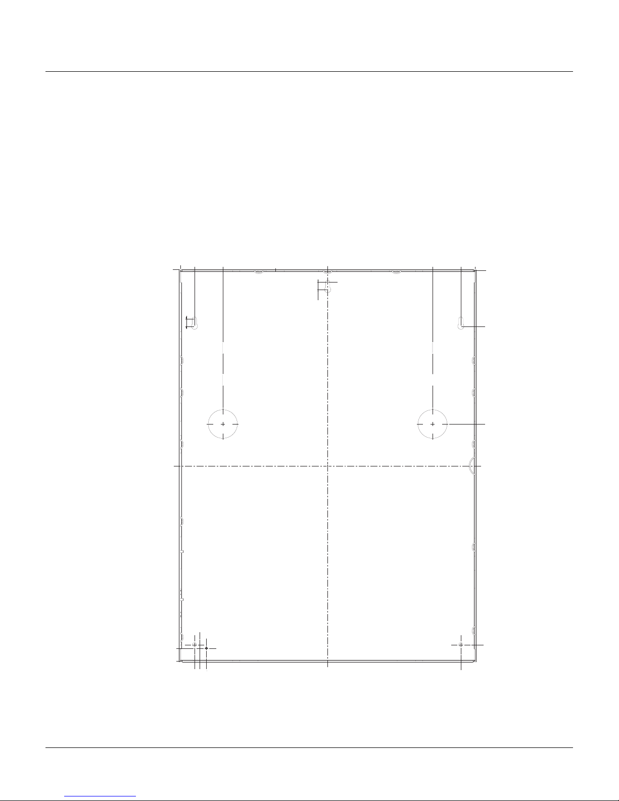
4.2 Tying the Field Wiring in the NX4L1 Cabinet
Use the following figure as a guide to secure the field wiring in the NX4L1 cabinet.
Figure 2: Tyin g the Field Wiring in the NX4L1 Cabinet
NetAXS™ NX4L1 Installation
Installation
NetAXS Access Control Unit NX4L1 Installation Guide, Document 7-901099, Revision A 11
Pb
Location of wire tie points
and suggested routing of
Pb
Class 2 power-limited field
wiring to maintain a
minimum of 0.25 inch
spacing from non-power-
limited wiring
.
Wiring shown as ||||||||||||||||||||||||||||
represent shrink wrap barrier
protection (0.028 inch thickness
minimum) where spacing between
non-power-limited and power-limited
wiring is less than 0.25 inches.
NetAXS™ NX4L1 Installation
Installation
4.3 Cabinet Mounting
The following five figures show the back, top, bottom, right, and left views of the NetAXS™ panel
cabinet. Each view includes the dimensions and knockout placement that you will need to mount the
cabinet. See Table 1 on page 16 for dimensions of the conduit entries into the cabinet.NetAXS™ Panel
Cabinet, Back View
Figure 3: NetAXS™ Panel Cabinet, Back View
17 23/32" (450 mm)
0
16 27/32" (428.2 mm)
15 5/32" (385 mm)
15/32" (11.51 mm)
8 27/32" (225 mm)
23/32" (18 mm)
2 9/16" (65 mm)
27/32" (21.8 mm)
0
0
15/32" (11.51 mm)
3 13/32"
(86.51 mm)
9 3/8"
(238.50 mm)
23 1/8" (587 mm)
23 29/32" (607 mm)
16 27/32" (428.2 mm)
16 17/32" (420 mm)
16 5/32" (410 mm)
12 www.honeywell.com
27/32" (21.8 mm)
22 29/32"
(581.6 mm)
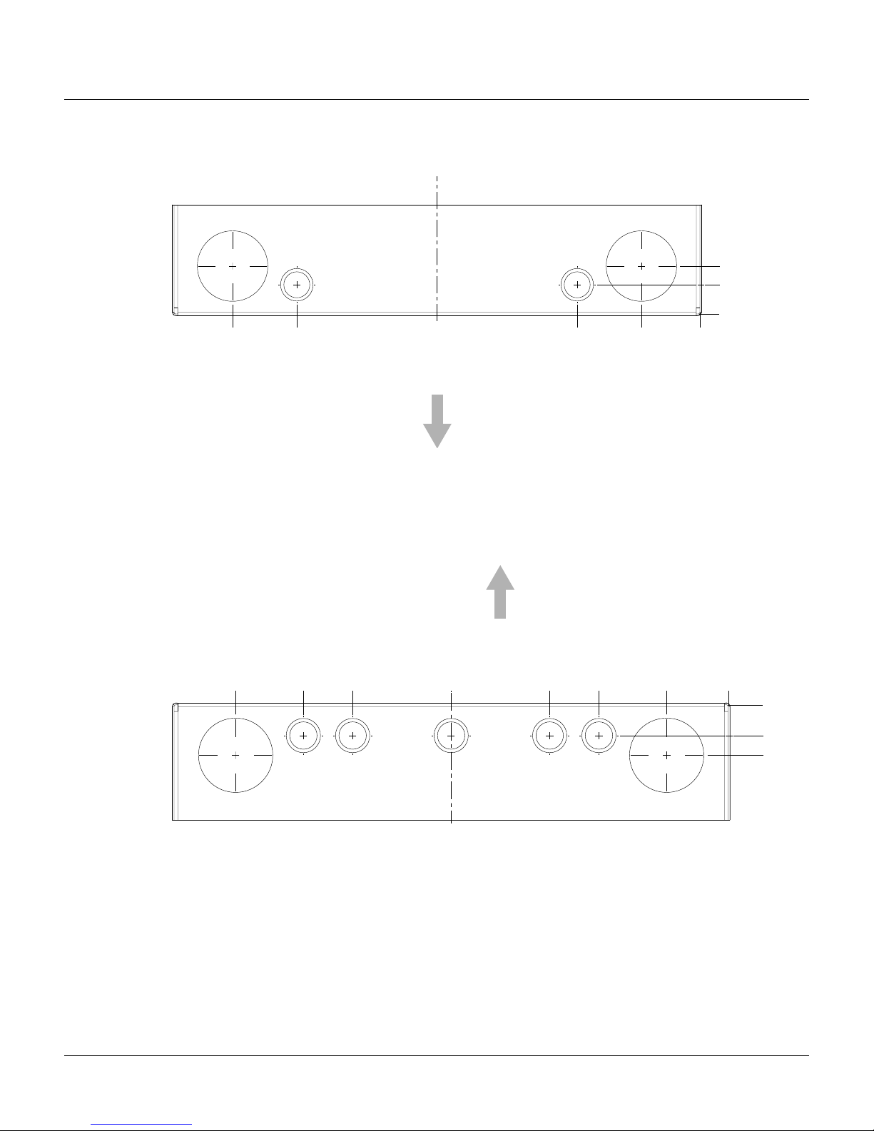
Figure 4: NetAXS™ Panel Cabinet, Top View
0
0
31/32" (25 mm)
1 5/8" (41 mm)
1 31/32" (50 mm)
4 1/8" (105 mm)
5 23/32" (145 mm)
8 27/32" (225 mm)
15 3/4"" (400mm)
13 19/32" (345 mm)
12" (305 mm)
Back
15 3/4" (400 mm)
13 19/32" (345 mm)
Back
4 1/8" (105 mm)
NetAXS™ NX4L1 Installation
Installation
1 5/8" (41 mm)
31/32" (25 mm)
0
1 31/32" (50 mm)
0
Figure 5: NetAXS™ Panel Cabinet, Bottom View
NetAXS Access Control Unit NX4L1 Installation Guide, Document 7-901099, Revision A 13
NetAXS™ NX4L1 Installation
Installation
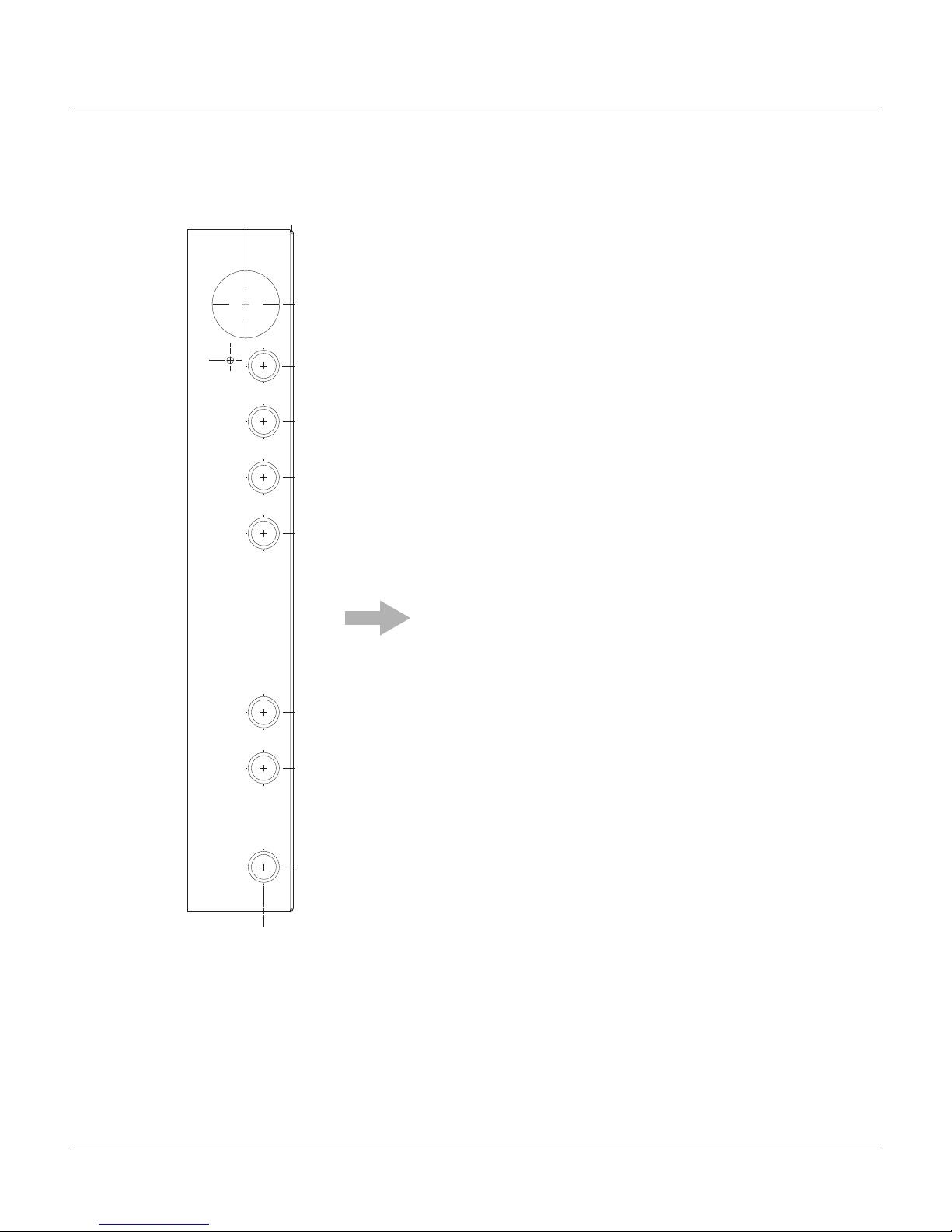
Figure 6: NetAXS™ Panel Cabinet, Left View
(41 mm)
1 5/8"
4 17/32" (115 mm)
2 5/32" (55 mm)
0
0
2 9/16" (65 mm)
4 23/32" (120 mm)
6 11/16" (170 mm)
8 21/32" (220 mm)
(25 mm)
10 10/16" (270 mm)
Back
16 30/32" (430 mm)
18 29/32" (480 mm)
22 3/8" (568.5 mm)
31/32"
14 www.honeywell.com
 Loading...