

Honeywell NX Pocket Programming Manual

NX Series Inverters
HVAC Pocket Programming Guide
Проектирование. Монтаж. Продажа. - http://vskd.ru

HVAC Pocket Programming Guide
This guide provides a single reference document for the user of NXL HVAC (product codes
starting with HVAC) and NXS (product codes starting with NXS) inverters, when using
Basic Speed Control and PID Control in HVAC applications.
Contents
Introduction 03
NXL HVAC Inverter Connections 04
Information on control connections of NXL HVAC inverters
NXS Inverter Connections 05
Information on control connections of NXS inverters
Operating the NXL HVAC Keypad 06
Information and tips on operating the keypad
NXL HVAC Basic Speed Control 08
Commissioning and operation in Basic Speed Control
NXL HVAC PID Control 10
Commissioning and operation in PID Control
Operating the NXS Keypad 12
Information and tips on operating the keypad
NXS Basic Speed Control 14
Commissioning and operation in Basic Speed Control
NXS PID Control 16
Commissioning and operation in PID Control
Inverter Fault Tracing 18
Fault codes, possible causes and correcting measures for both product series
HVAC Pocket Pro
g
rammin
g
Guide / Contents
02
Проектирование. Монтаж. Продажа. - http://vskd.ru

Introduction
Basic Speed Control
PID Control
Variable Frequency Drive
Control System
Motor
Fan
or
Pump
Load
Pressure
Sensor
Setpoint Signal
V signal to AI1
mA signal to AI2
V signal to AI1
mA signal to AI2
Pump
Fan
or
Load
Pressure
Sensor
Control System Variable Frequency Drive
Motor
Speed Signal
V signal to AI1
mA signal to AI2
Introduction
03
Проектирование. Монтаж. Продажа. - http://vskd.ru
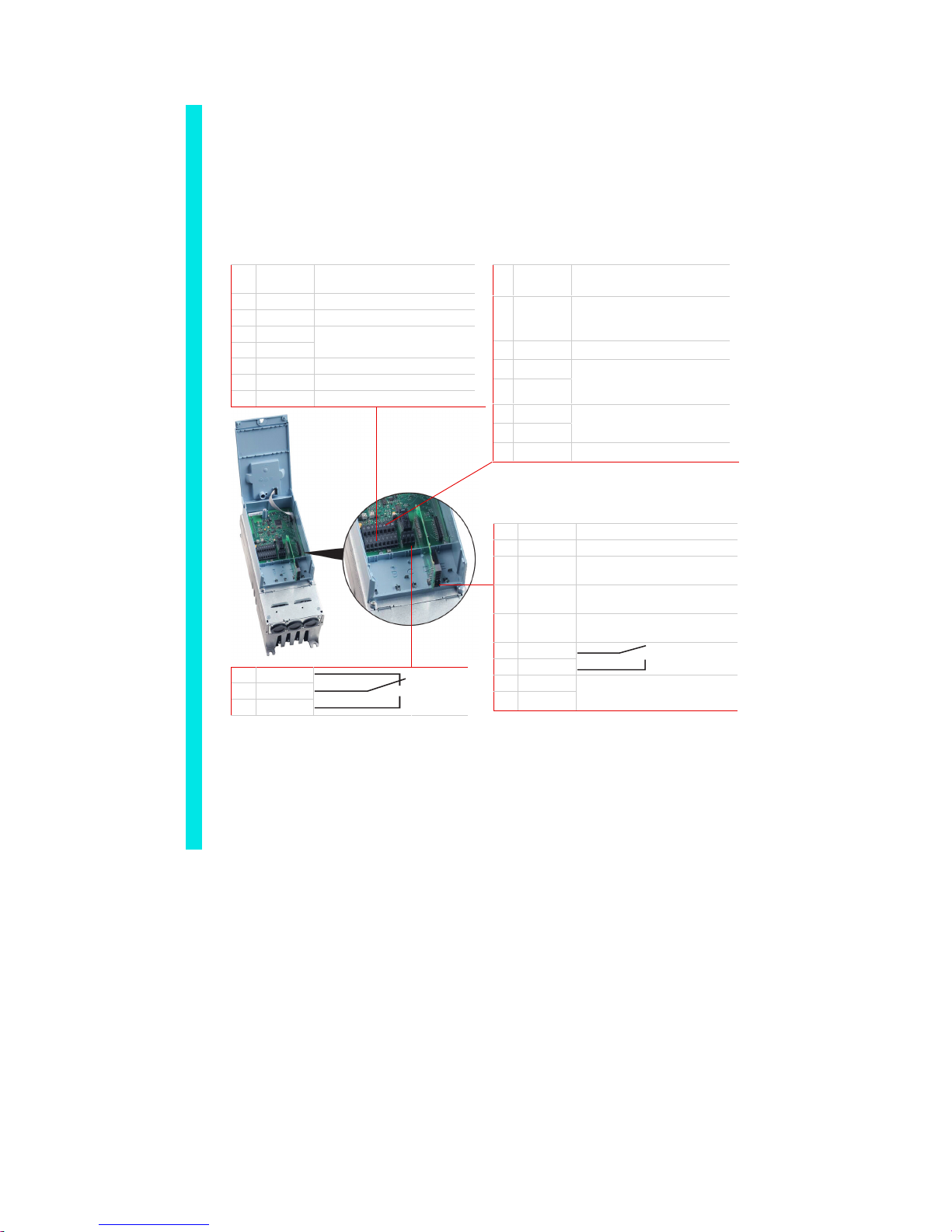
NXL HVAC Inverter Connections
Installation and Power Connections
See the NXL HVAC Quick Guide and NXL HVAC Safety Guide (attached to each drive)
for information on installation, cabling, cooling, power connections and safety. More
information can be found in the NXL HVAC User’s Manual, which can be downloaded from
http://www.inettrack.europe.honeywell.com/support.
Control Terminal Connections
1 + 10 V
ref
Reference output
(voltage for potentiometer etc.)
2 AI1 + Analogue Input 1 (V signal)
3 AI1 – I/O Ground
4 AI2 +
5 AI2 –
Analogue Input 2 (mA signal)
6 +24 V +24 V output (max. 0.1 A)
7 GND I/O ground
8 DIN1 Digital Input 1 (Start forward)
9 DIN2 Digital Input 2
(Start reverse)
10 DIN3 Digital Input 3
(Preset speed 1,
default: 10 Hz)
11 GND I/O Ground
18 AO1 +
19 AO1 –
Analogue output 1
Range 0–20 mA/RL,
max. 500
Ω
A RS485
B RS485
Modbus RTU, serial bus
30 +24V Input for +24 V backup voltage
12 + 24 V +24 V output (max. 150 mA)
13 GND I/O ground
14 DIE1 Exp. Digital Input 1 (Preset
speed 2, default: 50 Hz)
15 DIE2 Exp. Digital Input 2
(Fault Reset)
16 DIE3 Exp. Digital Input 3
(Disable PID)
25 ROE1
26 ROE1
Exp. Relay 1
NO (run)
28 TI+
29 TI –
Thermistor Input;
Rtrip = 4.7 k1Ω (PTC)
21 RO1
22 RO1
23 RO1
Relay 1
NO/NC
(fault)
NXL HVAC Inverter Connections
04
Проектирование. Монтаж. Продажа. - http://vskd.ru
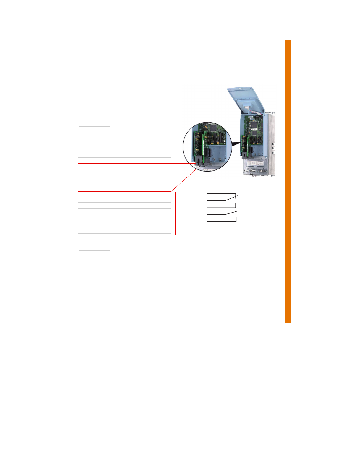
NXS Inverter Connections
Installation and Power Connections
See the NX Series User’s Manual (included with every shipment) for information on
installation, cooling, power connections and safety. The manual can also be downloaded
from http://www.inettrack.europe.honeywell.com/support.
Control Terminal Connections
1 +10 V
ref
Reference output (voltage for
potentiometer etc.)
2 AI1 + Analogue Input 1 (V signal)
3 AI1 – I/O ground
4 AI2 +
5 AI2 –
Analogue Input 2 (mA signal)
6 +24 V +24 V input/output (max. 0.1 A)
7 GND I/O ground
8 DIN1 Digital Input 1
9 DIN2 Digital Input 2
10 DIN3 Digital Input 3
11 CMA Digital input common for DIN1,
DIN2 and DIN3
12 +24 V Same as terminal 6
13 GND I/O ground
14 DIN4 Digital Input 4
15 DIN5 Digital Input 5
16 DIN6 Digital Input 6
17 CMB Digital input common for DIN4,
DIN5 and DIN6
18 AO1 +
19 AO1 –
Analogue output 1, default
range: 0–20 mA/RL, max.
500 Ω
20 DO1 Open collector Output
21 RO1
22 RO1
23 RO1
Relay 1
NO/NC
25 RO2
26 RO2
Relay 2
NO
28 TI+
29 TI-
Thermistor Input;
Rtrip = 4.7 kΩ (PTC)
NXS Inverter Connections
05
Проектирование. Монтаж. Продажа. - http://vskd.ru

Operating the NXL HVAC Keypad
Reading the Display
Keypad Push-Buttons
RUN and STOP
Indicate if the drive is
running. When RUN
blinks, STOP command
has been given but the
motor is still rotating.
A
LARM
Lights up to warn that the drive is running outside
a certain limit.
FAULT
Indicates that unsafe operating conditions caused
the drive to stop.
CONTROL PLACE
A
ctive control place is visible: keypad, I/O or
fieldbus.
NUMERIC INDICATIONS
Provide information on values and location in the
menu structure.
UNIT
Unit of the value on screen visible.
READY
Lights up when AC power is on. In case of a fault,
the symbol will not light up.
DIRECTION
Active motor
direction visible:
forward or
reverse.
ENTER
- Confirmation of selections
- Fault history reset (2 – 3 s)
RESET
Reset active faults
Note: The motor may start immediately after
resetting the fault!
RIGHT
- In menu: move forward
- In parameter edit mode: move cursor right
- Enter edit mode
START and STOP
Control the motor if the keypad is the active control
Tip: Hold STOP down 5 s to launch the
START UP WIZARD
LEFT
- In menu: move backward
- In parameter edit mode: move cursor left
- Exit edit mode
Tip: Hold LEFT down 3 – 5 s for
control place change
KEYPAD REMOTE
UP+ and DOWN
–
- Browse the pages in main and submenus
- Edit values
O
p
eratin
g
the NXL HVAC Ke
yp
ad
06
Проектирование. Монтаж. Продажа. - http://vskd.ru
 Loading...