

Page 1
Page 2
Page 3
GENERAL
DESCRIPTION
The MO953 and MP953 Pneumatic
(“Actuators”) are used with
and
Actuators
Valves and
can control older steam and water valves via adapters. The
Actuators are functionally identical to the
Actuators. Therefore, most of this sheet is
directed to the MP953 Actuators.
and B Actuators use a Gradutrol Relay for
positioning, and the
and
Actuators use a
positive positioner. The relay and the positioner function in
essentially the same way. Positivepositionerretrofitkitsare
available for
and B Actuators (see
ACCESSORIES).
APPLICATION
These Actuators operate the
and certain other coil, line, and zone valves that
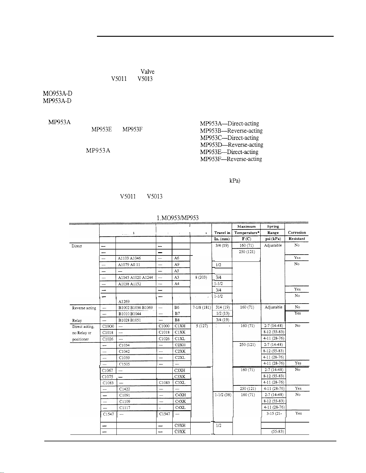
Device Type Active Inactive Active Inactive In. (mm)
acting
with Gradutrol
Relay
and
Table
MP953
A1087 A1004 A1210
Al095 A1012 Al228
All78 A1053
A1202 All86 A1061
Valves
I
MO953
Al 5 (127)
A2
A7
A8
I
proportionally control steam or hot and cold liquids in
HVAC systems.
SPECIFICATIONS
MODELS:
MAXIMUM SAFE AIR PRESSURE
25 psi (172
See Table 1 for additional specifications.
Specifications.
Size in
(13) 160 (71)
314 (19)
(19)
(38)
(19)
13 (330)
(38)
with Gradutrol
314 (19)
I
Cl141
Cl158
Cl067 C3XH
Cl075
1
8 (203)
5 (127)
(13)
103)
2-7 (14-48) No
8-l 2 (55-83)
3-91 75-5500
Page 4
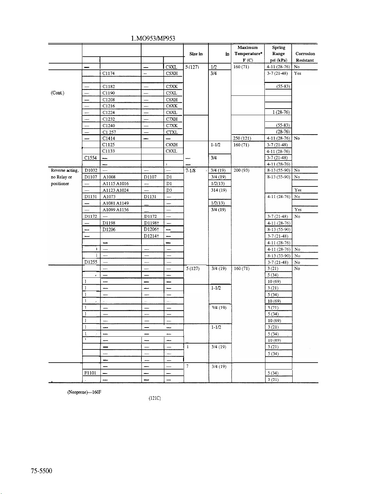
Table
Specifications (Continued).
Device Type
Direct acting
no Relay or
positioner
MP953
Active
Cl471 Cl125
Cl489 Cl133 Cl489
Cl562
D1222
D1230
D1248
Inactive
Cl166
D1214
Active
Cl471
D1222
MO953
Inactive In (mm)
Cl554
Cl562
8 (203)
13 (330)
(181)
Travel
In (mm)
(13)
(19)
(38)
(19)
8-12
4-l 1 (28-76)
250
(121) 3-7 (21-48)
8-12 (55-83)
4-l
160
(71) 3-7 (21-48)
8-12
4-l 1
Direct acting
with positive
positioner
Reverse acting
with positive
wsitioner
*Diaphragm color indicates maximum temperature:
Black
Black with White Dot (Ethylene Propylene-250F
El301
El319
El327
El277
El285
El293
El368
El376
El384
El400
El418
El427
El435
El443
F1119
F1093
(71C)
8 (203)
13 (330)
3 (330)
(180)
(38)
(38)El392
160 (71)
10 (69)
10 (69)
,
No
Page 5
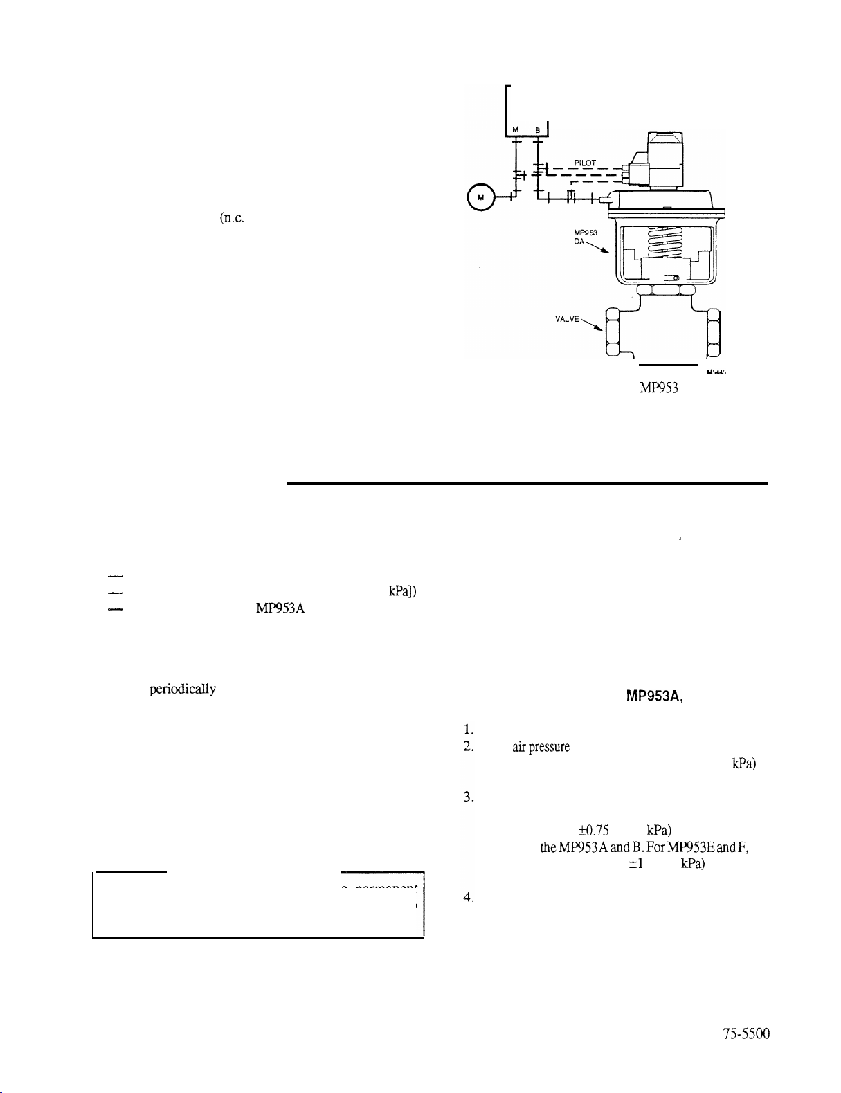
OPERATION
In a direct-acting (n.o. valve) system, an increase in
control (branch/pilot) air pressure forces the Actuator
diaphragm and cup assembly downward, forcing the valve
stem down to proportionally close off the flow through the
valve (Fig. 1).
1
THERMOSTAT
POSITIONER
In a reverse-acting
control (branch/pilot) air pressure forces the Actuator
diaphragm and cup assembly upwards, forcing the valve
stem up to proportionally increase the flow through the
valve.
In Actuators without Gradutrol Relays or positive
positioners, branchline pressure is applied to the
diaphragm. In Actuators with Gradutrol Relays or positive
positioners, up to full main air pressure is applied to the
diaphragm to ensure the valve is positioned proportionally
to the pilot pressure (the branchline pressure output from
the controlling device).
valve) system, an increase in
MAINTENANCE
EQUIPMENT NEEDED
Commercial cleaning solvent or degreaser
Pressure Gage 14003519 (0 to 30 psi [0 to 207
Wrench 301572A for
and B
Fig. 1. Typical Direct-Acting
Operation.
OPERATIONAL CHECK
Vary the branchline (pilot) pressure through the
operational range of the Actuator in both directions. The
valve should open and close smoothly.
VISUAL INSPECTION
Check
visible problems.
for leaks, loose fittings, and other
CLEANING
Clean the Actuator with a commercial cleaning solvent or
degreaser.
A
WARNING
Careless handling of solvents can cause permanent
respiratory or skin damage. Avoid prolonged exposure to
solvents.
A
ADJUSTMENTS
CHECK ADJUSTMENT ON
Install gages in the main and pilot air lines.
Main
top of the sequencing range (span): 13 psi (90
the minimum main pressure for the device to function.
Slowly increase
which the valve stem begins to travel. This pressure
should be within
setting
pressure should be within
point.
Continue increasing the pilot pressure until the valve
stem stops traveling. This pressure should be the start
point pressure plus the range (span) setting.
of
should be greater than or equal to the
pilot
pressure and note
psi (5
B, E, F
the
of the start point
psi (7
pressure at
of the start
is
Page 6
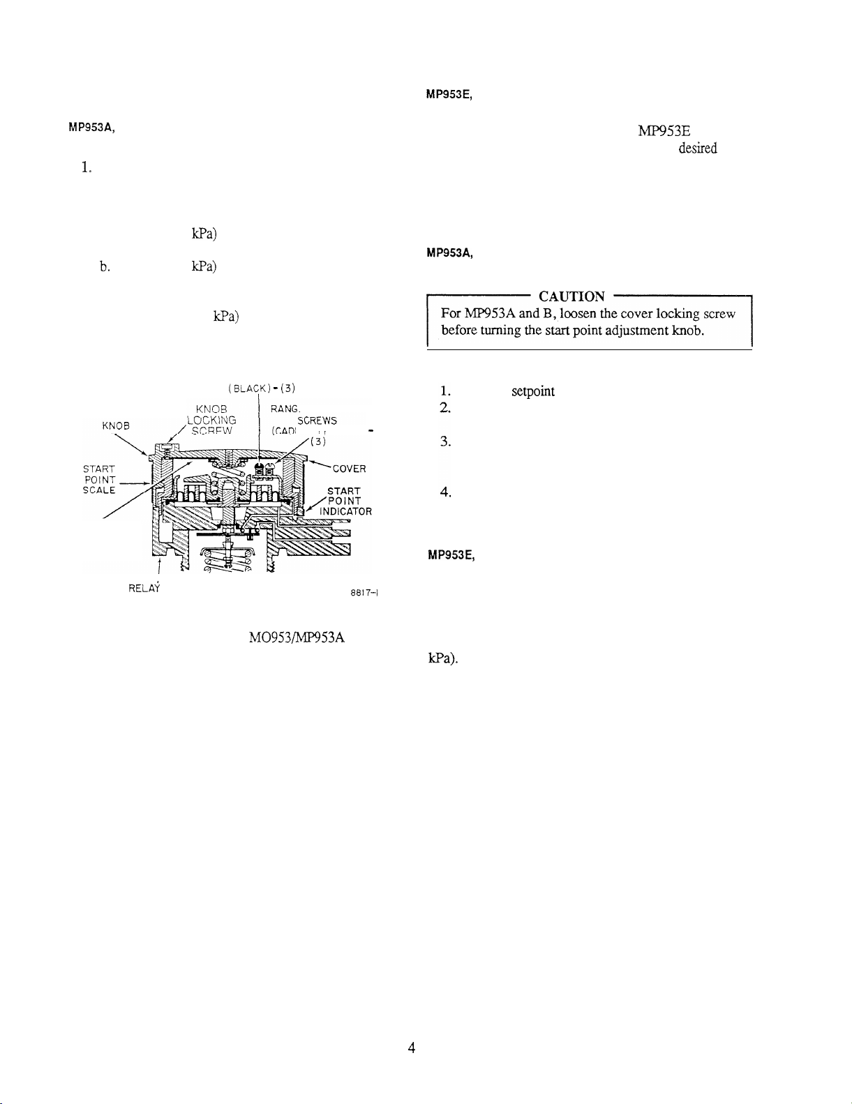
SET OPERATING RANGE
F
B
Use Wrench 301572A to loosen the cover locking
screw (Fig. 2).
Unscrew the start point adjustment knob until thread
2.
is disengaged. Remove knob.
a.
For 3 psi (21
range, back all range adjustment
screws off to friction stop.
For 5 psi (34
range, back only the black range
adjustment screws to stop and tighten the outer,
cadmium-plated range adjustment screws.
c. For 10 psi (69
range, tighten all range
adjustment screws.
START POINT
ADJUSTMENT
RANGE
ADJUSTMENT
INSTRUCTIONS
SHOWN HERE
RANGE ADJUSTMENT SCREWS
E ADJUSTMENT
M IUM
PLATED)
Change the operating range of
and F by
replacing the feedback spring with one for the
(see REPAIR).
ADJUST START POINT
Reinstall
knob.
Tighten knob by turning it until it is seated on relay
body (Fig.
2).
Loosen knob (maximum of one turn) until start point
of correct scale range lines up with start point
indicator.
Tighten knob locking screw until it engages relay
body. Do not overtighten.
range
Fig. 2. Adjustment Points of
Gradutrol Relay.
and B
Set the start point on the positioner to the value shown on
the job drawings. Critical applications and feedback spring
changes mightrequire fine-tuning the
of the start point knob will adjust the start
start
point. Each click
point
0.25 psi (1.7
75-5500
Page 7
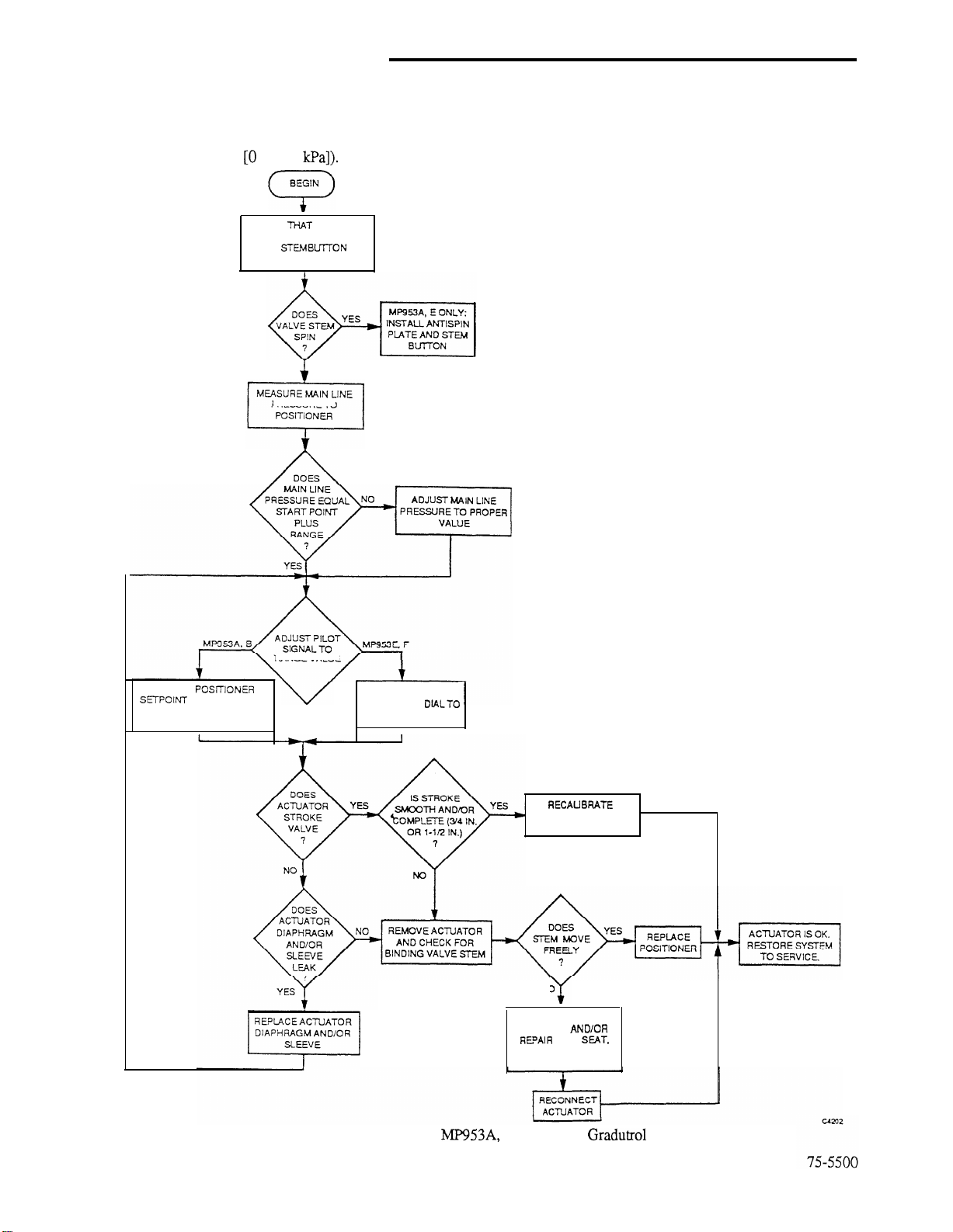
TROUBLESHOOTING
EQUIPMENT NEEDED
Troubleshooting procedures require Pressure Gage
14003519 (0 to 30 psi
to 207
CHECK
IS SECURELY MOUNTED
AND
PROPERLY LATCHED
ACTUATOR
NO
PRESSURETO
DOES
SYMPTOMS AND CORRECTIVE
ACTION
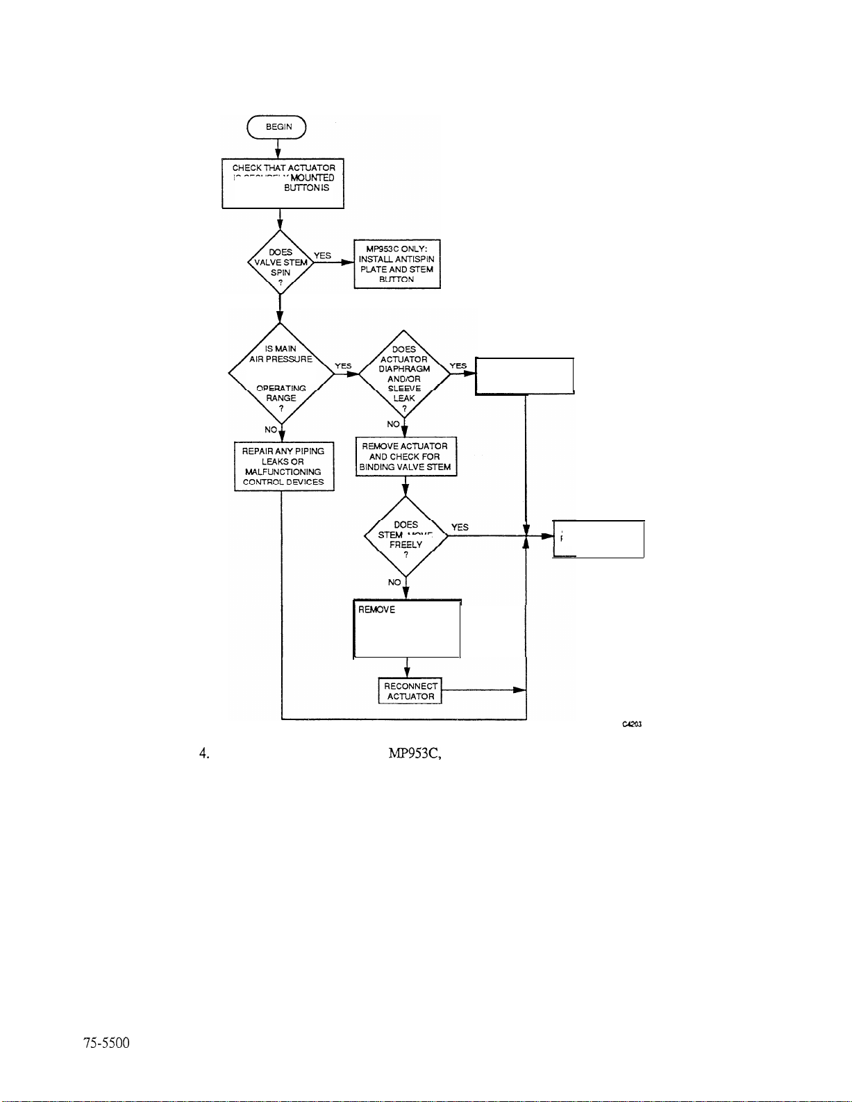
Figures 3 and 4 show troubleshooting flowcharts.
LOOSEN
TURN COVER SCALE TO
BELOWZERO START POINT.
RANGE VALUE
ADJUST POSITIONER
START POINT
MINIMUM VALUE
I
POSITIONER START
POINT IF NECESSARY
NO
REMOVE ANY FOREIGN
MATERIAL;
DISC, SEAT.
AND STEM; AND/OR
REPACK VALVE
Fig. 3. Troubleshooting Flowchart for
B, E, F (with
5
Relay/Positioner).
Page 8
IS SECURELY h4OUNTED
AND STEM
PROPERLY LATCHED
NO
ADEQUATE FOR
COMPLETE
Fig.
Troubleshooting Flowchart for
MATERIAL; AND/OR
REPAIR DISC, SEAT,
AND STEM; AND/OR
REPACK VALVE
REPLACE ACTUATOR
DIAPHRAGM AND/OR
SLEEVE
ACTUATOR IS OK.
RESTORE SYSTEM
TO SERVICE.
D (without Gradutrol Relay/Positioner).
Page 9

REPAIR
GENERAL
This section lists tools needed to disassemble and
reassemble Actuators and gives procedures for replacing
parts of actuators. See PARTS AND ACCESSORIES for
parts diagrams and lists.
EQUIPMENT NEEDED
Tables 2 through 5 list basic repair tasks and the tools
required for each.
Table 4. Loosening and Removing Actuator Bases from
Valve Bonnets.
Device
Model
Series Dia (In.)
Actuator
Tools Required
wrench (bit)
or T-25 Torx bit
NOTE:Used only
1989
or later date
Table 2. Removing and Replacing Actuator Covers.
Model
hex socket
hex socket
Two l/4-20 x 3 in. hex-head
bolts, threaded to within
of bolt head
hex socket
-Four
bolts, threaded to within
x 3 in. hex-head
of bolt head
hex socket
All
5
8
13
7
Table 3. Removing and Replacing Actuator Bases.
De vice
Model
2
1
Series Dia (In.)
Actuator
5
Tools Required
hex socket
hex socket or T-25
Torx bit
NOTE: Series number does not
indicate type of
fastener.
six-point, deep socket
drive preferable)
wrench (bit)
wrench (bit)
wrench (bit)
or T-25 Torx bit
NOTE: Series number does not
indicate type of
fastener.
Table 5. Miscellaneous Tasks.
Task
Removing
Gradutrol Relay positioner
Removing
positioner
Removing
Gradutrol Relay positioner
bracket assembly
Removing
positioner bracket assembly
Removing and replacing
D, F sleeve
diaphragm
Replacing feedback-spring
cup on
diaphragm
Unlatching actuator from
valve stem button
Lubricating
Gradutrol Relay positioner
O-ring
Lubricating
positive positionerO-ring
positive
positive
E main
actuatorsregardlessof date
umber does not
Tools Required
Crescent wrench with jaw
opening to at least
mm). Narrow-jaw pipe wrench or
large adjustable pliers may be
substituted as long as they do not
the setpoint knob.
distort
Adjustable crescent wrench with
jaw opening to at least
(67 mm).
Small-blade screwdriver
hex socket
l-3/8-in. adjustable hex socket
(crescent wrench is acceptable
substitute)
Pliobond glue or equivalent
Medium- to large-blade
screwdriver
Lubricant or silicone grease
obtained locally
in. (67
in.
75-5500
Page 10

GRA
DUTRO
ASSEMBLIES
313695 J
CUP
SCREW
NUT OS0 X
5/16 ROUND
IN.
THICK
6-32 X
SPRING
ROUND H
31371
A
PARTS BELOW COMMON TO AU RELAYS
CUP ASSY
START
SPRING
Fig. 5.
PARTS BELOW COMMON TO ALL RELAYS
VALVE UNIT
1
THE 313711A AND D MODELS HAVE
DUAL BARBED CONNECTORS; THE
3137118 AND C MODELS USE
THREAD CONNECTION. THE
AND
MODELS HAVE DUAL SCALE,
ENGLISH AND METRIC; THE 313711C
AND D MODELS HAVE ENGLISH
Relay Assemblies Exploded View.
-
Page 11

MO953
JO CONVFRT A4
IN. (203 MM)
RELAY ASSY 313695J
FEEDBACK SPRING
3 13696-00063
CUP 315178-00062
DIAPHRAGM 311750 OR
314153
CUP
CONVERSION
YOKE ASSEMBLY
-SCREW
PLATE
13 IN. (330 MM)
RELAY ASSY
FEEDBACK SPRING
CUP 315178-00062
DIAPHRAGM 312505
CUP 315020-00124
-DIAPHRAGM
Fig. 6. MO953 Conversion.
Black with white spot: Ethylene Propylene
Maximum temperature 250F (121C)
Used on
D and F
White: Silicone
Maximum temperature 250F (12
Used on
and C and may be installed on
Flat diaphragms and beaded-roll diaphragms are not
interchangeable. Neoprene and EPR diaphragms are
interchangeable but must meet maximum temperature
requirements.
Direct-acting Actuators are subject to extremely high
internal spring loads. Therefore, Actuator covers must be
removed very carefully before the the main diaphragm can
be replaced.
When using the following procedures, see Figures 8 and
10 for exploded diagrams and Tables 6 and 8 for parts.
SPRING
314652
YOKE
314651 (314651A)
316059 (316059A)
ASSEMBLY
ASSEMBLY
NYLON INSERT
SUPPORT WITH
SUPPORT WITH
314653
Fig. 7. Yoke Assembly.
REPLACE MAIN DIAPHRAGM
GENERAL
Before replacing the diaphragm, determine the type and
material of the existing diaphragm according to its color:
Black: Neoprene
Maximum temperature 160F (71C)
Used on
and E
REMOVE ACTUATOR COVER
WARNING
A
A
Use extreme caution when disassembling Actuators.
Actuator assemblies are under spring load which can reach
Disconnect all air lines, including any connected to
Gradutrol Relay or positive positioner, if present.
2.
and E only: Remove Relay/positioner from
Actuator cover by turning counterclockwise.
Remove exposed feedback spring.
3.
See WARNING in this section. Loosen cover
4.
setscrews sequentially
Check whether cover can be squeezed back to
5.
turns each.
by hand. If so, continue sequentially loosening screws
until cover is free. Remove cover, diaphragm, and go
to REPLACE DIAPHRAGM.
If cover cannot be squeezed back to frame, use the
6.
following guides according to Actuator size.
NOTES:
a. Bolts should be threaded to within
approximately
b.
In each case, turn the long bolt in until its head
in. of their heads.
contacts the cover flange.
8-m Actuator: Remove two cover screws
that are directly opposite each other. Replace
cover screws with
x 3 in. bolts.
Page 12

13-in. Actuator: Sequentially remove and
replace every second cover screw with a
16-18 x 3 in. bolt.
7.
Continue sequentially loosening all bolts/screws until
all original (short) bolts/screws are disengaged.
Continue to loosen remaining long bolts alternately
until no more spring load exists. Remove bolts, cover,
and diaphragm.
REPLACE DIAPHRAGM
Fit new diaphragm over Actuator cup. Position cover
1.
over diaphragm,
2.
Reinstall Actuator cover following procedure in
REMOVE ACTUATOR COVER in reverse order.
NOTE: In some cases, cup and diaphragm will be
forced above top of frame. As cover is
tightened, check that diaphragm bead is
properly positioned in its retention groove.
3‘
spring cup to new diaphragm. Cup must be centered
in hole of Actuator cover.
4.
Reassemble feedback spring and Relay/positioner.
Make certain that each end of spring is located in a
spring cup (one end on diaphragm and the other end
in Relay/positioner) before screwing Relay/
positioner back into position.
Reinstall air lines and restore system to service.
Reverse-acting Actuators are not subject to high internal
spring loads. Therefore, the Actuator cover can be removed
routinely.
and E only: Cement positioner feedback
D, F REVERSE-ACTING ACTUATORS
Reinstall small sleeve cup, ring, and screws.
5.
6.
Install new main diaphragm, checking that it is
properly located.
Reinstall cup, lockwasher, and nut. Tighten nut
7.
enough to seal diaphragm against cup.
8.
Reinstall feedback spring. Check that spring is
securely seated in grooves on lever and cup support.
9.
Reinstall cover and cover screws.
Reinstall air lines and restore system to service,
10.
REPLACE ACTUATOR BASE
When using the following procedure, see Figures 8 and
10 for exploded diagrams and Tables 6 and 8 for parts.
WARNING
A
Use extreme caution when disassembling Actuators.
Actuator assemblies are under spring load which can reach
550 pounds.
1.
To eliminate internal forces in Actuator assembly and
remove Actuator cover, refer to REMOVE
ACTUATOR COVER under
DIRECT-ACTING ACTUATORS in REPLACE
DIAPHRAGM section.
2.
Remove Actuator cup, spring, retainer, plate,
mainspring, and ring
3.
Remove fasteners securing base to frame.
4
Install new base assembly and reinstall fasteners.
5.
Reassemble Actuator assembly by following
procedure in Steps 1 and 2 in reverse order.
6.
Reinstall air lines and restore system to service.
A
C, E
models only).
Replace diaphragm and sleeve (inner seal) together. Use
SERVICELINE Kit 14003
are rated at 250F
When using the following procedure, see Figures 9 and
11 for exploded diagrams and Tables 7 and 9 for parts.
Disconnect all air lines, including any connected to
Gradutrol Relay or positive positioner, if present.
Remove cover screws, cover (on
Relay/positioner remains attached to cover),
feedback spring
lockwasher, cup, and diaphragm.
Remove small sleeve cup, screws, ring, and sleeve
diaphragm.
Install new sleeve diaphragm, checking for proper
seating in its locating groove.
75-5500
for all Actuators. Parts
and F,
F), large nut,
10
D, F REVERSE-ACTING ACTUATORS
When using the following procedure, see Figures 9 and
for exploded diagrams and Tables 7 and 9 for parts.
WARNING
To safely disassemble and reassemble reverse-acting
Actuators with 8 psi start point, a mechanical advantage is
required due to the high compression of the main spring
(200 pounds). For safety, use a large bench vise or C-clamp
and two blocks of wood.
1.
To release support assembly from Actuator cup, refer
to Steps 1 through 3 in
ACTING ACTUATORS under REPLACE MAIN
DIAPHRAGM.
A
A
D, F
Page 13

2.
See WARNING in this section. Sequentially loosen
fasteners securing base to frame. Base pops
frame when fasteners disengage.
When tension is relieved, remove fasteners and base.
3.
Install new base assembly.
4.
Reinstall fasteners.
5.
Reassemble Actuator assembly by following
6.
procedure in Steps 1 and 2 in reverse order.
Reinstall air lines and restore system to service.
7.
REPLACE ACTUATOR MAIN
SPRING
Remove the main
by following the procedure in REMOVE ACTUATOR
COVER under
ACTUATORS in REPLACE MAIN DIAPHRAGM
section. This procedure relieves all internal spring force and
makes the spring fully accessible.
See PARTS for the proper replacement spring.
on direct-acting Actuators
safely
NOTE:
3. Remove feedback spring. Retain old spring for
4. Install original feedback spring in diaphragm cup
when Relay/positioner is being replaced with an
identical device.
5. When replacing Gradutrol Relay with a new-style
positive positioner, discard original spring and install
feedback spring with proper range from appropriate
retrofit kit. For part number, see POSITIONER
RETROFIT AND SPRING KITS in PARTS AND
ACCESSORIES.
6. Position new O-ring in groove of Relay/positioner
base and install new Relay/positioner in Actuator
cover.
NOTE: Compress feedback spring as the Relay/
Tighten Relay/positioner only enough to seat large
7.
Considerable force may be required before
the positioner begins to turn because of the
large O-ring that seals the Relay/positioner
to the Actuator cover.
positioner is screwed in place. Check that
both ends of the feedback spring are located
in the spring cups, one in the Relay/
positioner and one cemented to the Actuator
diaphragm.
Remove the main spring on reverse-acting Actuators
safely by following the procedure in
DIRECT-ACTING ACTUATORS in REPLACE MAIN
DIAPHRAGM section. This procedure relieves all internal
spring force and makes the spring fully accessible.
See PARTS for the proper replacement spring.
D, F
REPLACE GRADUTROL RELAY/
POSITIVE POSITIONER
When using the following procedure, see Figure 8 for an
exploded diagram and Table 6 for parts.
To prevent damage to the
1.2.Disconnect all air lines.
Unscrew Relay/positioner counterclockwise from
Actuator cover and remove.
wrench force must only
of position and damage Actuator diaphragm and
feedback spring when unit is destroked.
8. Reinstall air lines and restore system to service.
9. Adjust range
MAINTENANCE.
F REVERSE-ACTING ACTUATORS
When using the following procedure, see Figure 9 for an
exploded diagram and Table 7 for parts
Disconnect all air lines, including short tube from
Relay/positioner to side of Actuator cover.
Remove three screws that locate the Relay/positioner
bracket assembly on the Actuator cover.
Remove bracket assembly. Retain original bias and
feedback springs when Relay/positioner is being
replaced with an identical device,
When replacing Gradutrol Relay assembly with
style positive positioner assembly, discard original
bias and feedback springs and install springs with
proper range from appropriate retrofit kit. For part
number, see POSITIONER RETROFIT AND
SPRING KITS in PARTS AND ACCESSORIES.
75-5500
Page 14

Check that ends of bias and feedback springs are
properly located. Install new Relay/positioner
bracket assembly on Actuator cover.
Replace short tube from Relay/positioner branch port
to fitting on side of Actuator cover.
Reinstall remaining air lines and return system to
service.
Adjust range
MAINTENANCE.
only) and/or start point. See
5.
Replace service plate and reinstall positioner.
6. Reconnect tubing and restore system to service.
INSTALL STEM
FEATURE
GENERAL
C, E)
REPLACE GRADUTROL RELAY/
POSITIVE POSITIONER
FEEDBACK SPRING
See
appropriate part of REPLACE GRADUTROL
RELAY/POSITIVE POSITIONER for correct feedback
spring replacement procedures.
REPLACE GRADUTROL RELAY/
POSITIVE POSITIONER FILTER
When using the following procedure, see Figures 5, 8,
and 9 for exploded diagrams and Tables 6 and 7 for parts.
Remove tubing.
Remove
2.
Remove filters from Relay ports with pointed tool
3.
such as an awl.
Install foam filters, taking care not to fold
4.
bunch them together.
Reinstall fittings and tubing. Restore system to
5.
service.
Relay air fittings.
or
A valve
Actuator. The
modifying the latching mechanism in the Actuator then
replacing the stem button on top of the valve.
10 for exploded diagrams and Tables 6 and 8 for parts.
MODIFY ACTUATOR
1.
2.
3.
4.
5.
6.
7.
stem
will not spin when it is locked to the
feature is built into 13-inch
C, and E and can be added to the
C, and E. Adding the
using the following procedures, see Figures 8 and
Disconnect air lines.
Loosen
release stem button latch located on underside of
Actuator cup.
Remove Actuator from valve.
On Relay/positioner equipped Actuators
and E), refer to appropriate procedures under
REPLACE GRADUTROL RELAY/POSITIVE
POSITIONER. Remove feedback spring.
Remove Actuator cover, diaphragm, cup, spring,
retainer, and plate. Refer to appropriate procedures
under REPLACE MAIN DIAPHRAGM for
disassembly.
Replace plate with
Reassemble retainer, spring, cup, diaphragm, cover,
two
Actuator base/valvebonnet setscrews and
and positioner.
Plate 3
and
feature involves
F
When using the following procedure, see Figures 8 and 9
for exploded diagrams and Tables 6 and 7 for parts.
Remove tubing.
To remove positioner from Actuator cover, follow
appropriate procedures under REPLACE
GRADUTROL RELAY/POSITIVE POSITIONER.
Remove service plate (Fig. 12 through 14) from
positioner.
Replace filter assembly with Filter Assembly
14001865-001.
POSITIVE POSITIONER
REPLACE VALVE STEM BUTTON
Use the following procedure to replace the stem button on
to 3-inch
Valves. The procedure requires Stem Button 3 12495.
Remove existing stem button.
Replace old button with new button, checking that the
new button is installed at the same height as the old
button.
Reinstall Actuator on valve.
Reconnect air lines and restore system to service,
12
Valves and l/2- to 2-inch
Page 15

PARTS
Figures 8 through 11 show exploded diagrams of
and
11 list parts shown in the figures.
Actuators. Tables 6 through
Fig. 8.
and
Exploded View.
13
Fig. 9.
and
Exploded View.
Page 16

Table 6.
and
Parts.
313696-00063
Feedback spring for l-l/2-in. stroke
Feedback spring for
(see NOTE 2)
Frame for
Frame for
Base for 5-in. models, includes screws
Base for
14004698-001
312099
21
14004298-005
14003034-261
14003034-264
For metric conversion: Model sizes- 5 in. (127
For
feedback spring, see Table 13.
Base for
Base for
Replace with l/4-20 x
Replace
Replace with
Base screw
Basescrew
Basescrew
in. (203 mm) 13
in. (330 mm)
models, includes screws
models
models
models,
models,
with
x
l/4-20 x 314 in. for 5-m. models
ID-13 x 2 in. for
Stroke- l/2 in. ( 13
stroke
stroke
in. can-head machine screw (2) for 5-in. models
x I-
in. cap-head machine screw (2) for
x l-314 in. cap-head machine screw (2) for 13-in. models,
in. can-head machine screw
x i-1/2 in. for
14
models
models
in. (38
models
for
models. I-l/2-in. stroke
stroke
Page 17

Table 7. MO/MP953B and MP953F Parts.
Kev
1
2
8
9
11
12
13
14
Part Number
Gradutrol Relay assembly for MP953B, use 14004138-001 Positive Positioning Retrofit Kit.
x
Obtain locally
3 16579
Obtain locally
Hex-head screw
Filters (3)
Tubing connector,
NPT, for MP953B
in.
Positive positioner and bracket assembly
Obtain locally
140040 15-00 1
Copper or plastic tubing,
Bias spring for positive positioner
Obtain locally Hex-head screw (6),
14004665-00 1
313918-00064
313919-00063
3 12205
304733
Cover (casting stamped 14004660-001)
Feedback spring for
Feedback spring for all other
Nut
Lockwasher
in.
x 3/4 in.
stroke MP953B (see NOTE 1)
312199
Diaphragm for alltemperature ranges
Description
for
(see NOTE 2)
filter
14001865-001
314524
Washer for 3/4-in. stroke models
NOTES:
1. For
feedback spring, see Table 13.
2. Diaphragm and Sleeve (Seal) available in Kit 14003 124-002.
Page 18

Fig.
9-90
Exploded View.
16
Fig. 11.
Exploded
Page 19

Table 8.
Parts.
No.
1
2
3
7
9
10
11
12
13
Part Number
312817
311748
312103
Obtain locally
Obtain locally
Obtain locally
Obtain locally
310673
312760
3 10668
3 13745
3 14683-00062
310501-00021
31197514
3 14646-00062
See Table 10
3 10665-00062
14004613-001
14004611-001
312101
14004577-001
311744
14004698-001
312099
Obtain locally
Obtain locally Replace with
Obtain locally
Obtain locally
14004298-003
30462 I-00605
For metric conversion: Model sizes- 5 in. (127 mm)
Cover for 5-in. Series 2 model
Cover for 8-in. model
Cover for 13-m. model
Fillister-head screw, 6-32 x
Fillister-head screw, 8-32 x
Filhster-head screw,
Fillister-head screw,
Main diaphragm for old
Main diaphragm for 5-in. models neoprene black
Main diaphragm for old
Main diaphragm for 5-in. models,
Retainerfor
Plate for
Plate for 8-in. model,
Plate for
Mainspring
Ring for 5-in.model
Frame for 5-in. model, includes screws
Frame for 8-in. model, includes screws
Frame for
Base for 5-in. model, includes screws
Base for 8-in. model
Base for
Base for
Replace with
Replace with
Replace with
Base screw
Base screw
Base screw
and S-in. models,
model
model
model, 3/4-in. stroke
model,
6-l 8 x
l/2-13 x 2 in. for
8 in. (203 mm)
13 in. (330 mm)
Stroke-112 in. (13 mm)
Description
in. for early models (8)
in. for
x
in. for
6-18 x
models Al,
models A2 and A6; 250F
model
stroke, with antispin
stroke
x
in. cap-head machine screw (2) for
in. cap-head machine screw (2) for 8-in. model
in. cap-head machine screw (2) for
x
in. for
x l-1/2 in. for
in. (19 mm)
in. (38 mm)
model (4)
model (6)
in. for
silicone white
model
model
model
model (4)
160F
neoprene black
silicone white
model
model,
model, I-l/2-in. stroke
stroke
17
Page 20

Table 9.
2
3
4
5
6
15
16
17
18
19
20
Obtain locally Hex-head screw with lockwasher
14004660-001
3 1220.5
304733-00021 Lockwasher
312199
314524
3 12200-00767
3 14650A
14004578-001 I Base. includes set screw
3
3 1465
14004298-003
Obtain locally
Cover
Nut
I Washer for 3/4-in. stroke model
Support Assembly with helicoil insert for Series 2 models only. Convert MOIMP953D
Series 1 to Series 2 with this Support Assemblv and 3 16059A Yoke Assemblv.
Yoke Assembly for Support Assembly with helicoil insert (see detail in Fig. 7)
Yoke Assembly for Support Assembly with nylon insert (see detail in Fig. 7)
Socket-cap base screw (2).
Replace with
x
x
in. cap-head machine screw
x 3/4 in.
in.
Table 10.
Actuator
Diameter In.
5
(127)
*Used on MP953A and E models.
Stroke
Color
Gray
Mainsprings.
Pressure Range
psi &Pa)
2-7 (14-48)
8-12
Part Number
(19)
Used on
Table 11. MP953D Mainsprings.
White
Black
I Silver I
4-11 (28-76)
(55-90) I
3-7
I
and F models.
75-5500
8
Page 21

POSITIONER RETROFIT AND
SPRING KITS
Table 12.
Part No.
14004138-001 For RA valve actuators (Fig 12)
14004139-001 For
14004140-001 For
14004214-001 For 5-in.
Includes corresponding feedback spring kit listed in
Table 13.
Positive Positioner Retrofit Kits.
Description*
and 13-in.
actuators (Fig. 13)
and 13-in.
in. (38-mm) stroke valve
actuators (Fig. 14)
stroke valve actuators (Fig. 13).
(Positioner has cream-colored lower
plate.)
and 330-mm),
stroke valve
and 330-mm),
Table 13. MP953 Feedback Spring Kits.
Part No.
1400421 l-001 For
For
14004213-001
34-, and
For RA valve actuators (includes bias
range.
Description*
(38-mm) stroke DA
stroke DA
and lo-psi
Fig. 12. Positive Positioner Retrofit Kit 14004138-001.
19
9-90 75-5500
Page 22

D-RING
312602
BLUE
10 PSI (69 KPA)
YELLOW
5 PSI (34 KPA)
BLACK
(21 KPA)
FEEDBACK SPRING K
.
O-RING
312602
GREEN
PSI (69 KPA)
GRAY
5 PSI (34 KPA)
RED
3 PSI
FEEDBACK SPRING KIT
Fig. 13. Positive Positioner Retrofit Kits 14004139-001
and 14004214-001
in. stroke):).
Fig. 14. Positive Positioner Retrofit Kit
140-001
20
Page 23

ACTUATOR STEM EXTENSION
311851-00062
8 IN. MODEL
12
ACTUATOR STEM AND SETSCREW
13 IN. MODEL.
EXTENSION
312518-00062
IN. STROKE
I I
SETSCREW
BUTTON
31
IN.
POSITION INDICATOR FOR.
(127 MM)
(178 MM)
(203 MM) DIA-316037A
(330 MM) DIA,
(330 MM) DIA,
MSC 3858
IN (19 MM) STROKE-1400d722-001
IN (38 MM) STROKE-316036A
314 IN. STROKE
Fig. 15.
Accessories.
ADAPTER
ADAPTS MP953C TO
REFERENCE iNFORMATION ON VALVES,
SEE 95-5579
Page 24

Honeywell
Home and Building Control
Honeywell Inc.
Honeywell Plaza
P.O. Box 524
Minneapolis, MN
7-89
Home and Building Control
Honeywell Limited-Honeywell
740
Scarborough, Ontario
Helping You Control Your World
 Loading...