

Page 1
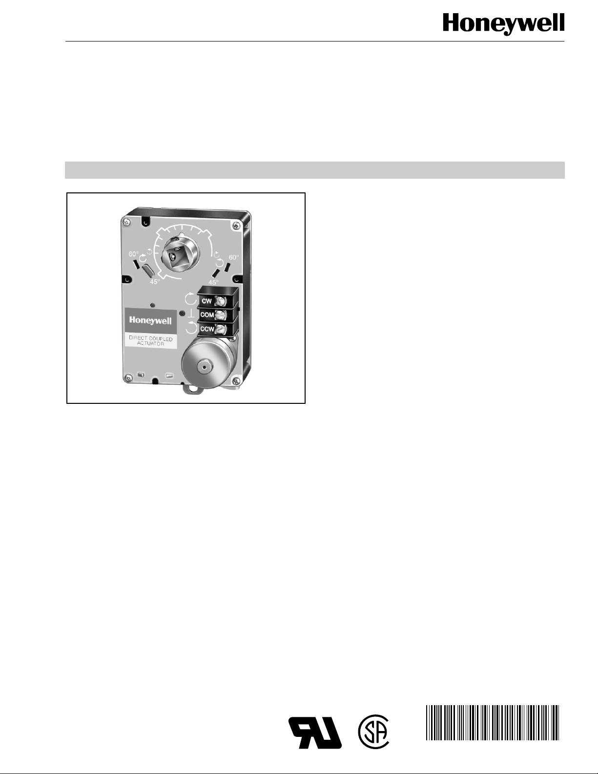
Direct Coupled Actuator
APPLICATION
The ML6131 Direct Coupl ed Act uator (DCA) is u sed to cont rol
dampers in applications such as variable air volume (VAV)
terminal units. It is suitable for use with single pole double
throw (spdt) floating thermostats or two-position control
systems.
ML6131
PRODUCT DATA
FEATURES
• Mounts directly on damper shaft.
• 6 lb-in. torque.
• Selectable 45°, 60°, and 90° stroke in either clockwise
(cw) or counterclockwise (ccw) directions.
• 15 second timing model s uitab le for use with pressure
independent VAV systems.
• Magnetic coupling typically provides a maximum of
18 lb-in. stall torque eliminating the need for
mechanical stops or limit switch adjustments.
• Two field-addable auxiliary switches.
• Field-addable auxiliary feedback potentiometer.
• Models available with 0° to 30° minimum position
adjustment in cw or ccw directions.
• Compatible for use with Honeywell W7620 Terminal
Unit Controller.
• Can be used with the Commercial Zone Damper in the
W7600 Commercial Zone System.
• Manual declutch on some models.
® U.S. Registered Trademark
Copyright © 2000 Honeywell Inc. • All Rights Reserved
Contents
Application ........................................................................ 1
Features ........................................................................... 1
Specifications ................................................................... 2
Ordering Information ........................................................ 2
Installation ........................................................................ 3
Operation .......................................................................... 8
Checkout .......................................................................... 8
®
63- 2498-2
Page 2

ML6131 DIRECT COUPLED ACTUATOR
SPECIFICATIONS
Models:
ML6131B: 6 lb-in. torque, selectable 45°, 60°, and 90° stroke
in both cw and ccw directions. 15 second timing, spdt
Floating Series 60, includes auxiliary potentiometer drive
for use with field-adda ble feedback potentiometer. Includes
minimum position adjustment setscrews for cw or ccw
operation. Includes 4074ENJ Bag Assembly.
Dimensions:
Electrical Ratings:
Power Consumption (Maximum), at 24 Vac:
2.4 VA.
Ambient Ratings:
Operating Temperature: 32°F to 130°F (0°C to 54°C).
Shipping and Storage: -20°F to 120°F (-29°C to 49°C).
Humidity: 5% to 95% RH noncondensing.
Torque Ratings:
Minimum Life Cycle Rating:
Repositions:
Actuator Timings (At 50 Hz Nominal):
90°-18 sec.
60°-12 sec.
45°-9 sec.
Actuator Timings (At 60 Hz Nominal):
90°-15 sec.
60°-10 sec.
45°-7.5 sec.
See Fig. 1.
Input Voltage: 24 Vac ±20%, 50/60 Hz.
2.2W, 0.095A,
See Table 1.
400,000.
1.5 million.
Feedback Potentiometer Ratings (ML6131B):
200976A,C Electrical Rating: 24 Vac, 50/60 Hz, 2.25 watts.
Resistance Output (Resistance Linear as Measured
Between Terminal R-B):
0 ohms (at 0 degree, cw stroke).
250 ohms (at 45 degree, cw stroke).
333 ohms (at 60 degree, cw stroke).
500 ohms (at 90 degree, cw stroke).
Auxiliary Switch Ratings:
not simultaneous.
Pilot Duty:
Switch Differential:
Approvals:
Underwriters Laboratories Inc. Component Recognized:
File No. E4436; Guide No. XAPX2.
CSA Certified (includes auxiliary switch).
Accessories:
201052A One Auxiliary Switch.
201052B Two Auxiliary Switch.
201052C Three Auxiliary Switch.
200976A 0 to 500 ohm Auxiliary Potentiometer.
200976C 0 to 2000 ohm Auxiliary Potentiometer.
4074ENJ Bag Assembly—includes stop pin, shaft adapter,
and minimum position screw.
4074ENY Bag Assembly—includes stop pin and shaft
adapter.
4074EVK Short Shaft Extensi on Kit—t o a dap t a ctu ato r ou tpu t
hub to short VAV damper shafts.
7640QW Metal Enclosure—for running conduit to actuator.
40 VA, 24 Vac.
Electrically selective NO or NC,
3 angular degrees maximum.
Damper Shaft Mounting:
• Suitable for mounting onto 3/8 to 1/2 in. square or round
damper shafts secured by two 1/4 in. 28 NF Allen screws.
• Minimum damper shaft length 1-3/4 in. (45 mm).
• Actuator may be mounted with actuator shaft in any
position.
Running 6 lb-in. (0.7 N•m)
Breakaway 6 lb-in. (0.7 N•m)
Stall (Typical) 7.5 lb-in. (0.8 N•m) minimum
Table 1. Torque Ratings.
Torque
18 lb-in. (2.0 N•m) maximum
ORDERING INFORMATION
When purchasing replacement and modernization products from your TRADELINE® wholesaler or distributor, refer to the
TRADELINE® Catalog or price sheets for complete ordering number.
If you have additional questions, need further information, or would like to comment on our products or services, please write or
phone:
1.
Your local Home and Building Control Sales Office (check white pages of your phone directory).
2.
Home and Building Control Customer Logistics
Honeywell Inc., 1885 Douglas Drive North
Minneapolis, Minnesota 55422-4386
In Canada—Honeywell Limited/Honeywell Limitée, 155 Gordon Baker Road, North York, Ontario M2H 3N7.
International Sales and Service Offices in all principal cities of the world. Manufacturing in Australia, Canada, Finland, France,
Germany, Japan, Mexico, Netherlands, Spain, Taiwan, United Kingdom, U.S.A.
63-2498—2 2
Page 3
CAUTION
CAUTION
CAUTION
3-3/8 (86)
ADD SPACER BETWEEN
DAMPER BOX AND TAB
DAMPER
SHAFT
ML6131
VAV BOX HOUSING
M4449
CW
COM
CCW
1 (25)
4-1/4
(108)
4-7/8
(123)
11/16
(18)
2-7/8 (73)
OPTIONAL
AUXILIARY
SWITCH
1-11/16
(42)
2-1/2 (64)
7/8
(22)
1-5/16
(33)
M18016
ML6131 DIRECT COUPLED ACTUATOR
Actuator Damage Hazard.
Deteriorating vapors and acid fumes can damage
the actuator metal parts.
1/8
(3)
Install actuator in areas free of acid fumes and
deteriorating vapors.
Location
Choose a location for the actuator that allows enough
clearance for mounting accessories and for servicing.
Mounting
These actuators are designed to open a damper or valve by
driving the shaft in either the clockwise (cw) or
counterclockwise (ccw) direction. The actuator has a
mounting tab on the botto m that sec ures it to a dampe r box or
valve linkage. When mounted correctly, this tab allows the
actuator to float without rota ting relative to the sh aft. The tab is
sized for 1/4 in. self-tapping sheet metal screws (not
included).
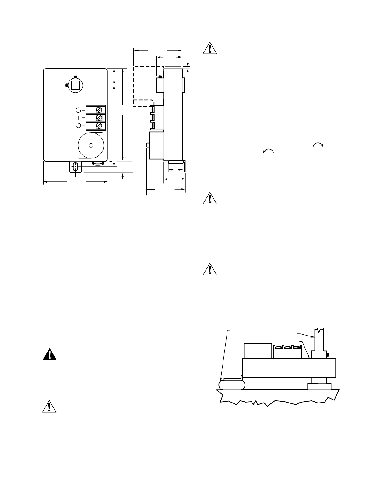
Fig. 1. Approximate dimensions of ML6131
Direct Coupled Actuator in in. (mm).
INSTALLATION
When Installing this Product...
1.
Read these instructio ns c aref ull y. Failure to follow them
could damage the product or cause a hazardous
condition.
2.
Check the ratings given in the instructions and on the
product to make sure the product is suitable for your
application.
3.
Installer must be a trained, experienced service
technician.
4.
After installation is complete, check out product
operation as provided in these instructions.
IMPORTANT
All wiring must agree with applicable codes,
ordinances and regulations.
WARNING
Explosion Hazard.
A spark from the actu ator or attached accessori es
can result in serious injury or death.
Install the actuator in areas free of escaping gas and
other explosive vapors.
Equipment Damage Hazard.
Tightly securing mounting tab to damper housing
can damage actuator.
Once mounted, the actuator must be allowed to float;
do not fully tighten the screw.
These actuators are ship ped in the fully cl ockwise 90° pos ition
as viewed from the end of the damper shaft.
Equipment Damage Hazard.
Mounting actuator unevenly with damper housing
can damage actuator.
Mount actuator flush with damper housing or add
spacer between mounting tab and damper box
housing (see Fig. 2).
CAUTION
Electrical Shock or Equipment Damage Hazard.
Can shock individuals or short equipment
circuitry.
Disconnect all power supplies before installation.
Actuators with auxiliary switches can have more than
one disconnect.
Fig. 2. Mounting actuator to VAV box when
actuator is not flush with box.
3 63-2498—2
Page 4

ML6131 DIRECT COUPLED ACTUATOR
Preparation
Before mounting the actuator onto the shaft, determine the
following:
1.
Size of the shaft (3/8 in. to 1/2 in.).
2.
Direction the shaft rotates to open the device (cw or
ccw). See Fig. 3.
3.
Degrees of actuator stro ke for openin g device (4 5°, 60°,
or 90°).
If the shaft is 3/8 i n. roun d or square , use pa rt num ber 20 1391
Shaft Adapter provided inside the bag as sem bl y sh ipp ed with
the actuator. Place the adapter opposite the setscrews
(see Fig. 4).
MANUAL
DECLUTCH
LEVER
DIRECT COUPLED ACTUATOR
ML6131
ML6131
M17611
TYPE A DAMPER
COOLING
AIR FLOW
CW TO OPEN, CCW TO CLOSE
TYPE B DAMPER
COOLING
AIR FLOW
CCW TO OPEN, CW TO CLOSE
Fig. 3. Determining direction damper
shaft rotates when opening.
SHAFT ADAPTER
Fig. 4. Using shaft adapter for 3/8 in. shafts.
Manual Operation (Declutch)
M2067A
M2064
Fig. 5. Location of manual declutch lever.
Installation
After determining the direction of the shaft rotation (cw or
ccw), install the device. For valve linkage mounting, refer to
the instructions shipped with the linkage. For damper
mounting, proceed as follows :
1.
Place the actuator onto the damper shaft .
CAUTION
Equipment Damage Hazard.
Improper range stop selection can damage
light-duty dampers.
Be sure to select the proper range stop.
2.
If the angle of the damper opening is either 45° or 60°,
close the actuator using the manual declutch:
a. Disengage the hub using the declutch lever; see
Manual Operation (Declutch) section.
b. Rotate the hub until the actuator gear train passes
the proper 45° or 60° setting. (Do not insert the pin
until after the actuator passes this point.)
c. Release the declutch lever.
NOTE: Dampers with 90° stroke do not require the
3.
Insert the range stop pin into the appropriate (cw or
ccw) 45° or 60° slot. The range stop pin is clipped into
its final position only after the pin passes through both
actuator plates (see Fig. 6). The range stop pin should
snap into position and not be removable manually
(see Fig. 7).
range stop pin.
IMPORTANT
CAUTION
Do not fully tighten the mounting screw; the actuator
must be allowed to float.
Personal Injury and Product Damage Hazard.
Do not use manual declutch without supporting
the load.
Support load independent of actuator immediately
prior to and while using manual declutch lever.
4.
With the actuator placed in its final position, secure the
mounting tab to the damper box with a sheet metal
screw.
5.
Position the damper in the open position and securely
tighten the Allen screws into the damper shaft.
Manual declutch capability is available on some actuators.
Use the manual declutch lev er to manually adjust the actua tor
setting. Fig. 5 show s the l ocation of the manual declutc h lever.
To operate, push the lever in the direction of the arrow on the
lever cover.
63-2498—24
Page 5

ML6131 DIRECT COUPLED ACTUATOR
CAUTION
1.
Determine the direction of the desired closing rotation.
2.
RANGE STOP PIN
Move the actuator to the position fully opposite the
desired closing rotatio n (if cw clo sing rotation is desire d,
move the actuator to the full ccw position).
3.
Determine the correct hole for the sets crew usin g Fig. 8
ACTUATOR PLATES
60
and the results of step 1.
THIS SETSCREW
CORRESPONDS WITH
CLOSING IN THE
CW DIRECTION
THIS SETSCREW
CORRESPONDS WITH
CLOSING IN THE
CCW DIRECTION
45
60
45
CW
COM
CCW
M10246A
Fig. 6. Range stop pin properly inserted.
SCREWDRIVER
M2065
Fig. 7. Lifting a range stop pin out of its slot.
Minimum Position Setscrew
Certain ML6131 models are equipped with two tapped holes
located in the plas tic h ous in g at the top of the actuator. These
holes can be used with the minimum position setscrew and
locknut inside the 4074ENJ Bag Assembly (see Fig. 6). The
setscrew provides for a 0° to 30° minimum position
adjustment.
NOTE: Before starting operation, note that the 1/4 in.
minimum position setscrew limits closing motion,
while the range stop pin limits opening motion.
60
45
60
45
Fig. 8. Setscrew location for ML6131.
Equipment Damage Hazard.
Improper hub positioning or hole selection can
permanently damage the device.
Avoid backdriving the actuator with the setscrew.
4.
Remove the red cap from the desired hole. Leave the
other cap in position. The caps ensure that dust and
other impurities do not enter the gear train through
unused holes.
5.
Thread the locknut fully onto the 1/4 in. setscrew.
6.
Insert the setscrew into the desired hole, turning
clockwise until resistance is encountered or the locknut
contacts the housing.
7.
If resistance is met be fore the setscrew is fully inserted ,
stop and review the initial setup procedures as detailed
in steps 1 through 3.
8.
Determine the angle of minimum position required for
the application. With the setscrew fully inserted, the
minimum position is 30 °. W ith the s etscre w fully out, the
minimum position is 0°.
9.
Using the conversion of approximately 1.7 angular
degrees of shaft rotation per turn of the setscrew, back
the screw out of the housing and stop slightly short of
the calculated position. This allows the setscrew to be
set accurately while taking air flow measurements.
IMPORTANT
After initiating step 10, the setscrew cannot be
turned into the housing without returning the actuato r
to the fully open position (as determined in step 1).
The actuator follows the setscrew without damaging
the housing only when backed out of the housing
(turned ccw).
M10247
5 63-2498—2
Page 6

ML6131 DIRECT COUPLED ACTUATOR
10.
Rotate the actuator to minimum position using the
manual declutch; see Manual Operation (Declutch)
section.
11.
With the actuator at minimum position, adjust the
position more accurately using air flow measurements.
IMPORTANT
— After each adjustment, ensure the actuator is
completely stopped before proceeding with the next
adjustment.
— To reduce the minimum position, turn out the
setscrew (ccw). The actuator then drives toward the
closed position.
— Turning the setscrew in (cw) damages the actuator
housing.
— If the device is too far closed, return to step 1.
12.
When proper air flow is achieved, loosen the locknut
from the setscrew until it contac ts the actua tor hou sing,
then turn it an additional 1/8 turn to lock the setscrew in
place.
IMPORTANT
Run an entire check of the operation after complet ing
this procedure.
Wiring
The 201052A, B and C Auxiliary Switches are field-addable.
For mounting instructions, see form 63-22 18, prov id ed with
the device.
IMPORTANT
When operating an ML6131 from a two-position
controller, a 201052B Auxiliary Switch is required for
proper operation. See Fig. 10.
NOTE: See Fig. 11 for the 201052B Auxiliary Switch wiring.
2
EXTERNAL
SWITCH
1
L1
(HOT)
L2
1
POWER SUPPLY. PROVIDE DISCONNECT MEANS
AND OVERLOAD PROTECTION AS REQUIRED.
AUXILIARY SWITCHES ARE REQUIRED TO TURN
2
OFF THE MOTOR AT EACH END OF THE STROKE.
T87F
W
Y
R
R8222
ML6131
RED COM
BLUE CW
WHITE CCW
M17613
CAUTION
Electrical Shock or Equipment Damage Hazard.
Can shock individuals or short equipment
circuitry.
Disconnect all power supplies before installation.
Actuators with auxiliary switches can have more than
one disconnect.
All wiring must comply with local electrical codes, ordinances
and regulations. Voltage and frequency of the transformer
used with the actuator must correspond with the
characteristics of both the power supply and the actuator.
Screw terminals are provided for easy hookup. See Fig. 9 for
typical wiring.
Auxiliary Switches
The 201052A, B or C Auxiliary Switch is used in conjunction
with the actuator. It allows for control of equipment ext erna l to
the actuator (for example, electric reheat coils and fan) at an
adjustable point in the stroke (0° to 90°) of the actuator.
Fig. 9. ML6131 used with T87F in heating-only
or cooling-only application.
2
3
ML6131
RED COM
BLUE CW
WHITE CCW
L1
(HOT)
L2
1
4
1
POWER SUPPLY. PROVIDE DISCONNECT MEANS AND OVERLOAD
PROTECTION AS REQUIRED.
SET SWITCH TO CLOSE WHEN STROKE REACHES FULL CW POSITION.
2
3
SET SWITCH TO CLOSE WHEN STROKE REACHES FULL CCW POSITION.
ON-OFF CONTROL REQUIRES AN R8222 SPDT RELAY IN PLACE OF THE
4
SPDT CONTROL.
SPDT
CONTROL
ON/OFF
CONTROL
201052B
Fig. 10. 201052B Auxiliary Switch wiring.
M17612
63-2498—26
Page 7

ML6131 DIRECT COUPLED ACTUATOR
Auxiliary Potentiometers
The 200976 Auxiliary Potentiometer mounts on the face of
certain ML6131A actuators as shown in Fig. 11. The
potentiometer shaft has a slipping collar, which means that if
one of the two limits of the potentiometer is exceeded, the
collar will continue to rotate, causing no damage to the
potentiometer itself. To mount the potentiometer on the
actuator:
1.
Turn the potentiometer to align the shaft key with the
slot in the potentiometer drive.
2.
Tilt the potentiometer slightly so the key faces down
toward the slot.
3.
Insert the potentiom eter int o the sl ot, and p ush do wn so
the potentiometer is flush with the actuator body and the
bracket is aligned over the screw hole.
4.
Insert the screw provided into the hole and fasten
securely.
IMPORTANT
To Calibrate the 200976A,C:
IMPORTANT
Failure to follow the calibrati on procedures can resu lt
in improper resistance values at desired stroke.
Remove the range stop pins and minimum position
setscrews prior to calibration.
1.
Drive the actuator fully closed (0°) to fully open (90°)
and back again to th e fully cl osed posi tion. This must be
done to receive the correct resistance readings at the
appropriate degree of stroke.
2.
Check the resistance values of the potentiometer with
an ohmmeter at intervals in the stroke while referring to
the table in Fig. 11 and resistance information provided
in the Specifications section.
3.
Replace the range stop pins and/or the minimum
position setscrews using the appropriate procedures.
MOTOR
POSITION
FULLY CW
24V (COM-CW)
FULLY CCW
24V (COM-CCW)
MOTOR
ROTATION
CCW
CW
AUXILIARY POTENTIOMETER
R
W
RB
RESISTANCE
500 OR
2000 OHMS
0 OHMS
DECREASE
INCREASE
45
RW
RESISTANCE
0 OHMS
500 OR
2000 OHMS
AUXILIARY POTENTIOMETER LEADS
RW OHMS RB OHMS
INCREASE
DECREASE
60
45
B
60
CW
COM
CCW
FIELD-ADDABLE AUXILIARY POTENTIOMETER
M10251B
Fig. 11. ML6131 with field-addable potentiometer.
7 63-2498—2
Page 8

Printed in U.S.A. on recycled
paper containing at least 10%
post-consumer paper fibers.
ML6131 DIRECT COUPLED ACTUATOR
OPERATION
VAV Systems
VAV systems control the temperature within a space by
varying the volume of supply air. Air is delivered to the space
at a fixed temperature. The volume of supply air is controlled
by the space thermostat modulating the supply air damper.
When full heating a nd coolin g flexibi lity is requir ed in a zon e, it
is handled by tempe rature a ir system, o r with reh eat capab ility
in the air terminal units. As individual zones shut down, the
total air flow in the sys tem is regu lat ed b y a c ent ral d uc t sta t ic
pressure controller. The fan system is sized to handle an
average peak load, not the sum of the individual peaks. As
each zone peaks at a different time of day, extra air is
borrowed from the off-peak zones. This transfer of air from
low-load to high-load zo nes occurs only in true VAV systems.
In pressure independent systems, individual zone airflow
sensors are used to m aintain t he zone air fl ow ra te regard less
of fluctuation in the total system pressure.
Pressure independent systems, when used with controllers
such as the W7620, can react faster to changes in air flow
demand. Therefore, these systems can use the faster
15 second ML6131 models.
Parallel Actuators
IMPORTANT
Over time, paralle l-d riv ing actuators can bec ome o ut
of sync with each other. Normally, driving all
actuators to the fully-open or fully-closed position
puts them back in sync.
CHECKOUT
To check out the ML6131, determine the direction the damper
shaft moves to open the damper (cw or ccw). See Fig. 3:
1.
Place 24 Vac across the appropriate COM and CW or
COM and CCW terminals to energize the actuator. The
ML6131 should begin to open the damper.
2.
If the actuator does not run, switch the 24 Vac across
the opposite COM and CW or CO M and CCW termina ls
to determine if the damper will begin to close.
3.
If the actuator does not run in either direction, replace
the ML6131.
In the event the ML6131 is used with a spdt floating wall
thermostat (pressure dependent systems):
1.
Adjust the setpoint of the thermostat to call for cooling.
2.
Observe the operation of the actuator; if the device is
closed, it should begi n to open.
3.
If not, adjust the setpoint of the thermostat higher to
determine if the wiring is correct.
4.
If no movement is observed, check for the presence of
24 volts.
5.
If using the T641 Thermostat, check that 24 volts are
present between terminals C and Y during a call for
cooling. With proper wiring and 24 volts present, the
actuator should operate correctly.
6.
If not, replace the actuator.
NOTE: When the ML6131 is used with electronic
control systems such as the W7620, overri de
the control system by programming the
controller to open/close the zone dam per as
appropriate.
Using Fig. 9, paral lel the C W , C OM and C CW terminal s. Make
certain the total connected load does not exceed the current
capacity of the controller or thermostat.
Home and Building Control Home and Building Control
Honeywell Inc. Honeywell Limited-Honeywell Limi tée
Honeywell Plaza 155 Gordon Baker Road
P.O. Box 524 North York, Ontario
Minneapolis, MN 55408-0524 M2H 3N7
63-2498—2 B.B. Rev. 6-00 www.honeywell.com
 Loading...