

Page 1

Airlines & Avionics Products
Honeywell Inc.
15001 N.E. 36th Street
Redmond, WA 98052
MK VI
MK VIII
Enhanced Ground Proximity Warning System
(Class A TAWS)
Installation Design Guide
Hardware/Software Part Numbers:
965-1180-020
965-1190-020
965-1210-020
965-1220-020
Release Date: July 14, 2003
Proprietary notice on title page applies
CAGE CODE: 97896 SCALE: NONE SIZE: A DWG NO: 060-4314-150 REV:
SHEET
1 OF 326
Page 2

Honeywell
MK VI MK VIII EGPWS Installation Design Guide
Copyright 2003 Honeywell, Inc. All rights reserved.
This document and all information and expression contained herein are the property of Honeywell International
Inc., and is provided to the recipient in confidence on a “need to know” basis. Your use of this document is strictly
limited to a legitimate business purpose requiring the information contained therein. Your use of this document
constitutes acceptance of these terms.
Proprietary notice on title page applies
CAGE CODE: 97896 SCALE: NONE SIZE: A DWG NO: 060-4314-150 REV:
SHEET
2
Page 3
Typed names constitute approval signatures. Actual signatures are on file at Honeywell in
Redmond, WA.
Honeywell
MK VI MK VIII EGPWS Installation Design Guide
SHEET
NUMBER
REV
LTR
SHEET
NUMBER
DRAWN
Larry Matter 14-JULY-03
CHECK
ENGR
Larry Matter 14-JULY-03
MFG
QA
APVD
Jim Mulkins 14-JULY-03
APVD
REVISION STATUS OF SHEETS INDEX
ADDED SHEETS ADDED SHEETS
REV
LTR
SHEET
NUMBER
REV
LTR
SHEET
NUMBER
REV
LTR
SHEET
NUMBER
REV
LTR
SHEET
NUMBER
REV
LTR
REVISIONS
SH REV DESCRIPTION DATE APPROVED
Proprietary notice on title page applies
CAGE CODE: 97896 SCALE: NONE SIZE: A DWG NO: 060-4314-150 REV:
SHEET
3
Page 4

Honeywell
MK VI MK VIII EGPWS Installation Design Guide
THIS PAGE INTENTIONALLY LEFT BLANK
Proprietary notice on title page applies
CAGE CODE: 97896 SCALE: NONE SIZE: A DWG NO: 060-4314-150 REV:
SHEET
4
Page 5

Honeywell
MK VI MK VIII EGPWS Installation Design Guide
TABLE OF CONTENTS
SECTION I – GENERAL INFORMATION ..........................................................................................................13
1.1 I
NTRODUCTION.........................................................................................................................................................13
1.2 A
PPLICABILITY.........................................................................................................................................................13
1.3 H
OW TO USE THIS DOCUMENT ................................................................................................................................13
1.4 R
EFERENCE DOCUMENTS .........................................................................................................................................14
1.5 D
ESCRIPTION OF EQUIPMENT ...................................................................................................................................15
1.5.1 MK VI EGPWS Computer .................................................................................................................................... 15
1.5.2 MK VIII EGPWS Computer..................................................................................................................................15
1.5.3 MK VI/MK VIII EGPWS Configuration Module ..................................................................................................15
1.5.4 GPS Antenna and Cabling....................................................................................................................................16
1.5.5 OAT Sensor ..........................................................................................................................................................17
1.5.6 Smart Cable (PCMCIA Interface)........................................................................................................................17
1.6 T
ECHNICAL CHARACTERISTICS ................................................................................................................................18
1.7 U
NITS SUPPLIED.......................................................................................................................................................18
1.7.1 MK VI EGPWS .....................................................................................................................................................18
1.7.2 MK VIII EGPWS.................................................................................................................................................19
1.7.3 Configuration Module ........................................................................................................................................19
1.7.4 Smart Cable (PCMCIA Interface) ...................................................................................................................... 19
1.8 I
NSTALLATION KITS AND ACCESSORIES .................................................................................................................19
1.8.1 MK VI/MK VIII EGPWS Installation Kits ..........................................................................................................19
1.8.2 RS-232 Cable......................................................................................................................................................20
1.8.3 Smart Cable........................................................................................................................................................20
1.8.4 Terrain Database Cards.....................................................................................................................................20
1.8.5 Flight History Card ............................................................................................................................................20
1.9 A
CCESSORIES NOT SUPPLIED ..................................................................................................................................20
1.9.1 ARINC 453 Terrain Display wiring....................................................................................................................20
1.9.2 GPS Antenna & Cable........................................................................................................................................21
1.9.3 Circuit Breaker...................................................................................................................................................21
1.9.4 Annunciators & Switch/Annunciators ................................................................................................................22
1.9.5 Cockpit Speakers ................................................................................................................................................23
1.9.6 Temperature Probes ...........................................................................................................................................23
1.10 T
OOLS REQUIRED .................................................................................................................................................24
1.10.1 Crimping Tool - P1, P2, P3.............................................................................................................................24
1.10.2 Contact Positioner - P1, P2, P3 ......................................................................................................................24
1.10.3 Insertion/Removal Tool - P1, P2, P3............................................................................................................... 24
1.10.4 Spare Connectors and Contacts - P1, P2, P3..................................................................................................25
1.11 L
ICENSE REQUIREMENTS......................................................................................................................................25
SECTION II - INSTALLATION ............................................................................................................................. 29
Proprietary notice on title page applies
CAGE CODE: 97896 SCALE: NONE SIZE: A DWG NO: 060-4314-150 REV: SHEET 5
Page 6

Honeywell
MK VI MK VIII EGPWS Installation Design Guide
2.1 INTRODUCTION....................................................................................................................................................... 29
2.2 U
NPACKING AND INSPECTING THE EQUIPMENT ......................................................................................................29
2.3 E
QUIPMENT INSTALLATION ....................................................................................................................................29
2.3.1 General...............................................................................................................................................................29
2.3.2 MK VI/MK VIII Computer Location...................................................................................................................29
2.3.3 MK VI/ MK VIII Computer Installation..............................................................................................................30
2.3.4 Configuration Module Location .........................................................................................................................31
2.3.5 Configuration Module Installation.....................................................................................................................31
2.3.6 GPS Antenna location.........................................................................................................................................40
2.3.7 GPS Antenna Installation ...................................................................................................................................40
2.3.8 OAT Sensor Location..........................................................................................................................................40
2.3.9 OAT Sensor Installation .....................................................................................................................................40
2.3.10 Cockpit Lights...................................................................................................................................................40
2.3.10.1 Description........................................................................................................................................................................ 41
2.3.10.2 Location............................................................................................................................................................................ 42
SECTION III – SYSTEM PLANNING................................................................................................................... 51
3.1 I
NTRODUCTION.......................................................................................................................................................51
3.2 S
YSTEM WIRING/ ELECTRICAL INTERFACES .......................................................................................................... 51
3.2.1 Primary Power Input..........................................................................................................................................51
3.2.2 Chassis Ground ..................................................................................................................................................52
3.2.3 GPS Antenna ......................................................................................................................................................52
3.2.4 Analog and Digital Inputs ..................................................................................................................................52
3.2.5 Discrete Inputs....................................................................................................................................................52
3.2.6 Serial Outputs.....................................................................................................................................................52
3.2.7 Audio Output.......................................................................................................................................................53
3.2.8 Discrete Outputs.................................................................................................................................................53
3.2.9 Configuration Module ........................................................................................................................................53
3.3 C
ATEGORY 1 - AIRCRAFT / MODE TYPE SELECT ...................................................................................................54
3.3.1 Aircraft / Mode Type...........................................................................................................................................54
3.3.2 Mode 1 type ........................................................................................................................................................54
3.3.3 Mode 2 type ........................................................................................................................................................54
3.3.4 Mode 3 type ........................................................................................................................................................55
3.3.5 Mode 4 type ........................................................................................................................................................55
3.3.6 Bank Angle Type.................................................................................................................................................55
3.3.7 Runway Length (MK VIII EGPWS only) ............................................................................................................56
3.3.8 Instructions.........................................................................................................................................................56
3.4 C
ATEGORY 2 – AIR DATA INPUT SELECT ...............................................................................................................57
3.4.1 Analog (Cat. 2 ID 0, 3, 4, 11, 12) ....................................................................................................................... 57
3.4.2 Digital – ARINC 429 (Cat. 2 ID 5, 1, 6, 13).......................................................................................................59
3.4.3 Digital –ARINC 575 (Cat. 2 ID 2)......................................................................................................................60
3.4.4 Shadin 2000 (Cat. 2 ID 10).................................................................................................................................61
3.4.5 Digital – ARINC 429 Dual IOC Buses (Cat. 2. ID 255).....................................................................................62
Proprietary notice on title page applies
CAGE CODE: 97896 SCALE: NONE SIZE: A DWG NO: 060-4314-150 REV: SHEET 6
Page 7

Honeywell
MK VI MK VIII EGPWS Installation Design Guide
3.4.6 Instructions.........................................................................................................................................................62
3.5 C
ATEGORY 3 – POSITION INPUT SELECT ................................................................................................................63
3.5.1 ARINC 743 Format.............................................................................................................................................63
3.5.2 GPS Altitude (Label 076) Reference...................................................................................................................63
3.5.3 North-South East-West Velocity labels...............................................................................................................63
3.5.4 ARINC 429 BUS (Cat. 3 ID 0,1,4,5,10-13).........................................................................................................64
3.5.5 RS-232 Transmit-Receive, 9600 baud (Cat. 3 ID 3)...........................................................................................65
3.5.6 Dual ARINC 429 BUS (Cat. 3 ID 253 & 255).................................................................................................... 66
3.5.7 Instructions.........................................................................................................................................................66
3.6 C
ATEGORY 4 – ALTITUDE CALLOUTS ....................................................................................................................67
3.7 C
ATEGORY 5 – AUDIO MENU SELECT ....................................................................................................................68
3.7.1 Audio Menu Selection.........................................................................................................................................68
3.7.2 Instructions.........................................................................................................................................................68
3.8 C
ATEGORY 6 – TERRAIN DISPLAY SELECT.............................................................................................................69
3.8.1 TAD & TCF Selection.........................................................................................................................................69
3.8.2 Terrain Display Configuration Group................................................................................................................70
3.8.3 Display Input Control Group..............................................................................................................................70
3.8.4 Output 429 Bus Group........................................................................................................................................71
3.8.5 Instructions.........................................................................................................................................................71
3.8.6 Sample Display Schematics................................................................................................................................71
3.9 C
ATEGORY 7 – OPTIONS SELECT GROUP #1........................................................................................................... 88
3.9.1 Steep Approach...................................................................................................................................................88
3.9.2 TA&D Alternate Pop-up.....................................................................................................................................88
3.9.3 Peaks Mode ........................................................................................................................................................88
3.9.4 Obstacle Awareness............................................................................................................................................88
3.9.5 Bank Angle Callout Enabling.............................................................................................................................89
3.9.6 Flap Reversal......................................................................................................................................................89
3.9.7 GPS Altitude Reference ......................................................................................................................................89
3.9.8 Instructions.........................................................................................................................................................90
3.10 C
ATEGORY 8 – RADIO ALTITUDE INPUT SELECT..................................................................................................91
3.10.1 Radio Altitude Input..........................................................................................................................................91
3.10.2 Decision Height Discrete Input ........................................................................................................................ 91
3.10.3 Digital Radio Altitude Interface (Cat. 8 ID 2).................................................................................................. 91
3.10.4 Analog Radio Altitude Interface (Cat. 8 ID 0,1,3,4).........................................................................................92
3.10.5 Digital – ARINC 429 Dual IOC Buses (Cat. 8 ID 251- 255)............................................................................92
3.10.6 Instructions .......................................................................................................................................................93
3.11 C
ATEGORY 9 – NAVIGATION INPUTS SELECT.......................................................................................................94
3.11.1 Navigation Inputs Select (Glideslope & Localizer Inputs) ...............................................................................94
3.11.2 Glideslope Validity ........................................................................................................................................... 94
3.11.3 Localizer Validity .............................................................................................................................................94
3.11.4 ILS Tuned Discrete Input #1 (+28V) and #2 (GND) ........................................................................................ 94
3.11.5 Analog Glideslope Interface (Cat. 9 ID 0,1,5)..................................................................................................95
3.11.6 Digital Glideslope / Localizer / ILS Select Interface (Cat. 9 ID 2,3,4).............................................................96
Proprietary notice on title page applies
CAGE CODE: 97896 SCALE: NONE SIZE: A DWG NO: 060-4314-150 REV: SHEET 7
Page 8

Honeywell
MK VI MK VIII EGPWS Installation Design Guide
3.11.7 Digital – ARINC 429 Dual IOC buses (Cat. 9 ID 250 - 255)...........................................................................96
3.11.8 Instructions .......................................................................................................................................................97
3.12 C
ATEGORY 10 – ATTITUDE INPUT SELECT ...........................................................................................................98
3.12.1 Roll Angle .........................................................................................................................................................98
3.12.2 Analog Pitch & Roll Angle (Synchro) (Cat. 10 ID 0,2,4) .................................................................................98
3.12.3 Digital Pitch & Roll Angle (ARINC 429 High Speed) (Cat. 10 ID 5 & 6)........................................................99
3.12.4 Digital – ARINC 429 Dual IOC buses (Cat. 10 ID 253 & 255) ....................................................................... 99
3.12.5 Instructions .......................................................................................................................................................99
3.13 C
ATEGORY 11 – HEADING INPUT SELECT ..........................................................................................................100
3.13.1 Magnetic Heading ..........................................................................................................................................100
3.13.2 Analog Heading (Synchro) (Cat. 11 ID 0)...................................................................................................... 100
3.13.3 Digital – ARINC 429 AHRS Input (Cat. 11 ID 2 & 3).................................................................................... 101
3.13.4 Digital – ARINC 429 Dual IOC buses (Cat. 11 ID 254 & 255) ..................................................................... 101
3.13.5 Instructions .....................................................................................................................................................101
3.14 C
ATEGORY 12 – WINDSHEAR INPUT SELECT ..................................................................................................... 102
3.14.1 No Windshear ................................................................................................................................................. 102
3.14.2 Dual ARINC 429 BUS (Cat. 14 ID 253,254,255)...........................................................................................102
3.14.3 Instructions .....................................................................................................................................................102
3.15 C
ATEGORY 13 – INPUT / OUTPUT DISCRETE TYPE SELECT ................................................................................103
3.15.1 Input Discretes................................................................................................................................................103
3.15.1.1 Glideslope Inhibit Discrete ............................................................................................................................................. 103
3.15.1.2 Landing Flaps Discrete ................................................................................................................................................... 103
3.15.1.3 Audio Inhibit Discrete..................................................................................................................................................... 104
3.15.1.4 Landing Gear Discrete.................................................................................................................................................... 104
3.15.1.5 Glideslope Cancel Discrete............................................................................................................................................. 106
3.15.1.6 Momentary Flap Override Discrete................................................................................................................................. 106
3.15.1.7 Mode 6 Low Volume Discrete........................................................................................................................................ 106
3.15.1.8 Autopilot Engaged Discrete............................................................................................................................................ 107
3.15.1.9 Terrain Awareness and TCF Inhibit Discrete.................................................................................................................. 107
3.15.1.10 Self Test Discrete.......................................................................................................................................................... 107
3.15.1.11 Steep Approach Discrete #2.......................................................................................................................................... 108
3.15.1.12 GPWS INHIBIT Discrete (alternate action).................................................................................................................. 108
3.15.2 Output Discretes.............................................................................................................................................108
3.15.2.1 Lamp Format................................................................................................................................................................... 109
3.15.2.2 Flashing Lamps............................................................................................................................................................... 109
3.15.2.3 GPWS INOP Discrete..................................................................................................................................................... 109
3.15.2.4 TAD INOP Discrete........................................................................................................................................................ 109
3.15.2.5 GPWS Warning Discrete ................................................................................................................................................ 109
3.15.2.6 GPWS Alert Discrete...................................................................................................................................................... 110
3.15.2.7 Glideslope Cancel’d Discrete.......................................................................................................................................... 110
3.15.2.8 Flap Override Discrete.................................................................................................................................................... 110
3.15.2.9 Steep Approach Discrete................................................................................................................................................. 110
3.15.2.10 Audio On Discrete (TCAS/TAS Inhibit)....................................................................................................................... 110
Proprietary notice on title page applies
CAGE CODE: 97896 SCALE: NONE SIZE: A DWG NO: 060-4314-150 REV: SHEET 8
Page 9

Honeywell
MK VI MK VIII EGPWS Installation Design Guide
3.15.2.11 Terrain Display Select #1 & #2 Discrete....................................................................................................................... 111
3.15.2.12 Terrain Pop up Discrete ................................................................................................................................................ 112
3.15.3 Instructions .....................................................................................................................................................113
3.16 C
ATEGORY 14 – AUDIO OUTPUT LEVEL ............................................................................................................ 113
3.16.1 Instructions .....................................................................................................................................................113
3.17 C
ATEGORY 15 - 17 – UNDEFINED INPUT SELECTS ............................................................................................. 114
3.17.1 Undefined Input Select....................................................................................................................................114
3.17.2 Instructions .....................................................................................................................................................114
SECTION IV – CONFIG MODULE PROGRAMMING AND REGIONAL TDB LOADING ......................117
4.1 I
NTRODUCTION.....................................................................................................................................................117
4.2 H
ARNESS CHECKOUT AND POWER CHECK ...........................................................................................................117
4.3 U
NIT INSTALLATION.............................................................................................................................................117
4.4 EGPWC I
NITIALIZATION AND CONFIGURATION ..................................................................................................117
4.4.1 RS-232 Communication with the MK VI/VIII EGPWS ..................................................................................... 117
4.4.2 EGPWC Front Panel Test Connector...............................................................................................................118
4.4.3 WinVIEWS ........................................................................................................................................................119
4.4.4 WinVIEWS Operation....................................................................................................................................... 119
4.5 C
ONFIGURATION MODULE PROGRAMMING..........................................................................................................119
4.5.1 CUW and CMR Commands..............................................................................................................................121
4.5.2 Configuration Module Reprogramming ........................................................................................................... 122
4.6 T
ERRAIN DATABASE LOADING.............................................................................................................................122
4.6.1 Effectivity..........................................................................................................................................................122
4.6.2 Description .......................................................................................................................................................123
4.6.3 Approval ...........................................................................................................................................................123
4.6.4 Material – Cost and Availability ......................................................................................................................123
4.6.5 Accomplishment Instructions............................................................................................................................ 123
4.6.6 Verification of the Terrain Database Version ..................................................................................................125
SECTION V – CERTIFICATION......................................................................................................................... 128
5.1 I
NTRODUCTION.....................................................................................................................................................128
5.2 C
ERTIFICATION PROCEDURE ................................................................................................................................128
5.2.1 Equipment Compatibility ..................................................................................................................................128
5.2.2 Equipment Location..........................................................................................................................................128
5.2.3 FAA Requirements............................................................................................................................................ 128
5.2.4 Ground Test ......................................................................................................................................................128
5.2.5 Flight Manual Revision ....................................................................................................................................128
5.2.6 Flight Test.........................................................................................................................................................128
5.2.7 Pilots Guide......................................................................................................................................................129
5.2.8 Failure Modes, Effects, and Safety Analysis.....................................................................................................129
SECTION VI - MK VI GPWS TO MK VI/VIII EGPWS SIGNAL MAPPING ...............................................131
Proprietary notice on title page applies
CAGE CODE: 97896 SCALE: NONE SIZE: A DWG NO: 060-4314-150 REV: SHEET 9
Page 10

Honeywell
MK VI MK VIII EGPWS Installation Design Guide
APPENDIX A - CUSTOMER WORKSHEET .....................................................................................................137
APPENDIX B - SAMPLE WIRING DIAGRAMS ............................................................................................... 141
APPENDIX C – WINVIEWS OPERATION INSTRUCTIONS.........................................................................146
APPENDIX D - VENDOR CONTACT INFORMATION...................................................................................150
APPENDIX E – INTERFACE DESCRIPTION DOCUMENT .......................................................................... 153
Proprietary notice on title page applies
CAGE CODE: 97896 SCALE: NONE SIZE: A DWG NO: 060-4314-150 REV: SHEET 10
Page 11

Honeywell
MK VI MK VIII EGPWS Installation Design Guide
SECTION I
GENERAL INFORMATION
Proprietary notice on title page applies
CAGE CODE: 97896 SCALE: NONE SIZE: A DWG NO: 060-4314-150 REV:
SHEET
11
Page 12

Honeywell
MK VI MK VIII EGPWS Installation Design Guide
SECTION I – GENERAL INFORMATION
SECTION I – GENERAL INFORMATION ..................................................................................................................... 13
1.1 I
NTRODUCTION.............................................................................................................................................................. 13
1.2 A
PPLICABILITY.............................................................................................................................................................. 13
1.3 H
OW TO USE THIS DOCUMENT ..................................................................................................................................... 13
1.4 R
EFERENCE DOCUMENTS .............................................................................................................................................. 14
1.5 D
ESCRIPTION OF EQUIPMENT ........................................................................................................................................ 15
1.5.1 MK VI EGPWS Computer ..................................................................................................................................... 15
1.5.2 MK VIII EGPWS Computer................................................................................................................................... 15
1.5.3 MK VI/MK VIII EGPWS Configuration Module ................................................................................................... 15
1.5.4 GPS Antenna and Cabling..................................................................................................................................... 16
1.5.5 OAT Sensor ........................................................................................................................................................... 17
1.5.6 Smart Cable (PCMCIA Interface)......................................................................................................................... 17
1.6 T
ECHNICAL CHARACTERISTICS ..................................................................................................................................... 18
1.7 U
NITS SUPPLIED............................................................................................................................................................ 18
1.7.1 MK VI EGPWS ...................................................................................................................................................... 18
1.7.2 MK VIII EGPWS ................................................................................................................................................... 19
1.7.3 Configuration Module ........................................................................................................................................... 19
1.7.4 Smart Cable (PCMCIA Interface)......................................................................................................................... 19
1.8 I
NSTALLATION KITS AND ACCESSORIES........................................................................................................................ 19
1.8.1 MK VI/MK VIII EGPWS Installation Kits............................................................................................................. 19
1.8.2 RS-232 Cable......................................................................................................................................................... 20
1.8.3 Smart Cable........................................................................................................................................................... 20
1.8.4 Terrain Database Cards........................................................................................................................................ 20
1.8.5 Flight History Card............................................................................................................................................... 20
1.9 A
CCESSORIES NOT SUPPLIED......................................................................................................................................... 20
1.9.1 ARINC 453 Terrain Display wiring....................................................................................................................... 20
1.9.2 GPS Antenna & Cable........................................................................................................................................... 21
1.9.3 Circuit Breaker...................................................................................................................................................... 21
1.9.4 Annunciators & Switch/Annunciators ................................................................................................................... 22
1.9.5 Cockpit Speakers ................................................................................................................................................... 23
1.9.6 Temperature Probes.............................................................................................................................................. 23
1.10 T
OOLS REQUIRED........................................................................................................................................................ 24
1.10.1 Crimping Tool - P1, P2, P3................................................................................................................................ 24
1.10.2 Contact Positioner - P1, P2, P3 ......................................................................................................................... 24
1.10.3 Insertion/Removal Tool - P1, P2, P3.................................................................................................................. 24
1.10.4 Spare Connectors and Contacts - P1, P2, P3..................................................................................................... 25
1.11
LICENSE REQUIREMENTS............................................................................................................................................. 25
Proprietary notice on title page applies
CAGE CODE: 97896 SCALE: NONE SIZE: A DWG NO: 060-4314-150 REV:
SHEET
12
Page 13

Honeywell
MK VI MK VIII EGPWS Installation Design Guide
SECTION I – GENERAL INFORMATION
1.1 Introductio n
The Honeywell MK VI/MK VIII Enhanced Ground Proximity Warning System (MK VI/MK VIII EGPWS) provides
alerts and warnings to prevent controlled flight into terrain (CFIT).
This Installation Design Guide must be used in conjunction with the Interface Description Document
(Appendix E) for the MK VI/MK VIII Enhanced Ground Proximity Warning System (MK VI/MK VIII EGPWS)
to select features and design the installation for this system.
It is assumed that the user of this document is familiar with avionics installation practices and aircraft
systems associated with the installation and operation of the MK VI/MK VIII EGPWS. It also assumes
access to pertinent aircraft wiring diagrams, modification records and manuals.
The information contained herein, together with general procedures outlined in FAA AC.43.13 must be followed
carefully to assure a safe, electrically sound, certifiable and operational installation.
The contents of this document are for information and reference only and must not be construed as
formal FAA approved work authorization.
1.2 Applicabilit y
This manual is applicable only to MK VI/MK VIII EGPWS computers with the following part numbers:
MK VI
965-1180-020
965-1190-020
MK VIII
965-1210-020
965-1220-020
Part numbers 965-1190-xxx and 965-1220-xxx include an internal GPS card.
1.3 How To Us e This Document
Section 1 provides a system overview.
Section 2 provides mechanical installation and location information.
Section 3 provides information and instructions for selecting required features of the EGPWS.
Section 4 provides Configuration Module programming instructions.
Section 5 provides certification requirements.
Section 6 provides a pin to pin comparison of the classic MK VI GPWS to the MK VI/MK VIII EGPWS.
Appendix A Customer Worksheet.
Appendix B Sample Wiring Diagrams.
Appendix C provides WinViews operation instructions.
Appendix D provides Vendor Contact Information
Appendix E Interface Description Document
Proprietary notice on title page applies
CAGE CODE: 97896 SCALE: NONE SIZE: A DWG NO: 060-4314-150 REV:
SHEET
13
Page 14

Honeywell
MK VI MK VIII EGPWS Installation Design Guide
1.4 Reference D o cuments
Following is a list of Honeywell reference documents:
965-1180-601 Product Specification for the MK VI and MK VIII Enhanced Ground Proximity Warning
System (EGPWS)
965-1180-201
965-1190-201
965-1210-201
965-1220-201
060-4199-180
060-4267-000
Outline, MK VI EGPWC (without GPS)
Outline, MK VI EGPWC (with GPS)
Outline, MK VIII EGPWC (without GPS)
Outline, MK VIII EGPWC (with GPS)
Line Maintenance Manual
MK VIII EGPWS Terrain Database Airport Coverage List (3500’ Runways)
060-4326-000 MK VI / MK VIII EGPWS Terrain Database Airport Coverage List (2000’ Runways)
060-4199-194 MK VI / MK VIII EGPWS Generic AFM Supplement
060-4314-000 MK VI / MK VIII Enhanced GPWS Pilot’s Guide
060-4188-023 MK VIII Bizjet Flight Test Procedure
060-4188-038 Flight Test Procedure for EGPWS with Internal GPS card
060-4188-041 MK VI / MK VIII GA Fast/GA Slow General Flight Test Procedure
060-4167-158 MK VI / MK VIII Installation Ground Test Procedure
060-4199-190 Trouble Shooting Guide
060-4199-182
076-4610-000
MK VI / MK VIII Failures Modes, Effects, and Safety Analysis
MK VI / MK VIII Failure Modes, Effects, and Criticality Analysis
Proprietary notice on title page applies
CAGE CODE: 97896 SCALE: NONE SIZE: A DWG NO: 060-4314-150 REV:
SHEET
14
Page 15

Honeywell
MK VI MK VIII EGPWS Installation Design Guide
1.5 Description of Equipment
The MK VI/MK VIII EGPWS is a rack mount ground proximity warning (GPWS) and terrain awareness and
warning (Class A TAWS) computer. Some of the system features include:
♦ Basic Ground Proximity Warning Modes 1-5
♦ Mode 6 Altitude Callouts and Bank Angle alert
♦ Terrain Clearance Floor
♦ Terrain and Obstacle Awareness alert and display
♦ Terrain map with runways >= 2000 feet in length (optionally >= 3500 feet in length on the MK VIII EGPWS)
♦ Internal GPS card (MK VI 965-1190-0XX and MK VIII 965-1220-0XX only)
♦ Front loading updateable database (requires Smart cable)
♦ External Configuration Module (with a Real Time Clock for use with Internal GPS)
♦ Internal heater blanket for operation outside of the heated area of the aircraft
♦ Fixed Gear operation
1.5.1 MK VI EGP WS Computer
The MK VI EGPWS computer is available under P/N 965-1180-0XX without internal GPS and P/N 965-1190-
0XX with internal GPS. The MK VI EGPWS computer is intended for small turboprop aircraft that provide a
mixture of analog and digital interfaces. The type of supported displays is limited and does not typically include
EFIS displays (Collins ProLine II and Bendix EFIS 40/50 are supported). The terrain database included with the
MK VI EGPWS computer is regional having three separately defined databases for the AMERICAS (North &
South America), ATLANTIC (Europe/Asia/Africa), and PACIFIC (Asia/Australia).
1.5.2 MK VIII EGP WS Computer
The MK VIII EGPWS computer is available under P/N 965-1210-0XX without internal GPS and P/N 965-1220-
0XX with internal GPS. The MK VIII EGPWS computer is intended for regional turboprop and small turbofan
aircraft that provide a mixture of analog and digital interfaces. The type of supported displays is limited and
includes some EFIS displays. The terrain database included with the MK VIII EGPWS computer is global.
1.5.3 MK VI/MK V III EGPWS Configuration Module
The MK VI/MK VIII EGPWS Configuration Module is available under P/N 700-1710-020. The MK VI/MK VIII
EGPWS use a Configuration Module installed in the aircraft wiring to store aircraft/EGPWS interface
configuration and includes a Real Time Clock for EGPWS installations using internal GPS. The Configuration
Module is read by the EGPWS only during power up. The configuration is copied into Non Volatile Memory
(NVM) of the EGPWS. The Configuration Module is programmable via an RS-232 interface with the EGPWS.
The contents of the Configuration Module can also be read back via the same RS-232 interface. An optional
Configuration Module is available under P/N 700-1710-001 for non-Internal GPS operation only.
The 700-1710-020 Configuration Module includes a GPS Real Time Clock (RTC) counter and position memory
to aid in GPS initialization. A capacitor will keep the position memory retained and clock current for
Proprietary notice on title page applies
CAGE CODE: 97896 SCALE: NONE SIZE: A DWG NO: 060-4314-150 REV:
SHEET
15
Page 16

Honeywell
MK VI MK VIII EGPWS Installation Design Guide
approximately 35 days. GPS initialization time should be less than 3 minutes with active RTC data. If the
capacitor has discharged then GPS initialization time may be as long as 10 minutes.
1.5.4 GPS Anten n a and Cabling
EGPWS installations using the internal GPS require a GPS antenna and cabling. The GPS antenna should
meet the following qualifications:
Frequency: 1575.42 MHz
Impedance: 50 ohms
Gain: 33 dB max, 26.5 dB preferred
Power: 5 VDC
Qualification: TSO C129 or C129a or C144
Antenna gain is limited to 33dB gain, maximum. Antennas with 26dB gain are preferred. There are Active GPS
antennas with higher gain. However, as the active antenna amplifiers amplify noise as well as the signal, this
can overdrive the GPS input AGC circuitry and actually reduce performance.
The following GPS antennas are found to be compatible with the EGPWS internal GPS card. Other GPS
antennas may be found compatible, contact EGPWS engineering for assistance. It is the responsibility of the
OEM or owner/operator (and ultimately the regulatory authorities) to assess the antenna acceptance criteria
relative to ARINC, MIL, or other specifications. Boeing has certified the Sensor Systems antenna S67-1575-133
(an ARINC 743A antenna with a 33dB gain) for use on all A/C. This antenna is certified for HIRF/EMI, Class 1
flight critical operation. As a result, it is very expensive (about 3X other versions).
King KA 92 P/N 071-01553-0200 TSO-C129
Sensor Systems P/N S67-1575-52 TSO-C129, ARINC 743A
Sensor Systems P/N S67-1575-133 TSO-C129a, ARINC 743A
The EGPWS requires an input signal of no less than -106 dB (at the EGPWS-GPS coax connector). Installers
need to calculate signal strength, plus antenna gain, minus cable line loss to ensure that the input signal does
not exceed the -106 dB limit. To calculate signal strength at the EGPWS coax connector, assume a received
signal strength of -118 dB at the antenna (this is average signal strength from a GPS satellite at zenith over the
antenna). Add the gain of the antenna, then subtract the line loss of the coax cable, and insertion loss at each
connector, except at the EGPWS. Assume 0.6dB insertion loss per connector.
EXAMPLE: Active GPS Antenna with 26dB gain. A 40 foot coax cable run with 1 coax connector (at the rack
disconnect). The cable has a specified line loss of 0.25dB/foot.
-118dB (received signal)
+ 26dB (antenna gain)
-92dB
-10dB (line loss) (0.25dB/foot x 40 foot run)
- 0.6dB (rack coax connector insertion loss)
= -102.6dB at EGPWS coax connector, better than required -106dB. This is an acceptable installation.
Proprietary notice on title page applies
CAGE CODE: 97896 SCALE: NONE SIZE: A DWG NO: 060-4314-150 REV:
SHEET
16
Page 17
Honeywell
MK VI MK VIII EGPWS Installation Design Guide
1.5.5 OAT Senso r
The EGPWS uses a separate OAT sensor (Outside Air Temperature) to measure outside air temperature on
aircraft that do not have another compatible source of outside air temperature. Outside Air Temperature is used
by the EGPWS along with pressure altitude in the Geometric Altitude computation. If Outside Air Temperature is
not available, Geometric Altitude is computed using pressure altitude and GPS Altitude with a corresponding
reduction in accuracy. Honeywell engineers have determined that the reduction in accuracy is small because
the GPS Altitude is the strongest element in the computation.
Geometric Altitude is computed by the EGPWS to reduce or eliminate errors potentially induced in corrected
barometric altitude by temperature extremes, non-standard altitude conditions, and altimeter miss-sets.
Geometric Altitude also allows continuous EGPWS operation in QFE environments without crew intervention.
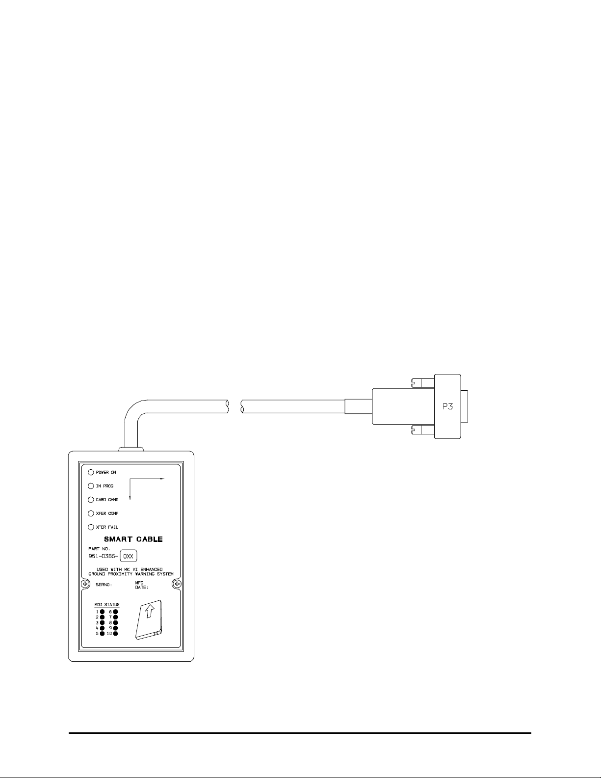
1.5.6 Smart Cabl e (PCMCIA Interface)
The EGPWS Smart Cable (part number 951-0386-001) is a removable PCMCIA card interface. The Smart
Cable is compatible with Honeywell supplied ATA style PCMCIA cards for use with MK VI and MK VIII EGPWS.
The purpose of the Smart Cable in the EGPWS system is for upload of software and databases and also for
download of EGPWS Flight History. The Smart Cable loading operation will closely emulate that of an ARINC
615 Data Loader. (Reference Figure 1-1 MK VI/MK VIII EGPWS SMART CABLE)
FIGURE 1-1 MK VI/MK VIII EGPWS SMART CABLE
Proprietary notice on title page applies
CAGE CODE: 97896 SCALE: NONE SIZE: A DWG NO: 060-4314-150 REV:
SHEET
17
Page 18

Honeywell
MK VI MK VIII EGPWS Installation Design Guide
1.6 Technical C haracteristics
MK VI / VIII EGPWS
TSO Compliance: (MK VI) TSO-C92c, TSO-C151b Class A
(MK VIII) TSO-C92c, TSO-C151b Class A, TSO-C117a
Application for UKCAA Spec 14 is in process
Physical size (HxWxD): 6.20” x 3.04” x 10.30”
Weight: 3.9 pounds maximum
Mounting: Standard 3 inch King Radio rack
Temperature (operational): -55°C to +70°C (F2)
Altitude range: 55,000 feet (F2)
Cooling: No cooling necessary
Shock: No shock mounting required
Power Consumption (28 VDC): 2.5 Amps max
9 watts – no warning
+7 watts – with warning over 8 ohm speaker
+3 watts – with GPS card
+49 watts – with heater blanket on
Configuration Module
TSO Compliance: TSO-C151b
Physical size: 2.68” x 1.51” x 0.32” (fits Positronic connector backshell)
Weight: <1 pound with connector and backshell
Mounting: Mounts to Positronic connector backshell
Temperature (operational): same as MK VI/MK VIII EGPWS
Altitude range: same as MK VI/MK VIII EGPWS
Cooling: No cooling necessary
Shock: No shock mounting required
Power Consumption (5 VDC): from MK VI/MK VIII EGPWS
GPS Antenna Sensor
See Section 1.5.4, ARINC 743A,TSO-C129A and Manufacturer’s specifications.
OAT Sensor
Nominal 500 ohm Temperature probe, resistance at 0°C 500-ohm ± 0.6 ohm, Range -70°C to +60°C (reference
ARINC 575 Section 3.8 or ARINC 706 Section 4.8). See Manufacturer’s specifications.
1.7 Units Supp l ied
1.7.1 MK VI EGP WS
The MK VI EGPWS is available in two versions, with internal GPS card or without. The part number for the units
is as follows:
965-1180-XXX without internal GPS card
965-1190-XXX with Internal GPS card
Proprietary notice on title page applies
CAGE CODE: 97896 SCALE: NONE SIZE: A DWG NO: 060-4314-150 REV:
2
2
SHEET
18
Page 19

Honeywell
MK VI MK VIII EGPWS Installation Design Guide
The MK VI EGPWS is normally shipped with an AMERICAS Terrain database. When ordering a MK VI EGPWS that will be
operating in the ATLANTIC or PACIFIC1 region the specific Terrain database must be specified with the order.
NOTE 1: Terrain Database cards for the ATLANTIC or PACIFIC region are no longer required to be ordered separately.
NOTE 2: -XXX defines Application software version.
1.7.2 MK VIII EGP WS
The MK VIII EGPWS is available in two versions, with internal GPS card or without. The part number for the
units is as follows:
965-1210-XXX without internal GPS card
965-1220-XXX with Internal GPS card
1
1
The MK VIII EGPWS is shipped with a world Terrain database.
NOTE 1: -XXX defines Application software version.
1.7.3 Configurati on Module
The MK VI/MK VIII EGPWS Configuration Module is available in two versions. When ordering the Configuration
Module, order part number 700-1710-020 or part number 700-1710-001. The part number 700-1710-020 is
required for installations with internal GPS.
1.7.4 Smart Cabl e (PCMCIA Interface)
The MK VI/MK VIII EGPWS Smart Cable is available in one version. The Smart Cable is used for Line
Maintenance; Application/Configuration code and Terrain Database uploads and Flight History downloads.
Only one Smart Cable is required for an installation house or operator. When ordering the Smart Cable,
order part number 951-0386-001.
1.8 Installation Kits and Accessories
NOTE: Not all installation kits are immediately available, contact Honeywell Order
Administration (425-885-8719) for availability.
1.8.1 MK VI/MK V III EGPWS Installation Kits
Note: For all parts in the Installation kits the weight of each part is less than 0.25 pounds.
(A) Retrofit classic MK VI GPWS installation
The MK VI/MK VIII EGPWS Installation Kit, P/N 755-7013-011, contains the following parts:
Vendor Name Vendor P/N Description QTY UM Honeywell P/N
Positronic Ind. RD50F1OJVLC-15 P2 connector 1 EA 440-1233-001
Honeywell 700-1710-020 Configuration Module 1 EA 700-1710-020
(B) New EGPWS installation
The MK VI/MK VIII EGPWS Installation Kit, P/N 755-7013-010, contains the following parts:
Vendor Name Vendor P/N Description QTY UM Honeywell P/N
Positronic Ind. DD78F1OJVLC-15 P1 connector, female 1 EA 440-1158-009
Positronic Ind. RD50F1OJVLC-15 P2 connector, female 1 EA 440-1233-001
Honeywell 700-1710-020 Configuration Module 1 EA 700-1710-020
Proprietary notice on title page applies
CAGE CODE: 97896 SCALE: NONE SIZE: A DWG NO: 060-4314-150 REV:
SHEET
19
Page 20

Honeywell
MK VI MK VIII EGPWS Installation Design Guide
Bendix/King 071-04003-0002 Computer Mounting Tray 1 EA 405-0383-001
1.8.2 RS-232 Cab l e
The MK VI/MK VIII EGPWS RS-232 Cable can be ordered using the following part numbers:
NOTE: The RS-232 Cable can be built by the Installer/Operator per the description in Section 4.4.2.
Vendor Name Vendor P/N Description QTY UM Honeywell P/N
Honeywell 704-2617-001 RS-232 Cable 1 EA 704-2617-001
1.8.3 Smart Cabl e
The MK VI/MK VIII EGPWS Smart Cable can be ordered using the following part numbers:
Vendor Name Vendor P/N Description QTY UM Honeywell P/N
Honeywell 951-0386-001 Smart Cable 1 EA 951-0386-001
1.8.4 Terrain Dat abase Cards
The MK VI EGPWS Terrain Database Cards can be ordered using the following part numbers:
Vendor Name Vendor P/N Description QTY UM Honeywell P/N
Honeywell 718-1391-xxx North & South America 1 EA 718-1391-xxx
Honeywell 718-1392-xxx Europe, Africa, Asia 1 EA 718-1392-xxx
Honeywell 718-1393-xxx Asia, Australia, Pacific 1 EA 718-1393-xxx
Honeywell 402-6075-xxx Label, TDB Front Panel 1 EA 402-6075-xxx
1.8.5 Flight Histo ry Card
The MK VI/MK VIII EGPWS Flight History Card can be ordered using the following part numbers:
Vendor Name Vendor P/N Description QTY UM Honeywell P/N
Honeywell
Honeywell
300-1151-006
718-1593-001
1
2
Flight History Download
Flight History Download
1
1
EAEA300-1151-006
718-1593-001
Note 1: Unprogrammed (blank) 32 Mb card ATA PCMCIA card.
Note 2: Programmed 32 Mb card ATA PCMCIA card.
1.9 Accessorie s not Supplied
1.9.1 ARINC 453 Terrain Display wiring
The Terrain display wiring (ARINC 453) must meet the display manufacturer’s specifications including
termination method. ARINC 453 bus wiring must meet the following requirements:
• Cable length must be less than 300 feet (91.4 meters).
• Wire to wire capacitance must not exceed 50 pF/foot.
• Shielded twisted pair with not less than one twist per inch.
• Impedance of 78 ohms ±10% at 1 MHz (ARINC 708 WXR).
• Impedance of 70 ohms ±10% at 1 MHz (ARINC 453 bus).
Vendor Name Vendor P/N Description QTY UM
Pic Wire&Cable D620224 ARINC 453 cable A/R EA
1
Proprietary notice on title page applies
CAGE CODE: 97896 SCALE: NONE SIZE: A DWG NO: 060-4314-150 REV:
SHEET
20
Page 21

Honeywell
MK VI MK VIII EGPWS Installation Design Guide
Pic Wire&Cable D5102QX Hi Temp Quadraxial A/R EA
Pic Wire&Cable D771553 MIL-STD 1553 Data Bus A/R EA
ECS
ECS
4122021
312402
ARINC 453 cable (2 shields)
ARINC 453 cable (3 shields)
A/R
A/REAEA
Emteq D70-022402T-01 ARINC 453 cable A/R EA
M17/176-00002
M83536/6-022M
M12883/44-01
Military Specification
Relay, 4PDT
(Note 1)
Relay, Socket (Note 1)
A/R
A/R
A/R
EA
EA
EA
Note 1: Recommended in EFS 40/50 Installation Manual.
1.9.2 GPS Anten n a & Cable
The GPS Antenna & cable can be ordered from their manufacturers using the following part numbers:
Vendor Name Vendor P/N Description QTY UM Honeywell P/N
Bendix/King 071-01553-0200 KA 92 GPS Antenna (26dB) 1 EA 300-1147-001
Comant CI 405-2 KA 92 GPS Antenna (26dB) 1 EA 300-1147-001
Bendix/King 050-03318-0000 Antenna Installation Kit OPT EA 405-0432-001
Sensor Systems
Sensor Systems
Sensor Systems
Thermax M17/128-RG400 Coax Cable, RG400/U A/R EA
PIC S14293 Coax Cable A/R EA
PIC S44191 Coax Cable A/R EA
ECS 311901 Coax Cable A/R EA
ECS 311601 Coax Cable A/R EA
ECS 311201 Coax Cable A/R EA
Amp 225554-6 TNC Angle Plug, Male 1 EA 440-1239-001
Amphenol 79075 TNC Angle Plug, Male 1 EA 440-1239-001
S67-1575-38 S67 GPS Antenna (29dB) 1 EA
S67-1575-52 S67 GPS Antenna (26dB) 1 EA
S67-1575-133 S67 GPS Antenna (33dB) 1 EA
Coax Cable, RG-142B/U A/R EA
NOTE: If a satellite communication system is installed in the aircraft, or the GPS cable run is in the vicinity of a
VHF transceiver and/or cable, DO NOT USE R/G 142 or R/G 400 cable.
1.9.3 Circuit Brea ker
The Circuit Breaker needs to be a 3 Amp delayed action circuit breaker.
Vendor Name Vendor P/N Description QTY UM
Klixon (T.I.) 7277-2-3 3 Amp Circuit Breaker,
EGPWS power +28
Klixon (T.I.) 7277-2-1 1 Amp Circuit Breaker, lamp
power +28
Proprietary notice on title page applies
CAGE CODE: 97896 SCALE: NONE SIZE: A DWG NO: 060-4314-150 REV:
1EA
1EA
SHEET
21
Page 22

Honeywell
MK VI MK VIII EGPWS Installation Design Guide
1.9.4 Annunciato r s & Switch/Annunciators
The devices shown below are West Coast Specialties and Staco switch/annunciators and are representative of
those used in some installations. However, there are other comparable devices on the market that may be
substituted at the installer/customers choice. The installer/customer is cautioned to verify regulatory
approval of the annunciation devices installed. See Appendix D for Vendors.
A. GPWS (P/TEST); BELOW G/S (P/CANCEL) switch/annunciator assemblies
The ‘GPWS’ annunciator provides visual indication of an EGPWS warning or alert. The GPWS annunciator
also has a momentary switch that is used to manually initiate EGPWS Self Test. Two GPWS annunciators
are required for each aircraft, one in the direct view of each pilot. If the Lamp Format 2 option is selected
(see 3.15.2.1), this switch/annunciator will be labeled ‘PULL UP’ and annunciated in red.
The ‘BELOW G/S’ annunciator provides visual indication of an EGPWS glideslope caution. The BELOW
G/S annunciator also has a momentary switch that is used to manually inhibit EGPWS Mode 5 glideslope
alerts. Two BELOW G/S annunciators are required for each aircraft, one in the direct view of each pilot. If
the Lamp Format 2 option is selected (see 3.15.2.1), this switch/annunciator will be labeled ‘GPWS’ and
annunciated in amber.
Vendor Name Vendor P/N Description QTY UM
West Coast Spec.
West Coast Spec.
West Coast Spec.
West Coast Spec.
STACO
STACO
STACO
STACO
(1) GPWS – BELOW G/S – GPWS FLAP OVRD – G/S CANCLD
90-81401-001 GPWS BELOW G/S 2 EA
90-81401-003 GPWS BELOW G/S ALT EA
90-81401-008 GPWS BELOW G/S (1) ALT EA
90-81401-009 GPWS BELOW G/S (1) ALT EA
61406-003 GPWS G/S CANCEL ALT EA
61406-004 PULL UP GPWS TEST ALT EA
61406-005 GPWS GPWS TEST ALT EA
61406-006 BELOW G/S G/S CANCEL ALT EA
B. GPWS FLAP OVRD; GPWS INOP; G/S CANCLD switch/annunciator assemblies
The ‘GPWS FLAP OVRD’ annunciator provides visual indication that the EGPWS Flap Override function is
activated. The GPWS FLAP OVRD annunciator also has a momentary switch that is used to manually activate
the Flap Override function.
The ‘GPWS INOP’ annunciator provides visual indication that the EGPWS’ GPWS modes have been disabled
or do not function because of an external or internal fault.
The ‘G/S CANCLD’ annunciator provides visual indication that the EGPWS Mode 5 function is inhibited.
Vendor Name Vendor P/N Description QTY UM
West Coast Spec.
West Coast Spec.
West Coast Spec.
90-81401-008 (1) 1 EA
90-81401-009 (2) 1 EA
90-81401-010 (3) 1 EA
Proprietary notice on title page applies
CAGE CODE: 97896 SCALE: NONE SIZE: A DWG NO: 060-4314-150 REV:
SHEET
22
Page 23

Honeywell
MK VI MK VIII EGPWS Installation Design Guide
West Coast Spec.
West Coast Spec.
STACO 61406-007 GPWS FLAP
(1) GPWS – BELOW G/S – GPWS FLAP OVRD – G/S CANCLD
(2) GPWS – BELOW G/S – GPWS FLAP OVRD – GPWS INOP
(3) GPWS FLAP OVRD – G/S CANCLD
(4) GPWS INOP – G/S CANCLD – GPWS FLAP OVRD
(5) GPWS FLAP OVRD – GPWS INOP
90-81401-011 (4) 1 EA
90-81401-012 (5) 1 EA
OVERRIDE 1EA
C. TERR DISPLAY; TERR INHIBIT; GPWS FAIL / TERR FAIL switch/annunciator assemblies
The ‘TERR DISPLAY’ annunciator provides visual indication that the EGPWS Terrain Display has been selected
for the associated display. The TERR DISPLAY annunciator also has a momentary switch that is used to
manually select the Terrain Display.
The ‘TERR INHIBIT’ annunciator provides visual indication that the EGPWS Terrain functions have been
inhibited. The TERR INHIBIT annunciator also has a alternate action switch that is used to manually inhibit the
Terrain functions.
The ‘GPWS FAIL / TERR FAIL’ annunciator provides visual indication that the EGPWS GPWS modes or TA&D
and TCF modes have a disabled function.
Vendor Name Vendor P/N Description QTY UM
STACO 61406-001 TERRAIN DISPLAY ON 1 EA
STACO 61406-002 TERR INHIBIT ON 1 EA
STACO
61406-011
GPWS FAIL TERRAIN FAIL
1EA
1.9.5 Cockpit Sp e akers
The MK VI / MK VIII EGPWS can interface to an 8 ohm audio speaker for cockpit annunciation of aural alerts.
Vendor Name Vendor P/N Description QTY UM
Quam 30A05Z8 Audio Speaker 1 EA
Utah SP-3A Audio Speaker 1 EA
1.9.6 Temperatur e Probes
The MK VI / MK VIII EGPWS may be optionally interfaced to a dedicated 500-ohm temperature probe meeting
the specifications of ARINC 575 Section 3.8. The installer may want to discuss availability of a dual-element
probe compatible with the EGPWS and with other systems on the aircraft with the manufacturers.
Vendor Name Vendor P/N Description QTY UM
CIC
Norwich
Norwich
Rosemount 102CT2CB 500-ohm 1 EA
Rosemount 102AU1AF Single element, heated 1 EA
Rosemount 102AU1AG Dual element, heated 1 EA
05257
103-00157-3
103-00034
Single element, unheated
Single element, unheated
Dual element, unheated
1
1
1
EA
EA
EA
Proprietary notice on title page applies
CAGE CODE: 97896 SCALE: NONE SIZE: A DWG NO: 060-4314-150 REV:
SHEET
23
Page 24

Honeywell
MK VI MK VIII EGPWS Installation Design Guide
Rosemount 102EH2BH Dual element, heated 1 EA
Rosemount 102EH2EB Dual element, heated 1 EA
Rosemount 102JE2FG Triple element, heated 1 EA
Rosemount 129H-500 Single element, unheated 1 EA
Rosemount 129G-500 Dual element, unheated 1 EA
1.10 Tools Requ i red
1.10.1 Crimping T ool - P1, P2, P3
Description UM QTY Vendor Name & Part Number
Hand Crimping Tool EA 1 Positronic Ind. 9507
Hand Crimping Tool EA 1 Daniels AFM8
Hand Crimping Tool EA 1 Military M22520/2-1
Hand Crimping Tool EA 1 Astro 61517
1.10.2 Contact Po sitioner - P1, P2, P3
Description UM QTY Vendor Name & Part Number
Contact Positioner, Socket P1 EA 1 Positronic Ind. 9502-3
Contact Positioner, Socket P1 EA 1 Daniels K41 (for 22 to 28 AWG)
Contact Positioner, Socket P1 EA 1 Military M22520/2-06
Contact Positioner, Socket P2 EA 1 Positronic Ind. 9502-5
Contact Positioner, Socket P2 EA 1 Daniels K13-1 (20-24 AWG)
Contact Positioner, Socket P2 EA 1 Military M22520/2-08
Contact Positioner, Pin P3 EA 1 Positronics 9502-4
Contact Positioner, Pin P3 EA 1 Daniles K42 (22-28 AWG)
Contact Positioner, Pin P3 EA 1 Military M22520/2-09
1.10.3 Insertion/R emoval Tool - P1, P2, P3
Description UM QTY Vendor Name & Part Number
Removal Tool P1, P3 EA 1 Daniels DRK 95-22M
Removal Tool P1, P3 EA 1 Military M81969/8-02
Removal Tool P2 EA 1 Daniels DRK145
Insertion Tool P1, P3 EA 1 Daniels DAK 95-22M
Insertion Tool P1, P3 EA 1 Military M81969/8-01
Insertion Tool P2 EA 1 Daniels DAK145
Insertion/Removal Tool P1, P3 EA 1 Military M81969/1-04
Insertion/Removal Tool P2 EA 1 Military M81969/1-02
Proprietary notice on title page applies
CAGE CODE: 97896 SCALE: NONE SIZE: A DWG NO: 060-4314-150 REV:
SHEET
24
Page 25

Honeywell
MK VI MK VIII EGPWS Installation Design Guide
1.10.4 Spare Conn e ctors and Contacts - P1, P2, P3
P/N Description UM QTY Vendor Name & Part Number
440-1223-002 15 pin male with hood EA 1 Positronic Ind. DD15M10YOC-15
1
440-1223-003
440-1223-004
400-5163-002
15 pin female EA 1 Positronic Ind. DD15F10OOC-15
1
15 pin male EA 1 Positronic Ind. DD15M10OOC-15
1
15 pin clamp kit EA 1 AMP 745854-3
male contacts for 15 pin 22-30 AWG EA 1 Positronic Ind. MC8022D
male contacts for 15 pin 22-30 AWG EA 1 M39029/58-360
female contacts for 50 pin 20-24 AWG EA 1 Positronic Ind. FC6020D
female contacts for 50 pin 20-24 AWG EA 1 M39029/63-368
female contacts for 78 pin 22-30 AWG EA 1 Positronic Ind. FC8022D
female contacts for 78 pin 22-30 AWG EA 1 M39029/57-354
1
These parts are available in EGPWS kit PN 755-7013-090.
1.11 License Re q uirements
There are no Radio license requirements for the MK VI/MK VIII EGPWS
Proprietary notice on title page applies
CAGE CODE: 97896 SCALE: NONE SIZE: A DWG NO: 060-4314-150 REV:
SHEET
25
Page 26

Honeywell
MK VI MK VIII EGPWS Installation Design Guide
THIS PAGE INTENTIONALLY LEFT BLANK
Proprietary notice on title page applies
CAGE CODE: 97896 SCALE: NONE SIZE: A DWG NO: 060-4314-150 REV:
SHEET
26
Page 27

Honeywell
MK VI MK VIII EGPWS Installation Design Guide
SECTION II
INSTALLATION
Proprietary notice on title page applies
CAGE CODE: 97896 SCALE: NONE SIZE: A DWG NO: 060-4314-150 REV:
SHEET
27
Page 28

Honeywell
MK VI MK VIII EGPWS Installation Design Guide
SECTION II - INSTALLATION
SECTION II - INSTALLATION........................................................................................................................................ 29
2.1 I
NTRODUCTION.............................................................................................................................................................. 29
2.2 U
NPACKING AND INSPECTING THE EQUIPMENT ............................................................................................................. 29
2.3 E
QUIPMENT INSTALLATION........................................................................................................................................... 29
2.3.1 General.................................................................................................................................................................. 29
2.3.2 MK VI/MK VIII Computer Location...................................................................................................................... 29
2.3.3 MK VI/ MK VIII Computer Installation................................................................................................................. 30
2.3.4 Configuration Module Location............................................................................................................................ 31
2.3.5 Configuration Module Installation........................................................................................................................ 31
2.3.6 GPS Antenna location ........................................................................................................................................... 40
2.3.7 GPS Antenna Installation...................................................................................................................................... 40
2.3.8 OAT Sensor Location ............................................................................................................................................ 40
2.3.9 OAT Sensor Installation ........................................................................................................................................ 40
2.3.10 Cockpit Lights...................................................................................................................................................... 40
2.3.10.1 Description........................................................................................................................................................................41
2.3.10.2 Location ............................................................................................................................................................................42
Proprietary notice on title page applies
CAGE CODE: 97896 SCALE: NONE SIZE: A DWG NO: 060-4314-150 REV:
SHEET
28
Page 29

Honeywell
MK VI MK VIII EGPWS Installation Design Guide
SECTION II - INSTALLATION
2.1 Introductio n
This section contains suggestions and factors to consider before installing the Enhanced Ground Proximity
Warning System. Close adherence to these suggestions will assure satisfactory performance from the
equipment.
NOTE
The conditions and tests performed on this article are minimum performance standards. It is
the responsibility of those desiring to install this article either on or within a specific type or
class of aircraft to determine that the aircraft installation conditions are within these
performance standards. The article may be installed only if further evaluation by the
applicant documents an acceptable installation and is approved by the airworthiness
authority.
2.2 Unpacking a nd Inspecting the Equipment
Exercise extreme caution when unpacking equipment. Perform a visual inspection of the unit for evidence of
damage incurred during shipment. If a damage claim must be filed, save the shipping container and all packing
materials to substantiate your claim. The claim should be filed as soon as possible. The shipping container and
all packing materials should be retained in the event that storage or reshipment of the equipment is necessary.
2.3 Equipment Installation
2.3.1 General
The following paragraphs contain information pertaining to the installation of the MK VI and MK VIII EGPWS,
including instructions concerning the location and mounting of the equipment. The equipment should be
installed in the aircraft in a manner consistent with acceptable workmanship and engineering practices, and in
accordance with the instructions set forth in this publication. To ensure the system has been properly and safely
installed in the aircraft, the installer should make a thorough visual inspection and conduct an overall operational
check of the system, on the ground, prior to flight.
CAUTION
AFTER INSTALLATION OF THE CABLING AND BEFORE INSTALLATION OF THE
EQUIPMENT, A CHECK SHOULD BE MADE WITH THE AIRCRAFT PRIMARY POWER
SUPPLIED TO THE MOUNTING CONNECTOR, TO ENSURE THAT POWER IS APPLIED
ONLY TO THE PINS SPECIFIED IN THE INTERWIRING DIAGRAMS IN SECTION III.
2.3.2 MK VI/MK V III Computer Location
Care should be exercised to avoid mounting components near equipment operating with high pulse current or
high power outputs such as radar and satellite communications equipment. In general, the equipment should be
Proprietary notice on title page applies
CAGE CODE: 97896 SCALE: NONE SIZE: A DWG NO: 060-4314-150 REV:
SHEET
29
Page 30

Honeywell
MK VI MK VIII EGPWS Installation Design Guide
installed in a location convenient for operation, inspection, and maintenance, and in an area free from excessive
vibration, heat, and noise generating sources.
The MK VI and MK VIII EGPWS have an internal heater blanket therefore they can be mounted outside the
heated area of the aircraft. The computers have been qualified for operation up to 50,000 feet and -55°C using
the heater blanket.
All mechanical installation drawings, connector assembly diagrams, interwiring diagrams, and connector pin
assignment tables referenced in this section are located at the end of Section II of this manual. Determine the
mounting location for the system components following the guidelines below.
Prior to installing any equipment, make a continuity check of all wires and cables associated with the system.
Then apply power and check for proper voltages at system connectors, and then remove power before
completing the installation.
To allow for inspection or repair of the wiring of the connector assembly itself, sufficient lead length should be
left so that EGPWS may be moved several inches. A bend should be made in the harness to allow water
droplets that might form on the harness due to condensation, to drip off at the bend and not collect in the
connector.
NOTE
For retrofit installations of classic MK VI GPWS and installing a EGPWS with internal GPS,
the connector backshell of the classic MK VI P1 connector will interfere with the GPS
antenna connector on the front of the EGPWS. The connector backshells chosen for the
EGPWS kits now extends straight out and does not interfere with the GPS antenna
connector.
The length of cables from the EGPWS connectors to other system units is not generally critical because unit
interfaces are designed with high impedance inputs, low impedance outputs, and low noise susceptibility
characteristics. The exception is the wires from the EGPWS Configuration Module, which was designed to be a
part of the EGPWS connector backshell because of the requirement for short lead length. Follow aircraft
manufacturer’s, sub-system manufacturer’s or ARINC specifications for shield grounding.
2.3.3 MK VI/ MK VIII Computer Installation
The MK VI and MK VIII EGPWS installation will conform to standards designated by the customer, installing
agency, and existing conditions as to the unit location and type of installation. However, the following
suggestions will assure a more satisfactory performance from the equipment.
A. Plan a location on the aircraft so that the EGPWS is accessible for front panel maintenance controls. Check
to be sure that there is adequate space in the front of the computer for connectors and cabling.
B. Refer to Figure 2-2 and 2-3 for outline dimensions of the computer and mounting tray.
Proprietary notice on title page applies
CAGE CODE: 97896 SCALE: NONE SIZE: A DWG NO: 060-4314-150 REV:
SHEET
30
Page 31

Honeywell
MK VI MK VIII EGPWS Installation Design Guide
C. Mount the EGPWS mounting tray in the aircraft radio rack or other location using the four screw mounting
holes. Match drill the mounting holes using the Mounting Tray as a template.
D. Ensure that the mounting tray is electrically bonded (less than 10 milli-ohm to aircraft ground).
E. Slide the EGPWS unit in the mounting tray, and secure it using the Hold Down latch.
F. (After Continuity and Power check) Attach the cable harness to the front panel connectors and lock
connectors using the slide lock of the P1 & P2 connectors. The EGPWS should be wired according to the
interconnect diagrams in Section III, of this manual.
2.3.4 Configurati on Module Location
The aircraft configuration is programmed into the EGPWS Configuration Module installed in the aircraft wiring.
The Configuration Module is identified as Honeywell part number 700-1710-020 (optional part number 700-
1710-001). The Configuration Module is installed as one side of the P2 (50 pin) mating connector backshell and
contains electrically reprogrammable memory for configuration storage. The Configuration Module when
installed is wired directly to the appropriate pins in the P2 connector.
2.3.5 Configurati on Module Installation
The purpose of this procedure is to give an assembly sequence for assembly of the Configuration Module with
the P2 connector and backshell.
A. The P2 connector, Honeywell part number 440-1233-001, vendor part number RD50F1OJVLC-15, when
ordered comes with 50 contacts and a plastic backshell (hood).
B. The Configuration Module will replace the Backshell Plate. The Backshell Plate can be discarded.
C. Wire the Configuration Module to the P2 connector using contacts provided with the connector. Wire per the
following wire list:
Wire Color P2 pin #
Violet P2-17
Blue P2-16
Orange P2-33
Black P2-50
White P2-49
Red P2-32
Proprietary notice on title page applies
CAGE CODE: 97896 SCALE: NONE SIZE: A DWG NO: 060-4314-150 REV:
SHEET
31
Page 32

Honeywell
MK VI MK VIII EGPWS Installation Design Guide
D. Position Slide Lock and Spring Clip onto connector.
E. Install Backshell Housing onto connector. The Ground wire (used for ESD discharge) is terminated with
shielded pigtails inside the backshell to the P2 connector.
F. Organize and dress wire exiting from the backshell, route Configuration Module wires in a coil. Install Cable
Clamp, do not tighten Cable Clamp screws.
G. Secure the Configuration Module to the connector using screws provided. Tighten Cable Clamp screws as
required.
CONFIGURATION MODULE ASSEMBLY
REQUIRED: Two items as follows:
1.0 Connector (P2) Positronic Ind. RD50F10JVLC-15 *
2.0 Configuration Module Honeywell 700-1710-020
* This item may be available from Honeywell under Part No. (440-1233-001)
ITEM 2 DESCRIPTION:
Connector P2 (Positronic Ind. PN RD50F10JVLC-15) is a packaged kit consisting of the following parts:
1.1 Connector, 50 socket D-Sub Qty - 1
1.2 Contacts, size 20 crimp Qty - 50
1.3 Backshell housing Qty - 1
1.4 Backshell plate Qty - 1
1.5 Screws, Phillips CSK Qty - 2
1.6 Spring Clip Qty - 1
1.7 Slide Lock Qty - 1
1.8 Screws, Slotted Qty - 2
1.9 Cable Clamp Qty - 1
Proprietary notice on title page applies
CAGE CODE: 97896 SCALE: NONE SIZE: A DWG NO: 060-4314-150 REV:
SHEET
32
Page 33

Honeywell
MK VI MK VIII EGPWS Installation Design Guide
INSTALLATION ASSEMBLY SEQUENCE
STEP 1 Install all MK VI/MK VIII system aircraft wiring to this connector using items 1.2 (Crimp
Contacts) and item 1.1 (Connector). See figure 2.1-1 below.
FIGURE 2.1-1 MK VI/MK VIII EGPWS CONFIGURATION MODULE
Proprietary notice on title page applies
CAGE CODE: 97896 SCALE: NONE SIZE: A DWG NO: 060-4314-150 REV:
SHEET
33
Page 34

Honeywell
MK VI MK VIII EGPWS Installation Design Guide
STEP 2 Wire item 2.0 (Configuration Module). This part will replace item 1.4 (Backshell plate). Install
the pre-crimped colored wires into item 1.1 (Connector) as shown in figure 2.1-2 below.
FIGURE 2.1-2 MK VI/MK VIII EGPWS CONFIGURATION MODULE
Proprietary notice on title page applies
CAGE CODE: 97896 SCALE: NONE SIZE: A DWG NO: 060-4314-150 REV:
SHEET
34
Page 35

Honeywell
MK VI MK VIII EGPWS Installation Design Guide
STEP 3 Position item 1.7 (Slide lock) onto wired connector as shown in figure 2.1-3 below:
FIGURE 2.1-3 MK VI/MK VIII EGPWS CONFIGURATION MODULE
Proprietary notice on title page applies
CAGE CODE: 97896 SCALE: NONE SIZE: A DWG NO: 060-4314-150 REV:
SHEET
35
Page 36

Honeywell
MK VI MK VIII EGPWS Installation Design Guide
STEP 4 Install item 1.3 (Backshell Housing) onto connector using item 1.8 (Screws) as shown in figure
2.1-4 below:
Ground Wire (used for electrostatic discharge {ESD} protection) is terminated with shielded
pigtails of wires at this connector.
FIGURE 2.1-4 MK VI/MK VIII EGPWS CONFIGURATION MODULE
Proprietary notice on title page applies
CAGE CODE: 97896 SCALE: NONE SIZE: A DWG NO: 060-4314-150 REV:
SHEET
36
Page 37

Honeywell
MK VI MK VIII EGPWS Installation Design Guide
STEP 5 Install item 1.6 (Spring Clip) as shown figure 2.1-5 below:
FIGURE 2.1-5 MK VI/MK VIII EGPWS CONFIGURATION MODULE
Proprietary notice on title page applies
CAGE CODE: 97896 SCALE: NONE SIZE: A DWG NO: 060-4314-150 REV:
SHEET
37
Page 38

Honeywell
MK VI MK VIII EGPWS Installation Design Guide
STEP 6 Organize and dress wiring exiting from backshell. Route Configuration Module wires exiting
from connector, then coil as shown in figure 2.1-6 below. Install item 1.9 (Cable Clamp) as
shown. Do not tighten screws yet.
FIGURE 2.1-6 MK VI/MK VIII EGPWS CONFIGURATION MODULE
Proprietary notice on title page applies
CAGE CODE: 97896 SCALE: NONE SIZE: A DWG NO: 060-4314-150 REV:
SHEET
38
Page 39

Honeywell
MK VI MK VIII EGPWS Installation Design Guide
STEP 7 Secure Configuration Module to connector assembly using item 1.5 (Screws) as shown in figure
2.1-7 below. Tighten Cable Clamp screws as required.
FIGURE 2.1-7 MK VI/MK VIII EGPWS CONFIGURATION MODULE
Proprietary notice on title page applies
CAGE CODE: 97896 SCALE: NONE SIZE: A DWG NO: 060-4314-150 REV:
SHEET
39
Page 40

Honeywell
MK VI MK VIII EGPWS Installation Design Guide
2.3.6 GPS Anten n a location
The GPS antenna should be mounted on top of the fuselage in the centerline of the aircraft. Avoid mounting the
antenna near any projections, the propeller, and the T-tail of the aircraft, where shadows could occur. It is
recommended that there be a separation of at least 3 feet between the GPS antenna and any VHF Comm
antenna on the aircraft. The GPS antenna baseplate must be level within ± 5° in both axis when the aircraft is
level (level is defined as the aircraft attitude required when weighing the aircraft for weight and balance). If the
GPS antenna is tilted more than 5° or is mounted close to other objects that shadow it, loss of some of the
satellites will occur and system performance degraded. See manufacturer for specifications of GPS antennas.
Some GPS Antenna cable and connector information, including vendor information, is listed below.
Cable Length Cable Part
Number (VPN)
0 to 40 ft RG142B/U
RG400/U
0 to 80 ft ECS 311601 TED Mfg. 5-10-307 TED Mfg. 5-10-307 8.0
0 to 100 ft ECS 311201 TED Mfg. 5-10-306 TED Mfg. 5-10-306 8.0
100 to 165 ft Contact TED, ECS or PIC for complete cable/connector assembly
* Maximum Allowable Loss (dB) @ 1575 MHz for cable and connector using nominal 26.5 dB gain.
TED Manufacturing Corp.
11415 Johnson Drive
Shawnee, Kansas 66203
Tel: (913) 631-6211
EGPWS TNC
Connector (VPN)
TED Mfg. 5-10-30 TED Mfg. 5-30-102-1 8.0
Electronic Cable Specialists (ECS)
5300 W. Franklin drive
Franklin, Wisconsin 53132
Tel: (800) 327-9473
Antenna TNC
Connector (VPN)
PIC Wire & Cable
N63 W 22619 Main Street
Sussex, Wisconsin 53089
Tel: (800) 742-3191
Max Loss*
2.3.7 GPS Anten n a Installation
Refer to manufacturer’s procedures or applicable STC documentation.
2.3.8 OAT Senso r Location
The OAT sensor should be mounted on the underside (belly) of the aircraft or other convenient location meeting
the following conditions. Avoid mounting the sensor where it can be affected by direct sunlight, or exhaust gases
from engines or heaters. The probe tip should extend beyond the aircraft boundary layer into the turbulent
airflow. See manufacturer for specifications.
2.3.9 OAT Senso r Installation
Refer to manufacturer’s procedures or applicable STC documentation.
2.3.10 Cockpit Lig hts
This section provides information for selecting, locating and mounting of the MK VI and MK VIII EGPWS Cockpit
lights. NOTE: The nomenclature given for each lamp is an example only. Other manufacturers use
nomenclature that is also acceptable.
Proprietary notice on title page applies
CAGE CODE: 97896 SCALE: NONE SIZE: A DWG NO: 060-4314-150 REV:
SHEET
40
Page 41

Honeywell
MK VI MK VIII EGPWS Installation Design Guide
NOTE: All lights
1. Refer to Honeywell Product Specification 965-1176-601 for additional information and for electrical
loads specification.
2. All lights are +28 VDC, dual bulb, sun light readable, non-flashing.
3. In the “OFF” condition, all lights have dark background with visible nomenclature for action.
4. If desired the lights may be put on a “dimmer” circuit for night operation.
2.3.10.1 Description
EGPWS alert/warning (Lamp Format 1) GPWS P/TEST
This assembly is illuminated with red background and activated during any Mode 1 through Mode 4, and Terrain
Awareness alert or warning. This assembly also includes a momentary switch that will activate EGPWS Self
Test.
EGPWS warning (Lamp Format 2) PULLUP P/TEST
This assembly is illuminated with red background and activated during any Mode 1, Mode 2, or Terrain
Awareness PullUp warning. This assembly also includes a momentary switch that will activate EGPWS Self
Test.
GLIDESLOPE alert (Lamp Format 1) BELOW G/S P/CANCEL
This assembly is illuminated with amber background and activated during any Mode 5 alert. This assembly also
includes a momentary switch that will de-activate (cancel) EGPWS Mode 5 alerts during backcourse or low
altitude approaches.
EGPWS caution (Lamp Format 2) GPWS G/S CANCEL
This assembly is illuminated with amber background and activated during any EGPWS alert (non-Pullup). This
assembly also includes a momentary switch that will de-activate (cancel) EGPWS Mode 5 alerts during
backcourse or low altitude approaches.
Glideslope Canceled G/S CANCLD (optional but recommended)
This assembly is illuminated with white, blue or amber background and activated after the flight crew has
initiated the manual cancel of Mode 5 by pressing the BELOW G/S – P/CANCEL light/switch described above.
EGPWS Flap Override GPWS FLAP OVRD (optional but recommended)
This guarded light/switch assembly is illuminated with blue background and activated after the flight crew has
initiated the manual selection of the GPWS Flap Override feature. This assembly also includes a momentary
switch that will activate GPWS Flap Override. Note: the light color may also be white background with black
legend or black background with white legend. Colors are per FAR 23.1322.
GPWS system validity GPWS INOP
This assembly is illuminated with amber background and activated during any detected partial or total failure of
the GPWS modes 1-5.
TERRAIN select TERR DISPLAY ON
Proprietary notice on title page applies
CAGE CODE: 97896 SCALE: NONE SIZE: A DWG NO: 060-4314-150 REV:
SHEET
41
Page 42

Honeywell
MK VI MK VIII EGPWS Installation Design Guide
This assembly is illuminated with white background and activated after the flight crew has initiated the manual
selection of the EGPWS terrain display for the associated cockpit display. This assembly also includes a
momentary switch that will activate EGPWS Terrain display feature.
TERRAIN inhibit TERR INHIBIT ON
This assembly is illuminated with amber background and activated after the flight crew has initiated the manual
inhibit of the EGPWS Terrain Awareness & display and Terrain Clearance Floor functions during an approach to
an airport not in the EGPWS Terrain/Runway database. This assembly also includes a alternate action switch
that will inhibit EGPWS TA&D and TCF functions.
TERRAIN system validity TERR FAIL
This assembly is illuminated with amber background and activated during any detected partial or total failure of
the TA&D or TCF functions.
2.3.10.2 Location
Cockpit layout, size and operator’s preference will determine if only one set of lights is used (i.e., mounted in the
center), or if dual sets of lights are used (one set on each side), or a combination thereof is desired. For a typical
example of cockpit light locations refer to Figure 2-3. For panel cutouts and assembly options see the
manufacturer’s specifications. The following are recommended locations:
GPWS & BELOW G/S or PULLUP & GPWS
These lights should be located together and in the flight crew’s “primary field of view”. This would include either
the instrument panel or the edge of the glareshield.
GPWS FLAP OVRD -Optional-
This light should be located in the flight crew’s “field of view” and within reach of both crew members. This
light/switch may be located in an assembly with the GPWS and BELOW G/S lights and/or other EGPWS
annunciators.
GPWS CANCLD -Optional-
If used, this light should be located within at least one crew member’s “field of view”.
GPWS INOP
This light should be located within at least one crew member’s “field of view” or with other system INOP lights of
similar importance. It is recommended that this light not be located in the flight crew’s “primary field of view”. The
reason being that in the event of a GPWS system failure at the beginning of a flight, this light will remain “ON”
until the problem is fixed. This light may be combined with the TERR FAIL light.
TERR DISPLAY ON
This light should be located near the associated cockpit display, in the flight crew’s “field of view” and within
reach of one or both crew members. This light/switch may be located in an assembly with the TERR INHIBIT
light(s) and/or other EGPWS annunciators.
TERR INHIBIT ON
This light should be located in the flight crew’s “field of view” and within reach of both crew members. This
light/switch may be located in an assembly with the TERR DISPLAY light(s) and/or other EGPWS annunciators.
Proprietary notice on title page applies
CAGE CODE: 97896 SCALE: NONE SIZE: A DWG NO: 060-4314-150 REV:
SHEET
42
Page 43

Honeywell
MK VI MK VIII EGPWS Installation Design Guide
TERR FAIL
This light should be located within at least one crew member’s “field of view” or with other system INOP lights of
similar importance. Note: Annunciators are available with split legend GPWS FAIL / TERR FAIL in one
assembly. It is recommended that this light not be located in the flight crew’s “primary field of view”. The reason
being that in the event of a GPWS system failure at the beginning of a flight, this light will remain “ON” until the
problem is fixed.
PULLUP
GPWS
TERRONTERR
INHB
TERR
FAIL
PULLUP
The above picture is an example of lamp location and
does not restrict lamp location or format
Figure 2.3
GPWS
Proprietary notice on title page applies
CAGE CODE: 97896 SCALE: NONE SIZE: A DWG NO: 060-4314-150 REV:
SHEET
43
Page 44

Honeywell
MK VI MK VIII EGPWS Installation Design Guide
FIGURE 2-2 MK VI/MK VIII EGPWS OUTLINE
Proprietary notice on title page applies
CAGE CODE: 97896 SCALE: NONE SIZE: A DWG NO: 060-4314-150 REV:
SHEET
44
Page 45

Honeywell
MK VI MK VIII EGPWS Installation Design Guide
FIGURE 2-3 MK VI/MK VIII EGPWS MOUNTING TRAY
Proprietary notice on title page applies
CAGE CODE: 97896 SCALE: NONE SIZE: A DWG NO: 060-4314-150 REV:
SHEET
45
Page 46

Honeywell
MK VI MK VIII EGPWS Installation Design Guide
THIS PAGE INTENTIONALLY LEFT BLANK
Proprietary notice on title page applies
CAGE CODE: 97896 SCALE: NONE SIZE: A DWG NO: 060-4314-150 REV:
SHEET
46
Page 47

Honeywell
MK VI MK VIII EGPWS Installation Design Guide
SECTION III
SYSTEM PLANNING
Proprietary notice on title page applies
CAGE CODE: 97896 SCALE: NONE SIZE: A DWG NO: 060-4314-150 REV:
SHEET
47
Page 48

Honeywell
MK VI MK VIII EGPWS Installation Design Guide
SECTION III – SYSTEM PLANNING
SECTION III – SYSTEM PLANNING..............................................................................................................................51
3.1 I
NTRODUCTION.............................................................................................................................................................. 51
3.2 S
YSTEM WIRING/ ELECTRICAL INTERFACES ................................................................................................................. 51
3.2.1 Primary Power Input.............................................................................................................................................51
3.2.2 Chassis Ground.....................................................................................................................................................52
3.2.3 GPS Antenna .........................................................................................................................................................52
3.2.4 Analog and Digital Inputs .....................................................................................................................................52
3.2.5 Discrete Inputs ......................................................................................................................................................52
3.2.6 Serial Outputs........................................................................................................................................................52
3.2.7 Audio Output .........................................................................................................................................................53
3.2.8 Discrete Outputs....................................................................................................................................................53
3.2.9 Configuration Module ...........................................................................................................................................53
3.3 C
ATEGORY 1 - AIRCRAFT / MODE TYPE SELECT.......................................................................................................... 54
3.3.1 Aircraft / Mode Type ............................................................................................................................................. 54
3.3.2 Mode 1 type...........................................................................................................................................................54
3.3.3 Mode 2 type...........................................................................................................................................................54
3.3.4 Mode 3 type...........................................................................................................................................................55
3.3.5 Mode 4 type...........................................................................................................................................................55
3.3.6 Bank Angle Type....................................................................................................................................................55
3.3.7 Runway Length (MK VIII EGPWS only) ............................................................................................................... 56
3.3.8 Instructions............................................................................................................................................................56
3.4 C
ATEGORY 2 – AIR DATA INPUT SELECT...................................................................................................................... 57
3.4.1 Analog (Cat. 2 ID 0, 3, 4, 11, 12)..........................................................................................................................57
3.4.2 Digital – ARINC 429 (Cat. 2 ID 5, 1, 6, 13)..........................................................................................................59
3.4.3 Digital –ARINC 575 (Cat. 2 ID 2).........................................................................................................................60
3.4.4 Shadin 2000 (Cat. 2 ID 10) ...................................................................................................................................61
3.4.5 Digital – ARINC 429 Dual IOC Buses (Cat. 2. ID 255)........................................................................................62
3.4.6 Instructions............................................................................................................................................................62
3.5 C
ATEGORY 3 – POSITION INPUT SELECT ....................................................................................................................... 63
3.5.1 ARINC 743 Format ...............................................................................................................................................63
3.5.2 GPS Altitude (Label 076) Reference .....................................................................................................................63
3.5.3 North-South East-West Velocity labels..................................................................................................................63
3.5.4 ARINC 429 BUS (Cat. 3 ID 0,1,4,5,10-13) ...........................................................................................................64
3.5.5 RS-232 Transmit-Receive, 9600 baud (Cat. 3 ID 3)..............................................................................................65
3.5.6 Dual ARINC 429 BUS (Cat. 3 ID 253 & 255).......................................................................................................66
3.5.7 Instructions............................................................................................................................................................66
3.6 C
ATEGORY 4 – ALTITUDE CALLOUTS ........................................................................................................................... 67
3.7 C
ATEGORY 5 – AUDIO MENU SELECT........................................................................................................................... 68
3.7.1 Audio Menu Selection............................................................................................................................................68
3.7.2 Instructions............................................................................................................................................................68
3.8 C
ATEGORY 6 – TERRAIN DISPLAY SELECT ................................................................................................................... 69
3.8.1 TAD & TCF Selection ........................................................................................................................................... 69
Proprietary notice on title page applies
CAGE CODE: 97896 SCALE: NONE SIZE: A DWG NO: 060-4314-150 REV:
SHEET
48
Page 49

Honeywell
MK VI MK VIII EGPWS Installation Design Guide
3.8.2 Terrain Display Configuration Group .................................................................................................................. 70
3.8.3 Display Input Control Group ................................................................................................................................70
3.8.4 Output 429 Bus Group ..........................................................................................................................................71
3.8.5 Instructions............................................................................................................................................................71
3.8.6 Sample Display Schematics...................................................................................................................................71
3.9 C
ATEGORY 7 – OPTIONS SELECT GROUP #1 ................................................................................................................. 88
3.9.1 Steep Approach .....................................................................................................................................................88
3.9.2 TA&D Alternate Pop-up........................................................................................................................................88
3.9.3 Peaks Mode ...........................................................................................................................................................88
3.9.4 Obstacle Awareness ..............................................................................................................................................88
3.9.5 Bank Angle Callout Enabling................................................................................................................................89
3.9.6 Flap Reversal ........................................................................................................................................................89
3.9.7 GPS Altitude Reference.........................................................................................................................................89
3.9.8 Instructions............................................................................................................................................................90
3.10 C
ATEGORY 8 – RADIO ALTITUDE INPUT SELECT ........................................................................................................ 91
3.10.1 Radio Altitude Input ............................................................................................................................................91
3.10.2 Decision Height Discrete Input...........................................................................................................................91
3.10.3 Digital Radio Altitude Interface (Cat. 8 ID 2).....................................................................................................91
3.10.4 Analog Radio Altitude Interface (Cat. 8 ID 0,1,3,4)............................................................................................92
3.10.5 Digital – ARINC 429 Dual IOC Buses (Cat. 8 ID 251- 255) .............................................................................. 92
3.10.6 Instructions..........................................................................................................................................................93
3.11 C
ATEGORY 9 – NAVIGATION INPUTS SELECT ............................................................................................................. 94
3.11.1 Navigation Inputs Select (Glideslope & Localizer Inputs).................................................................................. 94
3.11.2 Glideslope Validity..............................................................................................................................................94
3.11.3 Localizer Validity ................................................................................................................................................ 94
3.11.4 ILS Tuned Discrete Input #1 (+28V) and #2 (GND)...........................................................................................94
3.11.5 Analog Glideslope Interface (Cat. 9 ID 0,1,5) ....................................................................................................95
3.11.6 Digital Glideslope / Localizer / ILS Select Interface (Cat. 9 ID 2,3,4) ............................................................... 96
3.11.7 Digital – ARINC 429 Dual IOC buses (Cat. 9 ID 250 - 255)..............................................................................96
3.11.8 Instructions..........................................................................................................................................................97
3.12 C
ATEGORY 10 – ATTITUDE INPUT SELECT.................................................................................................................. 98
3.12.1 Roll Angle............................................................................................................................................................98
3.12.2 Analog Pitch & Roll Angle (Synchro) (Cat. 10 ID 0,2,4).................................................................................... 98
3.12.3 Digital Pitch & Roll Angle (ARINC 429 High Speed) (Cat. 10 ID 5 & 6) .......................................................... 99
3.12.4 Digital – ARINC 429 Dual IOC buses (Cat. 10 ID 253 & 255)..........................................................................99
3.12.5 Instructions..........................................................................................................................................................99
3.13 C
ATEGORY 11 – HEADING INPUT SELECT ................................................................................................................. 100
3.13.1 Magnetic Heading .............................................................................................................................................100
3.13.2 Analog Heading (Synchro) (Cat. 11 ID 0).........................................................................................................100
3.13.3 Digital – ARINC 429 AHRS Input (Cat. 11 ID 2 & 3).......................................................................................101
3.13.4 Digital – ARINC 429 Dual IOC buses (Cat. 11 ID 254 & 255)........................................................................101
3.13.5 Instructions........................................................................................................................................................ 101
3.14 C
ATEGORY 12 – WINDSHEAR INPUT SELECT ............................................................................................................ 102
3.14.1 No Windshear....................................................................................................................................................102
Proprietary notice on title page applies
CAGE CODE: 97896 SCALE: NONE SIZE: A DWG NO: 060-4314-150 REV:
SHEET
49
Page 50

Honeywell
MK VI MK VIII EGPWS Installation Design Guide
3.14.2 Dual ARINC 429 BUS (Cat. 14 ID 253,254,255)..............................................................................................102
3.14.3 Instructions........................................................................................................................................................ 102
3.15 C
ATEGORY 13 – INPUT / OUTPUT DISCRETE TYPE SELECT ....................................................................................... 103
3.15.1 Input Discretes ..................................................................................................................................................103
3.15.1.1 Glideslope Inhibit Discrete .............................................................................................................................................103
3.15.1.2 Landing Flaps Discrete ...................................................................................................................................................103
3.15.1.3 Audio Inhibit Discrete.....................................................................................................................................................104
3.15.1.4 Landing Gear Discrete ....................................................................................................................................................104
3.15.1.5 Glideslope Cancel Discrete.............................................................................................................................................106
3.15.1.6 Momentary Flap Override Discrete.................................................................................................................................106
3.15.1.7 Mode 6 Low Volume Discrete........................................................................................................................................106
3.15.1.8 Autopilot Engaged Discrete ............................................................................................................................................107
3.15.1.9 Terrain Awareness and TCF Inhibit Discrete..................................................................................................................107
3.15.1.10 Self Test Discrete..........................................................................................................................................................107
3.15.1.11 Steep Approach Discrete #2..........................................................................................................................................108
3.15.1.12 GPWS INHIBIT Discrete (alternate action)..................................................................................................................108
3.15.2 Output Discretes................................................................................................................................................108
3.15.2.1 Lamp Format...................................................................................................................................................................109
3.15.2.2 Flashing Lamps...............................................................................................................................................................109
3.15.2.3 GPWS INOP Discrete.....................................................................................................................................................109
3.15.2.4 TAD INOP Discrete........................................................................................................................................................109
3.15.2.5 GPWS Warning Discrete ................................................................................................................................................109
3.15.2.6 GPWS Alert Discrete......................................................................................................................................................110
3.15.2.7 Glideslope Cancel’d Discrete..........................................................................................................................................110
3.15.2.8 Flap Override Discrete ....................................................................................................................................................110
3.15.2.9 Steep Approach Discrete.................................................................................................................................................110
3.15.2.10 Audio On Discrete (TCAS/TAS Inhibit).......................................................................................................................110
3.15.2.11 Terrain Display Select #1 & #2 Discrete.......................................................................................................................111
3.15.2.12 Terrain Pop up Discrete ................................................................................................................................................112
3.15.3 Instructions........................................................................................................................................................ 113
3.16 C
ATEGORY 14 – AUDIO OUTPUT LEVEL ................................................................................................................... 113
3.16.1 Instructions........................................................................................................................................................ 113
3.17 C
ATEGORY 15 - 17 – UNDEFINED INPUT SELECTS .................................................................................................... 114
3.17.1 Undefined Input Select ......................................................................................................................................114
3.17.2 Instructions........................................................................................................................................................ 114
Proprietary notice on title page applies
CAGE CODE: 97896 SCALE: NONE SIZE: A DWG NO: 060-4314-150 REV:
SHEET
50
Page 51

Honeywell
MK VI MK VIII EGPWS Installation Design Guide
SECTION III – SYSTEM PLANNING
3.1 Introductio n
This section provides information for selecting features and wiring the electrical interfaces of the MK VI/MK VIII
EGPWS.
Appendix E Section 5.2 groups features (functions) into sets called Categories. This document follows the
Category structure of the Appendix E. It provides descriptions of the features and instructions for selecting
features and for determining the correct wiring.
Sample wiring diagrams for the most commonly used MK VI/MK VIII EGPWS configurations are provided in
Appendix B.
Make copies of Appendix E Table 5-2 to use for recording feature selections.
Section 6 provides a cross-reference between the MK VI GPWS (Classic) and the MK VI/MK VIII EGPWS
(Enhanced) interfaces.
3.2 System Wir ing/ Electrical Interfaces
System wiring is broken down into the following main components:
- Electrical Interfaces (power and ground)
- GPS Antenna
- Analog and Digital Inputs
- Discrete Inputs
- Serial Outputs
- Audio Outputs
- Discrete Outputs
- Configuration Module
Many of these inputs and outputs will be defined as the Categories are selected for Configuration Module
programming. Appendix E Table 8.1-1 shows the typical usage for each pin on the Left (J1), Right (J2) and
Upper (J3) connectors and provides a place for recording the actual usage for this installation.
3.2.1 Primary Po w er Input
The MK VI/VIII EGPWC requires a primary power input (28 VDC input power) and ground. The Primary power
should be connected as follows for the MK VI/VIII EGPWC.
Pin Signal
J1-40, J1-60 * +28 VDC Input
J1-41, J1-61 * +28 VDC Return
*Pin pairs J1-40/J1-60 and
J1-41/J1-61 are internally
shorted to each other.
Recommended EGPWC Power Control Device: 3 Amp Delayed Action Circuit Breaker
Proprietary notice on title page applies
CAGE CODE: 97896 SCALE: NONE SIZE: A DWG NO: 060-4314-150 REV:
SHEET
51
Page 52

Honeywell
MK VI MK VIII EGPWS Installation Design Guide
3.2.2 Chassis Gr ound
Chassis ground provides a redundant metal connection and should not be used as a normal current carrying
conductor. Chassis ground should be connected as follows:
Pin Signal
J1-42, J1-53 GND
Pins J1-42 and J1-53 are both connected to chassis ground internally. It is not necessary to tie them both to
ground in the aircraft wiring. Pin J1-53 was made available to provide a convenient way to supply a ground to
external equipment. If the OAT probe is not present, nothing needs to be tied to J1-53.
3.2.3 GPS Anten n a
A GPS antenna connector is available on the front of the MK VI EGPWS 965-1190-0XX and MK VIII EGPWS
965-1220-0XX. See Appendix E paragraphs 3.2.2 and 4.2.9 for connector details. The J1 connector backshell
supplied with classic MK VI GPWS installation kits can interfere with the GPS antenna connector for this reason
a new J1 backshell is supplied with MK VI-VIII installation kits.
3.2.4 Analog and Digital Inputs
The analog and digital inputs to the MK VI/VIII EGPWS are defined as the Categories are selected. Instructions
for documenting these interfaces are provided with the Category selection instructions.
3.2.5 Discrete Inp uts
The discrete inputs are defined in Appendix E Section 6.6. Additional information for some discretes is provided
within the Category in which they are used.
3.2.6 Serial Outp uts
The EGPWC provides for ARINC 453 and ARINC 429 serial outputs.
Terrain display data is output on two ARINC 453 channels when the Terrain Awareness display function is
enabled.
Low speed ARINC 429 output buses are provided by the EGPWC are described in Appendix E Section 7. The
ARINC 429 output data includes:
1. Internal data (data output for test purposes only such as internal logic booleans, Geometric Altitude, and
Terrain Clearance information).
2. Alert/Warning status (Voice and Lamp activity can be provided to display systems and flight recorders).
3. Internal mode status.
4. Terrain display messages for TAD cockpit integration.
Note: During EGPWS Self Test, the SSM of each output label is set to the Functional Test status code.
Proprietary notice on title page applies
CAGE CODE: 97896 SCALE: NONE SIZE: A DWG NO: 060-4314-150 REV:
SHEET
52
Page 53

Honeywell
MK VI MK VIII EGPWS Installation Design Guide
3.2.7 Audio Outp ut
The audio outputs consist of both an 8-ohm amplifier and a transformer isolated 600-ohm output. Audio output
messages are provided as specified in the selected Audio Menu (Category 5) when inputs are valid and the
audio inhibit discretes are not active.
When audio inhibit is enabled, the output discrete(s) associated with suppressed message(s) are active.
3.2.8 Discrete Ou tputs
The MK VI/MK VIII EGPWS provides for up to twelve 0.5 amp nominal (1 amp maximum) Ground/Open discrete
outputs. The discrete outputs are defined in Appendix E Section 4.2.11 and Category 13.
The discrete outputs are optional if the ARINC 429 output data is used for driving the alert/warning lamps via a
symbol generator. Most Aircraft Types do not use the ARINC 429 output data for lamp control. (This data is
typically sent to the Flight Data Recorder.)
All outputs to lamps are driven by solid state switches to ground. These outputs can also be used as discrete
drivers for other devices (e.g. terrain display switching). Output discretes are intended to operate with +28
VDC lamp sources and will not operate with +5 VDC lamp sources.
3.2.9 Configurati on Module
The EGPWS aircraft configuration is programmed into a configuration module installed in the aircraft wiring. This
Configuration Module is identified as Honeywell part number 700-1710-020. The configuration module is
installed as part of the P2 mating connector backshell and contains electrically reprogrammable memory for
configuration storage. By this method the aircraft configuration is stored in the configuration module on the
aircraft and each newly installed EGPWS computer does not require operator assisted programming before or
during installation. The aircraft configuration in the Configuration Module can be changed at any time by use of
the WinVIEWS software, as explained in Section 4.
Proprietary notice on title page applies
CAGE CODE: 97896 SCALE: NONE SIZE: A DWG NO: 060-4314-150 REV:
SHEET
53
Page 54

Honeywell
MK VI MK VIII EGPWS Installation Design Guide
3.3 Category 1 - Aircraft / Mode Type Select
Category 1 specifies the general aircraft type, warning mode differences, bank angle alert curve, fixed or
retractable gear, and 3500 ft or 2000 ft min runway length (as an option for MK VIII EGPWS only).
Appendix E Tables 5.2 and 5.3.1 include some information required by MK VI/MK VIII EGPWS development
personnel and not pertinent to the installation design process. Only items relevant to the installation design
process are discussed in this document.
3.3.1 Aircraft / M ode Type
The Aircraft Type identifies the aircraft as GA Fast (Turboprop), GA Slow (Turboprop), or Bizjet (Turbofan). The
aircraft category defines configurable airspeed limits for mode expansion and gear and flaps stuck down
conditions (reasonable test) and also define the Mode 1, 2, 3, 4, & Bank Angle warning/alert curve options.
The MK VI EGPWS only supports aircraft types 0,1,2,3,4 that are designed for turboprop aircraft (and emulate
the mode curves of the MK VI GPWS). The MK VIII EGPWS has Aircraft types 254 & 255 that are designed for
turbofan aircraft (and emulate the mode curves of the MK V GPWS), along with aircraft types 0,1,2,3,4. Modes
1,2,3,&4 are different between these aircraft types. For reference compare the mode 1-4 turbofan curves to the
turboprop curves in the MK VI/VIII EGPWS Product Specification 965-1180-601.
Appendix E Table 5.3.1 lists the combinations of Aircraft/Mode Types, identifies the first MK VI/MK VIII EGPWS
version in which the option was available (see the Effectivity entry), and describes the options available with
each Aircraft/Mode type (see Description column).
3.3.2 Mode 1 typ e
Two Mode 1 alert curves are defined, GA (Turboprop) and Bizjet (Turbofan). The lower boundary of the GA
Mode 1 curves is 50 feet, the same lower boundary is extended to 10 feet for Bizjet aircraft.
3.3.3 Mode 2 typ e
Two Mode 2 alert curves are defined, one for GA Fast & Bizjet and one for GA Slow. Mode 2A airspeed
expansion increases the Mode 2 expanded alert area linearly from 1650 feet to 2450 feet for airspeeds of 220
knots to 310 knots in GA Fast and Bizjet defined aircraft (same as MK V and MK VII EGPWS). Mode 2 airspeed
expansion occurs for airspeeds from 190 knots to 280 knots in GA Slow defined aircraft.
MODE 2 AIRSPEED EXPANSION
GA FAST (Turboprop) 220 knots to 310 knots
GA SLOW (Turboprop) 190 knots to 280 knots
BIZJET (Turbofan) 220 knots to 310 knots
Proprietary notice on title page applies
CAGE CODE: 97896 SCALE: NONE SIZE: A DWG NO: 060-4314-150 REV:
SHEET
54
Page 55

Honeywell
MK VI MK VIII EGPWS Installation Design Guide
3.3.4 Mode 3 typ e
Two Mode 3 alert curves are defined, GA (Turboprop) and Bizjet (Turbofan). The GA (Turboprop) Mode 3 curve
is equivalent to the (classic) MK VI Mode 3 curve. The Bizjet (Turbofan) Mode 3 curve is equivalent to the MK V
and MK VII EGPWS Mode 3 curves.
3.3.5 Mode 4 typ e
Mode 4A (Too Low Gear) expanded alert transition occurs at 178 knots for GA Fast aircraft, 148 knots for GA
Slow aircraft, and 190 knots for Bizjet aircraft. Mode 4B (Too Low Flaps) upper boundary has four defined
levels, 245 ft, 200 ft, 170 ft, and 150 ft. The 245 ft boundary is added to emulate the MK V, VII Mode 4B
boundary. The 200 ft boundary is added to emulate the MK II Mode 4B boundary. The 150 ft boundary
(Alternate Mode 4B) is for those aircraft types that routinely delay full flap deployment. All other aircraft types
would use the 170 ft boundary (Normal Mode 4B). For aircraft with previously installed (classic) MK VI GPWS,
the Normal / Alternate Mode 4B correspond to the “Alternate Mode 4B” program pin (J1-25).
The following table compares Mode 4 boundaries for each
Boundaries Mode 4
Aircraft type /
Alternate Mode 4B
GA Fast, Normal Mode 4B 178 knots 170 ft / 150 knots 750 ft 6
GA Fast, Alternate Mode 4B 178 knots 150 ft / 148 knots 750 ft 8
GA Slow, Normal Mode 4B 148 knots 170 ft / 120 knots
GA Slow, Alternate Mode 4B 148 knots 150 ft / 118 knots
GA Fast, MK II emulation 178 knots 200 ft / 148 knots 1000 ft 5
Bizjet, MK V, VII emulation 190 knots 245 ft / 159 knots 1000 ft 1
Mode 4A Gear Down
at 500 ft, < X knots
Mode 4B Flaps Down
feet / < X knots
1
1
Mode 4 A/B
Maximum
750 ft 7
750 ft 9
A/B
Type
NOTE 1: Some installations that have chosen the GA SLOW aircraft type have found during flight test that the
aircraft can not (or does not) slow to less than 120 knots on normal approach. Thus the installation is
prone to nuisance TOO LOW TERRAIN alerts. These installations should choose the GA FAST
aircraft type.
3.3.6 Bank Angle Type
Two Bank Angle callout curves are defined, GA (Turboprop) and Bizjet (Turbofan). Both Bank Angle callout
curves have an Autopilot Engaged warning area. The Bizjet (Turbofan) Bank Angle callout curve is equivalent to
the MK V and MK VII EGPWS Bank Angle callout curves when the autopilot is not engaged.
Aircraft Type Lower Cutoff Lower Boundary Upper Boundary Slope
GA (Turboprop) 10 ft 10 ft / 15° 210 ft / 50° 2450 ft / 50°
Bizjet (Turbofan) 5 ft 30 ft / 10° 150 ft / 40° 2450 ft / 55°
Proprietary notice on title page applies
CAGE CODE: 97896 SCALE: NONE SIZE: A DWG NO: 060-4314-150 REV:
SHEET
55
Page 56

Honeywell
MK VI MK VIII EGPWS Installation Design Guide
3.3.7 Runway Le ngth (MK VIII EGPWS only)
Two minimum runway length options are defined for Bizjet (Turbofan) aircraft. A 2000 ft minimum runway length
or a 3500 ft minimum runway length may be chosen based on aircraft type as is identified in Appendix E Table
5.3.1. This option does not effect the mode curves as discussed above, and it is only available on MK VIII
EGPWS.
3.3.8 Instruction s
Using Appendix E Tables 5.2 and 5.3.1 as described above, select the Aircraft/Mode Type that
matches the aircraft configuration, feature preferences and version (part number) being installed.
Step 1: Is the aircraft a turbofan? YES, goto Step 2.
NO, goto Step 3.
Step 2: Aircraft can operate from runways less than 3500’?
Step 3: Landing speed is typically > 120 knots? YES, goto Step 4.
Step 4: 200’ / 170’ / 150’ Flap alert preferred?
Step 5: 170’ / 150’ Flap alert preferred?
Record the ID number for the Aircraft/Mode Type from Appendix E Table 5.3.1 under the Ident No.
heading for Step (Category) 1 in Appendix E Table 5.2.
YES, use ID 255
NO, use ID 254
NO, goto Step 5.
200’ use ID 2
170’ use ID 0
150’ use ID 1
170’ use ID 3
150’ use ID 4
Proprietary notice on title page applies
CAGE CODE: 97896 SCALE: NONE SIZE: A DWG NO: 060-4314-150 REV:
SHEET
56
Page 57

Honeywell
MK VI MK VIII EGPWS Installation Design Guide
3.4 Category 2 – Air Data Input Select
Category 2 defines the Air Data interface. The Air Data input currently defines 4 analog and 6 digital air data
types.
Appendix E Table 5.3.2 defines the Air Data interface options and identifies the first MK VI/MK VIII EGPWS
version in which the option was available (see the Effectivity entry).
Appendix E Tables 5.3.2-x, where x is the Air Data Type number, define the electrical interfaces required to
support each Air Data Type.
3.4.1 Analog (Ca t. 2 ID 0, 3, 4, 11, 12)
Air Data Type 0 (CIC 04077 or equivalent) uses Uncorrected Barometric Altitude input scaled from –1500 feet
(+5 volts) to +30,000 feet (+15 volts) (see Appendix E section 6.1.3). Baro Altitude Rate and Computed
Airspeed are not required. Baro Altitude Valid is standard +28 volt discrete. Total Air Temperature is from a
dedicated (EGPWS) 500-ohm probe using +5 volt excitation from the MK VI/MK VIII EGPWC.
Air Data Type 3 (ADS-65 or equivalent) uses Uncorrected Barometric Altitude input scaled from -1500 feet (-
0.18 volts) to +46,000 feet (+5.52 volts), zero volts equals zero feet (see Appendix E section 6.1.10). Baro
Altitude Rate and Computed Airspeed are not required. Baro Altitude Valid is standard +28 volt discrete. Total
Air Temperature is from a dedicated (EGPWS) 500-ohm probe using +5 volts excitation from the MK VI/MK VIII
EGPWC.
Air Data Type 4 (CIC 02702 or equivalent) uses Uncorrected Barometric Altitude input scaled from -1000 feet (-
0.244 volts) to +40,000 feet (+9.756 volts) (see Appendix E section 6.1.14). Baro Altitude Rate and Computed
Airspeed are not required. Baro Altitude Valid is standard +28 volt discrete. Total Air Temperature is from a
dedicated (EGPWS) 500-ohm probe using +5 volt excitation from the MK VI/MK VIII EGPWC.
Air Data Types 11 and 12 (AZ-241, AZ-242, AZ-800, AZ-810 or equivalent) uses Uncorrected Barometric
Altitude input scaled from -3750 feet ( 0 volts) to +50,000 feet (+10.75 volts) (see Appendix E section 6.1.16).
Baro Altitude Rate and Computed Airspeed are not required. Baro Altitude Valid is standard +28 volt discrete. ID
11 requires a dedicated (EGPWS) 500-ohm Total Air Temperature probe using +5 volt excitation from the MK
VI/MK VIII EGPWC. ID 12 is configured without a connection to outside air temperature with temperature set not
available. As a result, when using ID 12 the EGPWS calculation of Geometric Altitude will be less accurate than
using ID 11.
NOTE: The analog air data interface for the MK VI / MK VIII EGPWS uses a dedicated 500-ohm temperature
probe. This may be an unused element in a dual element probe but must not be paralleled with any
other system. The EGPWS provides the 5 volt excitation for the element.
Proprietary notice on title page applies
CAGE CODE: 97896 SCALE: NONE SIZE: A DWG NO: 060-4314-150 REV:
SHEET
57
Page 58

Honeywell
MK VI MK VIII EGPWS Installation Design Guide
Uncorrected
(+)
J1
62
Analog Air Data ComputerEGPWS MK VI / MK VIII
Altitude Out
Barometric
(-)
(+)
43
9
25
63
Altitude
Baro Altitude Valid +28V
+5V Excitation
Temp. Input
(-)
44
Chassis Ground
Vendor Model ID Altitude Out Common BIT Out
CIC 04077 0 J1-F J1-G J1-E
Collins ADS-65 3 J1-12 J1-13 J1-5
CIC 02702 4 J1-A J1-B J1-E
Honeywell AZ-241 11/12
Honeywell AZ-242
Honeywell AZ-648 11/12
Honeywell AZ-800
Honeywell AZ-810
Honeywell AZ-252 11/12
NOTES:
4
3
3
53
Cat 2 Uncorrected Baro Altitude
11/12
11/12
11/12
2
2
2
2
2
2
J1A-63 J1A-11 (CGND) J1A-12
J1B-17
4
J1A-11 (CGND) J1A-12
J1-J J1-G J1-U
J1A-78 J1A-10 (CGND) J1A-34
J1A-78 J1A-10 (CGND) J1A-34
J1A-17 J1A-10 (CGND) J1A-34
Signal Common
BIT Out
500 ohm
Temperature
Probe
Analog-ADC.vsd
1
1 The connector pin numbers given in the Table above are to the best knowledge of Honeywell EGPWS engineering. Please
contact the manufacturer’s customer service to confirm your installation.
2 ID 12 does not require an OAT input, instead a constant temperature of 25 deg C is assumed.
3 Honeywell AZ-810 should only be used as an analog source if it does not have a digital interface.
4 Honeywell AZ-242 with part numbers 4013242-708, -709, -710, -712, -713 and –742 have DC Altitude out at pin J1B-17. Part
numbers 4013242-709 and -711 have DC Altitude out at pin J1A-40.
Proprietary notice on title page applies
CAGE CODE: 97896 SCALE: NONE SIZE: A DWG NO: 060-4314-150 REV:
SHEET
58
Page 59

Honeywell
MK VI MK VIII EGPWS Installation Design Guide
3.4.2 Digital – AR INC 429 (Cat. 2 ID 5, 1, 6, 13)
Air Data Type 1 is a low speed, digital ARINC 429 signal having the air data labels 203, 206, 212, and 213.
Air Data Type 5 is a low speed, digital ARINC 429 signal having the air data labels 203, 204, 206, 212, and 213.
Air Data Type 6 is a low speed, digital ARINC 429 signal having the air data labels 203, 206, and 213.
Air Data Type 13 is a low speed, digital ARINC 429 signal having the air data label 203 only.
If the hardware is capable of transmitting all label sets, the preferred Air Data Type is 5. If only label 204 is
missing, use Air Data Type 1, and if both labels 204 and 212 are missing use Air Data Type 6. Some aircraft
have only label 203 available (or no temperature) for those choose Air Data Type 13.
EGPWS MK VI / MK VIII
ARINC 429 Low Speed
Air Data Bus
J2 ARINC 429 Air Data
39
A
B
38
A
ARINC 429 Bus - Hi
ARINC 429 Bus - Lo
B
Digital-ADC.vsd
Cat 2 Bus 1 Bus 2
Vendor Model ID A B A B
Honeywell AZ-6XX,
5* J1B-26 J1B-27 J1B-70 J1B-71
AZ-8XX
CIC 04471 5* J1-12 J1-13
CIC 02702 mod 6 * J2-J J2-K
KDC 281 * P2811-5 P2811-6
KDC 481 * P4811-U P4811- i
B&D 90004 5* J1-27 J1-9
B&D 2600 6** 6 8
B&D 2601 6** 14 13
B&D 2800 * P201-11 P201-28
Collins ADC 85/86 5* P2-9 P2-10 P2-29 P2-30
Shadin ADC-2000
(s/w mod 71.73.01)
NOTE: The connector pin numbers given in the Table above are to the best knowledge of Honeywell EGPWS engineering. Please
contact the manufacturer’s customer service to confirm your installation.
* Category 2, ID 5, 1, 6 or 13 depending on availability of labels 204 and 212. ID 5 is the preferred selection, then ID’s 1, 6, and 13
in order of preference. CIC air data computers installed without Baro Set pots should be configured as Cat 2 ID 1.
** EGPWS installations with the B&D 2600 ADC should be configured for Cat 2 ID 6 because the B&D 2600 Altitude Rate ARINC
429 label 212 has a poor response to altitude changes and causes nuisance alerts.
5* J1-40 J1-22
Proprietary notice on title page applies
CAGE CODE: 97896 SCALE: NONE SIZE: A DWG NO: 060-4314-150 REV:
SHEET
59
Page 60

Honeywell
MK VI MK VIII EGPWS Installation Design Guide
3.4.3 Digital –AR INC 575 (Cat. 2 ID 2)
Air Data Type 2 (ADC-80 or equivalent) is a low speed, digital ARINC 575 signal having the air data labels 203,
206, 212, and 213.
EGPWS MK VI / MK VIII
ARINC 575
Air Data Bus
Cat 2 Bus 1 Bus 2
Vendor Model ID A B A B
Collins ADC-80( )
Collins ADC-82A
B&D 90004 2 J1-27 J1-9
NOTE: The connector pin numbers given in the Table above are to the best knowledge of Honeywell EGPWS engineering. Please
contact the manufacturer’s customer service to confirm your installation.
2 P3-35 P3-36
J2 ARINC 575 Air Data
39
A
B
38
A
ARINC 575 Bus - Hi
ARINC 575 Bus - Lo
B
ARINC575-ADC.vsd
Proprietary notice on title page applies
CAGE CODE: 97896 SCALE: NONE SIZE: A DWG NO: 060-4314-150 REV:
SHEET
60
Page 61

Honeywell
A
MK VI MK VIII EGPWS Installation Design Guide
3.4.4 Shadin 200 0 (Cat. 2 ID 10)
Air Data Type 10 (Shadin 2000 or equivalent) is a low speed, digital ARINC 429 signal having the air data labels
203, 204, 206, and 212. Total Air Temperature is from a dedicated (EGPWS) 500-ohm probe using +5 volt
excitation from the MK VI/MK VIII EGPWC.
EGPWS MK VI / MK VIII
ARINC 429 Air Data
J2
RINC 429 Low Speed
Air Data Bus
39
A
B
38
A
ARINC 429 Bus - Hi
ARINC 429 Bus - Lo
B
J1
+5V Excitation
Temp. Input
Chassis Ground
Cat 2 Bus 1 Bus 2
Vendor PN ID A B A B
962830-1,2,3 10 J2-7 J2-8
962830A-1,2,3
962830A-X-S-4
962830A-X-S-5
NOTE: The connector pin numbers given in the Table above are to the best knowledge of Honeywell EGPWS engineering. Please
contact the manufacturer’s customer service to confirm your installation.
10
25
(+)
63
(-)
44
53
J1-40 J1-22
500 ohm
Temperature
Probe
Shadin2000.vsd
Proprietary notice on title page applies
CAGE CODE: 97896 SCALE: NONE SIZE: A DWG NO: 060-4314-150 REV:
SHEET
61
Page 62

Honeywell
MK VI MK VIII EGPWS Installation Design Guide
3.4.5 Digital – AR INC 429 Dual IOC Buses (Cat. 2. ID 255)
Air Data Type 255 (IOC bus or equivalent) is a dual, high speed, digital ARINC 429 signal having the air data
labels 203, 204, 206, 210, 212, and 213. ID 255 may only be used in conjunction with other IOC bus selections
for categories 6, 8, 9, 10, 11 and 12.
EGPWS MK VI / MK VIII
ARINC 429
High Speed
ARINC 429
High Speed
J2 IOC Buses
37
A
B
36
41
A
B
40
A
IOC Bus 1
B
A
IOC Bus 2
B
ARINC429-IOC.vsd
Cat 2 IOC Bus 1 IOC Bus 2
Vendor Model ID A B A B
BD-100
CJ-1/CJ-2
NOTE: The connector pin numbers given in the Table above are to the best knowledge of Honeywell EGPWS engineering. Please
contact the manufacturer’s customer service to confirm your installation.
255
255
A4P1-1
P1-1
A4P1-2
P1-2
A4P101-1
P101-1
A4P101-2
P101-2
3.4.6 Instruction s
Using Appendix E Tables 5.2, 5.3.2 and 5.3.2-x as described above, select the Air Data Type that
matches the aircraft air data configuration, feature preferences and version (part number) being
installed.
Record the ID number for the Air Data Type from Appendix E Table 5.3.2 under the Ident No.
heading for Step (Category) 2 in Appendix E Table 5.2.
Using the Air Data Type number from Appendix E Table 5.3.2 as “x”, go the Air Data Input Select
x Table.
The electrical interfaces (pin-outs) for the Air Data Input Select are shown in Appendix E Table
5.3.2-x and are used to generate the installation wiring diagrams.
Proprietary notice on title page applies
CAGE CODE: 97896 SCALE: NONE SIZE: A DWG NO: 060-4314-150 REV:
SHEET
62
Page 63

Honeywell
MK VI MK VIII EGPWS Installation Design Guide
3.5 Category 3 – Position Input Select
Category 3 defines the Global Position System bus type and interface. The EGPWS requires a GPS with 8
channels minimum and RAIM capability.
Appendix E Table 5.3.3 defines the Position Input Select options and identifies the first MK VI/VIII EGPWS
version in which the option was available (see the Effectivity entry).
Appendix E Tables 5.3.3-x, where x is the Position Input Type number, define the label set and electrical
interface required to support each Position Input Type.
GPS Input selection is available in the following formats: ARINC 429 low speed, ARINC 429 high speed, RS-
232, and Internal.
The Internal GPS uses ID 2. A unit equipped with an internal GPS (965-1190-XXX and 965-1220-XXX) may
use an external GPS source.
See Category 7 to select GPS Altitude Reference (mean sea level or WGS-84) for ARINC 429 label 076.
3.5.1 ARINC 743 Format
This option provides the ability to specify the GPS input data format as ARINC 743 instead of the ARINC 743A
data format. For ARINC 743A the VFOM is in feet and the HFOM is in nautical miles (nm). For ARINC 743 both
VFOM and HFOM are in meters.
Note: Universal UNS-1 C/D/K/M GPS only, output is in ARINC 743 format.
3.5.2 GPS Altitud e (Label 076) Reference
The GPS Altitude (label 076) may be referenced to mean sea level or WGS-84. Determine which reference your
GPS position uses and program the GPS Altitude Reference accordingly in Category 7.
Note: Universal UNS-1 C/D/K/M GPS only, output the Altitude Label 076 referenced to WGS-84.
3.5.3 North-Sout h East-West Velocity labels
ID’s 10-13 and 253 are provided to support GPS interfaces that do not provide North-South East-West Velocity
labels 166 & 174. ID’s 0,1,4,5, and 255 are preferred.
Proprietary notice on title page applies
CAGE CODE: 97896 SCALE: NONE SIZE: A DWG NO: 060-4314-150 REV:
SHEET
63
Page 64

Honeywell
MK VI MK VIII EGPWS Installation Design Guide
3.5.4 ARINC 429 BUS (Cat. 3 ID 0,1,4,5,10-13)
EGPWS MK VI / MK VIII
ARINC 429
GPS Bus
J2 ARINC 429 GPS
25
A
B
8
A
ARINC 429 Bus - Hi
ARINC 429 Bus - Lo
B
ARINC429-GPS.vsd
Cat 3 429 GPS Alt ARINC Bus 1 Bus 2
Vendor Model ID Speed Ref. 743/743A A B A B
Collins GNLU-910A
Note 5
Collins GPS-4000 0/42H/L
UNS GPS-1000
UNS GPS-1200
UNS-1C
(1017-3X-XXX) or
(1017-4X-XXX)
UNS-1D
(1192-00-1111XX) or
(1192-30-1111XX)
UNS-1F, -1E, -1L
(2192-00-11110X)
UNS-1K
(1116-3X-111X) or
(1116-4X-111X)
UNS-1M
(1013-4X-XXX)
GNS-XLS
(17960-0203-) SM04
(17960-0102-) SM07
GNS-XL
(18355-) SM06
GNS-X / CDU-XLS
(14141-0624-) SM04
HG2021GBXX 1/5 2H/L
HG2021GC/GDXX 0/4 2H/L
High MSL 743A LMP-2J LMP-2K
2
MSL 743A MP-11A MP-11B
1 Low WGS-84 743 TP-12A TP-12B TP-11A TP-11B
0 Low MSL 743A TP-12A TP-12B TP-11A TP-11B
1 Low WGS-84 743 P1-a P1-b
1 Low WGS-84 743 MP-10J MP-10K
0 Low MSL 743A MP-10J MP-10K MP-4J MP-4K
1 Low WGS-84 743 MP-4C MP-4D
1 Low WGS-84 743 P2-K P2-L
0 Low MSL 743A
0 Low MSL 743A
J101-N5 1J101-N6
J101-N5 1J101-N6
1
1
0 Low MSL 743A JA-A01 JA-A02
2
MSL 743 J1-38 J1-39 J1-24 J1-25
2
MSL 743A J1-38 J1-39 J1-24 J1-25
HT1000/HT9100 10/12 H/L WGS-84 743A MP-C02 MP-C01
FreeFlight (Trimble)
2101 I/O Approach Plus
(81440-XX software ver. 241F)
NOTE: The connector pin numbers given in the Table above are to the best knowledge of Honeywell EGPWS engineering. Please
contact the manufacturer’s customer service to confirm your installation.
1 The Enhanced GNS-XLS ARINC 429 bus also contains Range label
2 HG2021G: Pin 21 open = high speed; Pin 21 GND = Low speed; GPS-4000:
3 North/South Velocity (label 166) and East/West Velocity (label 174) are required in MK VI / MK VIII -008 software and on.
4 NOT COMPATIBLE with MK VI / MK VIII EGPWS
Honeywell HT-9000 / KLN-89 / KLN-90 / HG2021AB / GNS-XES
IIMorrow Apollo 2101
Trimble 2100 / 2101 / TNL8100
Universal GPS-950, UNS-1B
5 Check manufacturer for compatibility with North-South, East-West Velocities.
0 Low MSL 743A J1-16 J1-23 J1-58 J1-57
Proprietary notice on title page applies
CAGE CODE: 97896 SCALE: NONE SIZE: A DWG NO: 060-4314-150 REV:
SHEET
64
Page 65

Honeywell
MK VI MK VIII EGPWS Installation Design Guide
3.5.5 RS-232 Tra n smit-Receive, 9600 baud (Cat. 3 ID 3)
EGPWS MK VI / MK VIII
J2 RS-232 GPS
TX
45
NC
RX – Receive In
RS – 232
GPS Bus
29
RX
28CM
GPS Alt ARINC NS
3
TX – Transmit Out
GND
RS232-GPS.vsd
RS-232
Vendor Model Ref. 743/743A EW RX TX GND
GARMIN GNS430/530
Software Version 2.21
KLN 900
066-04034-0104 or
066-04034-0204
2
MSL N/A
Note 3
P4001-56 Chassis
MSL N/A OK P9002-13 Chassis
KLN 94 MSL N/A OK P941-6 Chassis
NOTE: The connector pin numbers given in the Table above are to the best knowledge of Honeywell EGPWS engineering. Please
contact the manufacturer’s customer service to confirm your installation.
1 The KLN 89/89B/90/90A/90B
2 The GNS 430 software mod is also applicable to the GPS 400 and GNC 420 units.
3 Check manufacturer for compatibility with North-South, East-West Velocities.
are not compatible.
Proprietary notice on title page applies
CAGE CODE: 97896 SCALE: NONE SIZE: A DWG NO: 060-4314-150 REV:
SHEET
65
Page 66

Honeywell
MK VI MK VIII EGPWS Installation Design Guide
3.5.6 Dual ARINC 429 BUS (Cat. 3 ID 253 & 255)
NOTE: If GPS #2 is not installed in the aircraft, then use ID 4 or GPS bus #1 must be connected in parallel to
both EGPWS GPS input ports.
NOTE: Non-IOC aircraft can use ID 253 or 255 to activate dual GPS inputs for redundancy and improved
system availability, but the interface must have dual High Speed 743A GPS, and this cannot be used if
using Category 10 ID 5 or Category 11 ID 2.
EGPWS MK VI / MK VIII
ARINC 429
GPS Bus
ARINC 429
GPS Bus
J2 ARINC 429 GPS
25
A
Hi
A
ARINC 429 Bus 1
B
8
23
A
B
Lo
A
Hi
ARINC 429 Bus 2
B
6
B
Lo
ARINC429-DualGPS.vsd
Cat 3 429 GPS Alt ARINC Bus 1 Bus 2
Aircraft Model ID Speed Ref. 743/743A A B A B
1
253
BD 100 255 High MSL 743A
CJ1/CJ2 255 High MSL 743A
NOTE: The connector pin numbers given in the Table above are to the best knowledge of Honeywell EGPWS engineering. Please
contact the manufacturer’s customer service to confirm your installation.
1 ID 253 is a optional configuration for compatibility with IOC that are missing North-South, East-West Velocities labels.
A25BP1-6A A25BP1-6B A24BP1-6A A24BP1-6B
TBD TBD TBD TBD
3.5.7 Instruction s
Using Appendix E Tables 5.2, 5.3.3 and 5.3.3-x as described above, select the Position Input
Type that matches the aircraft Position Input configuration, feature preferences and version (part
number) being installed.
Record the ID number for the Position Input Type from Appendix E Table 5.3.3 under the Ident
No. heading for Step (Category) 3 in Appendix E Table 5.2.
Using the Position Input Type number from Appendix E Table 5.3.3 as “x”, go the Position Input
Select x Table.
The electrical interfaces (pin-outs) for the Position Input Select are shown in Appendix E Table
5.3.3-x and are used to generate the installation wiring diagrams.
Proprietary notice on title page applies
CAGE CODE: 97896 SCALE: NONE SIZE: A DWG NO: 060-4314-150 REV:
SHEET
66
Page 67

Honeywell
MK VI MK VIII EGPWS Installation Design Guide
3.6 Category 4 – Altitude Callouts
Category 4 defines the Altitude Callout menu choices and Smart ‘500’ Callout selection.
Appendix E Table 5.3.4 defines the Altitude Callout Menu options and identifies the first MK VI/MK VIII EGPWS
version in which the option was available (see the Effectivity entry).
The Altitude callout menus have selected combinations of “Minimums-Minimums”, “Minimums”, “1000”, Smart
“500”, “500”, “500 Above” Field, “400”, “300”, “200”, “100”, “50”, “40”, “30”, “20”, and “10”. No altitude callouts
may also be selected.
The Altitude Callout menu provides altitude annunciation for descent below predefined altitudes (example: “One
Hundred” is annunciated when descending through 100 feet radio altitude).
A “500” foot callout is available that will issue a “500” callout once during each approach when the aircraft is
500’ AGL.
A “Smart 500” foot callout is available that will issue a “500” callout when the aircraft is 500’ AGL. This callout is
active only during non-precision approaches or when the Glideslope or Localizer deviation is greater than 2
dots.
The “500 Above” Field callout will be annunciated once during each approach when the aircraft is within 5 nm of
a runway in the database and descends through 500 ft above that runway. It compares the GPS-based
geometric altitude with the closest runway field elevation. The callout may be optionally chosen to annunciate
“Five Hundred” or “Five Hundred Above”. This requires Category 6 ID other than 2 (TAD/TCF must be active).
“Minimums-Minimums” callout can be selected or deselected from these combinations by connecting or not
connecting the Decision Height (DH) discrete (J1-33) of Category 8.
Recommendation: Honeywell recommends at least a Smart ‘500’ callout and a “Minimums-Minimums” callout.
FAA and JAA approved installations require a 500 foot callout.
Using Appendix E Table 5.2 and 5.3.4 as described above, select the preferred Altitude Callout
Menu Type (ID) that matches the feature preferences and version (part number) being installed.
Record the ID number for the Altitude Callout Menu Type from Appendix E Table 5.3.4 under the
Ident No. heading for Step (Category) 4 in Appendix E Table 5.2.
If the “Minimums-Minimums” callout will be used, use the electrical interfaces (pin-outs) for Radio
Altitude Input Select Type (Category 8) shown in Appendix E Table 5.3.8-x to generate the
installation wiring diagrams.
Proprietary notice on title page applies
CAGE CODE: 97896 SCALE: NONE SIZE: A DWG NO: 060-4314-150 REV:
SHEET
67
Page 68

Honeywell
MK VI MK VIII EGPWS Installation Design Guide
3.7 Category 5 – Audio Menu Select
Category 5 defines four Audio Menu options. Retractable Gear aircraft, Type 0 (basic) and Type 1 (alternate)
and Fixed Gear aircraft, Type 2 (basic) and Type 3 (alternate).
Appendix E Table 5.3.5 defines the Audio Menu select options and identifies the first MK VI/MK VIII EGPWS
version in which the option was available (see the Effectivity entry).
Appendix E Tables 5.3.5-x, where X is the Audio Menu Type, defines the voice callouts for each menu. DGAC-
registered aircraft are required to use Alternate Audio Menu.
Recommendation: Honeywell recommends the Basic Audio Menu (except for DGAC-registered aircraft).
3.7.1 Audio Menu Selection
Audio menu must be selected to provide EGPWS callouts. The differences in the Audio Menu Types are shown
in the following comparison tables.
ALERT/WARNING Audio Menu
CONDITION
Terrain Awareness Preface Terrain Terrain Terrain Ahead
Obstacle Awareness Preface Obstacle Obstacle Obstacle Ahead
Terrain Awareness Caution Caution Terrain Terrain Ahead
Obstacle Awareness Caution Caution Obstacle Obstacle Ahead
Basic
(Type 0 and 2)
Alternate
(Type 1 and 3)
ALERT/WARNING Audio Menu
CONDITION
Mode 4 Too Low Gear Too Low Gear Too Low Flaps
Retractable Gear
(Type 0 and 1)
Fixed Gear
(Type 2 and 3)
3.7.2 Instruction s
Using Appendix E Tables 5.2, 5.3.5 and 5.3.5-x as described above, select the Audio Menu Type
that matches the feature preferences and version (part number) being installed.
• Basic or Alternate menu
• Retractable Gear or Fixed Gear
Record the ID number for the Audio Menu Type from Appendix E Table 5.3.5 under the Ident No.
heading for Step (Category) 5 in Appendix E Table 5.2.
Proprietary notice on title page applies
CAGE CODE: 97896 SCALE: NONE SIZE: A DWG NO: 060-4314-150 REV:
SHEET
68
Page 69

Honeywell
MK VI MK VIII EGPWS Installation Design Guide
3.8 Category 6 – Terrain Display Select
Category 6 defines the Terrain Display options available.
TA&D and TCF mode enabling/disabling is controlled by Category 6.
Peaks mode availability is controlled by Category 6 since its availability is determined by the display
configuration. Peaks mode enabling/disabling is controlled by Category 7. Each of the options controlled by
Category 6 is described below.
Appendix E Table 5.3.6 defines the Terrain Display Select options (Display Configuration Group Tables, Display
Input Control Group Tables and Output 429 Bus Group Tables) and identifies the first MK VI/MK VIII EGPWS
version in which the option was available (see the Effectivity entry). Appendix E Table 5.3.6 also defines the
EGPWS version (MK VI or MK VIII) in which the option is available (see the EGPWS entry).
Appendix E Tables 5.3.6.1-x, where x is the Display Configuration group number, define the display options and
the electrical interface required to support each Display Configuration.
Appendix E Tables 5.3.6.2-x, where x is the Display Input Control group number, define the label set and the
electrical interface required to support each Display Configuration.
Appendix E Tables 5.3.6.3-x, where x is the Output 429 Bus group number, define the label set and the
electrical interface supporting each Display Configuration output requirements.
Figure 3.8-1 is an example of single tube Wx/Terrain display wiring connections.
3.8.1 TAD & TCF Selection
The Terrain Clearance Floor (TCF) algorithm identifies premature descent for approaches regardless of aircraft
configuration. It creates a terrain clearance envelope around the airport to provide protection against controlled
flight into terrain situations beyond that of the basic GPWS.
The Terrain Awareness & Display feature consists of a Terrain Awareness Alerting feature and a Terrain
Awareness Display feature. The Terrain Awareness Alerting feature continuously computes terrain clearance
envelopes ahead of the aircraft and issues alerts if the boundaries of these envelopes conflict with terrain
elevation data in the terrain database. The Terrain Awareness Display feature displays the data terrain relative
to aircraft altitude.
Both TA&D and TCF are Enabled for all ID’s in Appendix E Table 5.3.6 except for “TA&D and TCF Disable” (ID
2).
Proprietary notice on title page applies
CAGE CODE: 97896 SCALE: NONE SIZE: A DWG NO: 060-4314-150 REV:
SHEET
69
Page 70

Honeywell
MK VI MK VIII EGPWS Installation Design Guide
3.8.2 Terrain Dis play Configuration Group
This option provides the ability to specify the type of Terrain Display compatible with the aircraft configuration. A
definition of each of the entries in the Display Configuration Group tables is provided in the table below.
Function Value Reference section
Display Type
Sweep Type
Auto Pop Up Category 7, Options Select Group #1
Peaks Mode Category 7, Options Select Group #1
See Note 1 Peaks Enable: False Peaks Enable: True
Manual select
Manual deselect
Auto Range
Moving Marker
Overlay Page
Display bus type
CHANNEL
TX453-1
A = J1-58
B = J1-59
CHANNEL
TX453-2
A = J1-56
B = J1-57
Notes: 1 Peaks Mode “(Not Available)” or “(Elevations via overlay)” shown here. Peaks mode “Not Available” means that this display
type cannot display Peaks Mode.
Display manufacturer, model, etc.
The type of sweep used for terrain data (fan, standard, etc.)
TA&D Alternate Pop Up: False TA&D Alternate Pop Up: True
The TA&D Alternate Pop Up is set to
False or True in Category 7. If False,
Pop Up behavior for the terrain
display is described here.
Peaks Enable is set to False or True
in Category 7. The effect of setting it
to False is described here.
Describes if/when terrain display(s) can be manually selected
Describes if/when terrain display(s) can be manually deselected
Defines if the display data is automatically scaled and, if so, the scale used
(such as 10 nautical miles)
Indicates whether or not a moving marker is provided
Describes where “TERR” and Peaks Elevations overlays will be located on the
display screen.
Defines the display bus type ‘KC Picture Bus’ (KCPB was ASPB), ‘Honeywell
Picture Bus’ or ‘ARINC 453’.
CONNECT TO:
Indicates the correct connection for these pins
CONNECT TO:
Indicates the correct connection for these pins
The TA&D Alternate Pop Up is set to
False or True in Category 7. If True,
Pop Up behavior for the terrain
display is described here.
Peaks Enable is set to False or True
in Category 7. The effect of setting it
to True is described here.
Table 3.8.2-1 Definition of Display Configuration Group Tables (Appendix E Section 5.3.6)
3.8.3 Display Inp ut Control Group
This input bus is connected to the display (or display controller) and transmits Range settings, Display Mode,
and Display status to the MK VI/MK VIII EGPWC. In some installations where the terrain display(s) is controlled
from one source (controller) the Range inputs to the EGPWS must be paralleled to satisfy dual input
requirements of the EGPWS.
Display Input Control Group
CHANNEL
429_422RX_1
A = J2-37
B = J2-36
CHANNEL
429RX_3
A = J2-41
B = J2-40
Proprietary notice on title page applies
CAGE CODE: 97896 SCALE: NONE SIZE: A DWG NO: 060-4314-150 REV:
CONNECT TO:
WXR Output 429 bus 1
Data
Range
Status
CONNECT TO:
WXR Output 429 bus 1
Data
Range
Status
Reference
Reference
Fault Designation: DISPLAY BUS 1
Bus Type: Basic
Label Sig. Bits Range Signal Type Resolution Rate (ms)
Fault Designation: DISPLAY BUS 2
Bus Type: Basic
Label Sig. Bits Range Signal Type Resolution Rate (ms)
SHEET
70
Page 71

Honeywell
MK VI MK VIII EGPWS Installation Design Guide
In some installations where the Radar (Terrain) displays are controlled from one source, the Range input buses into the EGPWS must be
paralleled to satisfy EGPWS dual input requirements.
CONN PIN # REFERENCE NAME PIN FUNCTION Polarity/Configuration
J1-32 GND_DISC_12
J1-31 GND_DISC_13
Reference
6.6.18 Display Select Discrete #1
Reference
6.6.19 Display Select Discrete #2
Type 1 (Momentary)
Gnd = Display Select Toggle
<not> Gnd = Normal
Type 1 (Momentary)
Gnd = Display Select Toggle
<not> Gnd = Normal
3.8.4 Output 429 Bus Group
This output bus is commonly connected to EFIS and/or EICAS displays and Flight Recorders. The output
transmits MK VI/MK VIII EGPWC alert, fault, and mode status to other systems.
Output 429 Bus Group
Channel Pins Comments
429TX_1 A = J2-43
B = J2-42
429TX_2 A = J2-26
B = J2-9
Transmits Label sets: (Section 7)
No Connection (No Data Output)
3.8.5 Instruction s
Using Appendix E Tables 5.2, 5.3.6, and 5.3.6.1-x as described above, select the Terrain Display
Select Type (ID) that matches the aircraft configuration, feature preferences and version (part
number) being installed.
Record the ID number for the Terrain Display Select Type from Appendix E Table 5.3.6 under the
Ident No. heading for Step (Category) 6 in Appendix E Table 5.2.
Record the Display Configuration Group number here ! _______________.
Note: This information is used to determine TA&D Alternate Pop Up and Peaks Mode availability
for Category 7.
The electrical interfaces (pin-outs) for the Display Configuration Group, Display Input Control
Group, and Output 429 Bus Group are shown in the Appendix E Table 5.3.6.1-x and are used to
generate the installation wiring diagrams.
3.8.6 Sample Dis play Schematics
Honeywell GNS-XLS
Honeywell KMD 540 / 550 / 850
Honeywell Grimes TRA-45A
Honeywell Primus UDI with Avtech DSU
Honeywell Primus 440/660/880 Integrated
Honeywell Primus 1000
Honeywell Bendix RDR 2000 / IN182A
Honeywell Bendix PPI-4B
Honeywell Bendix EFS-40/50
Collins WXI-701/711
Collins Pro-Line II / IV
Honeywell SPZ8000 / SG-802/803/806
Universal MFD-640
Proprietary notice on title page applies
CAGE CODE: 97896 SCALE: NONE SIZE: A DWG NO: 060-4314-150 REV:
SHEET
71
Page 72

GNS-XLS
J101
A
N5
Honeywell
MK VI MK VIII EGPWS Installation Design Guide
GNS-XLS-1.vsd
Range & GPS out
B
N6
KCPB Video in (H)
A
Q4
70-ohm termination
B
Q6
17960-0203-XXXX
SM04
KCPB Video in (L)
Q5
Honeywell GNS-XLS
J2
EGPWS
37
A
36
B
ARINC 429 Range #1 In
25
A
8
B
ARINC 429 GPS In
41
A
40
B
ARINC 429 Range #2 In
J1
58
A
28V Lamp Dimming Bus
TERR
Lamp Test
INHIB
TERR
INOP
Alternate Action
Note:
GNS-XLS will not perform auto pop-up during Alert.
For interface and operation of the GNS-XLS see Honeywell
GNS-XLS System Installation Manual 006-10528-0000
No connection
59
B
KCPB Video #1 Out
56
A
57
12
55
B
Terrain Inhibit (in)
Terrain INOP (out)
KCPB Video #2 Out
MK VI 965-11X0-020 or later.
MK VIII 965-12X0-020 or later.
Proprietary notice on title page applies
CAGE CODE: 97896 SCALE: NONE SIZE: A DWG NO: 060-4314-150 REV:
SHEET
72
Page 73

Honeywell
MK VI MK VIII EGPWS Installation Design Guide
KMD540-1.vsd
KMD 540/550/850
J3001
A
29
429 Out
B
30
11
KCPB Video in
(No termination)
A
B
121331
28V Lamp Dimming Bus
INHIB
TERR
INOP
TERR
550/850
Honeywell KMD 540/
Lamp Test
No connection
J2
37
36
A
B
41
A
40
B
EGPWS
ARINC 429 Range #1 In
Proprietary notice on title page applies
CAGE CODE: 97896 SCALE: NONE SIZE: A DWG NO: 060-4314-150 REV:
ARINC 429 Range #2 In
J1
58
A
59
B
KCPB Video #1 Out
56
A
57
12
55
B
Terrain Inhibit (in)
Terrain INOP (out)
KCPB Video #2 Out
Alternate Action
Note:
For interface and operation of the Honeywell KMD 540/550/850
see Honeywell Installation Manual P/N 006-10608-0001
MK VI 965-11X0-020 or later.
MK VIII 965-12X0-020 or later.
SHEET
73
Page 74

Honeywell
MK VI MK VIII EGPWS Installation Design Guide
TRA45.vsd
J1
TRA-45A
A
28
Range out
B
13
KCPB Video in
70-ohm termination
A
1
B
80-5145-X-2
3
TRA-45A
A
28
Range out
B
13
KCPB Video in
70-ohm termination
A
1
B
80-5145-X-2
3
TRA-45A
Honeywell Grimes
J1
28V Lamp Dimming Bus
TERR
INHIB
INOP
TERR
Lamp Test
J2
EGPWS
37
A
36
B
ARINC 429 Range #1 In
41
A
40
B
ARINC 429 Range #2 In
J1
58
A
12
Terrain Inhibit (in)
55
Terrain INOP (out)
59
B
KCPB Video #1 Out
56
A
57
B
KCPB Video #2 Out
Proprietary notice on title page applies
CAGE CODE: 97896 SCALE: NONE SIZE: A DWG NO: 060-4314-150 REV:
Alternate Action
Note:
For interface and operation of the Honeywell Grimes TRA-45A see
Honeywell TRA-45A Equipment Installation Manual P/N 34-40-01
MK VI 965-11X0-020 or later.
MK VIII 965-12X0-020 or later.
SHEET
74
Page 75

Honeywell
MK VI MK VIII EGPWS Installation Design Guide
5
17
15
4
1
12
3
18
13
90, 100, 200, 300,
PRIMUS SERIES
450, 650 w/o Lightning,
NJESUTDHR MKLA PCVBGF
800
14
5
11
17
7
15
8
4
10
12
16
3
9
18
6
13
19
2
660, 700, 870, 880
440, 650 w/ Lightning,
J1
PrimusUDI-1.vsd
P/N 6001-1
AVTECH DSU
Range out
A
B
8
9
49
A
47
KCPB Video in
B
Display Invalid
Terrain Select
7
48
2
32
Terrain Status
J2
Lamp Test
28V Lamp Dimming Bus
AVTECH DSU
Primus WXR UDI
NC
11
7
8
10
16
9
6
19
2
300SL, 400, 500, AVQ30
J2
EGPWS
37
A
36
B
ARINC 429 Range #1 In
41
A
40
B
ARINC 429 Range #2 In
J1
58
A
INHIB
INOP
TERR
Alternate Action
Note:
For interface and operation of the Avtech 6001 DSU see Avtech
DSU Installation and Operation Procedure P/N 6001-1680
TERR
TERR
momentary
ON
open
12
Terrain Inhibit (in)
55
Terrain INOP (out)
MK VI 965-11X0-020 or later.
MK VIII 965-12X0-020 or later.
56
59
B
KCPB Video #1 Out
57
A
B
KCPB Video #2 Out
Proprietary notice on title page applies
CAGE CODE: 97896 SCALE: NONE SIZE: A DWG NO: 060-4314-150 REV:
SHEET
75
Page 76

Honeywell
MK VI MK VIII EGPWS Installation Design Guide
IntP880.vsd
Honeywell
SCI Bus
Radar Indicator
P
N
F
G
P
M
EGPWS Selected
X
7007700-X1X
WI-440, 660, 880
Integrated
Primus 440/660/880
28V EGPWS PWR Bus
28V Lamp Dimming Bus
Lamp Test
momentary
TERR
INHIB
INOP
TERR
WXPD Bus
N
L
72 3 4
WU-440, 660, 880
71
Honeywell WRX R/T
J2
373641
A
B
EGPWS
RS-422 Serial Range #1 In
A
NC
40
B
Range #2 In
J1
58
A
TERR
ON
Alternate Action
Note:
For interface and operation of the Honeywell Weather Radar Indicator
WI-440, 660, 880 see Honeywell Service Bulletin 7007700-34-15
NC
12
Terrain Inhibit (in)
55
Terrain INOP (out)
MK VI 965-11X6-004 or later.
MK VIII 965-12X6-004 or later.
32
Terrain Display Select (in)
54
Terrain Display Select (out)
59
B
ARINC 453 Video #1 Out
56
A
57
B
ARINC 453 Video #2 Out
Proprietary notice on title page applies
CAGE CODE: 97896 SCALE: NONE SIZE: A DWG NO: 060-4314-150 REV:
SHEET
76
Page 77

Honeywell
MK VI MK VIII EGPWS Installation Design Guide
Computer IC-600
Integrated Avionics
A
12
Primus1000.vsd
7017000
1000
Honeywell Primus
453 Bus In
B
75
7014300
61
Computer IC-600
Integrated Avionics
A
41
CO-PILOT
429 Out
EGPWS Cont
B
42
A
12
B
25
PILOT
7017000
429 Out
B
25
A
41
EGPWS Cont
B
42
Display Unit DU-870
A
74
7014300
453 Bus In
B
75
Display Unit DU-870
A
74
J2
EGPWS
37
A
ARINC 429 Range #1 In
36
B
43
A
ARINC 429
42
B
Control Bus Out
41
A
ARINC 429 Range #2 In
40
B
J1
58
59
A
B
Generator Out
ARINC 453 Symbol
28V Lamp Dimming Bus
Lamp Test
TERR
INHIB
Alternate Action
12
Terrain Inhibit (in)
MK VIII 965-12X0-020 or later.
Proprietary notice on title page applies
CAGE CODE: 97896 SCALE: NONE SIZE: A DWG NO: 060-4314-150 REV:
SHEET
77
Page 78

Honeywell
Radar Indicator
A
27
Control Bus A
B
2
Honeywell
MK VI MK VIII EGPWS Installation Design Guide
IN182A
066-3084-XX
RT On/Off 1
31
28V EGPWS PWR Bus
Lamp Test
H
1
T/R Data Bus
C
20
RDR2000.vsd
Honeywell / Bendix
RDR 2000 / IN182A
28V Lamp Dimming Bus
INOP
INHIB
TERR
31
ART 2000
3 42 43
momentary
TERR
2
Honeywell WRX R/T
TERR
ON
Alternate Action
Note:
For interface and operation of the Honeywell RDR 2000 Color Weather
Radar system see Honeywell Installation Manual 006-00643-0000
NC
J2
EGPWS
37
A
ARINC 429 Range #1 In
36
B
41
A
ARINC 429 Range #2 In
40
B
J1
58
A
12
Terrain Inhibit (in)
55
Terrain INOP (out)
MK VI 965-11X0-020 or later.
MK VIII 965-12X0-020 or later.
32
59
B
ARINC 453 Video #1 Out
56
A
57
B
ARINC 453 Video #2 Out
54
Terrain Display Select (in)
Terrain Display Select (out)
Proprietary notice on title page applies
CAGE CODE: 97896 SCALE: NONE SIZE: A DWG NO: 060-4314-150 REV:
SHEET
78
Page 79

Honeywell
Radar Indicator
A
10
Control Bus A
Honeywell
MK VI MK VIII EGPWS Installation Design Guide
PPI-4B
B
11
T/R Data Bus
H
5
T/R Data Bus
70-ohm termination
C
5L
12
2041222-XXXX
RT On/Off 1
15
28V EGPWS PWR Bus
PPI4A4B.vsd
PPI-4B
Honeywell / Bendix
28V Lamp Dimming Bus
Lamp Test
RTA-4B
Honeywell WRX R/T
6BBP
4B 2D 3D
3B
J2
EGPWS
37
A
36
B
ARINC 429 Range #1 In
41
A
40
B
ARINC 429 Range #2 In
J1
58
A
INOP
INHIB
TERR
TERR
Alternate Action
TERR
momentary
ON
NC
12
Terrain Inhibit (in)
55
Terrain INOP (out)
MK VI 965-11X0-020 or later.
MK VIII 965-12X0-020 or later.
32
59
B
ARINC 453 Video #1 Out
56
A
57
B
ARINC 453 Video #2 Out
54
Terrain Display Select (in)
Terrain Display Select (out)
Proprietary notice on title page applies
CAGE CODE: 97896 SCALE: NONE SIZE: A DWG NO: 060-4314-150 REV:
SHEET
79
Page 80

Honeywell
MK VI MK VIII EGPWS Installation Design Guide
)
0
5
)
/
S
2
L
0
G
4
A
N
.
I
U
B
K
N
/
P
A
X
I
C
0
M
K
D
0
0
S
N
E
I
0
E
-
H
H
B
4
T
T
6
E
0
F
D
0
H
O
N
0
T
-
A
N
4
O
N
I
1
#
T
T
5
U
U
R
6
O
O
4
O
T
B
A
G
A
9
9
S
R
2
2
4
4
G
E
N
N
R
R
I
E
E
E
K
/
G
T
T
X
T
T
I
L
I
I
D
O
M
M
N
B
S
S
E
M
N
N
B
Y
A
A
S
R
R
T
T
T
T
/
/
R
R
5
9
2
6
B
4
2
4
2
P
.
.
1
1
E
E
T
T
O
O
N
N
E
E
E
E
S
S
R
O
T
T
5
T
U
U
6
A
O
O
4
R
B
A
E
G
9
9
S
N
2
2
E
G
4
4
G
N
R
R
I
L
K
/
O
X
B
I
M
D
Y
N
S
E
B
D
F
M
5
6
B
4
2
P
N
N
I
I
E
E
T
T
B
A
T
T
I
I
S
S
M
M
U
U
S
S
B
B
N
N
A
A
A
A
T
T
R
R
A
A
T
T
D
D
T
T
3
3
/
/
5
5
R
R
4
4
1
8
8
6
5
9
2
6
B
4
2
4
1
P
.
1
E
T
O
N
E
E
S
E
N
I
T
E
E
R
T
C
E
S
R
I
C
D
S
I
D
D
E
T
P
C
U
-
E
P
L
E
O
S
P
N
N
I
I
A
A
R
R
R
R
E
E
T
T
5
2
7
6
A
3
2
4
1
P
N
L
A
M
R
O
N
W
O
D
Y
A
L
P
S
I
D
S
2
O
T
I
0
U
T
E
B
R
C
C
A
E
O
A
T
S
F
E
A
R
R
R
D
I
E
A
3
T
W
D
5
N
A
4
I
D
R
E
E
E
D
R
H
T
L
T
E
E
E
L
H
I
R
P
T
H
O
A
M
S
F
E
O
2
E
0
C
W
L
0
E
B
E
0
-
A
H
H
6
T
T
C
7
1
X
R
/
O
7
T
A
O
1
R
F
R
M
)
D
E
:
3
A
E
F
S
1
.
U
E
S
E
3
T
R
Q
(
U
O
.
.
N
2
1
W
T
P
A
S
I
G
M
F
E
R
E
O
O
D
F
T
E
T
P
A
M
R
A
L
G
(
E
1
T
N
D
I
I
(
E
0
.
P
1
N
.
Y
O
D
N
T
I
I
T
O
E
I
E
A
T
T
P
R
E
A
Y
U
R
R
T
G
C
U
I
Y
S
F
G
I
A
I
N
L
F
D
P
O
N
O
S
C
/
I
O
I
.
D
C
D
3
S
E
1
6
R
D
R
A
E
Y
Y
R
D
R
R
R
I
E
A
O
O
U
F
R
G
G
E
Q
E
E
R
E
R
T
T
E
P
R
A
A
H
E
E
C
C
T
H
H
A
E
E
T
T
E
H
H
S
S
I
T
I
W
T
.
3
S
R
S
P
O
P
G
I
G
R
L
L
P
A
A
N
D
N
R
E
R
E
T
E
T
R
T
N
O
I
/
N
I
P
/
W
P
W
U
S
S
S
S
S
W
W
T
W
:
W
P
P
P
O
S
P
G
G
N
R
G
G
E
E
E
E
I
I
E
S
I
I
I
I
I
I
I
B
V
V
V
V
M
N
K
K
U
K
K
O
I
R
R
N
R
R
T
A
A
A
A
T
A
M
M
M
M
R
R
A
0
0
0
0
U
2
2
2
2
P
G
0
0
0
0
I
-
-
-
-
R
F
0
0
0
0
E
N
9
8
1
2
T
1
1
2
2
O
U
1
1
1
1
-
-
-
-
C
P
5
5
5
5
S
M
6
6
6
6
I
9
9
9
9
O
H
C
T
.
4
T
S
R
E
O
T
T
-
A
O
I
T
C
-
N
S
U
S
E
N
R
N
P
A
L
A
M
R
O
N
.
1
E
T
O
N
E
E
S
.
.
1
1
E
E
T
T
O
O
N
N
E
E
E
E
S
S
.
1
E
T
O
N
E
E
S
1
0
7
6
2
4
4
3
3
T
T
U
U
O
O
B
A
S
S
U
U
B
B
A
A
T
T
A
A
D
D
T
/
3
3
R
5
5
4
4
R
A
D
A
G
R
N
I
R
K
/
E
X
H
I
T
D
A
N
E
E
W
B
N
N
I
I
A
B
1
1
S
S
U
U
B
B
L
L
O
O
.
2
R
R
T
T
E
N
N
T
O
O
O
C
C
N
9
9
E
2
2
E
4
4
S
J
N
N
N
N
I
I
I
I
B
B
A
A
9
9
9
9
R
D
2
2
2
2
E
N
4
4
4
4
T
U
U
E
E
E
E
O
P
G
G
G
G
R
M
N
N
N
N
G
A
A
A
A
O
D
R
R
R
R
C
E
Y
Y
Y
Y
G
C
A
A
A
A
N
N
I
L
L
L
L
A
N
P
P
P
P
H
R
S
S
S
S
I
I
I
I
N
A
D
D
D
D
E
W
I
2
1
1
2
I
I
.
.
.
.
Y
V
T
O
O
O
O
/
I
I
N
N
N
N
V
M
I
K
X
R
O
A
R
P
M
.
1
E
T
O
N
E
E
S
1
8
9
1
J
5
5
5
T
T
T
U
U
U
O
O
O
A
B
P
U
B
B
-
P
P
P
C
C
O
K
K
P
N
I
A
.
R
3
R
E
E
T
T
O
N
E
E
S
Y
B
D
N
A
T
S
S
C
I
N
O
I
V
A
C
R
E
D
V
W
8
O
2
+
P
S
W
P
G
E
0
0
4
6
N
N
I
I
R
R
E
E
W
W
O
O
P
P
C
C
D
D
V
V
8
8
2
2
+
+
4
5
T
U
O
Y
A
L
E
R
T
C
E
L
E
S
N
I
A
R
R
E
T
N
I
A
N
R
O
R
E
T
T
I
B
L
I
I
H
A
F
N
I
S
N
I
W
A
P
R
G
R
E
E
T
S
T
R
R
S
U
E
O
E
B
T
M
T
A
-
I
M
I
O
C
D
T
N
-
R
U
S
O
S
N
T
E
N
A
R
A
I
P
C
N
U
N
N
A
5
5
P
O
N
I
N
I
A
R
R
E
T
)
Y
R
A
T
N
E
M
O
M
(
S
R
U
E
B
M
M
I
D
R
O
T
A
I
C
N
U
)
N
N
N
O
I
A
T
C
A
E
T
A
N
R
E
T
L
A
(
2
2
3
1
N
N
I
I
H
H
C
C
T
T
I
I
W
W
S
S
T
T
I
C
B
I
E
H
L
E
N
I
S
N
I
N
I
A
A
R
R
R
R
E
E
T
T
Proprietary notice on title page applies
CAGE CODE: 97896 SCALE: NONE SIZE: A DWG NO: 060-4314-150 REV:
SHEET
80
Page 81

Honeywell
MK VI MK VIII EGPWS Installation Design Guide
)
0
5
)
/
2
L
0
G
4
A
T
N
.
I
U
A
S
I
B
K
N
M
/
F
P
A
X
R
E
C
I
0
M
O
K
D
0
D
0
E
0
-
H
4
T
6
0
D
0
N
0
-
A
4
N
I
R
O
T
T
T
5
U
U
6
A
O
O
4
R
A
B
E
G
9
9
N
S
2
2
E
4
4
G
G
N
R
R
I
L
K
/
O
X
B
I
M
D
Y
N
S
E
B
D
F
M
5
6
B
4
2
P
N
N
I
I
E
E
T
T
A
B
T
T
I
I
S
S
M
M
U
U
B
B
S
S
N
N
A
A
A
A
T
T
R
R
A
A
T
T
D
D
T
T
3
3
/
/
5
5
R
R
4
4
1
8
8
6
5
2
9
6
2
B
4
4
1
P
.
1
E
T
O
N
E
E
S
E
N
I
T
E
E
R
T
C
E
S
R
I
C
D
S
I
D
D
E
T
P
C
U
-
E
P
L
O
E
P
S
N
N
I
I
A
A
R
R
R
R
E
E
T
T
5
2
7
6
A
3
2
4
1
P
S
2
0
U
B
R
A
O
T
E
A
R
D
I
3
W
5
4
D
E
E
D
H
L
T
E
I
R
H
O
S
F
2
E
0
L
0
B
0
-
A
6
C
7
1
/
X
7
A
1
R
M
D
:
A
E
S
U
S
E
Q
T
U
O
.
N
1
N
I
A
R
R
E
T
F
S
N
E
I
P
E
T
H
B
A
T
M
R
A
E
F
L
G
H
(
O
E
T
1
N
T
O
D
N
O
I
I
I
T
(
T
E
E
.
0
C
P
1
C
N
.
E
Y
A
O
N
D
S
R
A
D
A
R
R
E
H
T
A
E
W
E
H
T
O
T
R
E
F
E
R
.
2
I
T
I
F
O
T
I
R
E
E
A
T
E
T
P
R
A
T
E
Y
U
R
N
R
T
I
G
U
C
I
Y
E
S
G
F
I
A
I
T
N
L
F
D
E
O
P
L
N
O
S
C
P
/
O
I
I
.
C
M
D
D
S
3
E
O
6
1
D
R
R
C
E
A
Y
Y
R
R
D
E
R
R
I
E
A
H
O
O
U
F
T
R
G
G
E
Q
E
E
R
R
E
R
T
T
E
P
R
O
A
A
H
F
E
E
C
C
)
T
H
H
3
A
E
E
T
T
1
E
.
H
H
3
S
S
T
T
(
W
I
I
.
3
N
O
S
W
P
G
E
O
T
S
R
S
P
O
P
G
I
G
R
L
L
P
A
A
N
D
N
R
E
R
E
T
E
T
R
T
N
I
O
/
N
I
P
/
W
P
W
U
S
S
S
S
S
W
W
W
T
:
W
P
P
P
S
P
O
G
G
R
G
G
N
E
E
E
I
E
E
I
I
I
S
I
I
I
I
B
I
V
V
V
V
M
N
U
K
K
K
K
O
I
N
R
R
R
R
T
A
A
A
A
T
A
M
M
M
M
R
R
A
0
0
0
0
U
2
2
2
2
P
G
0
0
0
0
I
-
-
-
-
R
F
0
0
0
0
E
N
2
9
1
8
T
2
1
2
1
O
U
1
1
1
1
-
-
-
-
C
P
5
5
5
5
S
M
6
6
6
6
I
9
9
9
9
O
H
C
T
.
4
R
E
M
M
I
D
T
S
R
R
E
O
O
T
T
T
A
A
O
I
I
T
C
C
N
N
S
U
U
S
E
N
S
N
R
N
U
N
P
A
B
A
)
Y
R
A
T
N
E
M
O
M
(
.
1
E
T
O
N
E
E
S
)
T
I
B
L
I
I
H
A
F
N
I
S
N
I
W
A
P
R
G
R
E
E
T
.
.
1
1
E
E
T
T
O
O
N
N
E
E
E
E
S
S
.
1
E
T
O
N
E
E
S
1
0
7
6
2
4
4
3
3
J
T
T
N
N
I
I
U
U
B
A
O
O
1
1
B
A
S
S
S
S
U
U
U
B
B
U
B
B
L
L
A
A
O
O
T
T
R
R
A
A
T
T
D
D
N
N
T
/
R
R
A
D
A
G
R
N
I
R
K
/
E
X
H
I
T
D
A
N
E
E
B
W
3
3
O
O
5
5
C
C
4
4
9
9
2
2
4
4
.
2
E
T
O
N
E
E
S
N
N
N
I
I
I
B
A
A
R
9
9
9
D
2
2
2
E
N
4
4
4
T
U
U
E
E
E
O
P
G
G
G
G
R
M
N
N
N
N
G
A
A
A
A
O
D
R
R
R
R
C
E
Y
Y
Y
Y
G
C
A
A
A
A
N
N
I
L
L
L
L
A
N
P
P
P
P
H
S
S
S
S
R
I
I
I
I
N
A
D
D
D
D
E
W
I
2
1
1
2
I
I
.
.
.
.
Y
V
T
O
O
O
O
/
I
I
N
N
N
N
V
M
I
K
X
R
O
A
R
P
M
.
1
E
T
O
N
E
E
S
1
8
9
1
J
N
I
B
9
2
4
E
5
5
5
T
T
T
U
U
U
O
O
O
B
A
P
U
B
B
-
P
P
P
C
C
O
K
K
P
N
I
A
.
R
3
R
E
E
T
T
O
N
E
E
S
S
C
I
N
O
I
V
A
C
R
E
D
V
W
8
O
2
+
P
S
W
P
G
E
0
4
0
4
5
6
T
N
N
I
I
U
R
R
O
E
E
Y
W
W
A
L
O
O
E
P
P
R
C
C
T
D
D
C
V
V
8
8
E
2
2
L
+
+
E
S
N
I
A
R
R
E
T
N
O
I
T
C
A
E
T
A
N
R
E
T
L
A
(
T
S
R
R
S
U
E
O
E
B
T
M
T
A
-
M
I
I
O
C
D
T
N
-
R
U
S
O
S
N
T
E
N
A
R
A
I
P
C
N
U
N
N
A
2
5
2
3
5
1
P
N
N
I
I
O
H
H
N
I
C
C
T
T
N
I
I
I
A
W
W
R
S
S
R
T
T
I
E
C
B
T
I
E
H
L
E
N
I
S
N
I
N
I
A
A
R
R
R
R
E
E
T
T
Proprietary notice on title page applies
CAGE CODE: 97896 SCALE: NONE SIZE: A DWG NO: 060-4314-150 REV:
SHEET
81
Page 82

Honeywell
MK VI MK VIII EGPWS Installation Design Guide
WXI-701.vsd
Radar Indicator
Collins WXI-701
6BJ1
WRT-XXX
? 8 9
A
10
Control Bus A
B
11
T/R Data Bus
H
5
70-ohm termination
C
12
T/R Data Bus
6L
RT On/Off 1
15
2041222-XXXX
28V EGPWS PWR Bus
momentary
WXI-701/711
Rockwell Collins
28V Lamp Dimming Bus
Lamp Test
INHIB
TERR
INOP
TERR
?
Collins WRX R/T
ON
TERR
NC
J2
37
A
36
B
41
A
40
B
J1
58
A
59
B
56
A
57
B
32
54
EGPWS
Terrain Display Select (in)
ARINC 429 Range #1 In
ARINC 429 Range #2 In
ARINC 453 Video #1 Out
ARINC 453 Video #2 Out
Proprietary notice on title page applies
CAGE CODE: 97896 SCALE: NONE SIZE: A DWG NO: 060-4314-150 REV:
Terrain Display Select (out)
Alternate Action
12
55
Terrain Inhibit (in)
Terrain INOP (out)
MK VI 965-11X0-020 or later.
MK VIII 965-12X0-020 or later.
SHEET
82
Page 83

Honeywell
MK VI MK VIII EGPWS Installation Design Guide
CollinsP2.vsd
28V EGPWS
PWR Bus
ARINC 453 Picture
WXP-840/850
Collins Wx Pnl
A
B
18
19
To WX R/T
Remote ON
11
A
15
A
18
ARINC 453 Picture
B
Collins ProLine II
19
28V EGPWS
PWR Bus
with WXP-840/850
ARINC 429 Range
B
Collins Wx Pnl
16
Lamp Test
ARINC 429 Range
WXP-840/850
A
B
15
16
28V Lamp Dimming Bus
Remote ON
11
To
WX
R/T
EGPWS
J1
54
Terrain Display Select (out)
58
A
ARINC 453 Video #1
59
B
31Terrain Display Select (in)
momentary
TERR
ON
J2
37
A
momentary
ON
TERR
Note:
For interface and operation of the Collins Proline II displays see Collins
SIL 2-99
J1
40
36
B
ARINC 429 Range #1
41
A
B
ARINC 429 Range #2
31Terrain Display Select (in)
56
A
ARINC 453 Video #2
57
B
49
Terrain Display Select (out)
MK VI 965-11X0-020 or later.
MK VIII 965-12X0-020 or later.
Proprietary notice on title page applies
CAGE CODE: 97896 SCALE: NONE SIZE: A DWG NO: 060-4314-150 REV:
SHEET
83
Page 84

Honeywell
MK VI MK VIII EGPWS Installation Design Guide
HONEYWELL
MK VI-VIII
EGPWS
965-1XXX-0XX
RANGE INPUT (A)
RANGE INPUT (B)3736
RANGE INPUT (A)
RANGE INPUT (B)4140
MOM TERR SELECT #1 32
ARINC 453 OUTPUT (A)
ARINC 453 OUTPUT (B)5859
PROLINE 4 INTERFACE
MK VI-VIII EGPWS Category 6, ID 5 or 6
J2
P P
P P
+28 VDC
TERR
J1
P
* In the OEM installations a single weather radar 453
bus enters the left MFD, passes through, and is
terminated (70 ohm) at the right MFD. For EGPWS
installations break the 453 radar bus between the
MFDs, install switching r elays, and wire one relay to
each MFD. The right MFD connection is moved to
remove the 70 ohm termination at that MFD. To allow
proper radar termination when EGPWS is passing
70!*
through the relays, the radar picture bus has a 70 ohm
resistor (added externally).
P1
3*
4*
P1
3*
4*
P1
P
8D
11D L - (unterminated)
10D
#1 - IOC (ICC-4000)
* ICC-851A pins 13 & 14
LA-GP-5 bus (Label 271)
#2 - IOC (ICC-4000)
* ICC-851A pins 13 & 14
RA-GP-5 bus (Label 271)
#1 - MFD
H - ARINC 453
L - (70 ohm terminated)
TERR RLY SELECT #1 54
+28 VDC
+28 VDC
P1
P
4
H
ARINC 453 OUT
29
TERR
L
MOM TERR SELECT #2 31
P1
P
ARINC 453 OUTPUT (A)
ARINC 453 OUTPUT (B)5657
TERR RLY SELECT #2 49
P
+28 VDC
8D
H - ARINC 453
11D L - (unterminated)
10D
L - (70 ohm terminated)
Proprietary notice on title page applies
CAGE CODE: 97896 SCALE: NONE SIZE: A DWG NO: 060-4314-150 REV:
#1 - WXR
#2 - MFD
SHEET
84
Page 85

Honeywell
MK VI MK VIII EGPWS Installation Design Guide
DC-810
CONTROLLER
RIGHT DISPLAY
WX pushbutton
Controller Serial Data
J1
342335
H
L
TERR
SG-802/803
GND
1
H
J1
56
DISPLAY
(HPN 965-12XX-020)
MK VIII EGPWS
DISPLAY
J1
58
H
CAT. 6: ID 243
L
57
BUS #2
BUS #1
TERRAIN
59
L
SG-802
POP UP
51
RT DISP
LT DISP
RIGHT SYMBOL
31
32
J1A
SELECT
SELECT
GENERATOR
H
49
RT RELAY
LT RELAY
54
78
SELECT
SELECT
Controller Serial Data
77
L
J2
CAT 6: ID 243
J2
22
H
H
e
Right EFIS
Left EFIS
m
H
Radar Serial Data
L
L
Control Bus
L
23
f
Control Bus
n
J2A
WX/TERR
PICTURE BUS IN
1
J1B
H
L
10
11
RT SCI
RANGE
LT SCI
RANGE
36
37
H
L
H
J1
WU-650
Radar R/T
J1
H
(HPN 7008470- XXX)
H
2
L
L
k
s
q
Bus
Right Picture
Picture Bus Shield
Left Picture
Bus
g
h
L
+28V
3
R-EFIS +28 VDC
GND
5
L-EFIS +28 VDC R-EFIS +28 VDC
TERR
H
L
J1
342335
1
H
L
J1A
78
77
J1B
H
L
1
2
GND
DC-810
LEFT DISPLAY
WX pushbutton
CONTROLLER
Controller Serial Data
SG-802
LEFT SYMBOL
GENERATOR
Controller Serial Data
WX/TERR
PICTURE BUS IN
Proprietary notice on title page applies
CAGE CODE: 97896 SCALE: NONE SIZE: A DWG NO: 060-4314-150 REV:
L-EFIS +28 VDC
H
L
3
+28V
5
GND
22
23
J2A
Radar Serial Data
PN 7003400-802 PN 7003400-802
SHEET
85
Page 86

Honeywell
MK VI MK VIII EGPWS Installation Design Guide
DC-811
CONTROLLER
RIGHT DISPLAY
Controller Serial Data
J1
342335
H
L
TERR
SG-806
CAT 6: ID 244
WX pushbutton
H
J1
(HPN 965-12XX-020)
MK VIII EGPWS
J1
H
GND
1
L
56
BUS #2
DISPLAY
DISPLAY
BUS #1
58
L
57
59
SG-806
GENERATOR
RIGHT SYMBOL
Controller Serial Data
67
68
49
SELECT
SELECT
54
J1B
L
H
L
J2
10
11
RT SCI
RANGE
LT SCI
RANGE
J2
36
37
H
L
J1A
H
31
SELECT
RT DISP
RT RELAY
LT DISP
SELECT
TERRAIN
51
LT RELAY
POP UP
32
WX/TERR
PICTURE BUS IN
30
31
L
H
H
L
k
s
J1
WU-650
Radar R/T
(HPN 7008470-XXX)
J1
q
Bus
Right Picture
Picture Bus Shield
Left Picture
Bus
g
h
H
L
Radar Serial Data
32
33
H
L
H
L
f
e
Right EFIS
Control Bus
Left EFIS
Control Bus
n
m
H
L
J2A
R-EFIS +28 VDC
+28V
1
GND
8
L-EFIS +28 VDC R-EFIS +28 VDC
TERR
H
L
J1
342335
1
H
L
J1A
67
68
J2B
H
L
30
31
GND
DC-811
CONTROLLER
LEFT DISPLAY
WX pushbutton
Controller Serial Data
SG-806
LEFT SYMBOL
GENERATOR
Controller Serial Data
WX/TERR
PICTURE BUS IN
Proprietary notice on title page applies
CAGE CODE: 97896 SCALE: NONE SIZE: A DWG NO: 060-4314-150 REV:
L-EFIS +28 VDC
H
L
1
+28V
8
GND
PN 7013788-806 PN 7013788-806
86
32
33
Radar Serial Data
J2A
SHEET
Page 87

Honeywell
MK VI MK VIII EGPWS Installation Design Guide
P1
MFD-640
Range out *
A
105
115
Display Control In *
A
B
B
Video in *
A
B
70 ohm termination
6402-1XXX1-0X
Universal MFD-640
67
95
96
81
106
94
80
68
* configurable by MFD-640
28V Lamp Dimming Bus
TERR
INHIB
INOP
TERR
Lamp Test
NC
J2
EGPWS
37
A
36
B
ARINC 429 Range #1 In
41
A
40
B
ARINC 429 Range #2 In
43
A
42
B
ARINC 429 Control Out
J1
58
A
59
B
56
A
57
B
12
Terrain Inhibit (in)
KCPB Video #1 Out
KCPB Video #2 Out
Proprietary notice on title page applies
CAGE CODE: 97896 SCALE: NONE SIZE: A DWG NO: 060-4314-150 REV:
55
Terrain INOP (out)
Alternate Action
Note:
For interface and operation of the Universal MFD-640
SHEET
see Universal Avionics Multi-Function Disaply Installation Manual
34-20-02
87
Page 88

Honeywell
MK VI MK VIII EGPWS Installation Design Guide
3.9 Category 7 – Options Select Group #1
Category 7 enables/disables the following Options: Steep Approach, TA&D Alternate Pop Up, Peaks Mode,
Obstacle Awareness, Bank Angle, Flap Reversal, and GPS Altitude Reference.
Appendix E Table 5.3.7 defines the Options Select group and identifies the first MK VI/VIII EGPWS version in
which the option was available (see the Effectivity entry).
3.9.1 Steep Appr o ach
This feature desensitizes the Mode 1 (Excessive Descent Rate) alert boundaries to permit safe but steeper than
normal instrument precision approaches (e.g. MLS or GPS approaches) without unwanted Mode 1 alerts.
Category 7 enables Steep Approach mode, Category 13 Steep Approach discrete (J2-31) cockpit switch,
activates/deactivates the Steep Approach function during flight.
3.9.2 TA&D Alter n ate Pop-up
The Display Configuration Group Type (Category 6) defines default and alternate definitions for EGPWS alert
“Pop-up” behavior, when no terrain displays are active or when a combination of terrain and non-terrain displays
are active. (Some Display Configuration Group Types do not support an Alternate Pop-up definition.) See
Appendix E 5.3.6.1-X for definitions.
Category 7 enables/disables TA&D Alternate Pop Up.
3.9.3 Peaks Mod e
Peaks mode is an alternate means of displaying terrain data. The standard terrain display mode displays terrain
relative to the aircraft altitude that is within the aircraft envelope (the terrain is above or not more than 2000 feet
below the aircraft). The standard terrain display mode is typically blank during the cruise portion of a flight.
Peaks mode provides increased situational awareness by providing the same information as the standard
terrain display mode as well as displaying terrain outside of the aircraft envelope and the highest and lowest
elevations of terrain displayed. Peaks mode displays terrain based on the absolute terrain elevations.
Note: TAD and TCF must be enabled if Peaks mode is enabled. The Display Configuration Group (Category 6)
defines Peaks Mode availability by defining the effects of enabling and disabling the Peaks Mode enable. See
Appendix E 5.3.6.1-X for definitions.
Category 7 enables/disables Peaks Mode.
3.9.4 Obstacle A wareness
The Obstacle Awareness feature adds a database of (man-made) obstacles that are at least 100 feet taller than
the surrounding terrain and continuously computes obstacle clearance envelopes ahead of the aircraft, issuing
Proprietary notice on title page applies
CAGE CODE: 97896 SCALE: NONE SIZE: A DWG NO: 060-4314-150 REV:
SHEET
88
Page 89

Honeywell
MK VI MK VIII EGPWS Installation Design Guide
alerts if the boundaries of these envelopes conflict with obstacle elevation data in the obstacle database (similar
to the Terrain Awareness function). Obstacle data is currently available for North America and parts of the
Caribbean and Europe. Not all obstacles will be contained in the database.
Category 7 enables Obstacle Awareness if TA&D is not disabled in Category 6.
Note: TAD & TCF must be enabled if Obstacle Awareness is enabled.
3.9.5 Bank Angle Callout Enabling
The Bank Angle feature provides protection for over banking during maneuvering on approach or climb-out and
while at altitude. In addition, it protects against wing or engine strikes close to the runway. For airplanes fitted
with an autopilot, additional protection is provided if the autopilot is engaged by advancing the roll angle limit to
33 degrees. The additional ‘autopilot engaged’ protection applies to all software versions for GA FAST and GA
SLOW aircraft types, whereas it is available in software version –008 or later for Bizjet aircraft types. The Bank
Angle callout can be enabled or disabled as appropriate for this installation.
3.9.6 Flap Revers a l
The Landing Flap discrete input is defined in Category 13. The Category 7 control is used to reverse the
defined logic to match aircraft wiring, if necessary.
+28 VDC Landing Flap discrete (J1-37) active position:
Flap Reversal
Flap Discrete (Category 13)
Landing Flap discrete = +28V Flaps Up Flaps Down
Landing Flap Discrete = Open (or GND) Flaps Down Flaps Up
Ground seeking Landing Flap discrete (J1-18) active position:
Flap Discrete (Category 13)
Landing Flap discrete = GND Flaps Up Flaps Down
Landing Flap Discrete = Open (or +28V) Flaps Down Flaps Up
False True
Flap Reversal
False True
3.9.7 GPS Altitud e Reference
The GPS Altitude (ARINC 429 label 076, Category 3) may be referenced to mean sea level (MSL) or WGS-84.
Determine which reference the GPS position uses and set the GPS Altitude Reference accordingly in this
Category.
Proprietary notice on title page applies
CAGE CODE: 97896 SCALE: NONE SIZE: A DWG NO: 060-4314-150 REV:
SHEET
89
Page 90

Honeywell
MK VI MK VIII EGPWS Installation Design Guide
3.9.8 Instruction s
Review the sections above for information on Steep Approach, TA&D Pop Up, Peaks Mode,
Obstacle Awareness, Bank Angle, Flap Reversal, and GPS Altitude Reference.
Using Appendix E Tables 5.2 and 5.3.7 as described above, select the preferred Category 7
(Options Select Group #1) ID that matches the aircraft configuration, features preferences and
version (part number) being installed.
Record the ID number for the Options Select Group #1 from Appendix E Table 5.3.7 under the
Ident No. heading for Step (Category) 7 in Appendix E Table 5.2.
Proprietary notice on title page applies
CAGE CODE: 97896 SCALE: NONE SIZE: A DWG NO: 060-4314-150 REV:
SHEET
90
Page 91

Honeywell
MK VI MK VIII EGPWS Installation Design Guide
3.10 Category 8 – Radio Altitude Input Select
Category 8 defines the Radio Altitude and Decision Height interface.
3.10.1 Radio Altitu de Input
Appendix E Table 5.3.8 defines the Radio Altitude Types and identifies the first MK VI/MK VIII EGPWS version
in which the option was available (see Effectivity entry).
Appendix E Tables 5.3.8-x, where x is the Radio Altitude Type number, define the format and electrical
interfaces required to support each Radio Altitude Type.
3.10.2 Decision H eight Discrete Input
The Decision Height discrete (J1-33, Category 8) indicates to the MK VI/MK VIII EGPWC whether the aircraft is
above or below the selected Decision Height.
This discrete is typically connected to the Decision Height output on the Radio Altimeter indicator. If the
‘Minimums-Minimums’ callout is not wanted the Decision Height discrete should be left open.
3.10.3 Digital Rad io Altitude Interface (Cat. 8 ID 2)
EGPWS MK VI / MK VIII
ARINC 429
Radio Altitude
DH Discrete (Gnd)
Vendor Model Ind. DH R/T
R/T Indicator SCALE wiper/out A B
Collins RAC-870 ALI-55 ARINC 429 P1-R/V P1-2 P1-3
Honeywell ALA-52A/B ARINC 429 MP-B2 MP-B3
Honeywell KRA-405B KNI-415/416 ARINC 429 P1-M/A P4051-B P4051-C
NOTE: The connector pin numbers given in the Table above are to the best knowledge of Honeywell EGPWS engineering. Please
contact the manufacturer’s customer service to confirm your installation.
J2
21
A
4
B
J1
33
Radio Altimeter R/T
A
ARINC 429
B
Radio Altimeter Indicator
DH wiper
DH out
Digital-RA.vsd
Proprietary notice on title page applies
CAGE CODE: 97896 SCALE: NONE SIZE: A DWG NO: 060-4314-150 REV:
SHEET
91
Page 92

Honeywell
MK VI MK VIII EGPWS Installation Design Guide
3.10.4 Analog Rad i o Altitude Interface (Cat. 8 ID 0,1,3,4)
(+)
(-)
J1
64
45
29
Radio Altimeter R/T
+
ARINC 552, ALT 55,
RT-200/300
-
Valid
EGPWS MK VI / MK VIII
Analog Radio Altitude
Radio Altitude Valid +28V
Radio Altimeter Indicator
DH wiper
DH Discrete (Gnd)
Vendor Model Cat. Ind. DH R/T
R/T Indicator ID wiper/out + - Valid
Collins ALT 55 ALI-55 1 P1-R/V P1-57 P1-59 P1-49
Honeywell HG7502(BC) JG1072( ) 0 P1-e P4-47 P4-46 P4-27
Honeywell RT-221/300
Honeywell RT-220/300
(1)
(2)
Honeywell KRA-405 KNI-415/416 4 P1-M/A P1-B P1-g P1-L
Honeywell KRA-405B KNI-415/416 4 P1-M/A P1-i P1-k P1-j
Honeywell ALA-51A INA-51( ) 0 P2-e P1B-47 P1B-46 P1B-27
Collins 860F-1 339H-1/-2 0 P1-e P1B-47 P1B-46 P1B-27
NOTE: The connector pin numbers given in the Table above are to the best knowledge of Honeywell EGPWS engineering. Please
contact the manufacturer’s customer service to confirm your installation.
33
DH out
Analog-RA.vsd
RA-315 0 P1-F P1-X P1-N P1-Y
RA-215 3 P1-F P1-N P1-W P1-Y
NOTE 1: The following RT-300 part numbers meet ARINC 552 for the Auxiliary Output: 7001840 -902, -906, -912, -
916, -917, -918, -922, -926, -928, -932, -936, -937, and -938. RT-221’s are also compatible, consult your
Honeywell representative.
NOTE 2: This is the Precision Output from the R/T. Note the + and – signals are swapped to convert the –
4mV to +4mV. RT-300 (-901, -903, -905) should use the Precision Output, same as RT-220.
3.10.5 Digital – AR INC 429 Dual IOC Buses (Cat. 8 ID 251- 255)
Radio Altitude Type 251 (IOC bus or equivalent) is a dual high speed, digital ARINC 429 signal having labels
164 and 170. Radio Altitude Type 252 (IOC bus or equivalent) is a dual high speed, digital ARINC 429 signal
having labels 164 and 370. Radio Altitude Type 253 (IOC bus or equivalent) is a dual high speed, digital ARINC
429 signal having label 164 and a analog discrete DH input. Radio Altitude Type 254 (IOC bus or equivalent) is
a dual high speed, digital ARINC 429 signal having labels 164, 170 and 370. Radio Altitude Type 255 (IOC bus
or equivalent) is a dual high speed, digital ARINC 429 signal having labels 164 and 370. For interface
description see paragraph 3.4.5 Air Data Type 255.
Proprietary notice on title page applies
CAGE CODE: 97896 SCALE: NONE SIZE: A DWG NO: 060-4314-150 REV:
SHEET
92
Page 93

Honeywell
MK VI MK VIII EGPWS Installation Design Guide
3.10.6 Instruction s
Using Appendix E Tables 5.2, 5.3.8 and 5.3.8-x as described above, select the Radio Altitude
Input Type that matches the aircraft configuration, features preferences and version (part
number) being installed.
Record the ID number for the Radio Altitude Type from Appendix E Table 5.3.8 under the Ident
No. heading for Step (Category) 8 in Appendix E Table 5.2.
Using the Radio Altitude Type number from Appendix E Table 5.3.8 as x, go to Appendix E Table
5.3.8-x.
The electrical interfaces (pin-outs) for Radio Altitude Type are shown in Appendix E Table 5.3.8-x
and are used to generate the installation wiring diagrams.
Proprietary notice on title page applies
CAGE CODE: 97896 SCALE: NONE SIZE: A DWG NO: 060-4314-150 REV:
SHEET
93
Page 94

Honeywell
MK VI MK VIII EGPWS Installation Design Guide
3.11 Category 9 – Navigation Inputs Select
Category 9 selects the Glideslope and Localizer Deviation interfaces and Glideslope Validity and ILS Tuned
discretes.
Appendix E Table 5.3.9 defines the Category 9 Navigation Inputs Select options (called Navigation Inputs Select
Types) and identifies the first MK VI/VIII EGPWS version in which the option was available (see the Effectivity
entry).
Appendix E Tables 5.3.9-x, where x is the Navigation Inputs Select Type number, define the format and
electrical interfaces required to support each Navigation Input Select Type.
3.11.1 Navigation Inputs Select (Glideslope & Localizer Inputs)
Glideslope Deviation is basic (required) and is available in analog and digital formats. Localizer Deviation is an
enhancement (not required).
Note: Numerous (but not all) Envelope Modulation cases require a localizer input. Therefore a NAV ID
that supplies both Glideslope and Localizer should be selected in this category if possible.
However, due to hardware limitations, use of localizer for installations that can only provide low
level validity is not supported. In these cases only ID #1 can be selected. Envelope Modulation
will still function for these glideslope only installations, but not for those envelope modulation
areas that require a localizer crosscheck.
3.11.2 Glideslope Validity
Glideslope Validity (+28V Super Flag) is required for Navigation Inputs Select 0 or 5 at pin J1-11.
Glideslope Validity (Low Level) is required for Navigation Inputs Select 1 at pins J1-30 (+) and J1-10 (-).
Digital 429 Glideslope interfaces do not require Glideslope Validity input.
3.11.3 Localizer V alidity
Localizer Validity (+28V Super Flag) is required for Navigation Inputs Select 5 at pin J1-48.
Digital 429 Localizer interfaces do not require Localizer Validity input.
3.11.4 ILS Tuned D iscrete Input #1 (+28V) and #2 (GND)
The ILS Tuned Discretes (+28V and GND) indicate that an Instrument Landing System frequency has been
selected on the Captain’s (or selected) ILS (only one is required). These discretes are used with the analog
Glideslope inputs. When an ILS is tuned, the MK VI/MK VIII EGPWS checks the Glideslope Validity discretes
and monitors the Glideslope inputs.
Proprietary notice on title page applies
CAGE CODE: 97896 SCALE: NONE SIZE: A DWG NO: 060-4314-150 REV:
SHEET
94
Page 95

Honeywell
MK VI MK VIII EGPWS Installation Design Guide
3.11.5 Analog Glid eslope Interface (Cat. 9 ID 0,1,5)
EGPWS MK VI / MK VIII
GS Deviation
GS Valid +28
Low Level
GS Valid
ILS
Tuned
GND
LOC Deviation
LOC Valid +28
GS Inhibit (BC) +28
GS Inhibit (BC) GND
Vendor Model
Honeywell
KNR 6030
Honeywell
KNR 660
Honeywell
KNR 634
Honeywell
KGM-691
Honeywell
KNR 600A
Collins
51RV-1, 51RV-4( )
Collins
VIR-30, -31, -32
Honeywell
VNS 41A
Honeywell
RNA-34A
Honeywell
KN 53
Honeywell
KN 72
Honeywell
RNZ 850
Honeywell
KX-155/165
NOTE: The connector pin numbers given in the Table above are to the best knowledge of Honeywell EGPWS engineering. ePlease
1
contact the manufacturer’s customer service to confirm your installation.
1 066-1078-00, -01, -04, -05, -10, -11, -14 and –15 only.
2 51RV-4( ) only.
Cat. 9IDSuperFlag
+28V
5 J1003-27
1
5 P6342-50
0 P692-W
1
5 TP-27
5 P1-17
5 P1001-60 P1001-101 J1001-56
5 TP-27 TP-21 BP-50 BP-18
1
5P1-A74
1
J1
+
65
-
46
11
+
30
-
10
39
+28
20
+
30
-
10
48
38
19
GS Valid LOC Valid ILS Tuned Deviation
Low Level
Flag
J1003-21
J1003-22
P1-e
P1-q
P6342-34
P6342-18
P692-S
P692-T
P601-e
P601-q
2
TP-21
TP-22
P1-9
P1-13
P2-13
P2-R
P1-B60
P1-B106
P901-U
P901-R
SuperFlag
+28V
J1002-50 J1002-18
P1-k
P6342-49 P6341-17
P692-a
P601-A P601-k
BP-50 BP-18
P2-18 P2-40
P2-12
P1-B91 P1-B64
P401-14 P401-8
ILS Receiver
+Up
GS Deviation
+Dn
Super Flag +28V
GS Flag
+
(Low Level)
-
Delayed ILS Mode
ILS Energize
+L
LOC Deviation
+R
LOC Val +28V
Backcourse
Backcourse
GND
GS +up
J1003-8
J1003-9
P1-T
P1-V
P6342-36
P6342-35
P692-B
P692-C
P601-r
P601-s
TP-8
TP-9
P1-5
P1-1
J1001-90
J1001-23
TP-8
TP-9
P2-P
P2-14
P1-B79
P1-B75
P901-S
P901-T
Analog-ILS-1.vsd
+dn
J1002-39
J1002-40
P6342-23
P6342-7
P601-m
P601-n
BP-39
BP-40
P2-10
P2-13
J1001-38
J1001-92
BP-39
BP-40
P1-2
P1-10
P1-B78
P1-B75
P901-s (KX-165)
P901-k (only
LOC +R
+L
Proprietary notice on title page applies
CAGE CODE: 97896 SCALE: NONE SIZE: A DWG NO: 060-4314-150 REV:
SHEET
95
Page 96

Honeywell
MK VI MK VIII EGPWS Installation Design Guide
3.11.6 Digital Glid eslope / Localizer / ILS Select Interface (Cat. 9 ID 2,3,4)
EGPWS MK VI / MK VIII
ARINC 429 ILS
Vendor Model Cat 9 ARINC 429 Bus 1 ARINC 429 Bus 2
Honeywell KNR 634A 2,3 P6342-41 P6342-42 P6342-44 P6342-45
Chelton VNS 411A 2,3 P1-C P1-D
Chelton VNS 411B 2,3 P1001-62 P1001-103
Honeywell RNA-34A 2,3 P1024-24 P1024-28 P1024-21 P1024-25
Honeywell KN 40A(B) 4
Collins VIR-432 2,3 P1-35 P1-36 P1-22 P1-23
Garmin GNS-430 2,3 P4006-24 P4006-23
NOTE: The connector pin numbers given in the Table above are to the best knowledge of Honeywell EGPWS engineering. Please
contact the manufacturer’s customer service to confirm your installation.
J2
22
A
5
B
IDABA B
P401(403)-41 P401(403)-42 P401(403)-44 P401(403)-45
ILS 429 Bus
A
ARINC 429
Low Speed
B
Digital-ILS.vsd
3.11.7 Digital – AR INC 429 Dual IOC buses (Cat. 9 ID 250 - 255)
Navigation Input Select Type 250 - 255 (IOC bus or equivalent) are dual high speed, digital ARINC 429 buses
having the following labels:
250 100, 163, 173, and 174
251 100, 173, and 174
252 173 and 174 *
For interface description see paragraph 3.4.5 Air Data Type 255. Note * ID 252 uses a special interface to input
channels 2 and 5.
253 173 and 174
254 163, 173, and 174
255 117 and 116
Proprietary notice on title page applies
CAGE CODE: 97896 SCALE: NONE SIZE: A DWG NO: 060-4314-150 REV:
SHEET
96
Page 97

Honeywell
MK VI MK VIII EGPWS Installation Design Guide
3.11.8 Instruction s
Using Appendix E Tables 5.2, 5.3.9 and 5.3.9-x as described above, select the Navigation Input
Select Type that matches the aircraft configuration, feature preferences, and version (part number)
being installed.
Record the ID number for the Navigation Inputs Select Type from Appendix E Table 5.3.9 under the
Ident No. heading for Step (Category) 9 in Appendix E Table 5.2.
Using the Navigation Inputs Select number from Appendix E Table 5.3.9 as “x”, go to Appendix E
Table 5.3.9-x.
The electrical interfaces (pin-outs) for the Navigation Inputs Select Type are shown in Appendix E
Table 5.3.9-x) and are used to generate the installation wiring diagrams.
Proprietary notice on title page applies
CAGE CODE: 97896 SCALE: NONE SIZE: A DWG NO: 060-4314-150 REV:
SHEET
97
Page 98

Honeywell
MK VI MK VIII EGPWS Installation Design Guide
3.12 Category 1 0 – Attitude Input Select
Category 10 defines the Roll Angle interface.
Appendix E Table 5.3.10 defines the Attitude Input Select type and identifies the first MK VI/VIII EGPWS version
in which the option was available (see the Effectivity entry).
Appendix E Tables 5.3.10-x, where x is the Attitude Input Select Type number, define the format and electrical
interfaces required to support each Attitude Input Select Type.
3.12.1 Roll Angle
Roll Angle is used for Bank Angle callout and Terrain Awareness display. Each leg of the Roll Synchro is
required. The sign is used to determine left/right wing down. This input improves the TAD look ahead algorithm.
3.12.2 Analog Pitc h & Roll Angle (Synchro) (Cat. 10 ID 0,2,4)
EGPWS MK
J1
Vertical Gyro
VI / MK VIII
X
1
Roll Synchro Roll Angle
Pitch Synchro Pitch Angle
Attitude Validity
Y
21
2
ZZ
5
X
7
Y
6
ZZ
68
Vendor Model Attitude Pitch Synchro (Note 1) Roll Synchro (Note 1)
Vertical Gyro
Valid +28
XYZXYZ
Aeronetics RVG 801 P1-U P1-A P1-B P1-C P1-D P1-E P1-F
Collins AHC-85( ) P1-13 P2-50 P2-51 P2-52 P2-42 P2-43 P2-44
Collins 332D-11 P1-N P1-A P1-B P1-C P1-D P1-E P1-F
Honeywell HG1075
Honeywell HG1095
J1B-G3 J1B-C9 J1B-C10 J1B-C11 J1B-D9 J1B-D10 J1B-D11
J1B-G3 J1B-C9 J1B-C10 J1B-C11 J1B-D9 J1B-D10 J1B-D11
JET VG-208 P1-U P1-A P1-B P1-C P1-D P1-E P1-F
King KVG-350 GG/FF X Y Z P Q R
Litef LTR-81 MP-A11 MP-B1 MP-B2 MP-B3 MP-B4 MP-B5 MP-B6
Litef LCR-92 & 93 Note 2 J3-11 J3-40 J3-26 J3-16 J3-39 J3-25
Sperry VG-14A GG/FF X Y Z P Q R
Sperry VG-311 P1-45 P1-5 P1-4 P1-6 P1-7 P1-8 P1-9
Note 1: The connector pin numbers given in the Table above are to the best knowledge of Honeywell EGPWS engineering. Please
contact the manufacturer’s customer service to confirm your installation.
Note 2: See LCR installation manual.
X
Y
X
Y
+28 = Valid
Analog-VG.vsd
Proprietary notice on title page applies
CAGE CODE: 97896 SCALE: NONE SIZE: A DWG NO: 060-4314-150 REV:
SHEET
98
Page 99

Honeywell
MK VI MK VIII EGPWS Installation Design Guide
3.12.3 Digital Pitc h & Roll Angle (ARINC 429 High Speed) (Cat. 10 ID 5 & 6)
EGPWS MK VI / MK VIII
ARINC 429 AHRS
Vendor Model Cat 10 ARINC 429 Bus 1 ARINC 429 Bus 2
Collins AHC-85(D/E only) 6* P1-16 P1-14 P1-24 P1-22
Litef LTR-81 AHRS 6* MP-G7 MP-G8 MP-E5 MP-E6
Litef LCR-92/LCR-93 AHRS 6* J4-08 J4-29 J4-49 J4-07
Honeywell HG1075/1095 IRU 6* J1B-G7 J1B-G8 J1B-E5 J1B-E6
NOTE: The connector pin numbers given in the Table above are to the best knowledge of Honeywell EGPWS engineering. Please
contact the manufacturer’s customer service to confirm your installation.
* ID 6 is preferred with Category 2 Air Data with ARINC 429 Barometric Altitude Rate (label 212), otherwise ID 5. ID 6 cannot be
used with analog Air Data interfaces.
J2
23
A
6
B
IDABA B
AHRS 429 Bus
A
ARINC 429
High Speed
B
Digital-AHRS.vsd
3.12.4 Digital – AR INC 429 Dual IOC buses (Cat. 10 ID 253 & 255)
Attitude Input Select Type 253 (IOC bus or equivalent) is a dual high speed, digital ARINC 429 signal having
labels 324, 325, 326, 327, 365 and 361. Attitude Input Select Type 255 (IOC bus or equivalent) is a dual high
speed, digital ARINC 429 signal having labels 324, 325, 333 and 331. For interface description see paragraph
3.4.5 Air Data Type 255.
3.12.5 Instruction s
Using Appendix E Tables 5.2, 5.3.10 and 5.3.10-x as described above, select the Attitude Input
Select type that matches the aircraft configuration, feature preferences, and version (part number)
being installed.
Record the ID number for the Attitude Input Select from Appendix E Table 5.3.10 under the Ident
No. heading for Step (Category) 10 in Appendix E Table 5.2.
Using the Attitude Input Select ID number from Appendix E Table 5.3.10 as “x”, go to Appendix E
Table 5.3.10-x.
The electrical interfaces (pin-outs) for the Attitude Input Select Type are shown in Appendix E
Table 5.3.10-x and are used to generate the installation wiring diagrams.
Proprietary notice on title page applies
CAGE CODE: 97896 SCALE: NONE SIZE: A DWG NO: 060-4314-150 REV:
SHEET
99
Page 100

Honeywell
MK VI MK VIII EGPWS Installation Design Guide
3.13 Category 1 1 – Heading Input Select
Category 11 defines the Magnetic Heading interface.
Appendix E Table 5.3.11 defines the Heading Input Select types and identifies the first MK VI/VIII EGPWS
version in which the option was available (see the Effectivity entry).
Appendix E Tables 5.3.11-x, where x is the Heading Input Select number, define the format and electrical
interfaces required to support each Heading Input Select Type.
3.13.1 Magnetic H eading
Magnetic Heading is used for Terrain Awareness alert and display.
3.13.2 Analog Hea d ing (Synchro) (Cat. 11 ID 0)
EGPWS MK VI / MK VIII
Heading Synchro
26 VAC Reference
J1
22
X
23
Y
3
ZZ
HC4
24
28Mag Hdg Validity
Directional Gyro
X
Heading
Y
H
Heading Ref
C
+28V = Valid
Analog-HDG.vsd
Vendor Model Heading Heading Reference Heading Synchro (Note 1)
Directional Gyro Valid H C X Y Z
Aeronetics Model 9100 P1-28 P1-6 P1-7 P1-8 P1-9 P1-10
Collins 332E-4 P1-F P1-D P1-E P1-A P1-B P1-C
Collins AHC-85( ) P1-9 P2-57 P2-58 P2-34 P2-35 P2-36
Collins DGS-65 P1-50 P1-6 P1-3 P1-25 P1-40 P1-24
Honeywell HG1075/1095
Honeywell KSG 105 P1-V P1-P
Honeywell KI-525 3(KG-102)
J1B-G2 J1B-F13 J1B-G13 J1B-E10 J1B-E11 J1B-E12
P1-C
1
2
P1-D
P1-F
1
2
P1-Z
P1-T
1
2
P1-W
P1-P
1
2
P1-T
P1-K
1
2
J2-P J2-R J2-U J2-S J2-V J2-T
JET DN-104 P2-31 P2-9 P2-10 P2-1 P2-2 P2-3
Litef LTR-81 MP-E15 MP-B12 MP-B13 MP-B9 MP-B10 MP-B11
Litef LCR-92/LCR-93 Note 2 J3-05 J3-20 J3-13 J3-42 J3-28
Sperry C-14A
Sperry C-14D
3
3
P1-e P1-H
P1-DD P1-X P1-Y P1-AA P1-BB P1-Z
1
P1-J
1
P1-L
1
P1-M
1
P1-K
1
Sperry DG-234 P2-F P1-L P1-K P1-J
Sperry DG-207 J1-B J1-C(115VAC) J1-M P1-L P1-K P1-J
Note 1: The connector pin numbers given in the Table above are to the best knowledge of Honeywell EGPWS engineering. Please
Note 2: See LCR installation manual.
contact the manufacturer’s customer service to confirm your installation.
1 #1 Heading Output
Proprietary notice on title page applies
CAGE CODE: 97896 SCALE: NONE SIZE: A DWG NO: 060-4314-150 REV:
SHEET
100
 Loading...