

Page 1

Minitrend QX, Multitrend SX and eZtrend QXe Recorders
See, Store and Send Data Securely
For the best in data acquisition, data security
and peace of mind ..
choose
Page 2

User manual
ii 43-TV-25-30 Iss.6 GLO Aug 07 UK
Page 3

Table of Contents
Section 1: Preface .............................................................................. 1
Preface ...........................................................................................................1
Thank you for choosing a Honeywell X Series recorder.......................................... 1
Documentation.......................................................................................................... 1
Notes......................................................................................................................... 1
Trademarks............................................................................................................... 1
Safety ............................................................................................................. 2
Symbols..................................................................................................................... 2
Static Electricity........................................................................................................ 3
Protocols used in this manual ........................................................................ 3
Safety and Symbol Identification ...... ................................................. ... .................... 3
Warnings and Safety Precautions .................................................................. 3
Do’s and Don’ts......................................................................................................... 3
Hazardous Voltage.................................................................................................... 4
Section 2: Installation .........................................................................................5
Environment and Location ............................................................................ 5
Mechanical Installation .................................................................................. 6
Installation Instructions............................................................................................ 9
Electrical Installation ................................................................................... 13
Installation Category.............................................................................................. 13
Analogue Input Card.............................................................................................. 16
QXe Analogue Input (Standard) card..................................................................... 19
Analogue Output Card............................................................................................ 21
Pulse Input Card..................................................................................................... 22
Transmitter Power Supply Card............................................................................. 24
Alarm Relay Cards & Digital Input/Output Cards................................................. 24
Communications Connections ................................................................................ 28
eZtrend QXe Expansion Card................................................................................. 29
USB Devices ........................................................................................................... 29
Section 3: Overview ..........................................................................................31
Functions and Features ................................................................................ 31
Recorder Functionality........................................................................................... 34
Features.................................................................................................................. 35
Options - Hardware................................................................................................ 38
43-TV-25-30 Iss.6 GLO Aug 07 UK iii
Page 4

Table of Contents
Section 4: Recorder Setup ............................................................................... 45
Power up .......................................................................................................45
1. Menu Access .... ................................................................................................... 45
2. Log On/Off ......... ............................................... .................................................. 46
4. Time and Date Settings....................................................................................... 47
5. Firmware Options............................................................................................... 47
Menu Path............................................................................................................... 47
Help.... ............................................... ...................................................................... 48
Configure Menu ...................................................................................................... 49
Setup Menu ................................................................................................... .......... 50
Edit Recording ......... ............................................... .............................................. 115
Reports menu ........................................................................................................ 118
Layout ................................................................... ............................................... . 122
Passwords............................................................................................................. 127
Settings..................................... ............................................... .............................. 136
Alarms Menu...................................................................................... .. ................. 137
Screen Menu.......................................................................................................... 138
Batch Setup/Batch Control........................... ......................................................... 142
Recording Menu.................................................................................................... 146
Messages Menu..................................................................................................... 148
Process Menu ........................................................................................... ............. 151
Status Menu........................................................................................................... 155
Finish . ............................................... .................................................................... 168
Section 5: Password Security ....................................................................... 169
Log On/Off............................................................................................................ 169
Users and Groups................................................................................................. 169
Administrator.............................................................. .......................................... 169
Password Policy.................................................................................................... 171
User Interface requirements ................................................................................. 172
Audit Trail....................................... .............................................. ........................ 172
Level Permissions ................................................................................................. 173
Default Password Access...................................................................................... 176
Section 6: Screen Configuration ................................................................... 187
Process Screen Overview...................................................................................... 187
Menu Bar .............................................................................................................. 188
Screen Menu Bar.................... ............................................................................... 189
Replay ........................................................................................................... ........ 190
Chart Speeds................... ............................................... ....................................... 195
Screen Activity....................................................................................................... 196
Section 7: Firmware Options ......................................................................... 201
Firmware Credit System .............................................................................201
Firmware Options................................................................................................. 202
iv 43-TV-25-30 Iss.6 GLO Aug 07 UK
Page 5

Table of Contents
Section 8: Communication .............................................................................205
Comms Configuration ............................................................................... 205
Standard Communication Interfaces ..........................................................205
Protocols............................................................................................................... 206
Hardware Installation ................................................................................. 207
Getting connected - IP Address............................................................................ 208
Local Area Network setup ............................................................. ....................... 209
Links to Remote Networks .................................................................................... 209
Data Logging and Transfer.................................................................................. 209
Comms and Trend Manager Suite ..............................................................211
System Requirements ............................................................................................. 211
Software Installation........ .. ................................................................................... 212
Start Up............................................................................................................ ..... 213
Communications Server ............................................................................. 216
Comms Server Overview ...................................................................................... 216
Start up.......................... ........................................................................................ 216
Comms Server Setup............................................................................................. 219
Comms Database Server ............................................................................231
System Setup ......................................................................................................... 231
Modbus Capabilities: ................................................................................. 231
OPC Interface - Open Process Control ......................................................232
Web Browser .............................................................................................. 233
Internet Security Settings ........................................................................... 234
Section 9: PC Software Suite .........................................................................237
The TrendManager Pro Software Suite................................................................ 237
System Requirements ............................................................................................ 238
Section 10: Spares List ...................................................................................239
Minitrend QX Recorder........................................................................................ 239
Multitrend SX Recorder....................................................................................... . 243
eZtrend QXe Recorder.......................................................................................... 248
Section 11: Instrument Care and Maintenance .............................................253
Instrument Care and Manintenance .......................................................... 253
Cleaning Instructions ........ .. ................................................. ................................ 253
Backlights ............................................................................................................. 253
Operating T emperature......................................................................................... 253
Touch Screen......................................................................................................... 254
Calibration............................................................................................................ 254
Section 12: Technical Data & Specifications ................................................255
Field IO Specification ................................................................................255
Analogue Input .......................................................................................... 256
Relay Alarm/Digital Input Specification ................................................... 256
Relay/Alarm Output Card Options....................................................................... 256
Digital Input Cards............................................................................................... 257
Specification Tables ................................................................................... 259
Input Range Performance Accuracy Table........................................................... 263
Input Actuation ..................................................................................................... 263
LED Flash Codes.................................................................................................. 267
43-TV-25-30 Iss.6 GLO Aug 07 UK v
Page 6

Table of Contents
Appendix A: Quality and Safety .................................................................... 269
CE Mark .....................................................................................................269
Safety ..........................................................................................................269
Appendix B: Maths Expressions ................................................................... 271
Full Maths & Script Processing ..................................................................271
Maths Credit Options............................................................................................ 271
Maths Variable and Function Tables............................................................ ......... 272
Full Maths.................................................................................................... ......... 279
Script Function Application Examples. .. ................................................. .............. 280
Maths Error Messages ....... ............................................... .................................... 284
Appendix C: Thermocouple Connections .................................................... 285
How Thermocouples work .........................................................................285
Thermocouple CJC Compensation .............................................................286
Internal Automatic .. .............................................................................................. 286
Ext 0°C Reference ................................................................................................. 287
External with a Specified Temperature .................... ............................................. 287
External Input Reference.. ............................................... ...................................... 288
Appendix D: Alarms ....................................................................................... 289
Alarms Menu.......................................................... ............................................... 289
Appendix E: Ethernet ..................................................................................... 291
Ethernet................... ............................................... ............................................... 291
Email ... ............................................... ............................................... .................... 292
General operation of the e-mail system ................................................................ 292
Appendix F: Fuzzy Logging ........................................................................... 293
Appendix G: F sub zero Sterilisation ............................................................ 297
The significance of F0........................................................................................... 297
Appendix H: Calibration ................................................................................. 299
AI Calibration and CJC Calibration ...........................................................299
Sensor Compensation .................................................................................299
Appendix I: Battery Data ................................................................................ 301
Location: Processor Board .........................................................................301
Safety Guidelines................................................................................................... 301
Appendix J: Function Codes and Memory Maps ........................................ 303
Modbus Memory Map Supplement: ...........................................................303
Totalisers ........................................................................................... .................... 303
Input Text message ................................................................................................ 303
Analogue Input Value............................................................................................ 304
Communications Input.......................................................................................... 304
Pen Values........... ......................................................................................... ......... 304
Modbus Function Codes .............................................................................305
Index ................................................................................................................ 307
vi 43-TV-25-30 Iss.6 GLO Aug 07 UK
Page 7

Section 1: Preface
Preface
Thank you for choosing a Honeywell X Series recorder
Thank you for purchasing the newest in our range of electronic data recording for Honeywell X Series Advanced Graphic Recorders.
The Minitrend QX, Multitrend SX and eZtrend QXe paperless cha rt recorders are the
latest development of the solid-state replacement for traditional paper recorders.
Many options, features and functions are available to meet a wide range of applications and
requirements including: Power, Water Treatment, Therm al Processing, Food and Beverage,
Pharmaceutical/Biotech and Manufacturing industries.
This manual explains the product functionality operation, configu ration and commun ication
as well as Safety Precautions, Installation & Wiring, Recorder Setup, Troubleshooting and
Spares List. It is recommended that the user reads the manual before installing and operating the recorder.
Documentation
A full set of manuals for the software and the recorders (including some language versions) are available on the CD provided and from our website www.honeywell.com/ps.
Also Application Notes and Installation Instructions, first time password setup and database tool information.
Supplementary documentation to accompany these recorders are:
Table 1.1 : Supplementary documentation
Manual Part number
TrendManager Pro V5 & X Series Software Suite 43-TV-25-11
Screen Designer X Series Recorders 43-TV-25-31
Notes
• The contents of this manual are correct at the time of issue. The contents may
change at any time without prior notification. This is due to continuous developments to the recorder and it’s functionality.
• Every effort has been made to ensure the accuracy of this document, however
should there be any anomalies found, please contact your nearest Honeywell
supplier. See back page for contact addresses.
• All rights are reserved. No part of this manual should be copied or reproduced, stored on a retrieval system or transmitted in any form without the
prior permission from Honeywell International Inc.
Trademarks
• Microsoft, MS-DOS, Windows, Windows 2000, Windows XP and Windows CE are
all registered trademarks of Microsoft Corporation.
• Compact Flash and CF (logo) are trademarks of the Compact Flash Association
(CFA).
43-TV-25-33 GLO Iss.6 Aug 07 UK 1
Page 8

Safety
• For the purpose of this manual the and symbols will not follow their own trademark names or registered trademark names in every instance.
• Company names and Product names mentioned in this manual are trademarks or
registered trademarks of their individual owners.
The X Series range of instruments is compliant with the requirements of BS EN 610101:2001 “Safety Requirements for Electrical Equipment for Measurement, Co ntrol and Laboratory Use” and UL 61010C-1 and CSA 22.2-1010.1, as options. If the eq uipment is used in
a manner not specified, the protection provided by the equipment may be impaired.
The QX and SX range of instruments is compliant to the requirements for Class 1, Div.2
Hazardous (Classified) Locations.
Symbols
One or more of the following symbols may appear on the recorder labelling.
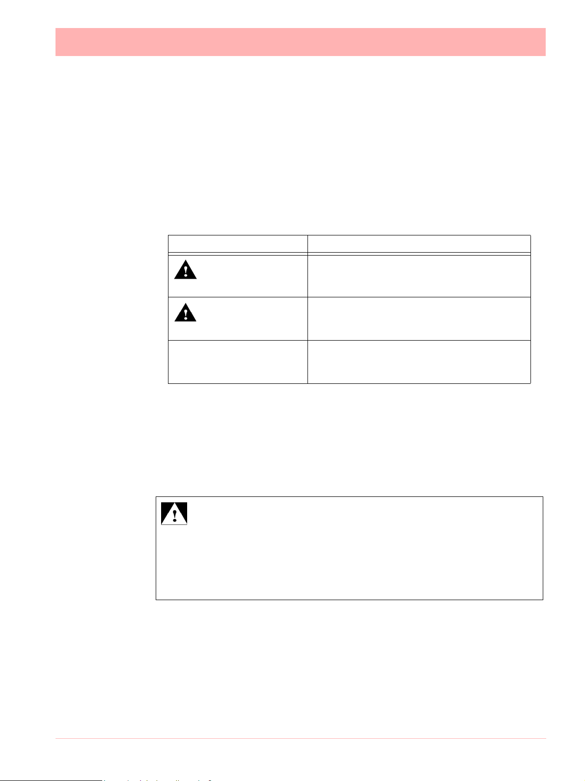
Table 1.2 : Safety Symbols
Symbol Meaning
Caution - refer to manual for
instructions
Caution - risk of electric
shock
Direct Current
Protective conductor terminal
Earth (ground) terminal
Static Electricity
Directive 2002/96/EC
WEEE: Waste Electrical and
Electronic Equipment
2 43-TV-25-30 Iss.6 GLO Aug 07 UK
Page 9
Static Electricity
All circuit boards and electronic modules associated with this recorder contain components
which are susceptible to damage caused by elec trostatic discharge. Should it be necessa ry
to handle such components, appropriate precautions in accordance with ANSI/ESD S20.20
Electrostatic Discharge Control Program Standard, should be observed.
Protocols used in this manual
Safety and Symbol Identification
Symbol Description
Table 1.3 :
WARNING
CAUTION
NOTICE
Warnings and Safety Precautions
Do’s and Don’ts
1. Before any connections are made to the recorder, ensure the protective earth terminal
is connected to a protective conductor before applying power or any other connections.
WARNING
IMPROPER INTERRUPTION OF CONNECTIONS
Any interruption of the protective conductor outside the recorder, or disconnection of
the protective earth terminal is likely to make the recorder dang erous under some fault
conditions. Intentional interruption of the protective conductor is dangerous.
Failure to comply with these instructions could result in death or serious injury.
The WARNING symbol indicates a potentially
hazardous situation, which, if not avoided, could
result in death or serious injury.
This CAUTION symbol may indicates a potentially hazardous situation, which, if not avoided, may
result in property damage.
A NOTICE symbol indicates important information that must be remembered and aids in job
performance.
In order to comply with the requirements of safety standard EN 61010-1:2001, the
recorder should have one of the following as a disconnecting device, located within
easy reach of the operator, and be clearly labelled as the disconnecting safety device:
• A switch or circuit breaker which complies with the requirements of IEC 60947-1 and
IEC 60947-3.
• A separable coupler which can be disconnected without the use of a tool.
43-TV-25-30 Iss.6 GLO Aug 07 UK 3
Page 10

• A separable plug, without a locking device, to mate with a socket outlet in
the building.
2. Whenever it is likely that protection has been impaired, the recorder should be made
inoperative and secured against operation. The manufacturer's service centre should
be contacted.
3. Repair is not to be attempted by a customer. Any adjustment or maintenance expected
of an operator as part of the normal operation of the product is referred to as Operational Maintenance. Any maintenance not expected of the operator is referred to as
Corrective Maintenance and is to be carried out only by authorized service personnel
or returned to an authorized repair centre.
4. Where conductive pollution such as condensation or conductive dust is present, adequate air conditioning, filtering and/or sealing must be installed.
5. This recorder contains one battery on the Processor board which must be treated and
disposed of with care. Batteries must not be short circuited. Batteries should be disposed of in accordance with local regulations, they must not be disposed of with normal
refuse.
Improper signal and supply wiring - WARNING
6.
WARNING
IMPROPER SIGNAL AND SUPPLY WIRING
Signal and supply wiring should be kept separate. Where this is impractical, shielded cables should
be used for the signal wiring. Where signal wiring is carrying, or could carry under fault conditions,
hazardous voltage (defined as >30 V rms and 42.4 V peak, or >60 Vd.c.), double insulation must
be used for all signal wiring.
Failure to comply with these instructions could result in deat h or serious injury.
7. If the equipment is used in a manner not specified by the manufacturer, the protection
provided by the equipment may be inadequate.
8. The protective earth terminal must remain connected (even if the recorder is isolated
from the mains supply) if any of the measuring, communications, or relay terminals are
connected to hazardous voltages.
Hazardous Voltage
Hazardous Voltages are defined by EN61010-1 as follows:
WARNING
HAZARDOUS VOLTAGE LEVELS
Voltage levels above 30V rms and 42.4V peak or 60V dc are deemed to be
"Hazardous Live". Ensure operators are not exposed to hazardous voltage levels.
Failure to comply with these instructions could result in death o r se rious injur y.
4 43-TV-25-30 Iss.6 GLO Aug 07 UK
Page 11

Section 2: Installation
Damage checks
Any damage caused to the recorder or the contents should be reported immediately to your
shipper.
Unpacking
Remove the contents, check the packaging and re move all documentation and accessories
supplied. Retain the box and any packaging for future transportation.
Contents
Check that the contents and accessories are correct against the order or Model Selection
Guide using the model number on the recorder. Contact your authorised Honeywell dis-
tributor or Honeywell immediately should there be any query.
The contents are based on Unit Model Number ordered and will vary from unit to unit. The
following list is provided as a general guide and not specific to any single unit.
• Recorder - specification as ordered (check against the Model Selection Guide)
• Mounting fixings - Mounting clamps and panel gasket
• Connector kit - mating half connectors to recorder spec. Including a CJC connector for
Thermocouple operation.
• Quick Start Guide - to get you started
• First time Password system instructions - for ESS recorders only
• CD - Viewer software + documentation
• Plastic stylus x 2 (for use with the touch screen)
• Manual (optional) - Hard copy English, French or German
• Any other items ordered as an option (Model Selection Guide)
Re-packing
NOTICE
Should the original packing be destroyed or lost, new packaging can be ordered or as a
last alternative, then ONLY pack the recorder in polystyrene granules if the recorder is
FIRST sealed in a strong plastic bag. Failure to do this will invalidate your warranty.
Environment and Location
• The recorder is designed to be mounted into a panel. See “Installation Instruc-
tions” on page 9.
• Mounting angle is unlimited. Choose a suitable location with an ideal viewing angle.
See “Mounting and Viewing Angles” on page 6.
• The location should be free from vibration.
• The environment should be of non-condensing humidity.
• The ambient temperature should be between 0C and 50C (32F to 122F).
• The relative humidity should be between 10% to 90%.
43-TV-25-30 Iss.6 GLO Aug 07 UK 5
Page 12
NOTICE
The eZtrend QXe recorder is an Emissions Class A product. In a domestic environment this product may cause radio interference in which case the user may be required
to take adequate measures.
Mechanical Installation
Mounting and Viewing Angles
Mounting - The Minitrend QX, Multitrend SX and eZtrend QXe recorders have an unlimited mounting angle.
Viewing - For the best view of the display the v
Minitrend QX 55from the left or right, 40looking down and 50 looking up at the recorder dis-
play.
Multitrend SX 70from the left or right, 45looking down and 55 looking up at the re-
corder display.
eZtrend QXe 45f rom the left or righ t, 10looking down and 30 looking up at the recorder display.
iewing angle should not exceed:
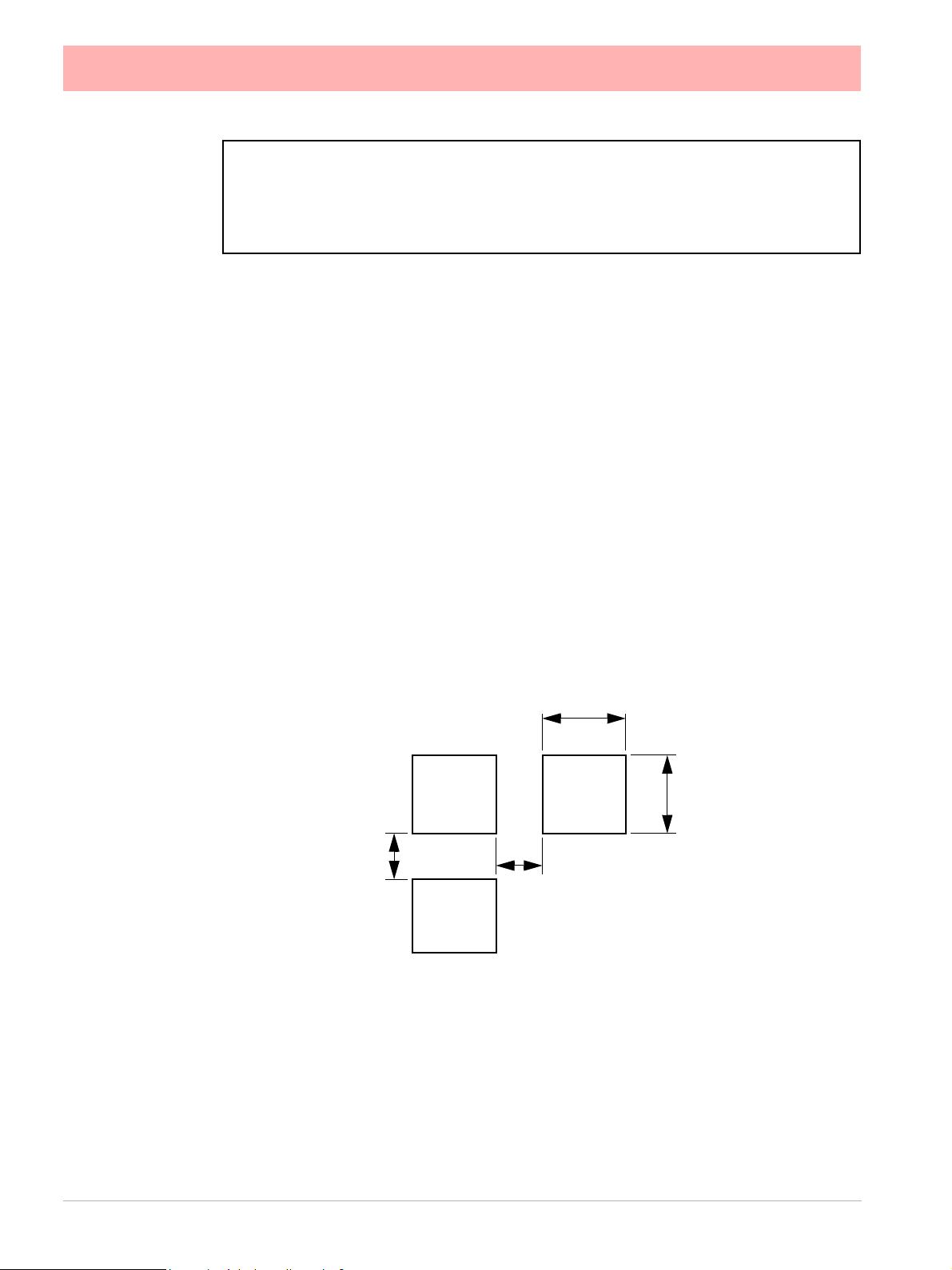
Panel cut-out size for the Minitrend QX and eZtrend QXe recorders
+1
- 0
138.00
(5.43”)
+1
- 0
>6.00
(0.237”)
Panel
Cut-out
138.00
(5.43”)
Panel
Cut-out
>7.00
(0.28”)
Panel
Cut-out
Figure 2.1 Minitrend QX and eZtrend QXe Panel cut-out
6 43-TV-25-30 Iss.6 GLO Aug 07 UK
Please note the recommended
spacing for adjacent mounting
Page 13

Panel cut-out size for the Multitrend SX recorder
281.00
(11.06”)
Panel
Cut-out
Panel
Cut-out
281.00
(11.06”)
>20.00
>20.00
(0.787”)
(0.787”)
Panel
Cut-out
Please note the recommended
spacing for adjacent mounting
Figure 2.2 Multitrend SX Panel cut-out
The Minitrend QX, Multitrend SX and eZtrend QXe recorders ar e DIN Standard sizes
and should be panel mounted.
43-TV-25-30 Iss.6 GLO Aug 07 UK 7
Page 14
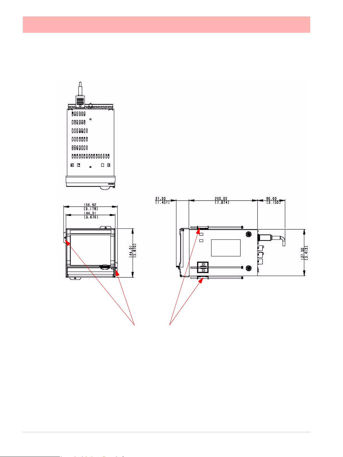
Minitrend QX Dimension details
4 Mounting clamp positions. For standard units fit only two
brackets on opposite sides of the unit, either top and bottom
or left and right slots. NEMA 4X rated recorders require all four
mounting brackets to be fitted.
Figure 2.3 Minitrend QX Recorder dimensions
8 43-TV-25-30 Iss.6 GLO Aug 07 UK
Page 15
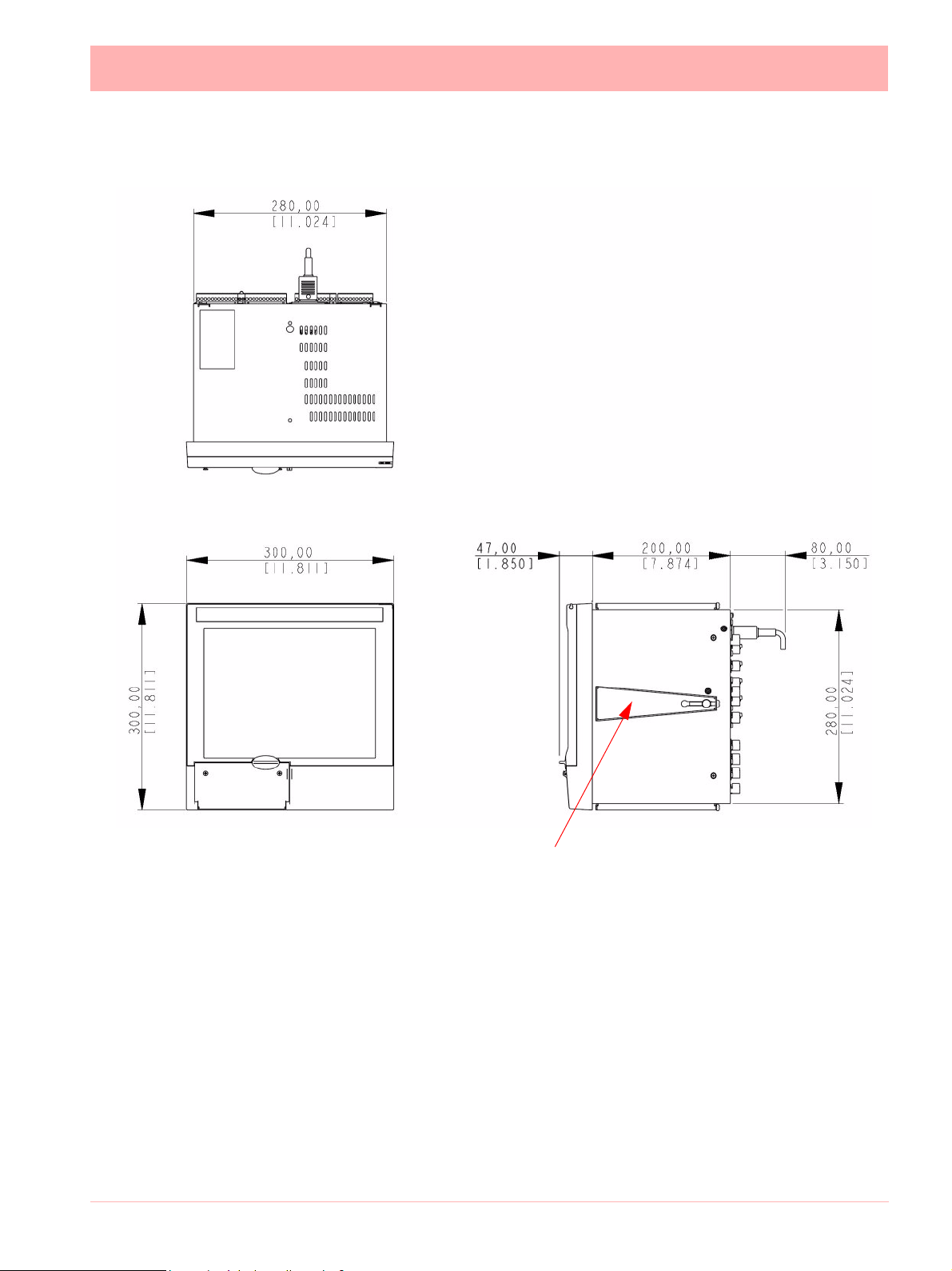
Mu l t i t r e n d S X Dimension details
4 Mounting clamp positions. For standard units fit only
two brackets on opposite sides of the unit, either top
and bottom or left and right slots. NEMA 4X rated recorders require all four mounting brackets to be fitted.
Figure 2.4 Multitrend SX recorder dimensions
Installation Instructions
• Minimum panel thickness = 2mm (0.078”), max = 20mm (0.78”)
• Both recorders must be inserted from the front of the panel,
• Two mounting clamps are supplied and can be fixed either on the top and bottom
sides or on the left and right sides of the case.
43-TV-25-30 Iss.6 GLO Aug 07 UK 9
Page 16

eZ t r e n d Q X e Dimension details
4 Mounting clamp positions. For standard units fit only two
brackets on opposite sides of the unit, either top and bottom
or left and right slots. NEMA 4X rated recorders require all four
mounting brackets to be fitted.
Figure 2.5 eZtrend QXe recorder dimensions
10 43-TV-25-30 Iss.6 GLO Aug 07 UK
Page 17

Panel Mounting Clamp Installation
The Minitrend QX, Multitrend SX and the eZtrend QXe recorders slide into the pan el
cut-out and are held in place by two (or four) pan el clamps. The panel clam ps should be fitted on diagonally opposite sides of the unit and tightened against the re ar of the panel using
two fixing screws.
The mounting clamp assembly and fitting instructions differ slightly for the two recorders.
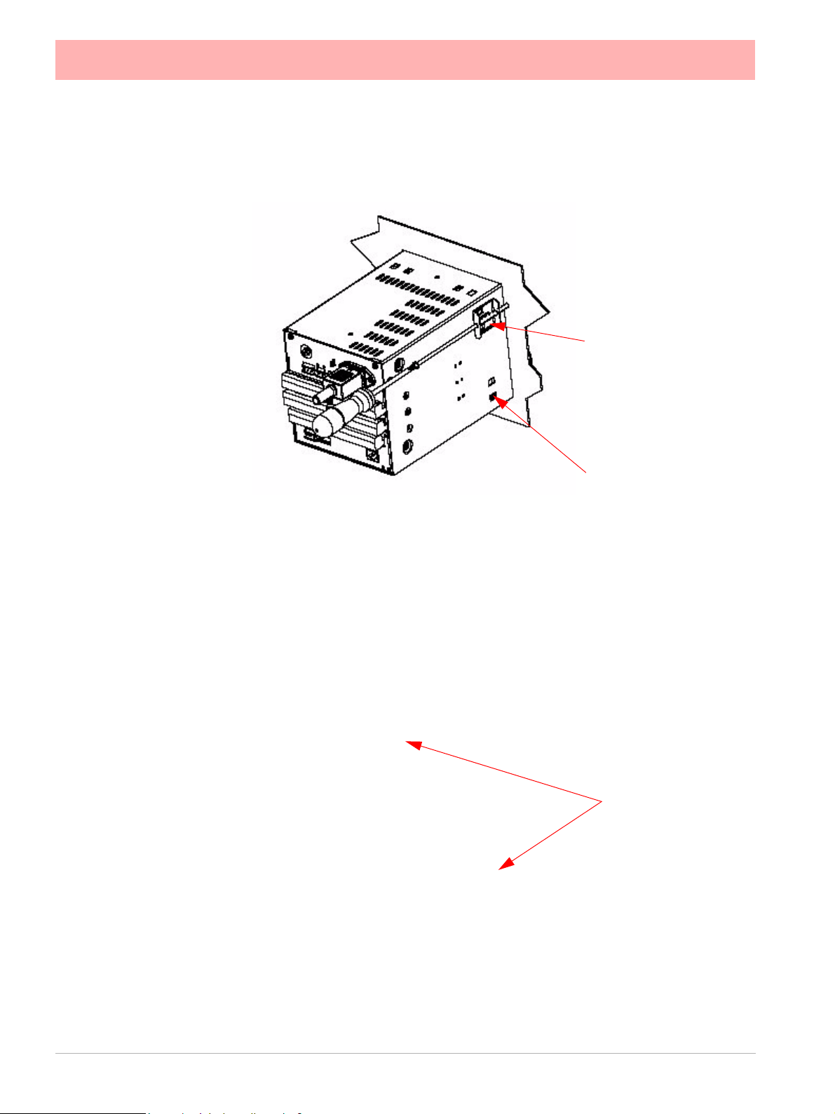
Minitrend QX and eZtrend QXe
1. Insert the panel gasket onto the recorder so it goes between the back of the
recorder bezel and the panel. From the front p anel, place u nit in the pa nel and
push through the panel.
2. To loosen each clamp, unscrew the long screw to accommodate the panel
thickness.
3. From behind the panel, the orientation of the clamp should be with the screw
head towards the rear of the unit. See .
4. Take the first clamp and locate the two lugs on the clamp into the slots on the
unit. See .
5. Take the second clamp and do the same but in the diagonal position to the
opposite side. See Figure 2.3 on page 8.
6. Tighten the screw using a flat blade screwdriver and the clamp will secure
against the panel.
CAUTION
CONTROL UNIT DAMAGE
Do not over tighten mounting clamp screws.
Minitrend QX
Multitrend SX torque setting should be 0.5 - 0.70Nm/4.4 - 6.2lbf-in
Failure to comply with these instructions may result in product damage
Multitrend SX
1. Insert the panel gasket onto the recorder so it goes between the back of the
recorder bezel and the panel. From the front p anel, place u nit in the pa nel and
push through the panel.
2. To loosen each clamp, unscrew the long screw to accommodate the panel
thickness.
3. From behind the panel, the orientation of the clamp should be with the screw
head towards the rear of the unit. See Figure 2.2 on page 7.
4. Position the circular mounting boss in the hole on on e side of the case with the
lip of the boss inside the case. Ensure the front of the clamp is up against the
panel.
5. Fix the second clamp on the opposite side of the unit. See Figure 2.4 on
page 15.
and eZtrend QXe torque setting should be 0.5 - 0.75Nm/4.4 - 6.6lbf-in
6. Tighten the screw using a flat blade screwdriver and the clamp will secure
against the panel.
43-TV-25-30 Iss.6 GLO Aug 07 UK 11
Page 18
Mounting Clamp Diagram
Figure 2.1 Minitrend QX and eZt r e n d Q X e Mounting clamp
2 mounting clamp
positions required on
two opposite sides of
the recorder. Nema 4X
requires all 4 clamps to
be fitted.
Mounting clamp slots
Figure 2.2 Multitrend SX Mounting clamp
4 mounting clamp
positions (2 shown).
2 clamps are required on opposite
sides of the recorder
12 43-TV-25-30 Iss.6 GLO Aug 07 UK
Page 19

Electrical Installation
Installation Category
• Installation category - Installation category II, Pollution degree 2
• Follow National and local electrical codes for installation in a Class 1, Div.2 area.
For voltage, frequency and power refer to the appropriate Specification sheet: See “Sec-
tion 12: Technical Data & Specifications” on page 255.
Fuses
There is a fuse situated on the DC input version power supply, type 2A time-delay, this can
be replaced by the user. Replacement of fuses should be carried out by qualified service
personnel.
If the fuse should blow again there is probably a pr oblem elsewhere within the unit and the
recorder should be returned for inspection to your authorised Honeywell distributor or
Honeywell Service department.
Cables
To fully comply with the requirements of the CE Mark, all cables connected to the rear of
the unit should use screened cable terminated at both ends. A low impedance earth cable
(<50 m) must be connected to the earthing stud on the rear of the recorde r, to ensure
that the recorder is always earthed.
Before performing any installation please read the section on “Safety” on page 2.and
“Warnings and Safety Precautions” on page 3.
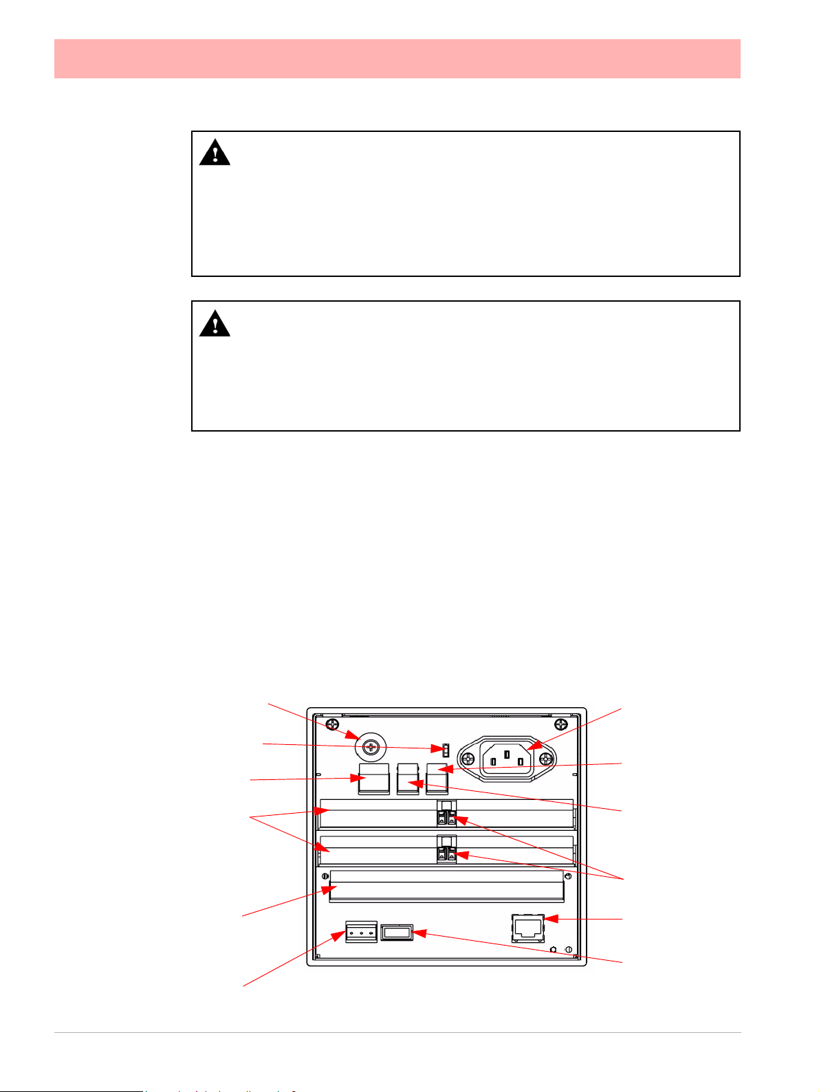
All connections to the unit are made via the rear panel, the layou t of which is sh own in Fig-
ure 2.3 on page 14
Note: The eZtrend QXe
to the recorder case using a low impedance bond. Also avoid use of a length of wire between
the cable screen and the recorder case.
Analogue Input card (Slot A). Cable screen must be well connected
Signal Wiring
WARNING
ENSURE SAFETY EARTH CONNECTION
Always ensure the unit is connected to safety earth when connecting to an AC or DC
supply.
Failure to comply with these instructions could result in death or serious injury.
Your recorder is intended for pa nel-mount u se, and only the fro nt face is intended to be
exposed to the operator. Disconnection from the supply MUST be mad e possible by
means of a switch, circuit breaker or other means of supply isolation.
The disconnection device must be included in the panel installation , clearly marke d, in
close proximity to the recorder, and within easy reach of the operator. The protective earth
terminal must remain connected (even if the recorder is isolated from the mains supply) if
any of the analogue or relay terminals are connected to hazardou s voltage.
43-TV-25-30 Iss.6 GLO Aug 07 UK 13
Page 20
CAUTION
UNIT DAMAGE CONTROL
To protect against component failures the user should fit an external fuse for the DC
input power supply. The value should be 4A, time delay, high breaking capacity, minimum 60Vdc.rated.
Failure to comply with these instructions may result in product damage
WARNING
HAZARDOUS VOLTAGES
When using the recorder as portable equipment the optional rear cover must be fitted
when hazardous voltages are connected.
Failure to comply with these instructions could result in death or serious injury.
AC Power
AC supply is connected via the standard configuration IEC chassis plug on the rear panel,
100 - 250 Vac, 50-60 Hz (40 VA Minitrend QX, eZtrend QXe and 60VA Multitrend
SX). Absolute limits 90V-132Vac (110V) and 180V-264Vac (240V)
24V AC/DC Power / 48V AC Power
For the Minitrend QX and the Multitrend SX the supply range is 24V DC +/- 10% (absolute limits are 20V to 55V DC). Also accepts 20 to 30V AC. Power to the D.C.variant is
connected via a rectangular 3-way connector as identified in Figure 2.3 on page 14 for the
Minitrend QX and Figure 2.4 on page 15 for the Multitrend SX.
The eZtrend QXethe supply range is 24V DC +/- 10% (absolute limits are 20 V to 30V DC).
Also accepts 20 to 25V AC.
Earth screw (ground)
Wire seal provision
24V DC/AC Input
Analogue Input /
Analogue Output
/ or Pulse Input
Slot A
Slot B
Alarm Relay or
Digital I/O
Slot G
RS485
AC supply
100 - 250 VAC
SPNC Relay
24V TX Power
Supply Output
CJC Sensor
Ethernet
USB Host
Figure 2.3 Minitrend QX Connector diagram
14 43-TV-25-30 Iss.6 GLO Aug 07 UK
Page 21
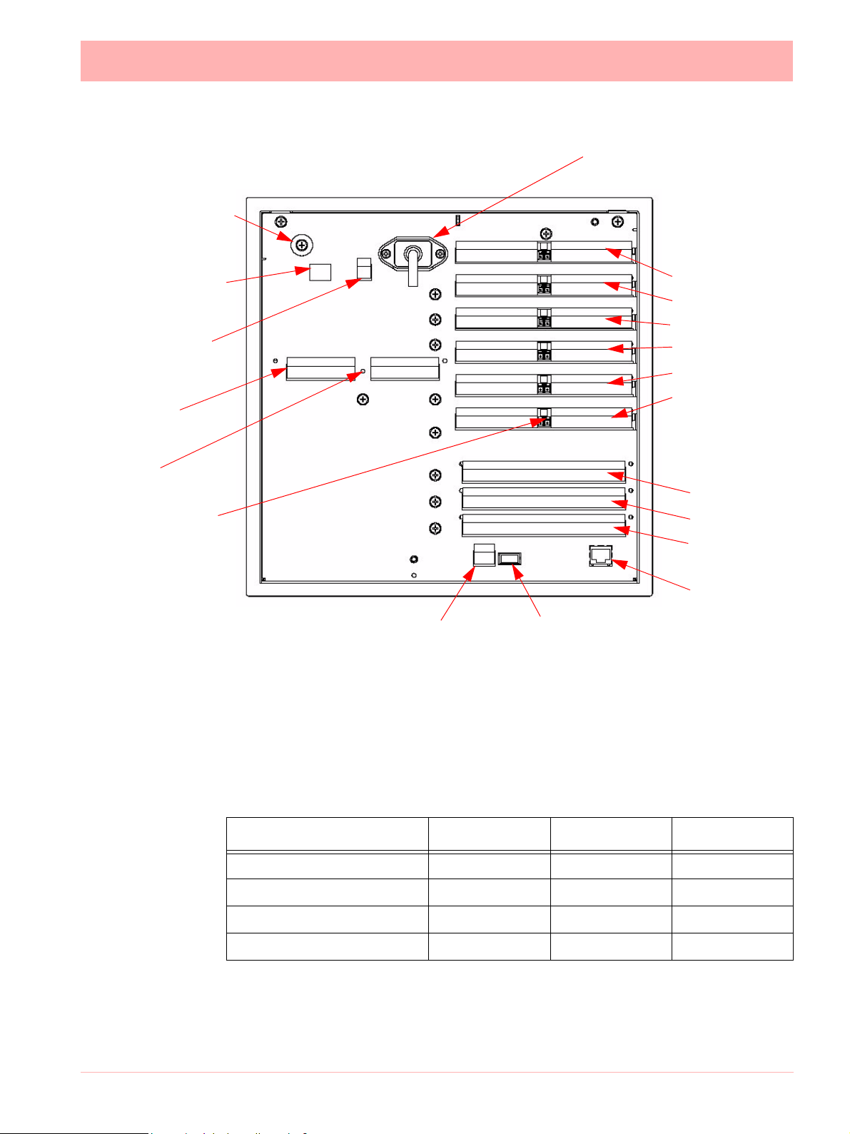
AC supply
100 - 250 VAC
Earth screw
(ground)
24V DC/AC Input
SPNC
Relay
24V TX
Power Supply
Output
LED
CJC Sensor
position in the
middle of the
Analogue Input
connector.
Slots A - F
Analogue Input/
Analogue Output/
or Pulse Input
Slot A
Slot B
Slot C
Slot D
Slot E
Slot F
Alarm Relay
or
Digital I/O
Slot G
Slot H
Slot I
Ethernet
RS485 USB Host
Figure 2.4 Multitrend SX Rear p anel
Card and Slot positions
Table 2.1 : Card priority positions
Cards
Analogue Input card A, B A, B, C, D, E, F A*, B (option)
Analogue Output card B E, F Pulse Input card A, B A, B, C, D, E, F Alarm Relay or Digital I/O card G G, H, I G
“QXe Analogue Input (Standard) card” on page 19
43-TV-25-30 Iss.6 GLO Aug 07 UK 15
Minitrend QX Multitrend SX eZtrend QXe
Page 22

Earth screw
(ground)
Analogue Input
card (option)
Slot B
CJC Sensor
24V TX Power
Supply Output /
RS485 port /
USB Host card
(option)
Wire seal provision
24Vdc TX
RS485
20 to 30VDC / 20 to 25VAC Input
Instrument power (option)
AC supply
100 - 250 VAC
Alarm Relay or
Digital I/O
Slot G (option)
USB
ETHERNET
Analogue Input /
Ethernet connection
card (std) - Slot A
Figure 2.5 eZtrend QXe Rear panel
Analogue Input Card
Each Analogue Input card has up to 8 input channels for th e Minitrend QX and the Multitrend SX and up to 6 channels for the eZtrend
way screw terminal plugs that fit into a PCB header on the rear of the unit. The 2- way CJC
sensor should remain fitted in the central 2-way header.
The Minitrend QX
can have two analogue input cards fitted giving up to 16 input channels
(2 x 8 channel cards). The slot positions are A & B, these are identified on the rear p anel on
the back of the unit. Either slot can be used, it is recommended that slot A is used if only one
card is fitted.
The Multitrend SX can have up to 6 analogue input cards fitted, up to 48 inpu t channels.
The slot positions A, B, C, D, E or F; these are identified on the rear panel. PC boards are
fitted in order, slot ”A” starts from the top.
The eZtrend
QXe can use this card as an additional Analogue Input card fitted in Slot B,
providing up to 6 more channels. This card would be used after using the 3 or 6 channel
standard eZtrend
QXe Analogue Input card which is fitted in Slot A, see “QXe Analogue
Input (Standard) card” on page 19.
QXe. Connections are made via 2 x 12-
To fit this option card into the eZtrend QXe recorder you will require an expansion card to
interface to the recorder. See “QXe Analogue Input (Standard) card” on page 19.
16 43-TV-25-30 Iss.6 GLO Aug 07 UK
Page 23

WARNING
HAZARDOUS VOLTAGES
Insulation from channel to channel: Normally a channe l can be sa fely conn ected to a
hazardous voltage up to 300V AC common mode* with respect to earth. However,
where a channel is connected to a safety low voltage circuit, an immediately adjacent
channel must be adequately insulated from hazardous voltages between 150V AC
and 300V AC max. This insulation should comprise of at least 1.5mm air gap, or a barrier rated greater than 1400V AC. This is to ensure that protection of the safety low
voltage circuit is fully maintained.
*Common Mode voltage is a voltage applied between the whole channel and earth,
not between pins on a channel. 300V AC is permitted at M easurement Category CAT
ll (Overvoltage Category ll)
Failure to comply with these instructions could result in death or serious injury.
NOTICE
For 12 and 24-way connectors; torque setting 0.4 Nm/3.5lbf-in. Do not over tighten.
Recommended wire size for termination connector is 22-12 AWG (American Wire
gauge) equivalent to 22-14 SWG (Standard Wire Gauge). AWG metric 0.6426-
2.052mm in diameter or SWG metric 0.71 - 2.03mm in diameter.
Analogue Input Channel Numbers
Analogue Input cards are either 4, 6 or 8 channels with a full length connector taking up 8
channels even if only 4 or 6 are operational.
Table 2.2 :
Minitrend QX and Multitrend SX Analogue Input card
Card Position
Channel number 1 to 8 9 to 16 17 to 24 25 to 32 33 to 40 41 to 48
Slot A Slot B Slot C Slot D Slot E Slot F
Table 2.3 :
Card 3 CH. 6 CH. 9 CH. 12 CH.
A 1-3 1-6 1-3 1-6
B 9-14 9-14
eZtrend QXe Analogue Input cards
Analogue Input Connection Details
Current Input
For Current (mA) Input fit a 10
analogue connector. Figure 2.7 on page 19 shows a 10
nel 5 for a current (mA) input.
resistor across the + and - pins of the 12-way mating half
(±0.1%) resistor fitted to chan-
43-TV-25-30 Iss.6 GLO Aug 07 UK 17
Page 24
Thermocouples
Ensure polarity of thermocouple is correct.
Resistance Thermometers
If using 2 wire R/T the + and - terminals must be linked together. See Figure 2.7 on
page 19.
Analogue Input Signal Wiring
CAUTION
CONTROL UNIT DAMAGE
Do not apply a hazardous live voltage between + and - pins within a channel. ( eg. 60V
maximum on voltage ranges, 5V maximum on millivolts ranges). Do not apply a voltage
above 1.2V to the * pin.
Failure to comply with these instructions may result in product damage
Figure 2.6 Analogue Input connector
CJC
CH1 CH2 CH3 CH4 CH5 CH6 CH7 CH8
This Analogue Input card can be used as an option to add up to 6 more Analogue Input
channels for the eZtrend QXe
numbers 9 to 14. The standard fit Analogue Input card is fitted in slot A with up to 6 channels
(channels numbers 1 to 6).
To fit this option card into the eZtrend QXe recorder you will require an expansion card to
interface to the recorder. See “QXe Analogue Input (Standard) card” on page 19.
recorder. This will fit into Slot B and will display as channel
18 43-TV-25-30 Iss.6 GLO Aug 07 UK
Page 25
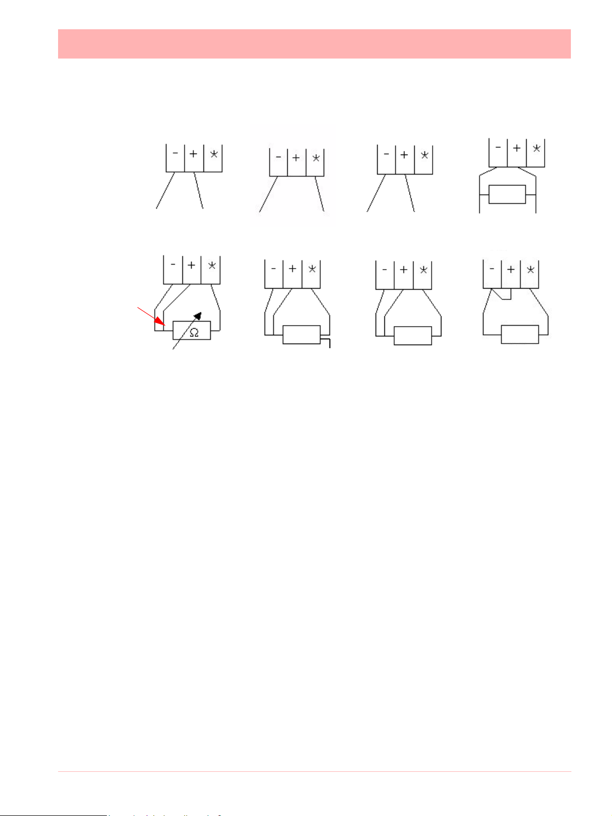
Figure 2.7 Input signal wiring
+ve optional
connection
Active Burnout
Volts/mV
-ve +ve
Ohms
Recorder setup will be required if wiring changes are made for Active Burnout Thermocouples. See “*Thermocouple Wiring Changes.” on page 57.
Thermocouple Active Burnout status can be viewed in the Main Menu > Status >Diagnostics
> Analogue Input screen, Input column. The Health Watch/Maintenance firmware option
must be active to access the Maintenance and Diagnostic buttons. See “Diagnostics” on
page 161.
Thermocouples
-ve
4-wire R/T
+ve
R/T
Passive Burnout
Thermocouples
-ve
3-wire R/T
+ve
R/T
Current
10R
-ve +ve
2-wire R/T
R/T
For the eZtrend QXe
the link between positive (+) and negative (-).
recorder Active Burnout is not available. Ohms measurements must have
CJC Connectors
The CJC connector resides between channel 4 and channel 5 on the Analogue Input card.
For information on connecting the CJC sensor, see Figure 2.6 on page 18.
For the eZtrend QXe
recorder this is available on the Analogue Input card (option).
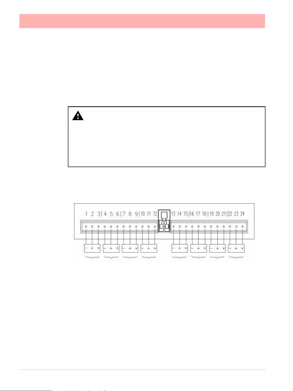
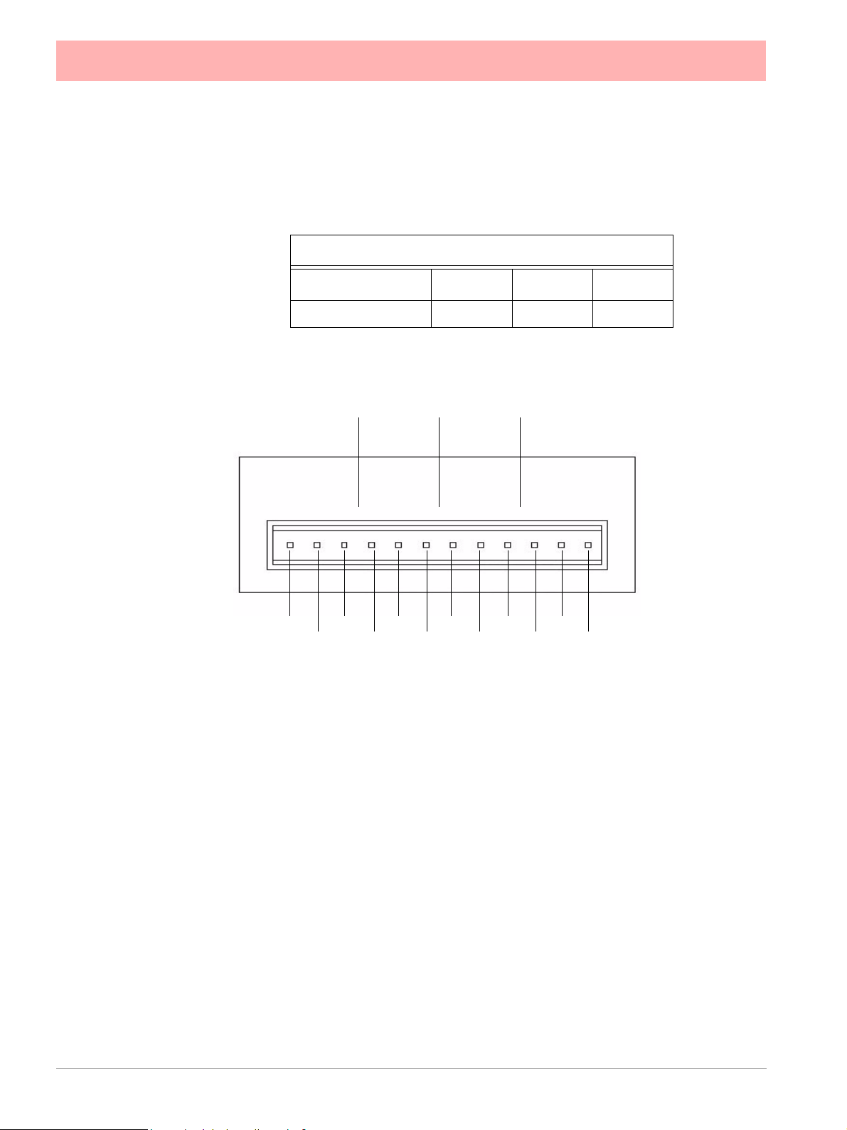
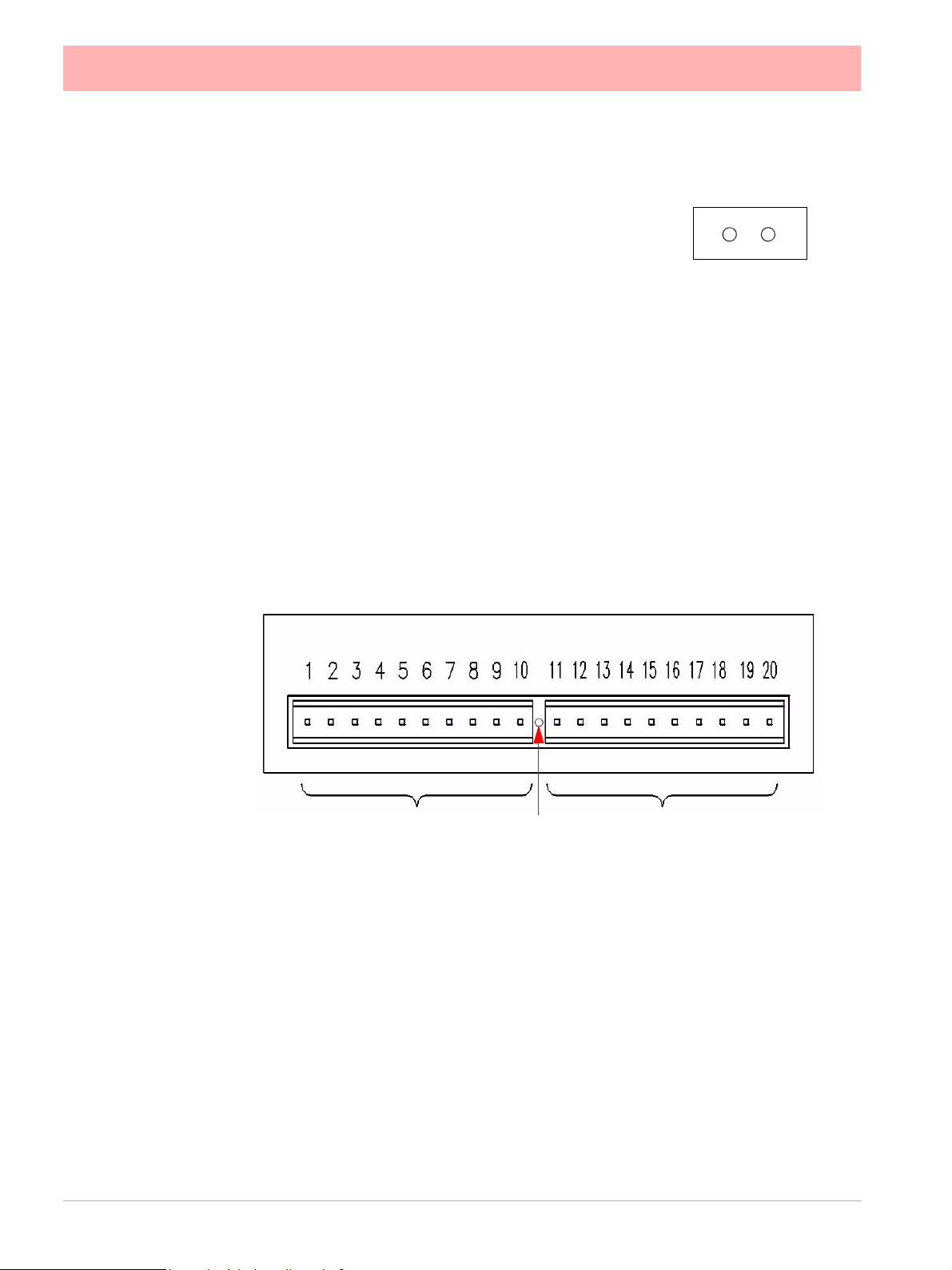
QXe Analogue Input (Standard) card
The eZtrend QXe is fitted with a standar d Analogue Input card in Slot A, with up to 6 chan-
nels. The card is also fitted with an Ethernet port as standard. Connection is made via 1 x
18-way screw terminal plugs that fit into a PCB header on the rear of the unit. To fit up to a
further 6 analogue input channels, see “Analogue Input Card” on page 16
43-TV-25-30 Iss.6 GLO Aug 07 UK 19
Page 26
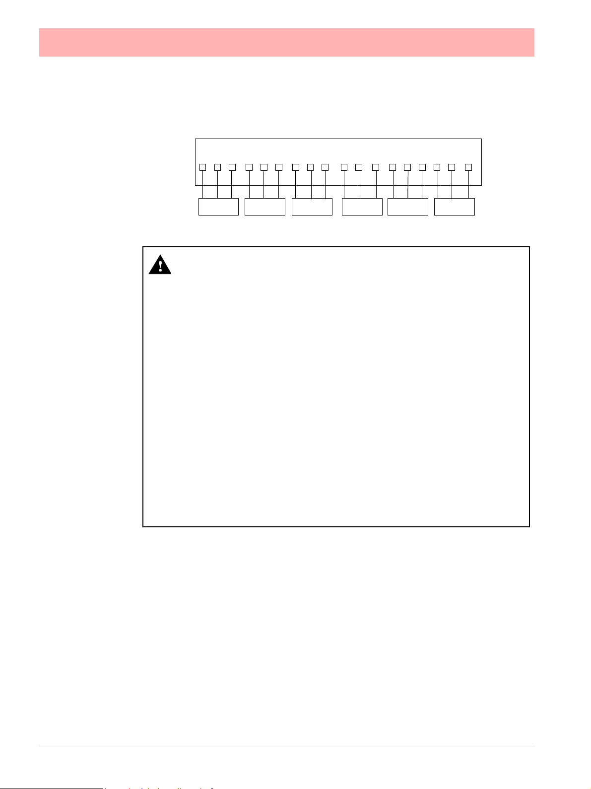
Figure 2.8 eZtrend QXe Analogue Input card (std) - Slot A
1 2 3 4 5 6 7 8 9 10 11 12
- +
CH.1 CH.2 CH.3 CH.4 CH.5 CH.6
- +
*
- +
*
- +
*
13 14 15 16 17 18
- +
*
*
- +
*
WARNING
HAZARDOUS VOLTAGES
Insulation from channel to channel: Normally a channel can be safely connected to a
hazardous voltage up to 150V AC common mode* with respect to earth. However,
where a channel is connected to a safety low voltage circuit (i.e. is accessible for operators to touch), any channel within the same 'input bank' must be limited at all time s
to a maximum of 55Vac or 140Vdc**. This is to ensure that protection of the safety low
voltage circuit is fully maintained.
The inputs are divided into two banks: inputs 1 to 3 are one bank, and inputs 4 to 6 (if
fitted) are another bank. A voltage of up to 150V AC common mod e can be applied on
one bank as long as any safety low voltage circuits are on the other bank. The recorder
is protected against accidental connection of a voltage up to 240V AC common mo de
which might occur as a temporary fault condition, provided there are no safety low voltage circuits connected to the same input bank as the channel with the fault.
*Common Mode voltage is a voltage applied between the whole channel and earth,
not between pins on a channel.
** this reduces to 33Vrms or 70Vdc if any channel within the input bank is configured
as an ohms or R/T measurement.
Failure to comply with these instructions could result in death or serious injury.
20 43-TV-25-30 Iss.6 GLO Aug 07 UK
Page 27

CAUTION
CONTROL UNIT DAMAGE
Do not apply a hazardous live voltage between + and - pins within a channel (e.g . 60V
maximum on voltage ranges, 5V maximum on millivolts ranges).
The * pin should be connected only as part of ohms or R/T me asurements. Ohm s and
R/T measurements share a common connection (* pin) with all channels in the same
bank (the inputs are divided into two banks: inputs 1 to 3 are one bank, and inputs 4 to
6, if fitted, are another bank). To avoid damage, ensure t hat a channel selected as ohms
or R/T remains floating, i.e. the sensor is not connected to any external voltage.
Alternatively, if an ohms or R/T sensor must be biased to an external voltage, ensure
that the other two channels within the same input bank a re floating or are biased to the
same voltage (i.e. - inputs of all three channels connected to the same voltage).
Failure to comply with these instructions may result in product damage
Analogue Output Card
Not available on the eZtrend QXe recorder.
The Analogue Output card connections are made via 1 x 12- way screw te rminal plug that
fits into a PCB header on the rear of the unit.
The Analogue Output card position for the Minitrend QX
page 14, and Figure 2.4 on page 15 for the Multitrend SX.
is shown in Figure 2.3 on
WARNING
HAZARDOUS VOLTAGES
Insulation from channel to channel: Normally a channel can be safely connected to a
hazardous voltage up to 300V AC common mode* with respect to earth. However,
where a channel is connected to a safety low voltage circuit, an i mmedi ately adjace nt
channel must be adequately insulated from hazardous voltages betwe en 150V AC and
300V AC max. This insulation should comprise of at least 1.5mm air gap, or a barrier
rated greater than 1400V AC. This is to ensure that protection of the safety low voltag e
circuit is fully maintained.
*Common Mode voltage is a voltage applied between the whole channel and earth, not
between pins on a channel. 300V AC is permitted at Measurement Category CAT ll
(Overvoltage Category ll)
Failure to comply with these instructions could result in death or serious injury.
43-TV-25-30 Iss.6 GLO Aug 07 UK 21
Page 28
Analogue Output Channel Numbers
The Analogue Output cards are eith er 2 or 4 ch annels using a connector that on ly takes up
half the length of the connector slot. Looking from the rear of the unit the Analogue Out connector is on the left of the Analogue slot with a blanking plate on the right.
Table 2.4 :
Analogue Output card
Card Position
Channel number 9 to 12 33 to 36 41 to 44
Slot B Slot E Slot F
Analogue Output Connection Details
Output 1 Output 2 Output 3
1 2 3 4 5 6 7 8 9 10 11 12
Loop -
Loop +NCLoop -
Loop +
Loop -
NC
Loop +NCLoop -
Output 4
Loop +
NC
NC = Not
connected
Pulse Input Card
The Pulse Input card connections are made via 1 x 12-way screw terminal plugs that fits
into a PCB header on the rear of the unit.
The Pulse Input card position for the Minitrend QX
and Figure 2.4 on page 15 for the Multitrend SX.
The Pulse Input card is not available on the eZtrend QXe
O option card has 4 channels that can be set as pulse inputs (channels 1 to 4). Th e operating frequency for pulse inputs on the Digital I/O card is 1kHz max.
Input: Low < 1V, High >4V to <50V DC (8V to 50V p-p AC) or Volt free input: Low = short
circuit, High = open circuit.
22 43-TV-25-30 Iss.6 GLO Aug 07 UK
is shown in Figure 2.3 on page 14,
recorder, however, the 8 Digital I/
Page 29
WARNING
HAZARDOUS VOLTAGES
Insulation from channel to channel: Normally a channel can be safely connecte d to a
hazardous voltage up to 300V AC common mode* with respect to earth. However,
where a channel is connected to a safety low voltage circuit, an immediately adjacent
channel must be adequately insulated from hazardous voltages between 150V AC
and 300V AC max. This insulation should comprise of at least 1.5mm air gap, or a barrier rated greater than 1400V AC. This is to ensure that protection of the safety low
voltage circuit is fully maintained.
*Common Mode” voltage is a voltage applied between the whole channel and earth,
not between pins on a channel. 300V AC is permitted at Measurement Category CAT
ll (Overvoltage Category ll)
Failure to comply with these instructions could result in death or serious injury.
Pulse Input Channel Numbers
The Pulse Input card has channels using a connector that only takes up half the length of
the connector slot. Looking from the rear of the unit th e Pulse Input connector is o n the right
of the slot with a blanking plate on the left.
Table 2.5 :
Pulse Input card
Card Position
Channel number 1 to 4 9 to 12 17 to 20 25 to 28 33 to 36 41 to 44
Slot A Slot B Slot C Slot D Slot E Slot F
Pulse Input Connection Details
Do not connect anything to terminals marked NC (Not Connected). For F requency and Voltage levels see “Specification Tables” on page 259.
Channel 1 Channel 2 Channel 3 Channel 4
- + NC - + NC - + NC - + NC
43-TV-25-30 Iss.6 GLO Aug 07 UK 23
Page 30
Transmitter Power Supply Card
The Minitrend QX Transmitter power supply option is
24V DC 200 mA and is fitted to the power supply card
within the unit. Connection is made via a 2-way connector
at the rear of the unit, the mating half is supplied with this
option. For connector position see Figure 2.3 on
page 14. The 24V transmitter power supply is not isolat-
ed from the recorder, and is not referenced to ground.
The Multitrend SX
the power supply card within the unit. Connectio n is made via two 10-way connectors, see
Figure 2.4 on page 15, mating halves su pplied with this option. The Multitrend SX trans-
mitter power supply is isolated from the recorder.
A red LED light will illuminate when there is voltage on the connectors. The LED is situated
between the two connectors at the back of the unit. Figure 2.4 on page 15.
The eZtrend QXe has a 24V DC 130mA Transmitter Power Supply card that can be fitted
as an option. Connection is made via a 2-way connector at the rear of the unit, the mating
half is supplied with this option. For connector position see Figure 2.3 on page 14. The
24V transmitter power supply is not isolated from the recorder, and is not referenced to
ground. The option card also has an RS485 Modbus port and a USB port.
Recommended wire size for termination connector 22-12 AWG (22-14 SWG).
Transmitter power supply option is 24V DC 1 A and is fitted below
24V 0V
Minitrend 24V DC TXP
24V
Figure 2.9 Transmitter Power Supply card for the Multitrend SX recorder
LED
0V
Alarm Relay Cards & Digital Input/Output Cards
The Alarm Relay Cards and the Digital Input/Output Cards are both option s available for
the Minitrend QX, Multitrend SX and the eZtrend QXe recorders.
To fit these option cards into the eZtrend QXe recorder it requires an expansion card to
interface to the recorder. See “QXe Analogue Input (Standard) card” on page 19.
All Alarm Relay card outputs provide 240V AC isolation channel to chann el and channe l to
recorder. Digital Input/Outputs will provide isolation to 100V AC test voltage (not for mains
connection).
All digital inputs have volt free contacts, and are sampled at 10Hz max.
24 43-TV-25-30 Iss.6 GLO Aug 07 UK
Page 31

The Minitrend QX and the eZtrend QXe reco rders have only one slot available for digital
inputs and relay outputs for either a 4 or 8 channel Alarm Relay card or an 8 or 16 chann el
Digital I/O card fitted in slot G, the position is identified on the rear panel. The 16 channel
Digital I/O card is not available on the eZtrend QXe recorders.
The Multitrend SX can have up to three Alarm Relay cards fitted in any combination of
Alarm Relay card or Digital I/O cards. The fir st Alarm Relay card or Digital I/O card is fitted
in slot G, any additional cards will locate in positions H and I.
WARNING
HAZARDOUS VOLTAGES
Digital Input/Output card channels must not be connected to any hazardous live voltages (no higher than 30V AC rms or 60V DC).
Alarm Relay Card channels
Alarm Relay Card channels can be connected to hazardous voltages up to 300V AC,
at Measurement Category CAT II (Overvoltage Category II)
Failure to comply with these instructions could result in death or serious injury.
NOTICE
For 12 and 16-way connectors; torque settin g 0. 4 Nm/3.5lb-in. Do not over tighten.
Recommended wire size for termination connector is 22-12 AWG (22-14 SWG)
4 and 8 Alarm Relay Cards
The 24-way connector for the Alarm Relay Card, connects to 3 A, 240 VAC SPCO relays.
The pin-outs for 4 and 8 relay Alarm Relay cards are numbered from left to right and they
read as follows for each channel; NC (normally closed), C (common), NO (norm ally open ).
Devices driven by the relays are connected via two 12-way screw terminal plugs.
The last two channels, 7&8, 23&24 or 39&40, can be used as digital inputs, connect across
Common (C) and Normally Open (NO).
CAUTION
IMPROPER MAINS SWITCHING
For 8 channel Alarm Relay cards.
Switching mains on the normally-open contact on cha nnels 7 and 8 is not recommended,
as surges and spikes on the mains supply could cause damage to the input circuitry.
The normally-closed contact is unaffected, and can be used like all the other channels.
A Form C dry contact relay is used for this type of card. The inputs are designed to accept
“Dry contact, no volt inputs”. The relays should be used for non-inductive loads only where
a device requires a voltage to operate it, such as a 12 Volt buzzer, connect it to the normally
open (NO) contacts (unless the fail-safe setting is activated).
The maximum voltage which may be used with the alarm relays is 240V
43-TV-25-30 Iss.6 GLO Aug 07 UK 25
Page 32

Alarm Relay Channel Numbers
The Alarm Relay cards are either 4 or 8 channels with a full length connector taking up 8
channels even though the cards only operate on 4 channels or 8 ch annels. The 8 channels
Alarm Relay card has 2 digital inputs available on the last 2 channels. There are no Digital
Inputs available on the 4 channels Alarm Relay card.
Table 2.6 :
Alarm Relay card 4 channel Alarm Relay card 8 channel
Card
position
Slot G 1 to 4 N/A Slot G 1 to 8 7 & 8
Slot H 17 to 20 N/A Slot H 17 to 24 23 & 24
Slot I 33 to 36 N/A Slot I 33 to 40 39 & 40
Channel
number
Figure 2.10 Alarm Relay Card connector details
Digital
Inputs
Card
position
Channel
number
Digital
Inputs
CH 1 CH 2 CH 3 CH 4 CH 5 CH 6 CH 7 CH 8
NC C NO NC C NO NC C NO NC C NO NC C NO NC C NO NC C NO NC C NO
Relay contacts position
NC = Normally Closed
C = Common
NO = Normally Open
Channels 7 and 8 can
be set as Digital Inputs.
(Use C and NO)
8 and 16 Digital Input/Output Card
The 16 channel Digital I/O card is not available on the eZtrend QXe recorders.
The
Digital Input/Output Card has 1A 24V DC rated relays th at are con nected via two 16-
way connectors, the left connector for the first 8 channels and right connector for the second
8 channels. The pin-outs for 8 and 16 I/O cards are labelled from left to right, 1 to 16 on the
left side and 17 to 32 on the right. Each channel can be se t up as an input o r an output. For
output the relay is normally open type.
A Form A dry contacts relay is used for this type of card. The inputs are designed to accept
“Dry contact, no volt inputs”.
26 43-TV-25-30 Iss.6 GLO Aug 07 UK
Page 33

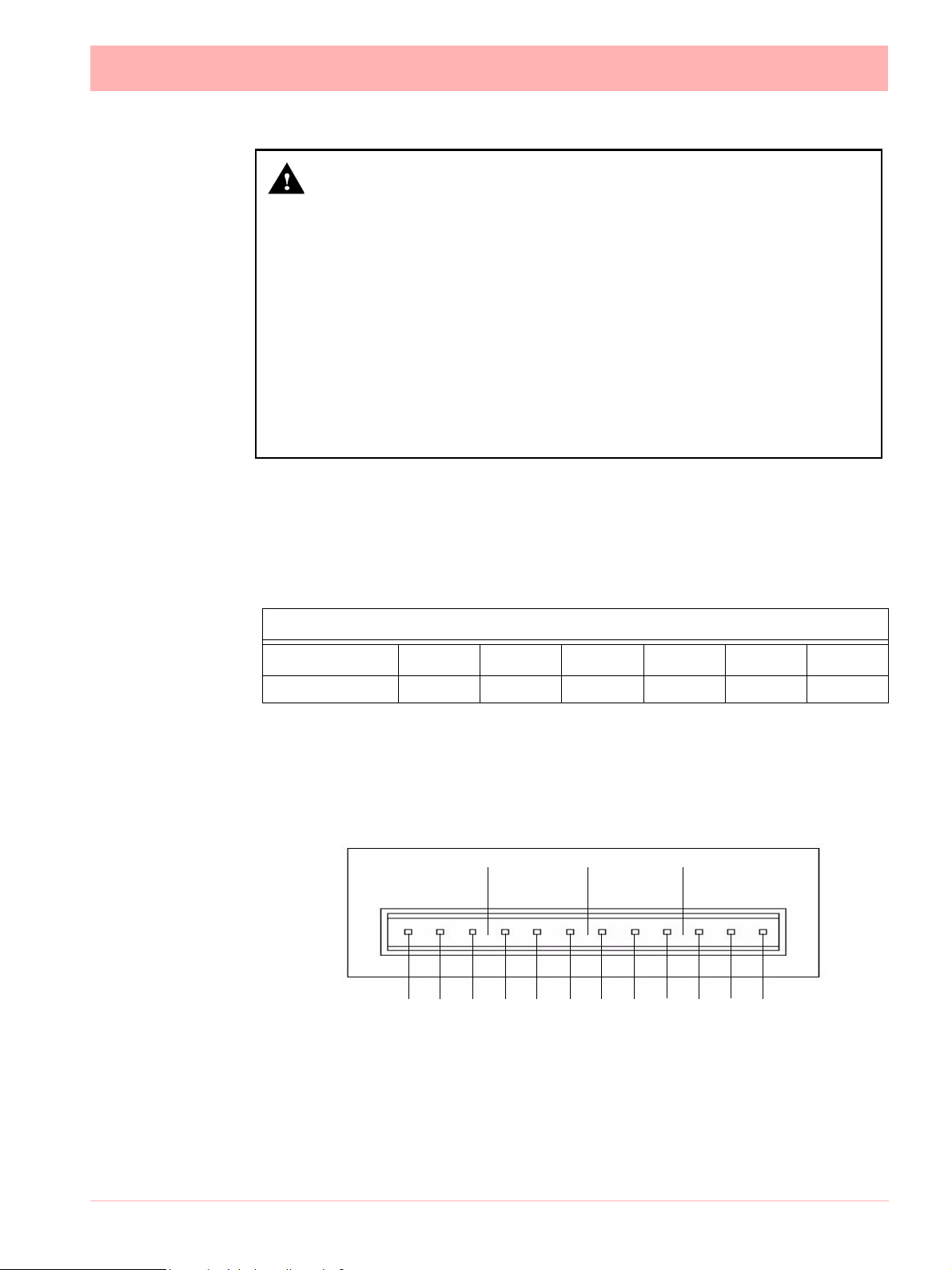
NOTICE
For Digital Inputs, short together the 2 pins of the channels with a switch or a relay.
Pulse Inputs
The 8 and 16 Digital I/O option card has 4 channels that can be set as pulse inputs (first 4
channels). The operating frequency for pulse inputs on the Digital I/O card is 1kHz max.
Input: Low < 1V, High >4.5V to <10V DC (9V to 20V p-p AC) or Volt free input: Low = short
circuit, High = open circuit.
.
Figure 2.11 Digital Input/Output card connector details
CH1 CH2 CH3 CH4 CH5 CH6 CH7 CH8
1 2 3 4 5 6 7 8 9 10 11 12 13 14 15 16 17 18 19 20 21 22 23 24 25 26 27 28 29 30 31 32
NO C NO C NO C NO C NO C NO C NO C NO C NO C NO C NO C NO C NO C NO C NO C NO C
CH9 CH10 CH11 CH12 CH13 CH14 CH15 CH16
NO = Normally Open
C = Common
Digital Input Card Channel Numbers
The Digital input cards are either 8 or 16 channels with a full length connector taking up 16
channels even if only 8 channels are in operation. Both the digital input cards can be used
as a relay card if required.
Table 2.7 :
Digital Input card 8 channel
Card
position
Channel
number
Digital Input card 16
channel
Card
position
Channel
number
Slot G 1 to 8 Slot G 1 to 16
Slot H 17 to 24 Slot H 17 to 32
Slot I 33 to 40 Slot I 33 to 48
The 16 channel Digital I/O card is not available on the eZtrend QXe.
43-TV-25-30 Iss.6 GLO Aug 07 UK 27
Page 34

Communications Connections
Ethernet
The Ethernet port is fitted to all X Series recorders as standard and uses a standard RJ45
Ethernet connection. After connect ion , se lec t th e Eth er n et p or t fr om th e Com ms menu and
select the required protocol from the Protocol menu eg.Modbus.
2468
8 7 6 5 4 3 2 1
RD-
RD+
TD-
TD+
1735
A
B
RJ45 Pin 1 is to the right
from the rear of the unit
24V DC Instrument Power Input
1 2 3
24V DC instrument power is available on all X Series recorders as an option. It is connected using 3- way connector , mating half is supplied. Diagram shows a view looking from the
+ - GND
rear of the unit.
eZtrend QXe Comms card
An option card is available with RS485 Modbus port and USB device connections. The card
can be purchased and fitted at any time. The RS485 connection uses a 3-way connector.
The card also has connection for 24V DC Transmitter Power Supply, see “Transmitter
Power Supply Card” on page 24.
To fit this option card into the eZtrend QXe recorder you will require an expansion card to
interface to the recorder. See “QXe Analogue Input (Standard) card” on page 19.
Figure 2.12 eZtrend QXe Comms card
24V DC TX
Power Supply
28 43-TV-25-30 Iss.6 GLO Aug 07 UK
RS485
Modbus port
USB Host
Page 35

RS485 Minitrend QX and Multitrend SX recorders.
The RS485 port is fitted as standard as a part of the processor
card and uses a 3-way connection.
After connection, select the RS485 port from the Comms
menu and select the required protocol from the Protocol menu
eg. Modbus. Diagram shows a view looking from the rear of
the unit. See “Comms Services Menu” on page 75.
1 2 3
+A -B GND
SPNC Relay Minitrend QX and Multitrend SX recorders.
(Single Pole Normally Closed). 2-way connector. This is a fail safe
relay which means if the power goes off the relay closes and can be
set to trigger an alarm. So should the power fail the relay is in a “fail
safe” condition. Diagram shows a view looking from the rear of the
unit. Either pins can be Common or Normally closed.
NOTE: Once the recorder is powered up, if there are no active alarms associated with the
“Fixed Relay”, the contacts will open. When the alarm is on they will close.
1 2
eZtrend QXe Expansion Card
This is an interface card that is required when fitting the following option cards:
• Analogue Input card in Slot B (up to 6 channels)
• Four Relay output card
• 8 Relay/2 Digital Inputs card (6 fixed Outputs/2 Configurable DI/DO)
• 8 Configurable Digital Inputs/Discrete 24V Output card
• Comms card (24Vdc Transmitter Power Supply, Rear USB Port, RS485 Comms Port)
USB Devices
Print Support
Print Support is a firmware option that can be activated using the credit system, refer to the
Options item in “Credits” on page 102.
Not all printers will be compatible with the print support feature on the recorder. The guidelines are they must be a USB printer that shows as a standard PCL (Printer Command Language). The system will not support multi function devices or printers that require specific
drivers. Avoid photo printers and printers that allow stand alone operation with cameras or
media specific printers such as pictbridge.
There isn’t a constant factor to which printers work and tho se that wont. We recommend that
you follow the guidelines outlined here and plug it in and see.
Examples of printers that are compatible with the system are:
• HP Deskjet 995C • HP Photosmart 7760 • HP DeskJet 895Cxi
• HP Laserjet 1022n • HP Laserjet 1300 • HP Deskjet 970Cxi
• HP Deskjet 450cbi • HP Laserjet 1160 • HP Deskjet 6980
• HP Deskjet 6940 • Xerox 6120N Phaser • HP Inkjet 1000
• HP Business jet 1200d • HP Business Inkjet 1000d • HP Officejet Pro K5400
To set up your printer configuration go to “Printer Menu” on page 111.
43-TV-25-30 Iss.6 GLO Aug 07 UK 29
Page 36

Keyboards
All keyboards are native USB keyboards. Local keyboard layouts are not supported; all keyboards are recognised as US layout (QWERTY).
Cordless keyboards and mice are not supported:
• Dell Model # SK-8115 Keyboard • IBM ACC42 with USB hubs
• Dell Model # C-BG17-Dual Cordless
Keyboard and Mouse Combination
• Logitech Model # LX300 Cordless
Keyboard and Mouse Combination
• IBM SK-8815 with USB hubs
• IBM SK-8806 with USB hubs
Barcode Reader
Most USB barcode readers emulate keyboards and cause no recognition prob lems. Exa mples of tested barcode readers are:
• Peninsula Phoenix 2 • Wasp - WWR 2905 Pen Scanner
• Quick Scan QS2500
• Barcode Traders LC4400 Series
USB Keys
Below are a list of USB keys known to save and load data to and from the recorders. There
will be many others that will function correctly so please test your USB key before us ing it
for recording and transferring data.
Table 2.8 :
Audio Partnership MP3 256 Corsair Flash Voyager
126MB
Intelligent Stick 128MB Kingston Data Traveller
128Mb
Lexar 128mb Jump Drive Lexar Jump Drive 64MB Lexar Jump Drive Trio SD
Memorex Travel Drive
256MB and 512MB
Netac 16MB NewLink 64MB PNY 512MB
PQI Cooldisk 128MB SanDisk Micro Cruzer 1GB SanDisk Mini Cruzer 128MB
SanDisk Titanium 512MB SanDisk Ultra II Plus 1GB Simpletech 128MB and
SumVision 64MB Super Flash drive 256MB Varta 128MB
MFlash 128MB Mobile Disk 128MB
Flash Drive 512MB
Leadtek USB2.0 128MB
Reader (Grey with 1GB SD)
and 1GB
Newlink 128, 512 and 1GB
30 43-TV-25-30 Iss.6 GLO Aug 07 UK
Page 37

Section 3: Overview
Functions and Features
.
Up to 16 Analogue Inputs
for the Minitrend QX, 48
for the Multitrend SX and
up to 12 for the eZtrend
QXe
• mA (external shunt)
• ohms
• Volts
• mV
• Thermocouple
• RTD
QX - Up to 4 Analogue Outputs
SX - Up to 8 Analogue Outputs
QX - Up to 8 Pulse Inputs
SX - Up to 24 Pulse Inputs
QX - Up to 8 Relay Alarm Outputs
SX - Up to 24 Relay Alarm Outputs
QXe - Up to 8 Relay Alarm Outputs
Data Storage media:
• QX/SX Compact Flash - up
to 4Gb
• USB ports for keyboard,
mouse and storage
QX - Up to 192 “soft alarms” 6 per pen
SX - Up to 576 “soft alarms” 6 per pen
QXe - Up to 144 “soft alarms” 6 per pen
QX - Up to 32 Totalisers (1 per
pen)
QXe - Up to 24 Totalisers (1
per pen)
SX - Up to 96 Totalisers (1 per
pen)
Fast Scanning Mode
(QX = 8 Inputs,
SX = 16 inputs)
24V Power Supply
24V Transmitter Power Supply
QX - Up to 16 Digital Inputs /
24V Outputs
SX - Up to 48 Digital Inputs /
24V Outputs
QXe - Up to 8 Digital Inputs /
24V Outputs
Crystal Clear Display
• Minitrend QX has a 5.5” Digital Colour LCD (TFT), QVGA Resolution (320 x 240 pixels)
• Multitrend SX has a 12.1” Digital Colour LCD (TFT), SVGA Resolution (800 x 600 pix-
els)
•
• Clear and intuitive operation, Industrial rugged Touch Screen with rapid navigation
• Custom build screens in the recorder or using Screen Designer (not
QX/SX
Common Relay Output
Communications:
• FTP, TCP/IP
• RS485 Modbus (slave
• 10/100 Ethernet, Web and Email
• USB ports for keyboard and mouse
• OPC Server
• RS485 Modbus (slave) QXe
) QX/SX
Key:
Standard
Option
eZtrend QXe has a 5” Digital Colour LCD (TFT), QVGA Resolution (320 x 240 pixels)
eZtrend QXe)
43-TV-25-33 GLO Iss.6 Aug 07 UK 31
Page 38

Comprehensive Connectivity
• 10/100 Ethernet (DHCP), Web, OPC Server and E-mail
• FTP and TCP/IP transfer of encrypted data by using
• RS485 Modbus Protocol (A Comms option card and expansion card are required for the
eZtrend QXe recorder).
• USB ports for keyboard, mouse and printer (Rear port is an option for the
Trend Server Pro software.
eZtrend QXe).
Data Storage
• On-board non-volatile Flash memory - up to 2GB for Minitrend QX and the Multi-
trend SX
• Removable Compact Flash and USB storage (
, - up to 400MB for eZtrend QXe.
See “Storage Media Format” on
page 146.) for formatting information of Compact Flash cards and USB keys).
Compact Flash not available
• No moving parts - all solid state flash memory
for the eZtrend QXe.
Security Stringent - Total Data integrity
• Password Protection - 21CFR Part 11
• ESS - Extended Security System
• Password Newtwork Synchronisation
Plus..
• Health Watch for preventative maintenance
• Remote Access - Advanced Software Data Analysis at your PC
• Independent Chart and Logging speeds
• Global Language Support
• Rapid review and replay of data at recorder
• Approvals - CE, CSA, UL.
• NEMA 4X
• Logging speed up to 50Hz (20 msec), 10Hz (100msec) for eZtrend QXe.
• Up to 16 Analogue Inputs for the Minitrend QX
• Up to 48 Analogue Inputs for the Multitrend SX
• Up to 12 Analogue Inputs for the eZtrend QXe
• Remote Viewer via the recorder web page
• Events - set up occurrences to trigger actions
• Single and concurrent batch capability
/ IP66 option.
Minitrend QX and Multitrend SX also have FM approval.
• Print Support
32 43-TV-25-30 Iss.6 GLO Aug 07 UK
Page 39

• Counters
• Modbus master communications
• Alert System
• Sound system - add sound effects to identify occurrences
• Email facility - the recorder will email an event notification and include a screen shot of the
occurrence as an attachment.
43-TV-25-30 Iss.6 GLO Aug 07 UK 33
Page 40

Recorder Functionality
• X Series recorders provide flexible electronic data acquisition and recording in a high functionality instrument. Minitrend QX
QVGA display and the Multitrend SX is a large 12.1” diagonal display format recorder. The
eZtrend QXe is a DIN standard 144mm format recorder with a 5” QVGA display.
is a DIN standard 144mm format recorder with a 5.5”
• The Minitrend QX
logue inputs and the eZtrend QXe
• Minitrend QX
flash memory available plus additional removable storage media, the eZtrend QXe
70Mb to 400MB.
• All recorders use digital colour TFT LCD screens to provide easy to read displays with wide
viewing angles for the best all around data viewing.
• The touch screen operator interface provides fast, easy access to the recorder menus making set up and data analysis quick and efficient. Navigation through the menus and text entry
are direct and intuitive.
Example of a recorder menu path from the Main Menu to change the Pen Scale configuration with clear rapid navigation
has up to 16 Analogue inputs, and the Multitrend SX has up to 48 Ana-
has up to 12 Analogue inputs.
and the Multitrend SX has 70Mb to 1850MB of expandible non-volatile
has
34 43-TV-25-30 Iss.6 GLO Aug 07 UK
Page 41

Features
Display
• 5.5” Colour Active TFT for the Minitrend QX and 12.1” Colour Active TFT for the
Multitrend SX and 5” Colour Active TFT for the eZtrend QXe - with more than
256,000 colours makes it easy to interpret process data and take action with the intuitive
bar charts, digital values, trends or customised displays. A screen saver function can be set
from 1 to 720 minutes to extend the life of the backlight.
• Touch Screen - the heavy duty durable touch screen provides easy data entry and rapid
navigation though the menus.
• Help Files - A complete contextual help system can be accessed and visualised on the
screen of the recorder.
Communications
• Ethernet Connectivity - the Ethernet (DHCP standard) connection, with support for various protocols, provides comprehensive connectivity to local area networks (LANs). The
standard Ethernet interface makes networking of the recorder to a LAN or the world wide
web fast and convenient. Dynamic Host Configuration Protocol (DHCP) automatically
acquires the settings (IP address) for network communications from a DHCP server. Modbus Master and Modbus Slave facility now available for all recorders.
• RS485 Modbus - the RS485 connection allows process data to be transferred to other
devices, or to record data received in MODBUS RTU protocol (slave mode only). Modbus
Master and Modbus Slave facility now available for all recorders. (A Comms option card
and expansion card are required for the eZtrend QXe recorder).
• Simple Network Time Protocol (SNTP) - The recorder can be synchronised over the eth-
ernet network via a SNTP client or synchronise other recorders via a Server.
• Web Server - with the recorder connected to a LAN, all process variables, alarm and messages can be viewed from an internet browser; values are automatically refreshed.
Data Storage
Internal Data Storage - 70MB to 1850MB of expandible internal non- volatile flash memo ry
is available for data storage and chart history (replay of data on the display)
.
Internal memory / Logging rate = 1 sec
Type Pens 70MB 180MB 400MB 890MB 1850MB
QX, SX
QXe
QX, SX
QXe
QX, SX 32 6d 15d 34d 75d 155d
SX 48 4 10d 22d 50d 103d
SX 96 2 5d 11d 25d 51d
8824days
24days
16
16
12d
12d
61d
30.5d-68.5d
137d
-
137d
68.5d
301d
-
150d
-
622d
-
311d
-
43-TV-25-30 Iss.6 GLO Aug 07 UK 35
Page 42

Data Export - Removable compact flash and USB flash storage device provides multiple data storage
alternatives. Data is stored in a secure binary encrypted format, with the recorder’s configurations, providing added security of the data files. (Compact Flash is not available for the eZtrend QXerecorder).
Removable Compact flash and
USB flash storage devices
External USB Devices
• The Minitrend QX and the Multitrend SX recorders have two USB host ports, one
front and one at the rear. The eZtrend QXe recorder has one front USB Host and another
USB port available as an option at the rear. The USB ports can be used for attaching external USB devices such as a keyboard, mouse or a USB data storage key . The keyboard and
mouse can be used to navigate the recorder’s screen along with text entry.
Remote Viewer
• This is a firmware option that extends the user interface of the recorder onto the desktop
PC. Providing remote viewing of the unit launched from a web browser. Full remote control
is available as an option which is password protected to prevent unauthorized access.
Compatible with Microsoft Internet explorer 6 and higher.
Security
• Total Data Integrity - data is stored in secure encrypted files making it easy to retrieve the
data dependent on process information. Data is automatically recognised without having to
remember file names.
• Password Protection - Up to 4 levels of password protection with up to 50 different users
are available. Multiple levels of password protection and an audit trail of actions enhance
the security of the data.
• Password Network Synchronisation is a credit function in the recorders that provides a
means of keeping the passwords of users in sync for network connected recorders. It uses
a Password Master/Slave setup to update passowrd changes.
• Extended Security System (option) - ESS provides features including entry of unique
User ID’s and associated passwords, time-out of password entry, password expiration, and
traceability of user actions. ESS is compatible with the requirements of 21CFR part 11.
Events
Events is a firmware option that can be activated using the credit system. Events are certain
conditions or operations which can be set up and logged according to the time and date of
the occurrence. Subsequently events can be reviewed in a list or represented on a graph.
An Event is made up from a Cause and an Effect. For example, set up a cause such as Pen
1 going into an alarm state and the effect of this could be to star t a totaliser or acknowledge
the alarm.
36 43-TV-25-30 Iss.6 GLO Aug 07 UK
Page 43

Batch
The Batch function allows the user to segm ent portions of data for further analysis. Batch
enhances the management of data collected in a non-continuous process, known as batch
processing, used in thermal treatment, sterilisation, food processing and chemical reactions.
Concurrent batch mode is now available where each batch is associated to a gr oup of pens.
Other features include Batch logging control, Automated batch counters and Event driven
batch control.
Batches are controlled with command lines entered into the recorder, these include Start,
Stop, Pause, Resume and Abort batch. Batch Markers are placed on to the recorder’s chart
and entered into the messages system for every batch command applied.
Counters
Up to 16 User Counters are available and can be used as a part of the Events system. User
Counters can be set up as a Cause or an Effect of an Event. A Counter Effect can be used
to count an occurrence or to reset different types o f counters depe nding on hardware avai lability. Other counters available are Alarm, Event, Digital Input, Relay Output and Pulse
counters.
Other Standard features ..
• CE Mark - Conformity with 73/23/EEC, Low Voltage and 89/336/EEC EMC Directive.
• Soft Alarms - 6 "software" alarms per pen are easily set up to display and record selected
out-of-limit conditions. These can be tied to the relay or digital outputs to activate the user’s
external equipment.
• Common Relay Output - A separate relay output at the rear of the unit can be set up as an
alarm output. (Not available for the eZtrend QXe recorder).
• Communications - the recorder supports FTP, Modbus TCP/IP (master and slave mode),
Web and E-mail over Ethernet (DHCP standard) communications port and Modbus RTU
(master and slave mode) via an RS485 port. USB ports allow the use of an ASCII barcode
reader. (RS485 port is an option for the eZtrend QXe recorder). Email sent to your network connected PC triggered by an Alarm or an Event.
• Independent Display Chart Speeds and Logging rates - logging rates can be programmed completely separate from the chart display speed, allowing the data to be displayed and stored at the rates that best suit the application.
• Language Support - standard language prompts for English UK & US, French, German,
Italian, Spanish, Brazilian, Polish, Hungarian, Slovakian, Czech, Turkish, Romanian, Russian, Greek, Portuguese and Bulgarian.
• Logarithmic Scales - all displayed scales can be set as linear or logarithmic.
max 99
decades
• Enclosure rating - standard NEMA 3 / IP54 type front face protection. NEMA 4X / IP66
available as an option.
• Fuzzy Logging - this standard feature provides a unique method to increase the storage
capacity of the recorder. The data is monitored to determine changes in process data; if no
changes are observed data is logged periodically. If data is changing rapidly, it is recorded
normally at the programmed rate. By not logging data that is static, data compression of up
to 100:1 or more can be achieved saving valuable memory.
43-TV-25-30 Iss.6 GLO Aug 07 UK 37
Page 44

• Security tag - “wire seal provision” provides added security to seal the front door and rear
when using optional rear cover to prevent undetected entry to these areas of the recorder.
• USB Ports - Front and rear USB host ports for data and setup transfers or remote screen
through these ports. Attach external devices (keyboard or mouse). (Rear USB is an option
for the eZtrend QXe recorder, USB 1.1 only).
• Replay with Zoom - Select replay mode and zoom-in on a specific area on the screen. The
data can easily be replayed at the recorder with the ability to “zoom”. The touch screen
makes it fast to review and analyse historical data. A "Jump" function allows you to go from
the alarm list directly to the trend showing the occurrence of the alarm. Hide pens function
allows you to display only the pens required for analysis.
• Print Support - Network printing from status, message and replay screens. Plus screen
capture facility of process screens instantly using a basic USB standard PCL (Printer Command Language) printer. Print screen function captures every pixel that is sent to the
printer!
Options - Hardware
• Alarm & Digital IO Cards - 4 or 8 outputs relay contacts SPCO 240V, 8 Digital I/O or 16
Digital I/O - SPNO 24VDC. (16 Digital I/O not available for the eZtrend QXe recorder).
Programmable alarm set points can be configured to activate up to 16 outputs for the
Minitrend QX, 8 outputs for the eZtrend QXe and 48 outputs for the Multitrend SX.
• Analogue Output - 2 or 4 outputs available per card for the Minitrend Q X with 2, 4, 6 or
8 outputs available for the
available for the eZtrend QXe recorder).
Multitrend SX recorder . Output type: 0-20mA or 4-20mA. (Not
• Nema 4X / IP66 - Nema 4X / IP66 protection available as an option.
• Portable Recorders - Portable cases available as an accessory item.
• Digital Input - 2 inputs on 8 channel Alarm card, 8 inputs on 8 Digital I/O card and 16 inputs
on a 16 Digital I/O card. The digital inputs allow users to initiate, from a remote location
through a dry contact closure, selected recorder functions. (only 8 Digital I/O available for
the eZtrend QXe recorder).
• Pulse Frequency - four frequency inputs per board, are available to measure pulse signals
up to 25 kHz (max. 2 cards). (Not available for the eZtrend QXe recorder, but 4 pulse
inputs can be used on the Digital I/O option card).
• Pulse Inputs - The 8 Digital I/O option card has 4 channels that can be set as pulse inputs
(first 4 channels). The operating frequency for pulse inputs on the Digital I/O card is 1kHz
max.
• Approvals - CSA and UL approvals.
CL1 Div 2 approval.
• 24V AC/DC or 48VDC Power Supply - 20 to 55VDC / 20 to 30VAC. Only 24V AC/DC available for the eZtrend QXe recorder - 20 to 30VDC / 20 to 25VAC.
• 24VDC Transmitter Power Supp ly -
transmitters,
recorder with up to 130mA).
Multitrend SX up to 1A. (Available as an option for the eZtrend QXe
Minitrend QX and Multitrend SX also have FM
Minitrend QX can supply up to 200mA to external
38 43-TV-25-30 Iss.6 GLO Aug 07 UK
Page 45

Multitrend SX Standard Screens
The Multitrend SX recorder has up to 20 screens available for displaying combinations of charts,
bars and DPMs can be configured, 4 examples below.
16 Digital Panel Meters
showing Max/Min values and
Totals for each pen
DPM and Scales
Horizontal Chart, 8 Vertical Bars & 8 DPMS
16 Horizontal Bars
showing Max/Min values and
Totals for each pen
43-TV-25-30 Iss.6 GLO Aug 07 UK 39
Page 46

Minitrend QX Standard Screens
The Minitrend QX recorder has up to 12 screens available for displaying combinations of charts,
bars and DPMs can be configured, 6 examples below.
Horizontal Chart and DPMs
Horizontal Chart, 4 Vertical Bars
and 4 DPMs
8 Digital Panel Meters 8 Horizontal Bars
DPMs and Scales
Vertical Chart, 8 Horizontal Bars
and 8 DPMs
40 43-TV-25-30 Iss.6 GLO Aug 07 UK
Page 47

eZtrend QXe Standard Screens
The eZtrend QXe recorder has up to 10 screens available for displaying combinations of charts,
scales and DPMs can be configured, 6 examples below.
Horizontal Chart and 6 DPMs
6 Digital Panel Meters
Horizontal Chart, 3 Vertical Bars
3 Horizontal Bars
Horizontal Bars and DPMs
Vertical Chart, 3 Horizontal Bars
and 3 DPMs
43-TV-25-30 Iss.6 GLO Aug 07 UK 41
Page 48

Minitrend QX Rear Connections
Earth screw
(ground)
20 to 55VDC/
20 to 30VAC Input
24/48V Instrument
power (option)
Analogue Input /
Analogue Output /
or Pulse Input
Slot A
Slot B
Alarm or
Digital I/O
Slot G
RS485
Wire seal
AC supply
100 - 250VAC
Common Relay
Output (SPNC)
24V TX Power
Supply Output
CJC Sensor
Ethernet
USB Host
100-250VAC Rear Panel AC power is connected via the
standard configuration IEC chassis plug on the rear panel
Wire seal
Earth screw
(ground)
20 to 30VDC/
20 to 25VAC Input
24VInstrument
power (option)
24V TX Power
Supply Output /
RS485 port and
USB Host
(option)
eZtrend QXe Rear Connections
AC supply
100 - 250VAC
Analogue Input
card
Slot B (option)
Alarm or
Digital I/O
Slot G (option)
Up to 6 Analogue
Inputs and
Ethernet (std)
100 - 250VAC Rear Panel AC power is connected via the
standard configuration IEC chassis plug on the rear panel
42 43-TV-25-30 Iss.6 GLO Aug 07 UK
Page 49

Multitrend SX Rear Connections
AC supply
100 - 250VAC
Earth screw
(ground)
20 to 55VDC /
20 to 30VAC
24/48V Instrument
power (option)
Common Relay
Output (SPNC)
24V TX Power
Supply Output
CJC Sensor
Slots A to F
RS485
Wire seal
Analogue Input /
Pulse Input
Slot A
Slot B
Slot C
Slot D
Analogue Input /
Pulse Input
Analogue Output
Slot E
Slot F
Alarm or
Digital I/O
Slot G
Slot H
Slot I
Ethernet
USB Host
100-250VAC Rear Panel AC power is connected via the standard
configuration IEC chassis plug on the rear panel
43-TV-25-30 Iss.6 GLO Aug 07 UK 43
Page 50

44 43-TV-25-30 Iss.6 GLO Aug 07 UK
Page 51

Section 4: Recorder Setup
Configuration of the recorder is performed in the Menu screens and the data is displayed in
the Process screens. This section takes you through the Menu system and how to set up
your recorder. See “Section 6: Screen Configuration” on page 187 for information on
setting up screens to display the data.
User Interface Control
All user actions can be performed via the touch screen using the stylus. All on-screen selection and navigation areas are large enough so the unit can be operated without falsely selecting an adjacent option using the stylus provided.
The stylus is to be used to operate the touch screen. It has a rounded end to avoid damag e
to the screen. Only a light touch is required to activate the scree n. Two styluses are provided
and there is a special slot at the top of the recorder to slide the stylus in from the right. If the
touch screen does not match correctly to where you are touching it wi th the stylus the screen
may need calibrating. See “Calibrate” on page 141.
Other User Interface Control
All user actions can be performed using a mouse or keyboard attached to a USB host port.
Power up
1. Menu Access
When the recorder is powered up the display will show a splash screen followed by an initialisation screen displaying the default language flag.
The first screen to appear on the recorder is a default process screen with the menu bar at
the top. Select the Menu button to access the menu system to configure the recorder. The
Menu button takes you to the Main Menu.
From the Main Menu you may be required to Log In, if the Password function is active, see
“2. Log On/Off” on page 46. If not, the next configuration required is to set the recorder
to the correct local settings, see “3. Local Settings” on page 47.
Figure 4.1 Default process screen
Access to
Main Menu
43-TV-25-30 Iss.6 GLO Aug 07 UK 45
Page 52

2. Log On/Off
If Password (ESS - Extended Security System, 21CFR) security is active on your recorder
a password is required to enter the menu system and process screens . Limited access is
available without logging on.
For ESS recorders only, locate the First Time Password System Setup sheet included in
with your recorder or see “First Time’ Password System Setup” on page 170.
All Users
When Log On is required the Log On button will appear in the top right of the Main Menu
screen. The Log On button can be set to switch to auto Log Off at a specified period of time.
To Log On select the Log On button at the top right of the Main Menu screen.
Log On Button
Log Off Button
• Log On - User is presented with a user name and password entry box. First time user
login is “Admin”. No password is required. Access for the first time user is removed
once the password system has been configured.
• Log Off - Once the user has logged on, the option in the Main Menu will turn to Log Off,
once selected the user is logged off and returned to the current process screen.
First Time Log On
The first time the system is used a default user name and password is available, the user
name is “Admin” and will have no password, this is known as the “first time” user. Access to
the first time user is removed once the password system ha s been configured. The first time
user is reinstated if the password system is reset.
For more detailed information see “Section 5: Password Security” on page 169.
46 43-TV-25-30 Iss.6 GLO Aug 07 UK
Page 53

3. Local Settings
Go from the Main Menu to Configure > Setup > Edit > General > Localisation
All text is displayed in the currently selected language. Help system language can be selected independently, currently English only available. To configure local settings, languages,
time zones, daylight saving, temperature units and mains frequency for input filtering, see
“Localisation” on page 107 section.
Default Time Zone
Go from the Main Menu to Configure > Setup > Edit > General > Localisation > Time Zone
The recorder is set to the default Time Zone for Eastern Time (US, Canada), (GMT -5.00).
When the configuration is complete select the Finish button to Commit.
4. Time and Date Settings
Go from the Main Menu to Configure > Settings > Set Time
Set the Recorder Time and Date settings, see “Set Time” on page 136.
When the configuration is complete select the Finish button to Commit.
5. Firmware Options
Go from the Main Menu to Configure > Setup > Edit > General > Factory > Credits
Check your recorder has been set up with the correct amount of credits, displayed as a
number against the Credits item in the menu. Then select the Options item in the Credits
menu and enable the firmware options you require by changing the cross to a tick/check
symbol.
When the configuration is complete select the Finish button to Commit, Discard or Commit
Later. Select the Back button to return to the previous menu.
Menu Path
As each button is selected in the menu system a menu path will appear at the top of the
screen to enable the user to know where they are in the system. The user can select these
buttons to return to previous menus and enables the user to jump back more than one menu
at a time.
Menu path.
Select to go back
to previous menus
A grey arrows indicates
a further sub menu
43-TV-25-30 Iss.6 GLO Aug 07 UK 47
Page 54

Help
Help is available on all menu screen s and is co ntext se nsitive fr om each screen. The Help
icon will reside either in the top right or bottom right on all menu screens. All the Help files
have a Home button that will take you to the Help System main index. Navigating in the help
does not stop the logging.
Main Menu
Select a button
to take you to
the next menu
• Configure - Configure the recorder through the Setup, Layout, Passwords and Settings
menus.
• Alarms - Acknowledge Alarms, Alarm configuration and their associated condition and
View the current alarm status. See “Alarms Menu” on page 137.
• Screen - The Screen Menu includes an Edit button to configure Pen/Channel mapping,
Replay previous data, Screen List to change the screen currently being displayed and
Clean Screen facility. There are Calibrate and Touch Test features to re-calibrate the
screen. See “Screen Menu” on page 138.
• Batch - The Batch function manages sections of data. Batch markers are configured
by the user and are used to identify and analyse batches of data.
See “Configure Menu” on page 49.
See “Batch
Setup/Batch Control” on page 142.
• Recording - Start or Stop recording. Export Now will transfer data to external media
such as Compact Flash or USB key. See “Recording Menu” on page 146.
• Messages - The messages screen will display certain message areas. S pecific types of
messages have been put into categories or all messages can be viewed.
See “Mes-
sages Menu” on page 148.
• Process - Controls for any process in use eg. Max/Mins, Totals, Counters, User Variables, Script Timers and Reports can be controlled from this screen
See “Process
Menu” on page 151.
48 43-TV-25-30 Iss.6 GLO Aug 07 UK
Page 55

• Status - Displays status information screens that are available to the user, these will
provide information for reporting and diagnostic purposes. See “Status Menu” on
page 155.
• Finish - When an operation is complete use the Finish button to Commit, Discard or
Commit Later. See “Finish” on page 168.
• Help - The Help icon appears as a question mark on all menu screens. The Help files
are context sensitive and will supply information for each menu screen where the icon
appears. See “Help” on page 48.
Configure Menu
(Main Menu > Configure >)
The Configure screen gives access to the Setup, Layout, Password menus and Settings
(Time and Date). The majority of the recorder configuration is done in the Setup men us.
• Setup - In the Setup menu the user can configure how the recorder acquires, stores
and actions data. The Edit Setup gives access to sub-menus for Field IO, Pens,
Comms, Event/Counters, General, Screen and Recording set up. See “Edit Setup”
on page 51.
• Layout - The user can configure how the data is presented on the screen. From the
Layouts screen choose to Edit, Saved or Load layouts in the recorder.
on page 122.
See “Layout”
• Passwords - Manages the security and access to full password configuration that
allows restricted access within the recorder, providing password protection at different
levels. Administrate, Load and Save passwords from this menu.
See “Passwords”
on page 127.
• Settings - Recorder settings such as Set Time to configure the recorder's time and
date.
See “Settings” on page 136.
Select a button to take you to the next menu
43-TV-25-30 Iss.6 GLO Aug 07 UK 49
Page 56

Setup Menu
(Main Menu > Configure > Setup)
In the Setup menu the user can configure how the recorder acquires, store s and actions data. The Setup screen gives access to the Edit menu where the majority of the reco rder configuration is done, also Save and Load setups from this screen.
Edit Setup
(Main Menu > Configure > Setup > Edit Setup)
The Edit Setup gives access to sub-menus for Field IO, Pens, Comms, Events/Counters,
General, Screen and Recording set up. See “Edit Setup” on page 51.
Save Setup
(Main Menu > Configure > Setup > Save)
The Save button will produce a list of destinations to save the set up to and allow for naming
the setup file. Maximum of 50 characters. File format is .set
The Compact Flash and the front USB device port are found under the front flap on the recorder. There is another USB port at the rear of the recorder. The first USB device fitted will
be USB1, therefore the second USB device fitted is USB2.
Compact Flash not available
for the eZtrend QXe.
Load Setup
(Main Menu > Configure > Setup > Layout)
Setups can be loaded from Compact Flash or USB key. The Load button will produce a list
of source files to load setups from.
The Compact Flash and the front USB device port are found under the front flap on the recorder. There is another USB port at the rear of the recorder. The first USB device fitted will
be USB1, therefore the second USB device fitted is USB2.
Compact Flash not available
for the eZtrend QXe.
Back Button
Takes you back to the previous menu
50 43-TV-25-30 Iss.6 GLO Aug 07 UK
Page 57

Edit Setup
(Main Menu > Configure > Setup > Edit Setup)
Edit Setup will access the main configuration of the recorder through further sub-menus for:
Field IO, Pens, Comms, Events/Counters, General, Screen and Recording set up.
The Edit button may display a warning message if the Commit Later option has been selected This means changes to the configuration have been made but the changes have not
been committed to the recorder. See “Commit Later” on page 168.
Select a button to take you to the next menu
• Field IO - This button displays a sub menu containing Analogue In, Analogue Out,
Alarm/Digital IO and Pulse Inputs card menus.
• Pens - This button displays all the configuration areas for setting up Pens including
Scales, Maths, Alarms, Logging and Totalisers.
• Comms - This button displays Services, TCP/IP and Network Admin. Services takes
you to a sub menu containing Modbus, Web, Email, SNTP, FTP and Peers menus.
See “Field IO Menu” on page 52.
See “Pens Menu” on page 64.
See “Comms Services Menu” on page 75.
• Events/Counters - Events and counters are firmware options that can be activated
using the credit system. Events are certain conditions or operations which can be set up
and logged according to the time and date of the occurrence. See “Events Menu”
on page 84.
Events system to count an occurrence.
set Markers are also available to be configured for use in the event system and as a
mark on chart.
• General - This button displays a sub menu containing general recorder information
including recorder Ident, Error Alert, Factory, Batch, Printer set up and Groups (Pens)
menus.
User Counters can be set up and used as a Cause or Effect in the
See “Counters Menu” on page 98. Pre-
See “General Menu” on page 99.
• Screen - This button displays a sub menu containing Screen Saver, Chart speed and
screen Brightness set up. See “Screen Saver” on page 113.
43-TV-25-30 Iss.6 GLO Aug 07 UK 51
Page 58

• Recording - Set up Scheduled recording and specify the Storage Bias for recording
logged and chart data. “Edit Recording” on page 115.
• Reports - Reports can be generated manually or on a periodical basis using event sys-
tem to show daily/weekly/monthly totals, max mins, averages etc.. the reports can be
printed, e-mailed as attach me nts or exported to external media. The report details
must be set up first before a report can be run, see “Reports menu” on
page 118. To run a report see
“Reports (Process)” on page 153.
Field IO Menu
(Main Menu > Configure > Setup > Edit Setup> Field IO)
Select which type of Field Inputs/Outputs are required for configuration depending on what
type of cards are fitted in the recorder.
• Analogue In - Select this to configure each Analogue Input channel. See “Analogue
In Menu” on page 54.
• Analogue Out - Select this to configure each Analogue Output channel. See “Ana-
logue Out Menu” on page 57.
• Alarm/Digital IO - Select this to configure Relay Alarm Output card or Digital Input/Output card. See “Alarm / Digital IO” on page 58.
• Pulse Inputs - Select this to configure each Pulse Input channel. See “Pulse Input”
on page 60.
• Linearisation Tables - To be used with Analogue Input type Volts, Amps or Ohms.
(Not available for the eZtrend QXe recorder).
(Not available for the eZtrend QXe recorder).
These are user defined tables that can be set up to allow a non- linear input signal to be used.
52 43-TV-25-30 Iss.6 GLO Aug 07 UK
See “Linearisation Tables” on page 61.
Page 59

Table 4.1 : Card Positions and Channel Numbers
Minitrend QX
Slot position Card type
Slot A 8 Analogue In
Pulse Inputs
Slot B 8 Analogue In
Pulse Inputs
4 Analogue Out
Slot G 4 Relay Output
8 Relay/2 Digital In
8 Digital Input/Output
16 Digital Input/Output
Multitrend SX
Slot position Card type
Slot A 8 Analogue In
Pulse Input
Slot B 8 Analogue In
Pulse Input
Slot C 8 Analogue In
Pulse Input
Channel
numbers
1 to 8
1 to 4
9 to 16
9 to 12
9 to 12
1 to 4
1 to 8
1 to 8
1 to 16
Channel
numbers
1 to 8
1 to 4
9 to 16
9 to 12
17 to 24
17 to 20
Slot D 8 Analogue In
Pulse Input
Slot E 8 Analogue In
Pulse Input
4 Analogue Out
Slot F 8 Analogue In
Pulse Input
4 Analogue Out
Slot G 4 Relay Output
8 Relay/2 Digital In
8 Digital Input/Output
16 Digital Input/Output
Slot H 4 Relay Output
8 Relay/2 Digital In
8 Digital Input/Output
16 Digital Input/Output
Slot I 4 Relay Output
8 Relay/2 Digital In
8 Digital Input/Output
16 Digital Input/Output
25 to 32
25 to 28
33 to 40
33 to 36
33 to 36
41 to 48
41 to 44
41 to 44
1 to 4
1 to 8
1 to 8
1 to 16
17 to 20
17 to 24
17 to 24
17 to 32
33 to 36
33 to 40
33 to 40
33 to 48
43-TV-25-30 Iss.6 GLO Aug 07 UK 53
Page 60

eZtrend QXe
Slot position Card type
Slot A 3 Analogue Inputs
6 Analogue Inputs
Slot B option card 6 Analogue Inputs 9 to 14
Slot G 4 Relay Output
8 Relay/2 Digital In
8 Digital Input/Output
Channel
numbers
1 to 3
1 to 6
1 to 4
1 to 8
1 to 8
To fit the Analogue Input option card (Slot B) into the eZtrend QXe recorder you will require
an expansion card to interface to the recorder.“QXe Analogue Input (Standar d) card” on
page 19
Analogue In Menu
(Main Menu > Configure > Setup > Edit Setup> Field IO > Analogue In)
Press the Analogue In button to display all the analogue inputs available.
Click on individual Analogue In number to set up each channel profile. Each channel has a
list of menu items to be configured.
Refer to connection details and “Analogue Input Channel Numbers” on page 17..
Menu path to current menu
The Analogue In screen
displays all the available
Analogue Input channels.
Each channel displays its’
individual settings.
Select a numbered channel to edit the configuration of each input
• Enabled - Toggle On and Off.
• Type - Select this for a list of available Signal Inputs.
• Sample Rate - Select this for a list of available Analogue Input sample speeds. A Fast
Scanning range of 50Hz (20ms) is available as a firmware option (not available for the
eZtrend QXe recorder). See “Firmware Credit System” on page 201.
Arranged in 2 banks of 3 inputs, and sample rate must be the same within each bank,
only for
eZtrend QXe recorder.
54 43-TV-25-30 Iss.6 GLO Aug 07 UK
Page 61

• Range (Ohms, Volts and Amps only) - Toggle between Preset and User Defined. The
Preset option will make available a list of Range Types or select User Defined to specify
High and Lower Limits.
• Range Type (Ohms, Volts and Amps only) - Only available when Range is set to Pre-
set. Select for a list of available ranges. The factory default range is +/-12V.
See
“User Defined Maximum Input Ranges” on page 256
• Damp Level - The damping filter is an advanced algorithm offering improved response
over more traditional methods. It works by producing configurable levels of damping but at the same time being able to respond rapidly to large input changes. Enter the
Damp Level in Engineering Units.
Figure 4.2 Effects of Damping and Rolling Average example
Rolling Average of input signal
(Pen 11)
Input signal
(Pen 67)
Damping on input signal
(Pen 10)
Note: the Damping (Pen 10) has been offset for this
example to be able to see the damping effect clearly
• Linearisation Tables (Ohms, Volts and Amps only) - Select a table from the drop down
list if required.
• Use Pen Scale - Toggle On and Off, this is enabled by default. Analogue # defaults to
the corresponding Pen #, eg. A1 will default to Pen 1. If you change A1 to display
another pen scale eg.Pen 3, you must go into Pen 3 and change the maths to A1. This
will ensure that Pen Scale 3 will display A1 input. With this enabled the Engineering
zero and span is the same as the pen scale. Disable this and the Engineering zero and
span will not reflect the pen scale. When disabled, see Eng. Span % Eng Zero.
This is not available when using Linearisation Tables.
• Units - (Ohms, Volts and Amps only). This is the Units of Measurement for each input.
Select and enter a value. Max 13 characters. For Thermocouple and Resistance Thermometer units, see
43-TV-25-30 Iss.6 GLO Aug 07 UK 55
See “Linearisation Tables” on page 61.
“Localisation” on page 107.
Page 62

• Label - Select and enter a identification label for the input. Select and enter a label. Max
15 characters.
• SQRT Extract - (Ohms, Volts and Amps only). Toggle On and Off. The Square root
extraction in the analogue input is used to linearise certain sensors that have a non linear output - for example in the calculation of flow. So when you check the Square root
extraction in the Analogue input section it carries out the following calculation. It ratios
the analogue input range that you set, to 0 to 1. So any sensor input is represented by a
number from 0 to 1. We then take the square root. We then re ratio the result back to
the user set range.
• Sensor Comp - Sensor Compensation may be required to improve accuracy on a sub
range. This is an adjustment to the value of the signal input on each channel, based on
the Engineering units settings. See
• High Limit - Available when Range is User Defined. Select and ente r the high limit
value.
• Lower Limit - Available when Range is User Defined. Select and enter the lower limit
value.
• RT Type - Only available when T ype is set to RT (Resistance Thermometer). Select this
for a list of available RT types.
• Burnout Type - Only available when Type is set to TC (Thermocouple). Toggle
between Active and Passive. Active means it will send out a current to the TC. Set to
Passive means it takes a reading without sending out a current. The T/C is wired differently for Active and Passive Burnout (see
page 19
Active Burnout checks the health of the thermocouples every 30 seconds, if your process requires continuous check of the thermocouples to see if they are in burnout you
should use Passive Burnout. Active burnout is an implementation of thermocouple
health and provides error warning messages for a range of thermocouple activity/failure
conditions. Passive burnout does not provide any error warning messages.
If the thermocouple wiring changes and the channel is set to Active, select Passive and
Commit the change. Then return to the menu and select Active and Commit the change
to update burnout settings.
). (Active Burnout is not available for the eZtrend QXe recorder).
“Sensor Compensation” on page 299
Figure 2.7, “Input signal wiring,” on
• Show Burnout - Only available when Type is set to TC. Toggle between Upscale and
Downscale Burnout.
• TC Type - Only available when Type is set to TC. Select this for a list of available TC
types.
• CJ Comp - Only available when Type is set to TC. Select this for a list of available CJ
Compensation. See
• • Int Automatic - Uses the cold junction sensor in the recorder as a variable reference temperature
• • Ext 0 Deg C - Assumes the cold junction is held at 0
ence, external to the recorder
• • Ext with Spec Temp - Uses a reference junction held at a constant temperature. Specify the temperature that the cold junction sensor is to be set at.
• • Ext Input - Use a thermocouple or resistance thermometer from another channel to measure the cold junction sensor
• External Input - Only available when CJ Compensation is set to Ext Input. Select the
input required as an external input.
56 43-TV-25-30 Iss.6 GLO Aug 07 UK
“Thermocouple CJC Compensation” on page 286.
C to provide a 0mV refer-
Page 63

• Eng. Span - (Ohms, Volts and Amps only). Only available when not using “Use Pen
Scale” option. This is the highest value of the engineering range and corresponds to the
top of the input range. Select and enter a value using the on-screen keyboard.
• Eng. Zero - (Ohms, Volts and Amps only). Only available when not using “Use Pen
Scale” option. This is the bottom of the engineering scale and represents the bottom of
the input scale. Select and enter a value using the on-screen keyboard.
• Demo Setup - Only available if there is no Analogue Input card fitted. Examples of various inputs are available without having an actual signal input coming into the recorder.
• • Demo Type - Select this for a list of available Demo Type inputs.
• • Cycle Time - Enter the Cycle Time, in seconds, of the Demo Input. Select and
use the on-screen keyboard.
• • Add Noise - This is to Add Noise to the Demo Input as a percentage value.
Select and use the on-screen keyboard.
When the configuration is complete select the Finish button to Commit, Discard or Commit
Later. Select the Back button to return to the previous menu.
*Thermocouple Wiring Changes.
If the recorder is set to Active, select Passive and Commit the change. Then return to the
menu and select Active and Commit the change.
Analogue Out Menu
(Not available for the eZtrend QXe recorder).
(Main Menu > Configure > Setup > Edit Setup> Field IO > Analogue Out)
Only available when an Analogue Out card is fitted as an option, 2 or 4 outputs are available
per card.
The outputs are factory calibrated to meet the published specification and cannot be field
calibrated.
Refer to connection details and “Analogue Output Channel Numbers” on page 22
Menu path to current menu
The Analogue Out screen
displays all the available
Analogue Output channels.
Each channel displays its
individual settings.
Select a numbered channel
to edit the configuration of
each output
43-TV-25-30 Iss.6 GLO Aug 07 UK 57
Page 64

Press the Analogue Out button to display all the analogue outputs available. Click on individual Analogue Out number to set up each channel profile.
• Enabled - Toggle On and Off.
• Allow Overrange - Toggle On and Off. Disabled as default, this will allow the output signal to go overrange to 21mA, if disabled the maximum is 20mA.
• Transmit Pen - Eg. Select a pen to output 4-20 mA loop. This will take the scale value
from the pen it is transmitting and convert to 4-20mA output signal. eg if the scale is 050% this signal will fit the scale so 4mA = 0% and 20mA = 50%. For 0-20mA output signal with the same 0-50% scale, this would read 0mA = 0% and 20mA = 50%.
• Output - Select either 4-20mA or 0-20mA.
• Label - Select and enter an identification label. Select and use the on-screen keyboard.
Up to 16 characters.
When the configuration is complete select the Finish button to Commit, Discard or Commit
Later. Select the Back button to return to the previous menu.
Alarm / Digital IO
(Main Menu > Configure > Setup > Edit Setup> Field IO > Alarm/Digital IO)
The Alarm/Digital IO button will display all the digital inputs/outputs available. Click on each
individual Alarm IO or Digital IO number to set up each channel profile.
Cards available are:
2 types of Alarm Relay cards
• 4 Alarm Relay Output
• 8 Alarm Relay Output with 2 Digital Inputs
2 types of Digital IO cards
• 8 Digital Inputs or Outputs
• 16 Digital Inputs or Outputs.
(Not available for the eZtrend QXe recorder).
Alarm Relay Card
4 Alarm relay output card or 8 Alar m rela y Out put w ith 2 Digital Inpu ts (6 fixed o utpu ts and
2 configurable Digital Input or output) cards.
Digital IO Card
There are 8 or 16 Digital channels per card th at can be setup as inputs or outpu ts. The Digital I/O card also has 4 channels that can be set as pulse inputs (channels 1 to 4). The operating frequency for pulse inputs on the Digital I/O card is 1kHz max.
Input: Low < 1V, High >4.5V to <10V DC (9V to 20V p-p AC) or Volt free input: Low = short
circuit, High = open circuit.
To view and log a channel selected as a Pulse input, set up an extra pen with a Math s function of LPULn in Edit Maths in the Pens menu. For more information see “Appendix B:
Maths Expressions” on page 271.
For connection details see For connection details See “Alarm Relay Channel Numbers”
on page 26
58 43-TV-25-30 Iss.6 GLO Aug 07 UK
Page 65

Menu path to current men
u
The Digital IO screen
displays all the available
channels that can be set
up to be digital inputs or
outputs.
Each channel displays
its individual settings.
Select a numbered
channel to edit the configuration of each input
or output.
For all cards select an Alarm/Digital # to display the configuration menu. Each Alarm/Digital
has a list of menu items to be configured.
• Enabled - Toggle On and Off
• Digital Type - Set to Output Relay contact (Power) for the Alarm Relay cards. Toggle
between Input and Output or Pulse Input for the Digital IO card. On the 4 Relay Alarm
card, only output type is available. Channels 1 to 6 on the 8 Alarm Relay card are outputs, channels 7 & 8 can be either inputs or outputs.
Note: Pulse Input only available on channels 1 to 4 for slot G, 17 to 20 for slot H
and 33 to 36 for slot I.
• Output - (Output only). The relay outputs can be set to be either Latched or Single
Pulse. A Latched relay will be maintained in its active state until the trigger source has
returned to a non-alarm state (unless acknowledged). For Single Pulse the relay will go
active for a period of time, specified by the user, then return to a non active state. The
time out period remains independent of the length of time the active state remains. If
the output is set to Single Pulse, when the alarm is activated the signal will display a
single pulse for the duration set. See Pulse Duration. The alarm will trigger again when
it goes back into an active alarm state.
NOTICE
Outputs that are set to Single Pulse should not be used as a part of
a maths expression as it can cause spurious values.
• Pulse Duration - (Output only). Available when Single Pulse is selected as an Output.
Specify the pulse length in seconds from 0.1 (100ms) to 6480 (108 minutes) in 0.1 second increments. Select and enter the pulse length.
• Failsafe - (Output only). Toggles On and Off. Each relay channel can be independently
selected with the fail safe option. This will invert the state of the relay output. With Failsafe Off, normally open (NO) relays have open contacts when the power is off, and
open contacts when there is no active alarm. The contacts will close when an associated alarm goes active. With Failsafe On, normally open relays have closed contacts
when the recorder is powered on and there are no open active alarms, and the contacts
open with an alarm active or when the power is removed.
Positions” on page 258.
See “Failsafe Relay
43-TV-25-30 Iss.6 GLO Aug 07 UK 59
Page 66

• Label - Select and enter an identification label. Up to 16 characters.
• Active Label - (Input and Output only). This is the label that is shown when an alarm
becomes active. Select and enter a label. Not available for Pulse Input. Up to 12 characters.
• Inactive Label - (Input and Output only). This is the label that is shown when an alarm
becomes inactive. Select and enter a label. Not available for Pulse Input. Up to 12 characters.
• Reports To - This will acknowledge the Alarm/Digital IO to a selected destination.
Select User message to add the Digital IO occurrence to the messages list only . Select
Mark On Chart to display the occurrence on a chart and to the messages list.
When the configuration is complete select the Finish button to Commit, Discard or Commit
Later. Select the Back button to return to the previous menu.
Pulse Input
(Not available for the eZtrend QXe recorder).
(Main Menu > Configure > Setup > Edit Setup> Field IO > Pulse Input)
Only available when a Pulse Input card is fitted as an option. The Pulse Input card operate s
up to a frequency of 25kHz max. See “Pulse Input Channel Numbers” on page 23.
Input: Low < 1V, High >4V to <50V DC or Volt free input: Low = short circuit, High = open
circuit.
If a Pulse input card is fitted in slot A the first 4 pens will display the maths function of HPULn
in Edit Maths in the Pens menu as default to display the pulse read ing. For more information
see “Appendix B: Maths Expressions” on page 271.
Menu path to current menu
The Pulse Input screen
displays all the available
pulse input channels that
can be set up.
Each channel displays its
individual settings.
Select a numbered channel to edit the configuration of each Pulse input.
Press the Pulse Input button to display the available pulse inputs.
Click on individual Pulse Input number to set up each channel profile.
• Enabled - Toggle On and Off.
• Hertz - Fixed as Frequency Measure (in Hertz).
60 43-TV-25-30 Iss.6 GLO Aug 07 UK
Page 67

• Update Rate - Fixed at 1Hz
• Label - Select and enter an identification label for the pulse input. Select and enter a
label. Up to 16 characters.
When the configuration is complete select the Finish button to Commit, Discard or Commit
Later. Select the Back button to return to the previous menu.
Linearisation Tables
(Main Menu > Configure > Setup > Edit Setup> Field I/O > Linearisation)
Linearisation Tables - To be used with Analogue Input type Volts, Amps or Ohms.
These are user defined tables that can be set up to allow a non-linear input signal to be displayed on the recorder. By entering a set of non-linear signal input values (X) into the linearisation table, the recorder will use the table to generate linear output (Y) in engineering
units, to be displayed and/or log on the recorder.
• Select the next available table and rename it for ease of identification by selecting the
name button.
• Select the Values button to take you to the start of a new table. Press the Add button to
produce the first line. More than one set of points are required to do the conversion.
• Click into the text entry boxes under the X and Y boxes and enter the required values
(or leave it if your table starts at 0). The Signal Input (X) goes in the first column and the
Engineering units (Y) in the second column.
• To add a line at the bottom, click on Add. To ad a line above or below, click on a line and
use the Insert Above and Insert Below buttons. To delete a line, click in the line and
select Delete.
• When you have finished your table select the tick box, this will also verify the table and
produce a Data Error box if there are any problems.
43-TV-25-30 Iss.6 GLO Aug 07 UK 61
Page 68

Data Error box
If incorrect vales are entered a Data Error box will appear saying “Data line * is invalid”. This will appear
when you select the tick box at the bottom of the screen. The error box will indicate which line has the
error. There may be more than one error in the table, if so the data error message box will appear for
each error starting from the top line down going to the next as each error is fixed.
Linearisation Table examples
Figure 4.3 shows an example of a set of non linear signal inputs (X) and the required values
in engineering units (Y) that have been entered into a linearisation table . They would produce the following curve.
Figure 4.3 Example of a 0-10V non-linear input signal
10
8
Y
(Eng. Units)
6
4
2
0
0 2 4 6 8 10
X
(Signal Input)
A straight line is drawn between each point, as shown by the continu ous (red) line in Figure
4.3. For a more accurate curve, as shown by the dotted line (blue), add more data points
into the linearisation table.
The Linearisation tables that you set up here can the n be used in the “Analogue In Menu”
on page 54
If the full input range is greater than the range used in the linearisation tables then the signa l
will carry on following the slope of the last two inputs. For example if we had a -50 to +50V
range and just used the 0 to 10V linearisation table then the signal would look like Figure
4.4.
62 43-TV-25-30 Iss.6 GLO Aug 07 UK
Page 69

Figure 4.4 Linearisation ta ble used for part of the range
50
40
30
20
10
Y (Eng.
0
Units)
-10
-20
-30
-40
-50
-50 -40 -30 -20 -10 0 10 20 30 40 50
X (Signal
Input)
The last two points are used to follow the slope for the rest of the signal.
At the bottom of the 0-10V table the last two inputs are X=0, Y=0 and X=2, Y=6.
At the top of the 0-10V table the last two points are X=8, Y=9.8 and X=10, Y=10.
Figure 4.4 shows these last two inputs at the top and bottom of the 0-10V signal.
43-TV-25-30 Iss.6 GLO Aug 07 UK 63
Page 70

Pens Menu
(Main Menu > Configure > Setup > Edit Setup> Pens)
Select the Pens button to display all the pens available.
Click on individual pen number to set up each pen profile.
• Enabled - Toggle On and Off.
Menu path to current menu
The Pens screen displays
all the available pens.
Each pen displays its
scale settings.
Select a pen number to
edit the setup of each pen
including the Scale,
Logging, Alarms and
Totaliser
• Tag - Select and use the on-screen keyboard to type in an identifier for the pen. Up to
48 characters.
• Description - (Screen Designer screens only) This field is so a label on a Screen
Designed screen can display a description.
• Maths Type - Analogue signals may have a mathematical calculation performed on
them before they are represented as a pen. Basic maths is standard in all recorders.
Full Maths or Math Scripting are options that must be activated.
See “Options” on
page 157.
• Edit Maths - Edit the Maths for this particular pen. For details see “Appendix B:
Maths Expressions” on page 271.
• Scale - Select Scale to go to a sub menu to set up the scale parameters. See “Scale
Menu” on page 65
• Logging - Select Logging to go to a sub menu to set up the logging configuration. See
“Logging Menu” on page 66
• Alarms - Select Alarms to go to a sub menu to set up the alarm profile. See “Alarms
Menu” on page 68
• Totaliser - Select Totaliser to go to a sub menu to set up the totaliser settings. See
“Totaliser Menu” on page 70
• RAV - This will display the Rolling Average for this pen. The recorder takes an average
of the number of samples entered.
Enable the RAV function and enter the Number of Samples (Max 500). Then enter the
Sample Interval, or how often a reading is taken, in seconds. The Prefill will add in
64 43-TV-25-30 Iss.6 GLO Aug 07 UK
Page 71

samples based on the sample intervals specified and then take an average reading. No
Prefill will work out the rolling average on the samples as they occur. See
Figure 4.2,
“Effects of Damping and Rolling Average example,” on page 55.
• Group - This pen can be allocated to a Group with other pens to display information, be
used for batch control or run reports on groups of pens. Select this to display the list of
available Pen Groups. If you select a group here this pen will be added to it. The group
can then be renamed, to rename these groups, see “Groups” on page 112.
Groups are used as a part of the Batch system, see “Batch Menu” on page 108.
• Colour - Each Pen has a Default Pen Colour but this can be changed if required. Select
and use the colour palette to set the pen colour.
• Trace Wid th - Select and set the Trace Width for this pen when it is displayed on a
chart. The default trace width is 1 with a maximum of 7.
When the configuration is complete select the Finish button to Commit, Discard or Commit
Later. Select the Back button to return to the previous menu.
Scale Menu
(Main Menu > Configure > Setup > Edit Setup> Pens > Scale)
Individually configure each scale per pen in the scale menu.
Menu path to current menu
Select the Scale button to take you to the Scale menu
Click on Scale to set up each scale profile per pen.
• Units - Scale measurement Units. Select this and enter the units. Up to 16 characters.
• Span - This is the highest value of the scale. Select to enter the Span value.
• Zero - This is the bottom of the scale. Select to enter the Zero value.
• Scale Type - Toggle between Linear or Logarithmic (Log).
• Divs Select - Only available with Linear Scale Type. Toggle between Auto or User
Defined.
43-TV-25-30 Iss.6 GLO Aug 07 UK 65
Page 72

• Major Divs - Only available when Divs Select is set to User Defined. Select and enter
the major division position.
• Minor Divs - Only available when Divs Select is set to User Defined. Select and enter
the minor division position.
• Start Decade - Only available when the Scale Type is set to Log. Select and enter the
start value of the first decade.
• No. Decades - Only available when the Scale Type is set to Log. Select and enter the
number of decades required. Max 99 decades (although not all will be displayed on the
recorder).
• Numb Format - Displays the Notation of the number format, Scientific or Normal.
• • Notation - Toggle between Scientific or Normal
number format. The scientific format displays the
value to the power of 10 shown here. Notice the
value has been rounded up.
• • Auto - Toggle Between Automatic number formatting and User Defined.
• • After Decimal - Only available when User Defined is selected. Select and
enter the number of decimal places. (up to 15 decimal places)
Normal
Scientific
When this pen setup is complete go back to the Pen # menu and complete the pen setup
for all other pens.
Logging Menu
(Main Menu > Configure > Setup > Edit Setup> Pens > Logging)
Menu path to current menu
Pen Logging can be set to log as Continuous or Fuzzy
Click on Logging to set up each logging profile per pen.
66 43-TV-25-30 Iss.6 GLO Aug 07 UK
Page 73

• Enabled - Toggles On and Off to activate or de-activate logging for this pen.
• Type - Toggles between Continuous or Fuzzy logging.
Continuous logs every value based on the Method chosen (Sample, Average or Max/
Min).
Fuzzy Logging has been developed as a secure data storage technique which has a
self teaching data storage algorithm so the recorder stores data at a variable rate to
match the process being monitored. Fuzzy Logging has intelligent resources to enable
the most effective and efficient way of using the scan rate, storage capacity and recording time.
• Rate Units - Set the Units for the logging rate to be displayed. Select and choose the
logging rate units from the drop down menu.
• Rate - This is the speed at which data is required to be logged.
If the Millisecond option is selected as the Rate Unit s for the logging, then a drop down
menu of options will appear. When all other Rate Units are selected a keypad will
appear for user entry. Fastest rate is 20mS and slowest is 60 hours.
• Alarm Rate Units - Only available if the logging Type is set to Continuous. Set the Units
for the Alarm logging rate to be displayed. Select and choose the alarm logging rate
units from the drop down menu.
• Alarm Rate - Only available if the logging Type is set to Continuous. This is the new
logging rate used when this pen goes into an active alarm state. To enable this feature
to change the logging rate in an alarm state, see Change Log in the Alarms menu.
If the Millisecond option is selected as the Alarm Rate Units for the logging, then a
drop down menu of options will appear. When all other Alarm Rate Units are selected
a keypad will appear for user entry.
See “Appendix F: Fuzzy Logging” on page 293
• Method - Only available if the logging Type is set to Continuous. Select from a list of
Methods.
Sample: logs the last sampled reading.
Average: logs the average of all the samples taken since the last log.
Max/Min: logs the highest and the lowest of the sampled readings since the last log.
• Align - Only available if the logging Type is set to Continuous. Select and enter a value
from the list to align the logging at specified intervals. This will hold the start of logging
until the aligned time selected occurs based on the recorders real time clock.
• Auto Fit - Only available if the logging Type is set to Fuzzy . Toggles On and Off. AutoFit
ensures that the last sampled data point is logged before the signal goes out of the tolerance set in Band 1 or Band 2. When displayed on a graph, the input signal will automatically fit to this last logged point. This gives a better fit for stepped input changes.
• Band 1 % - Only available if the logging Type is set to Fuzzy. This is where the tolerance is set for the input signal. Specify, as a percentage of the scale range, the tolerance band allowed above and below the input signal. Select and enter a value.
• Fuzzy Band 2 - Only available if the logging Type is set to Fuzzy. Toggles On and Off.
This is to enable a second tolerance to be set, configure it to be On to activate. Only
used in conjunction with Autofit On, to specify the Band 2 %.
• Band 2 % - Only available if the logging Type is set to Fuzzy. This is where a tighter tolerance can be specified which must be set within the limits of Band 1. Specify , as a percentage of the scale range, the tolerance band allowed above and below the input
signal. Select and enter a value.
When the setup is complete go back to the Pen # menu and complete the pen setup.
43-TV-25-30 Iss.6 GLO Aug 07 UK 67
Page 74

Alarms Menu
(Main Menu > Configure > Setup > Edit Setup> Pens > Alarms)
This is for setting up alarms on this pen only, a maximumu of 6 alarms per pen are allowed .
Select the first available alarm eg. Alarm 1 and configure each alarm.
Menu path to current menu
The Pen Alarms screen displays up
to alarm set points per pen.
Each alarm displays its individual
alarm setting.
Select an alarm number to edit the
setup of each alarm
When an alarm has been configured an Alarm Marker or Pen Pointer will appear for each
alarm depending on the type of process screen. See “Alarm Markers” on page 196
• Enabled - Select Enable to see a list of ways to ena ble or disable the alarm. Disable,
Enabled Always or Dig Enabled.
• Enabled by Digital - Only available when Enabled is set to Dig Enabled. Select and
choose which digital signal(s) will enable this alarm (on this pen only).
• Type - Select this to display a list of different types of Alarms. High, Low, Deviation,
Rate Up or Rate Down. Set a High alarm to activate when the signal goes above the
Alarm Level, or set a Low alarm to activate when the signal goes below the Alarm
Level. Deviation is the how far this pen can deviate from the Ref Pen before triggering
an alarm. See Deviation Level and Ref Pen.
Rate Up and Rate Down Alarms are used to trigger an alarm when the signal changes
a defined amount over a specified time. See Deviation Level and Time Period.
• Level - Select and enter a figure at which the alarm is to be triggered.
• Deviation Level - Only available when Alarm Type is set to Deviation, Rate Up or Rate
Down. Select and use the numeric keypad to enter the amount of deviation (in engineering units). For Deviation enter the amount of deviation allowed on a designated pen
(Ref Pen) before an alarm is triggered.
For Rate Up and Rate Down enter, as a percentage, how far the signal can deflect
before an alarm is triggered.
• Ref Pen - Only available when the Alarm Type is set to Deviation. Select and enter the
pen that this alarm is referenced to. This works like an actual pen that dynamically
tracks a designated pen.
68 43-TV-25-30 Iss.6 GLO Aug 07 UK
Page 75

• Time Period - (Only available when the Alarm Type is set to Rate Up or Rate Down).
Enter (in seconds) how long the signal is allowed to deviate, at the specified deviation
level, before an alarm is triggered.
• Tag - Enter a tag or name to identify this alarm. Up to 17 characters.
• Allow Change - If activated this will allow quick configuration changes to this alarm
level from the Alarms > Configure button on the Main Menu.
This does not change the original setup.
• Relays Out - Select and choose which Relay Output(s) is triggered by this alarm (on
this pen only). The Fixed button will use the common relay output on the power board
(24V relay). (Common relay output is not available for the
• Latched - A latched alarm will maintain in its active state until the trigger source has
returned to a non-alarm state and the alarm has been acknowledged. A latched alarm
will continue to flash, if an alarm marker or pen pointer is displayed, until it is acknowledged and in a non-alarm state.
Reflash option is available to keep the alarm flashing whilst in an alarm state even after
it has been acknowledged. See Reflash.
• Change Log - Toggles On and Off. Select this to change the Log speed when an alarm
occurs. The Log rate changes when alarm is active and stays at the alarm rate for as
long as the alarm is active then returns to the normal logging rate. Set up the new alarm
logging rate in Alarm Rate in
• Mark Chart - Toggles On and Off. Selecting On will place a Mark on the Chart with
automated messages when the alarm becomes active. From the position of the Mark
on Chart the chart background colour will change to show it is in an alarm state.
See “Acknowledging Alarms” on page 289 A
“Logging Menu” on page 66.
eZtrend QXe recorder).
• Email Alarm - Enable this to send an email when any alarm is triggered on this pen.
This function is a firmware option that is activated from the Factory menu >
“Credits” on page 102.
• Recipients - Only available when email has been enabled. Select your recipients from
the list provided. Email addresses and Server names must be entered in
“Email” on
page 80.
• Hysteresis - (not available for Deviation). Toggles On and Off. When this is activated,
you can set a tolerance level for an alarm. It allows a specified percentage value of the
span of the scale to be added to the alarm level.
• Hyst Level % - (not available for Deviation alarm). Enter as a percentage of the span of
the scale. This is how much tolerance the signal can have past the set alarm activation
point until the alarm is de-activated. The example in
vating at 40% which is the set low alarm level. The alarm is not de-activated until the
signal is at 50%, which is 10% past the set alarm level. So the Hyst Level % would be
set to 10%. Reverse the process for a high alarm.
• Damping - Toggles On and Off. Damping is a time delay that works going into alarm
only. When switched On, the alarm level must be breached for a specific period of time
before an alarm is triggered.
• Damping Time - Set the amount of Damping time in seconds
• Reflash - Toggles On and Off. Activate this to re-enable an active alarm that has been
acknowledged. Set the Reflash Time.
Figure 4.5 shows the alarm acti-
• Reflash Time - Only enabled when Reflash is active. Set the time period after the alarm
has been acknowledged for the alarm to reflash if it is still in an alarm state.
When the setup is complete go back to the Pen # menu and complete the pen setup.
43-TV-25-30 Iss.6 GLO Aug 07 UK 69
Page 76

100%
Figure 4.5 Hysteresis Level
Alarm de-activated
at this point
50%
40%
Alarm activated
at this point
10% Hysteresis level
Low Alarm Level
0%
Totaliser Menu
(Main Menu > Configure > Setup > Edit Setup> Pens > Totaliser)
The Totals option must be active to use this option. See Table 7.1, “Firmware Options,”
on page 201.
To Start, Stop, Reset and View Totals, see “Totals” on page 151.
The Totaliser function is normally associated with flow monitoring applications. The input to
the recorder would be a measure of flow rate (eg. In litres per second) and the total amount
that has flowed over a specified time period. Multiple totalisations are possible with the use
of extra pens (firmware Credit option). Totalisation values are 10 digits plus exponent.
Click on Totaliser to set up the totalising profile per pen.
Totaliser menus showing Normal and Sterilisation types
Menu path to current menu
Select Totaliser from the Pen screen to display the totalising setup menu
• Enabled - Toggles On and Off to activate or de-activate totalising for this pen.
70 43-TV-25-30 Iss.6 GLO Aug 07 UK
Page 77

• Type - Select this for a list of Types of totalising. Normal or Sterilisation. Normal totaliser
function is usually associated with flow monitoring applications.
Sterilisation* is where items are subjected to heat over a period of time. Each pen can
be totalised according to the Fo or Po sterilisation* function at 250 °F (121.11°C). The
Standard Reference Temperature and Thermal Resistance (Z Value) are adjustable. All
temperature limits are adjustable. Start temp, Reference temp and Z factor are all user
defined, allowing support for many different types of sterilisation applications.
See
“Sterilisation” on page 72
• Tag - Select and enter an identifier for the pen. Up to 17 characters.
• Add to Msgs - Toggles On and Off. Select this to add a totaliser to the messages
screen. Eg. Total1: Total 1 Reset
• Units - Normal Totaliser only. This is the Units of Measurement for the totaliser. Select
and enter the units. Up to 12 characters.
• Time Factor - Normal Totaliser only. Time factor – Totaliser adds a value once per second, so you need to Divide by this factor. For example:
If your flow meter is in units/second Time factor is 1.
If your flow meter is in units/minute, the unit will DIVIDE by the time factor, in this case
60 – so every 1 second, 1/60th of the unit is added.
If your flow meter is in units/hour, the unit will DIVIDE by the time factor, in this case
3600 – so every 1 second, 1/3600th of the unit is added.
• Unit Factor - Normal Totaliser only. The Totaliser adds the engineering unit from the
instrument, onto the total (after the time factor is applied). You then need to Divide by
the unit factor. For example:
If your flow meter is in litres/time and you want to Totalise in litres – there 1 litres in 1
litre, so your unit factor would be 1, so every 1 second 1/1 unit is added.
If your flow meter is in litres/time and you want to Totalise in Cubic meters – ther e are
1000 litres in 1 cubic meter, so your unit factor would be 1000, so every 1 second 1/
1000th of a unit is added.
• No Backflow - Normal Totaliser only . If the flow reading should go into a negative value,
eg. The flow meter has been switched off, and “No Backflow” is inactive, the totaliser
will subtract from the total value. When “No Backflow” is active any negative values are
ignored and the total value is held while the flow meter is off until the backflow level is
exceeded.
• Backflow Level - Only active when No Backflow is set. Set the level at which totalising
will stop if the signal flow goes below this limit and if the No Backflow option is active.
• Restrict Range - Normal Totaliser only. Toggles On and Off. When active the totaliser
restarts at Min range once it reaches Max range.
• Min. Range - Normal Totaliser only. Only available when Restrict Range is active.
Select and enter the minimum limit for the totals to range to.
• Max. Range - Normal Totaliser only. Only available when Restrict Range is active.
Select and enter the maximum limit for the totals to range from.
• Use Remainder - Normal Totaliser only. Only available when Restrict Range is active.
Toggl es On and Off. If the total exceeds the maximum range set, the total will reset to
the minimum range set. When Use Remainder is active, it will carry over any amount in
excess of the maximum range set.
43-TV-25-30 Iss.6 GLO Aug 07 UK 71
Page 78

• Temp Input Units - For Sterilisation, select the temperature input units.
• Start Temp - For Sterilisation, select the Start Temperature.
• Ref. Temp - For Sterilisation, select the Reference Temperature.
• Z Factor Temp - For Sterilisation, select the Z factor temperature
• Include Cooling - For Sterilisation, Include Cooling if required
• Completion Value - For Sterilisation, if cooling is not required, enter a Completion
Value. The totaliser will stop at this value.
• Numb Format - Displays the Notation of the number format, Scientific or Normal.
• • Notation - Toggle between Scientific or Normal number format.
• • Auto - Toggle Between Automatic number formatting and User Defined.
• • After Decimal - Only available when User Defined is selected. Select and
enter the number of decimal places. (up to 15 decimal places)
When the setup is complete go back to the Pen # menu and complete the pen setup.
Sterilisation
*Specification for Sterilisation. The definition Fo/Po is the sterilisation/pasteurisation time in
minutes required to destroy a stated number of o rganisms with a known z at temperature T.
For example, "F18/250" represents the time in minutes required to destroy a stated number
of organisms at a temperature of 250F (121.11C) with a z = 1 8 degrees F. F values are used
to compare the sterilizing values of different processes, however, F values cannot be compared unless the z values are the same. When temperature is not specified (for example, F
= 8.6) it is understood that the temperature is 250F (121.11C); the subscript O (as in the
term Fo = 7.4) is used to indicate that the z = 18 degrees F and the temperature is 250F
(121.11C). See “Appendix G: F sub zero Sterilisation” on page 297.
Displaying Totals
Totals can be displayed by setting up a separate pen to display the totalised value. Totals
are best displayed in a DPM screen. If you use a separate pen to display a total be aware
that if the total is stopped the pause symbol will not appear as it does for a totaliser pen.
First, select a pen you are going to use to display the total of another pen. Extra pens are
available as a Firmware option see “Credits” on page 102). For this example this will be
Pen 4. To Start, Stop, Reset and View totals, see “Totals” on page 151.
In the pens menu for the totalising pen (Pen 4), select Edit Maths and enter “T” followed by
the pen number you wish to totalise eg.T3. Pen 4 is now set to totalise the value of Pen 3.
It may be necessary to set a larger scale for the totalising pen (pen 4) as the totalising value
may become larger than the pen scale of the pen being totalised (pen 3).
When the configuration is complete select the Finish button to Commit, Discard or Commit
Later. Select the Back button to return to the previous menu.
Go to the recorder’s process screen and select a screen showing DPMs. The totalising pen
(pen 4) will display the totalising value of pen 3.
72 43-TV-25-30 Iss.6 GLO Aug 07 UK
Page 79

Comms Menu
(Main Menu > Configure > Setup > Edit Setup> Comms)
Services
Modbus, Web, Email, SNTP, FTP and Peers. See “Comms Services Menu” on page 75
TCP/IP
(Main Menu > Configure > Setup > Edit Setup > Comms > TCP/IP)
Transmission Control Protocol/Internet Protocol.
A protocol for communication between co mp ut ers, recorders and other devices.
Automatic DNS Names - The recorder will automatically register a unique Network ID using
the serial number. The format is xs-nnnnnn, where nnnnnn is the serial number of the recorder. This allows you to locate the recorder for browsing if you are using
Host Configuration Protocol).
TCP/IP Settings
• Static IP - Toggle On and Off. With this enabled the IP address will be the same every
time the recorder is powered up. With this feature Off, the recorder’s IP address is created dynamically using a DHCP
this feature On the IP address can be fixed by entering a known available IP address
below.
• IP Address - (Available when Static IP is On). This is an identification address for communications between two devices. The IP Address identifies a specific recorder.
• Sub Net Mask - (Available when Static IP is On). Acts as a filter when identifying an IP
address
• Gateway - (Available when Static IP is On). A configuration parameter transmitted to
each network device
(Dynamic Host Configuration Protocol) Server. With
DHCP (Dynamic
43-TV-25-30 Iss.6 GLO Aug 07 UK 73
Page 80

• DNS/WINS/MDNS - Set to Automatic, click on this to activate and de-activate options.
DNS = Domain Name System, WINS = Windows Internet Name Service, MDNS = Managed Data Network Services. See “DNS/WINS/MDNS” on page 74
• Ports - The Port numbers are associated with the IT system in use. Port numbers are
set to a default but can be changed by the user to allow data traffic to use a specified
port. See “Ports” on page 74
DNS/WINS/MDNS
(Main Menu > Configure > Setup > Edit Setup > Comms > TCP/IP > DNS/WINS/MDNS)
Set to Automatic, click on this to activate and de-activate options. DNS = Domain Name System, WINS = Windows Internet Name Service, MDNS = Managed Data Network Services.
• Auto DNS - This is a sub menu for DNS/WINS/MDNS. Toggles On and Off. With this
deactivated the DNS Server address can be changed from the default, if required.
• Pri. DNS Address - This is a sub menu for DNS/WINS/MDNS. Only available when
Auto DNS is deactivated.
• Sec. DNS Address - This is a sub menu for DNS/WINS/MDNS. Only available when
Auto DNS is deactivated.
• Auto WINS - This is a sub menu for DNS/WINS/MDNS. Toggles On and Off. With this
deactivated the Windows Internet Name Service can be changed from the default, if
required.
• Pri. WINS Address - This is a sub menu for DNS/WINS/MDNS. Only available when
Auto WINS is deactivated.
• Sec. WINS Address - This is a sub menu for DNS/WINS/MDNS. Only available when
Auto WINS is deactivated.
• Auto MDNS - This is a sub menu for DNS/WINS/MDNS. Toggles On and Off. This will
deactivate the Managed Data Network Services.
When the setup is complete go back to the TCP/IP menu and complete the Comms setup.
Ports
(Main Menu > Configure > Setup > Edit Setup > Comms > TCP/IP > Ports)
The port numbers are associated with the IT system in use. Port numbers are set to a default
but can be changed by the user to allow data traffic to use a specified port.
• HTTP - HyperText T ransport Protocol is the communications protocol that enables Web
browsing. Select and enter the desired port number if required. (Defaults to 80)
• Modbus - communications protocol used for automation applications. Select and enter
the desired port number if required. (Defaults to 502)
When the setup is complete go back to the TCP/IP menu and complete the Comms setup.
When the configuration is complete select the Finish button to Commit, Discard or Commit
Later. Select the Back button to return to the previous menu.
74 43-TV-25-30 Iss.6 GLO Aug 07 UK
Page 81

Network Admin
(Main Menu > Configure > Setup > Edit Setup > Comms > Network Admin)
This must be set up to ensure network printing can be performed, and emailing made easier,
without being prompted for this infor m at ion ea ch time yo u wa nt to pr int or em ail. Th is information will remain after a firmware upgrade.
Network Admin is required for printers on a network and shared or work group printers.
Shared or work group printers must contain the correct file path, see “Printer Menu” on
page 111.
• Username - Enter your network Logon/username
• Password - Enter you network password. For a local printer connected directly to the
recorder via USB no domain is required. Ensure the printer name is set to the default
(LPT1:), see
“Printer Menu” on page 111.
• Domain - For network printers enter your network domain. No domain is required for
Local printers connected directly to the recorder via USB.
If in doubt, contact your IT Administrator for advice on entering Network Admin requirements.
Comms Services Menu
(Main Menu > Configure > Setup > Edit Setup> Comms > Comms Services)
43-TV-25-30 Iss.6 GLO Aug 07 UK 75
Page 82

• Modbus - Communications protocol for Ethernet and RS485. See “Modbus” on
page 77.
• Web -Browse your recorder using the web browse feature. See “Web” on page 80.
• Email - Setup email accounts to send alarm and event information. See “Email” on
page 80.
• SNTP - Simple Network Time Protocols is a protocol for synchronising the clock
on the recorder with a Network Server. See “SNTP” on page 82.
• FTP (File Transfer Protocol) - used to transfer data to and from the recorder. See
“FTP (File Transfer Protocol)” on page 83
.
• Peers - Sets up the recorder to be identified on a network (Peer to Peer).
See
“Peers” on page 83.
Standard Communication Interfaces
Rear Ethernet Communication Port
The rear of the recorder is fitted with an Ethernet10/100 port and RS485 port, which supports:
• RS485 Modbus protocol and TCP/IP Modbus.
• Web Browser.
• OPC Server connectivity to third party software. OPC Server connection must be ena-
bled by selecting the OPC option in “Credits” on page 102. For more details on
OPC Servers see
Rear RS485 Port
(A Comms option card and expansion card are required for the eZtrend QXe recorder).
• RS485: 2 wire to support Modbus RTU.
The RS485 connector plugs into the back of the recorder. Recor ders can be setup as eith er
Master or Slave devices. See Figure , “Modbus Master Communications,” on page 77.
Front and Rear USB Communication Ports
The front and rear of the Minitrend QX and Multitrend SX recorders are fitted with a USB
communication port.
and another available at the rear as an option.
The USB Host ports will provide an interface for:
See “Web” on page 80
“OPC Interface - Open Process Control” on page 232
The eZtrend QXe recorder has a USB port at the front, as standard
• Save and Load Data
• Save and Load Setups
• External keyboard & mouse
• Barcode reader
• Mass storage device (USB key)
• Local printer
76 43-TV-25-30 Iss.6 GLO Aug 07 UK
Page 83

Modbus
(Main Menu > Configure > Setup > Edit Setup> Comms > Comms Services > Modbus)
Modbus is available as a Firmware option see “Credits” on page 102).
Modbus can be used with RS485 or Ethernet ports. The Modbus protocol defines a mes-
sage structure that devices will recognise and use, regardless of the type of network over
which they communicate.
(RS485 is an option for the eZtrend QXe recorder).
Modbus Master Communications
The recorder can communicate with up to 32 slave devices on both RS48 5 and/or Eth ernet
at a maximum poll rate of 1 second (slowest 1 hour). Each slave up to 8 “transactions” can
be performed where a transaction can retrieve 1 or more registers fr om a slave or send one
or more Pens to a slave. Access to slave registers within the maths function has been provided using scv[x,y,z] where x = Slave number, y = Transaction Number, and z is the each
successive register retrieved starting from 1.
The Modbus master can be use d in conjunction with the Modbus slave functionality of the
recorder, or OPC to enable the recorder to act as a communications bridge. Data from the
slaves connected to a Modbus master is made available as a map on the slave side of the
Modbus master; this allows another master to get access directly to another master’s slaves
data without the master having to re-process that information. Or a Modbus master can
process the data and expose it to the network as its own pens in Modbus or OPC.
Modbus master must be enabled as a firmware option and requires Full Math or Scripting to
assign values to a pen, see “Credits” on page 102.
X Series
Other Master
TCP/IP
Master
485 or TCP/IP Slave network
Slaves
Full Modbus status can be viewed in “Modbus Status” on page 165.
43-TV-25-30 Iss.6 GLO Aug 07 UK 77
Page 84

Refer to the Modbus Master Installation Instructions that are on the CD to help set up
other modbus devices to talk to the recorder. (43-TV-33-89 - 43-TV-33-102).
Master
• Enabled - Toggle On to make this recorder a Master device
• Poll Rate - Enter a time period in seconds of how often there is a request for data
• Legacy Ethernet - Tick this to connect to
• Slave 1 ..32 - Up to 32 slaves can be setup per master device. Setup each Slave in turn
starting with number 1.
• • Enabled - Toggle On to enable Slave #
• • Friendly name - Enter a name to easily identify this slave device
• • ID - This is to connect to slave ID
• • Port - Select this for a list of available ports, either Ethernet or RS485. For port
configuration see
• • Network Name - (Ethernet only). Enter the recorders IP address or the Network
name, eg. xs-nnnnnn, where nnnnnn is the recorder’s 6-digit Serial number. See
“System” on page 156
• • Protocol - Select this for a list of available protocols. Modbus or Modbus X*.
Modbus and Modbus X can both use Ethernet or RS485 Ports. Protocols define
the format in which the data is transferred from the recorder to a PC or transfer
between other devices and peripherals. FPLB – Floating Point Little Endian
Byte Swapped Format & FP B - Floating Point Big Endian Format are standard
notations.
• • Transaction 1 ..8 - A request for a register or set of contiguous registers
Enabled - Toggle On to enable the first transaction request
Direction - Direction for the data to flow; In to or Out from the recorder
Command - This is the type of Registers used by the slave device. Refer to the
individual memory map for the register type used for each type of device.
Data Type - Refer to individual memory maps for each type of de vice to deter-
mine the type of data. Eg.
float.
X Series devices use IEEE float.
“Ports” on page 74.
for the recorder’s IP address and serial number.
Honeywell V5 recorders.
signed 16-bit int, unsigned 16-bit int or IEEE
Start Addr. - This is the register address number to start the transaction from
No. Of Items - Enter the number of items from the start address that are
included in the transaction. For example displayed here will be
This means the transaction will take 10 items from the start address with a
78 43-TV-25-30 Iss.6 GLO Aug 07 UK
10 SCV[1,1,1] - [1,1,10].
Serial Comms variable of Slave [1], Transaction [1], Register [1] - to Slave [1],
Transaction [1], Register [10]
Page 85

Each Master device can have up to 32 slaves
and each slave can perform up to 8 transactions.
Slave
• Enabled - Toggle On to make this recorder a Slave De vice
• Port - Select this for a list of available ports, either Ethernet or RS485. For port configuration see
• Protocol - Select this for a list of available protocols. Modbus or Modbus X*. Modbus
and Modbus X can both use Ethernet or RS485 Ports. Protocols define the format in
which the data is transferred from the recorder to a PC or transfer between other
devices and peripherals. FPLB – Floating Point Little Endian Byte Swapped Format &
FP B - Floating Point Big Endian Format are standard notations.
• Slave ID - This is a unique Modbus ID/Address used by the recorder to identify Modbus
messages. Applications that talk to the recorder with Modbus will need to know this
number to return messages to the device. If you are using the Communication Server
on TrendServer Pro the same Slave ID number must be entered. (1-254)
“Ports” on page 74.
RS485
• Baud Rate - Select this for a list of available Baud Rates. This is the speed, in bps (bits
per second), at which data is transferred.
• Byte Options - Select this button for a list of available Byte Options. The Byte Options
consist of 3 digits comprising of Parity (set to None N, Even E or Odd O), 8 Data Bits
and Stop Bits, signifying the end of the character string, 1 or 2,
• Line Turn Around - This is for a 2-wire line type. Data has to be fully transmitted
before the line can be turned-around and data can be received, or vice versa.
• Reply Delay - Enter a delay time, in milli seconds, before the recorder sends a reply.
Recommended delay should be set to 12mS (min.) if using the Comms Server.
*Modbus X - Modbus X protocol differs from standard Modbus by the 4 floating point or de r
which is reversed for application compatibility.
To check communications connections and trouble shooting network settings versus SCV
parameters see “Comms St atus” on p age 165. This screen will help to identify which area
to focus on if the recorder connections are not doing what you expected.
When the configuration is complete select the Finish button to Commit, Discard or Commit
Later. Select the Back button to return to the previous menu.
43-TV-25-30 Iss.6 GLO Aug 07 UK 79
Page 86

Web
(Main Menu > Configure > Setup > Edit Setup > Comms > Comms Services > Web)
The Web browse function is enabled/disabled from this menu. Select this to enable and allow the recorder to be browsed on a web page. In ternet access is required. The Web button
is password protected if passwords are enabled. For web browsing information see “Web
Browser” on page 233 and “Internet Security Settings” on page 234.
See “Level Permissions” on page 173 for information on how to Web Browse and have
full remote control of your recorder from your PC. The Remote View function is a firmware
option that is activated from the Factory menu > “Credits” on page 102.
Email
(Main Menu > Configure > Setup > Edit Setup > Comms > Comms Services > Email)
Set up this email menu in order to send emails for the following:
1. When an Alarm is triggered, see Email Alarms in the “Alarms Menu” on page 68
2. An Email can be sent as a part of an Event occurring, such as:
• Alarms – In to, Out of or Acknowledged
• Totaliser – Start, Stop or Reset
• Digital Inputs – On, Off or State change
• TC Burnout – on a specific Analogue Input channel
• Scheduled Events – Once, Interval, Specific days, Month End.
For more information on setting up events that will send emails, see “Event Effects” on
page 91.
Server Name - Enter your server name that will handle the transfer of the emails. Ask your
IT Admin for the server details. One method of finding this information is to go to Microsoft
Outlook
your email server from the box eg. Microsoft Exchange Server
, Tools, Email Accounts, select “View or change existing email accounts”. Select
and click on the Change
button. The server name you re quire is displayed in the Ex change Server Se ttings dialog.
Enter this name exactly using the on-screen or USB keyboard.
80 43-TV-25-30 Iss.6 GLO Aug 07 UK
Page 87

Authentication - Indicat es whether a use rname or pa ssword is read by the server . Check
with your IT Admin.
For Network printers and drivers, if you intend to connect the recorder on a Microsoft network administered as a domain, you may have to authenticate the recorder as a user with
sufficient permissions to use the resources that you want (network printer, network drive).
Usually, several devices (computers or recorders) can be authenticated on the same network with the same name.
Username - Your network email address. (or this could be a ge n eri c na m e us ed to identify
the recorder)
Password - Enter your password associated with your user name. If you have a system
where the log in password expires and requires you to change it periodically, you will need
to update the logon password in the recorders when you are forced to ch ange your PC password.
User Address - Your network email address. Or this could be a gene ric name used to identify the recorder. No spaces!
Recipients Address - Enter up to 12 email addresses of the destina tion you want the email
to be sent to.
Templates -
be sent out in an email then set them up here and give it a template name.
These templates can be used with the events function to send an email as an effect of an occurrence.
These are user defined templates containing email text. If you requ ire standard text to
See “Event Effects” on page 91.
Select a template from the list, add a Subject heading (up to 50 characters) and Message Body text
as you would for a normal email. Type into the message body text box up to 80 characters per line and
up to 100 lines of text can be entered including
will include specific pen data to your email.
“Embedded Process Values” on p age 91. This
Contact your IT Administrator for advice on entering Server name requirements.
Figure 4.6 Templates for Email using Embedded Values
43-TV-25-30 Iss.6 GLO Aug 07 UK 81
Page 88

SNTP
(Main Menu > Configure > Setup > Edit Setup > Comms > Comms Services > SNTP)
Simple Network Time Protocols is a protocol for synchronising the clock on the recorder with
a Network Server.
• Server Enable - Toggle On and Off. Activate this to make this recorder the server.
Other recorders, set up as clients, can synchronise their time to this server recorder.
• Client Enable - T oggle On and Off. Activate this to set this recorder to synchronise time
with the server. See
• Server Name - (up to 32 characters). Only available when Client Enable is active. This
is the name of the Network Server that can be used for time synchronisation. Enter the
server name to be used for time synchronisation (this could be a Time Server on the
internet or on your network). If a recorder is acting as the Server, the Client recorders
must have the recorder’s network ID. eg. xs-nnnnnn, this is the 6-digit Serial number.
See “System” on page 156 for the recorder’s serial number.
• Period - Only available when Client Enable is active. Select and enter the time period in
seconds required between checking and updating the time using the on-screen keyboard. This will be between 600 and 3600 seconds.
• Threshold - Only available when Client Enable is active. This is a specified amount of
time (in seconds) that the recorder clock must be within to ensure synchronisation with
the network server. Eg. if set to 3600 the recorder time must be within 1 hour of the network server to ensure time sync will take place.
Figure 4.7 on page 82.
Figure 4.7 Client/Server network
When using time synchronisation
via SNTP, always make sure that
the recorders and the PC if any
are configured to the same time
zone. See “Localisation” on
page 107
Client/Server Network
Figure 4.7 on page 82 shows a Network Server at the top, a r ecorder acting as both a
server and a client in the middle and a string of client recorders at the bottom. A recorder
can be set up to be a server and a client. Setting it as both means this recorder will synchronise time with the network server. But will also allow other recorders to time sync with it. This
saves many recorders trying to time sync with the network server.
When the configuration is complete select the Finish button to Commit, Discard or Commit
Later. Select the Back button to return to the previous menu.
82 43-TV-25-30 Iss.6 GLO Aug 07 UK
Page 89

FTP (File Transfer Protocol)
(Main Menu > Configure > Setup > Edit Setup > Comms > Comms Services > FTP)
This is a method of transferring data and setups to and from TrendManager Software
Suite and the recorder.
• Enabled - Tick to enable FTP transfer
• Allow Upload - Tick to allow FTP transfer from TrendManager Software Suite
to the recorder.
• Allow Download - Tick to allow FTP transfer from the recorder to
TrendManager
Software Suite.
• Log Messages - Tick to add a message to the messages list when an FTP transfer is
performed
• Mark Chart - Can only be active when Log Messages is enabled. T ick to mark the chart
when an FTP transfer is performed.
Refer to “Section 8: Communication” on page 205 in this manual and the TrendMan-
ager Software Suite manual for setting up FTP transfer.
Peers
The Peer services communication function sets up the recorder so it can be recognised on
a network containing other X Series recorders. This means that multiple recorders will be
able to discover other recorders on the same local network in order to share data between
them. For example basic unit information such as firmware version, reco rder name and network identity. This will be used mainly with the Trend Server software to allow discovery
of recorders in order to transfer data via FTP or Modbus.
• Enabled - tick to enable
• Set Number – Default to set 1, this should not have to be changed unless a lot of
recorders are being used on the same network.
• Start Port - Default port number 8955
• End Port- Default port number 8970
The port numbers have been specially selected for this type of network communications. It
is recommended that the ports are not changed unless specifically requested by your IT net-
work administrator. If this is changed on the recorder it must also be changed on all other
recorders, TrendServer and Comms Server.
If you experience and security issues using peers, see “Internet Security Settings” on
page 234.
43-TV-25-30 Iss.6 GLO Aug 07 UK 83
Page 90

Events/Counters
(Main Menu > Configure > Setup > Edit Setup > Events/Counters)
Events - See “Events Menu” on page 84.
Counters - See “Counters Menu” on page 98.
Preset Markers - See “Preset Markers” on page 98.
Events Menu
(Main Menu > Configure > Setup > Edit Setup > Events/Counters > Events)
Events is a firmware option that can be activated using the credit system.
All Event occurrences can be viewed in “Events Status” on page 164.
Events are certain conditions or operations which can be set up and logged according to the
time and date of the occurrence. Subsequently events can be reviewed in a list or represented on a graph.
84 43-TV-25-30 Iss.6 GLO Aug 07 UK
Page 91

An event is made up from a Cause and an Effect. For example set up a cause, such as Pen
1 going into an alarm state and the effect of this could be to start a totaliser or acknowledge
the alarm.
Select the first available event eg . E vent 1. In the E vent 1 me nu tic k to e nab le an d cha nge
the Event tag if required. Each Event has four Causes and four Effects available, these ca n
be used in different combinations:
NOTICE
Remember that any of the Causes will trigger All the Effects.
Cause 1 and Effect 1 are not linked.
• An event can have up to 4 causes that triggers just one effect eg. A pen going into
alarm, a Totaliser starts, Max/Mins reset and a Batch starts. This could have the effect
of starting Logging.
• An event can have one cause that has up to 4 effects, eg. A pen could go into alarm and
the effects could be that the alarm is acknowledged and a Totaliser is started, there is a
Mark placed on the chart and an Alarm is sounded. See
page 87
• An event can have up to 4 causes that have up to 4 effects, eg. A pen goes into alarm
and a T otalisers is started, A scheduled export starts and Max/Min values are reset. The
effects could be the alarm is acknowledged and a mark on chart is displayed to show
the start of the totaliser, an Email is sent to notify a scheduled export has been made
and a sound effect is played to identify the Max/Min values have been reset.
.
In summary Cause 1, 2, 3 or Cause 4 will trigger Effect 1, 2, 3 and Effect 4.
“Event 1 example:” on
When selecting Totalisers and Alarms etc. ensure they are enabled and configured in the
Pens menu.
43-TV-25-30 Iss.6 GLO Aug 07 UK 85
Page 92

Alarm
Totalisers
Table 4.2 : Events - Cause and Effect
Cause Effect
Into Alarm
Out of Alarm
Acknowledge Alarm
Start
Stop
Mark on Chart
Logging
Totaliser
Reset
On
Digital Inputs
T/C Burn Out Analogue Input #
Scheduled
User Counters User Counter #
Max Mins (Reset) Reset Max/Min values
System
Off
State Change
Once
Interval
Specific Days
Month End
Power On
Setup Change
Internal Mem. Low
Export Mem Low
FTP Mem Low
Digital Outputs
Alarm Acknowledge
Email
Screen Change
Print Screen
Counters
Max Mins (Reset)
Chart Control
Clear All Messages
Delayed Event
Script Timers
Play Sound
Display Alert
Batch
User Action Mark Chart
Start Batch
Batch
Stop Batch
Pause Batch
Reports
For Maths variable for counters, see “Maths Variable and Function Tables” on
page 272
86 43-TV-25-30 Iss.6 GLO Aug 07 UK
Page 93

Figure 4.8 Event 1 example:
Event 1 example: Adding Cause 1
Event 1 example: Adding Effect 1
Select which Pen number
and which alarm on that
pen, will have the alarm
acknowledged.
Event 1 example: Adding Effect 2
43-TV-25-30 Iss.6 GLO Aug 07 UK 87
Page 94

Event Causes
• Alarms - Set to cause an event when a pen goes Into Alarm, Out of Alarm or an Alarm
is Acknowledged. Set the pen number and the Alarm that will trigger this event.
• Totalisers - Set to cause an event when a totaliser Starts, Stops or is Reset. Select
which pen has been set up as a totalise pen to trigger this event
• Digital Inputs - Set to cause an event when a Digital Input is turned On, Off or has a
State change. Select the Digital to trigger this event.
• TC Burn Out - Select which analogue input has a thermocouple on that will trigger this
event when it goes into a burnout state.
• Scheduled -
• User Counters - See “User Counters” on page 90.
• Max Mins (Reset) - A manual reset of the Max/Min values by the user can be used as a
cause to then trigger an effect. Max Min values can be reset in the process menu, see
See “Scheduled Events”.
“Max/Min” on page 151.
• System -
An occurrence in the system can be used as a cause to trigger an
event effect. System occurrences include Power On, Setup Change, Internal
Memory Low, Export Memory Low and FTP Memory Low. The system monitors the memory storage levels and triggers the alert when the low level set is
reached. To set the memory low level go to the Edit Recording menu, go to
“Storage Alarm” on page 118.
• User Action - Select a User action such as placing a mark on the chart as a cause to
trigger and event
• Batch -
Use a batch control as a cause to trigger an event effect. An event
cause can be set up so that when you Start, Stop or Pause a batch it will cause
an effect to occur. Batches work using groups of pens so when setting up an
event with a batch control as a cause you must assign a group of pens. See
“Groups” on page 112.
Scheduled Events
A scheduled event can be set up as a cause so that when a scheduled event occurs it triggers an effect. With scheduled eve nts you can specify the time and date for something to
happen. Eg. A schedule can be setup every weekday at 12.00pm to send an Email.
88 43-TV-25-30 Iss.6 GLO Aug 07 UK
Page 95

• Enabled - Tick to enable
• Type - Scheduled
• Sub Type - Set Once, Interval, Specific Days or Month End
Once – This is a once only occurrence
Interval - A scheduled can be setup at timed intervals eg. every 12 hours.
Specific days - Select the day(s), time and how often (count) the schedule will occur
Eg. Friday at 12.00 with a count of 10 will carry on for 10 weeks or Monday through to
Friday at 12.00 with a count of 10 will carry on for two weeks.
Month End - If Month End is selected with a count of 10 it will carry on for 10 months.
The recorder refers to a built in calendar and clock and will schedule the event to occur
at midnight on the last day of each month.
• Date/Time - Only available when Once is selected as a Sub Type. Select the time and
date for a one off occurrence.
• Period - Only available when Interval is selected as a Sub Type. Set the time interval
for how often this event should occur, eg. every hour would be 1h:00m:00s
• Alignment - Only available when Interval is selected as a Sub Type. Select and enter a
value from the list to align the scheduled event at specific intervals.
For certain applications it maybe desirable for a relatively fast schedule interval event,
for example every 10 minutes, to be aligned with a particular time. For example on the
hour.
When the alignment function is not used, the schedule interval starts immediately on
committing the configuration. When the alignment function is used, the schedule interval starts when the first interval event coincides with a subsequent interval that lines up
with the desired alignment ie. Top of the hour.
Figure 4.9 Interval alignment
Time 1.00 1.10 1.20 1.30 1.40 1.50 2.00 2.10 2.20 2.30 2.40 2.50 3.00
non aligned
aligned to
the hour
Example of a schedule interval event
started at 17 minutes past the hour
Figure 4.9 shows if a 10 minutes schedule is required to align with a whole hour, and the
configuration is committed at 17 minutes past, the recorder will wait until 20 past before
starting the schedule interval. As starting at 20 past with 10 minute increments will ensure
alignment with a whole hour.
43-TV-25-30 Iss.6 GLO Aug 07 UK 89
Page 96

• Count - Only available when Interval, Specific Days or Month End are selected as a
Sub Type. This is how often you want this to occur. The recorder will carry on with this
schedule for the amount entered in the count. Eg. If 24 is entered into the count the
scheduled event will occur at the specified time for 24 hours. A count of zero will carry
on indefinitely.
• Days of the Week - Only available when Specific Days is selected as a Sub Type.
Select the days of the week when this scheduled event is to occur.
• Time of Day - Only available when Specific Days is selected as a Sub Type. Select the
Time Of Day when this scheduled event is to occur.
User Counters
User Counters are quite simply counters that are set up by the user. User Counters can be
used as a Cause to trigger an Event Effect. The User Counter in forma tio n must be se tu p in
the before it can be used as a part of the event system. See “Counters Menu” on
page 98.
For a User Counter to be used as a Cause, a User Counter must already be set up and be
counting something. eg. a User Counter as an Effect of another Event.
An example of this could be:
First setup your counter in the Counters menu. Enable it, Name it, enter the number the
count will Start At and enter at what number it will Rollover and start again. See “Counters
Menu” on page 98.
Event 1 has been set up with Cause 1 as a Scheduled interval every 30 seconds. The Effect
is that User Counter 1 is set to increment by 1. When the scheduled interval occurs, every
30 seconds, Counter 1 will increment by 1.
Event 1 example
Cause = Scheduled interval every 30 seconds
Effect = User Counter increments by 1
90 43-TV-25-30 Iss.6 GLO Aug 07 UK
Page 97

A second Event can then be set up using the User Counter Effect in Event 1 as the Cause
for Event 2. In this example the Cause will be triggered by User Counter 1 (in Event 1) reaching an count of 50. The Effect of this will be a Mark on Chart.
Event 2 example
Cause = User Counter 1 triggers at 50 increments
Effect = A Mark is placed on the Chart
In summary: every 30 seconds a scheduled interval will cause a counter to increment by 1.
When the increments reach 50 a mark will be placed on the Chart.
Event Effects
• Enabled - Tick to enable
• Type – Choose from Mark on Chart, Logging, Totaliser, Digital Outputs, Alarm Ack,
Email, Screen Change, Print Screen, Counters, Max Mins (Reset), Chart Control, Clear
All Messages, Delayed Event, Script Timers, Play Sounds, Display Alert and Batch.
Depending on the Type of effect selected the menus will change as follows:
• Mark on Chart - Is an effect if a pen goes into an alarm state a mark will be placed on a
chart and will display, for example: “Pen 2 Alm 1: Into Alarm (37)”.
Select Marker Type as Preset to display a list of all available markers that have been
previously added to the recorder. To add Preset Markers go to “Preset Markers” on
page 98.
Select the Marker Type as User Defined to add pen information using Embedded Process Variable.
Embedded Process Values
Adding Embedded Process Values in a Mark on Chart means you can display information
such as:
43-TV-25-30 Iss.6 GLO Aug 07 UK 91
Page 98

Table 4.3 : Embedded Process Variables
Variable Description
V Value
TTag
Z Zero range
S Span range
UUnit Text
time.v Time in HH:MM:SS format
date.v Date in DD:MM:YY format
td.v Time and Date in HH:MM:SS and DD:MM:YY format
name.v recorder name
id.v recorder ID
serial.v serial number
.
Table 4.4 : Embedded examples
Text Entry Function Examples
[[P1.V]] will embed the current Value of P1
[[P1.T]] will embed the current Tag of P1
[[P1.Z]] will embed the Zero point of P1
[[P1.S]] will embed the span point of P1
[[P1.U]] will embed the Unit text of P1
[[time.v]] will embed the current time
[[date.v]] will embed the current date
[[td.v]] will embed the current time and date
[[name.v]] will embed the current recorder name
[[id.v]] will embed the current recorder ID
[[serial.v]] will embed the recorder serial number
[[BATMD1.v]] will embed the batch mode. 1 = Running,
2 = Stopped, 3 = Paused
[[BATMD1.t]] will embed the batch name
<<16.233>>
<<Pen 1>>
<<0>>
<<100>>
<<deg C>>
<<11:51:23>>
<<10:11:06>>
<<11:51:23 10:11:0>>
<<Furnace1>>
<<21>>
<<200034>>
<<Batch-1- 0001234
Stopped >>
<<Batch-1-0001234
Group 1>>
92 43-TV-25-30 Iss.6 GLO Aug 07 UK
Page 99

Batch mode is for each group BATMD1 to BATMD6. Used in embedded variables as
[[BATMD1.v]], will also allow the current batch name to be embedded using [[BATMD.t]].
Maths variables as embedded variables
Other information can be accessed by exchanging the Pn with the following variables, see
Figure 4.5.
Table 4.5 : more embeded variables
Syntax Syntax Syntax
An GLBVn HPULn
BATMDn HPC1 LPULn
BLKVn INTHRS RAn
CFFREE IOC1 RTCOMPn
CJCn LPC1 RTCALn
CJCnC Pn Tn
CVn PnAnL UC1
Dn PnMINU USB1FREE
DIOn PnMAXU USB1FREE
EC1 PSTVn UV1
FTPHRS PRC
In Figure 4.10 is an example that shows pen information can be used as an emebedded
varaible.
An example for pen information, in Mark on Chart enter: [[name.v]] [[P1.T]] [[P1.V]]
[[P1.U]].
Figure 4.10 Embedded variables for pen information
This will display the marker as: Furnace1 Temperature is 14.81 Deg C.
43-TV-25-30 Iss.6 GLO Aug 07 UK 93
Page 100

If Pen 1 name is Furnace1, Tag is “Temperatur e”, the current value is 14.8 1, and the Unit
text is “Deg C”.
Embedded process variables can be used for Pen reports. See “Pen Report Syntax” on
page 121
Embedded variable are not case sensitive and spaces ar e allo we d.
Event Effects (continued)
• Logging - Is an event effect that can Start or Stop logging, enter which one in Sub
Type. From Selection Type choose either Multiple pens, Pen group or All Pens and
select the relevant pen(s) below.
• Tot aliser - Is an event effect that can Start, Stop, Reset or Reset and S tart a Totaliser in
Sub Type. From Selection Type choose either Multiple pens, Pen group or All Pens and
select the relevant pen(s) below.
• Digital Outputs - Is an event effect that can switch a Digital Output On or Off. Enter
which one in Sub Type and select the relevant relay output(s)
• Alarm Acknowledge - this is an effect of an event that can acknowledge a latched
alarm on a Single Pen, Pen Group or All pens. Select the pen and the number of alarm
to be acknowledged.
• Email – Is an event effect that will send an Email when triggered by a Cause. Eg.
Cause = Totaliser Starts, Effect = Email is sent.
• • Sub Type - Auto, Single Line User or Multiline User. Auto will enter what the
Event was eg. Scheduled or Alarm triggered. Single Line User can have up to
69 characters of text or use “Embedded Process Values” on page 91.
Multiline User can have up to 80 characters per line with up to 1000 characters
including spaces, carriage returns and line feed in total. They can also include
embedded process variable. “Maths variables as embedded vari-
ables” on page 93 can be used in an email.
• • Recipients - Enter email recipients from the list. If no email recipients are
present. For setting up email recipients see
94 43-TV-25-30 Iss.6 GLO Aug 07 UK
“Email” on page 80.
 Loading...