

Page 1

miniMAX
Video Switcher
Quick Start Configuration Guide
900.0688 December 2005 - Rev. 1.0
Page 2

ISSUE DATE REVISIONS
1.0 December 2005 Initial Release
Rev. 1.0 ii 900.0688
9-Dec-05
Page 3
FCC COMPLIANCE STATEMENT
INFORMATION TO THE USER: This equipment has been tested and found to comply
with the limits for a Class A digital device, pursuant to part 15 of the FCC rules. These
limits are designed to provide reasonable protection against harmful interference when
the equipment is operated in a commercial environment. This equipment generates,
uses, and can radiate radio frequency energy and, if not installed and used in
accordance with the instruction manual, may cause harmful interference to radio
communications. Operation of this equipment in a residential area is likely to cause
harmful interference in which case the user will be required to correct the interference at
his own expense.
CAUTION: Changes or modifications not expressly approved by the party responsible
for compliance could void the user’s authority to operate the equipment.
This Class A digital apparatus complies with Canadian ICES-003.
Cet appareil numérique de la Classe A est conforme à la norme NMB-003 du Canada.
USERS OF THE PRODUCT ARE RESPONSIBLE FOR CHECKING AND
COMPLYING WITH ALL FEDERAL, STATE, AND LOCAL LAWS AND
STATUTES CONCERNING THE MONITORING AND RECORDING OF
VIDEO AND AUDIO SIGNALS. HONEYWELL VIDEO SYSTEMS SHALL
NOT BE HELD RESPONSIBLE FOR THE USE OF THIS PRODUCT IN
VIOLATION OF CURRENT LAWS AND STATUTES.
Rev. 1.0 iii 900.0688
9-Dec-05
Page 4

Notes:
Rev. 1.0 iv 900.0688
9-Dec-05
Page 5

TABLE OF CONTENTS
SECTION 1: INTRODUCTION ..................................................................................................................1
1.1 PLANNING THE INSTALLATION ..................................................................................................... 1
SECTION 2: INSTALLATION .................................................................................................................... 2
2.1 INSTALLING THE HARDWARE........................................................................................................ 2
2.1.1 HMX32128 Subracks .......................................................................................................... 2
SECTION 3: CONNECTIONS ...................................................................................................................5
3.1 CONNECTING THE DEVICES ......................................................................................................... 5
3.1.1 PTE102 RS-232 Line Driver................................................................................................. 9
3.2 HMX4248 I/O MODULE.................................................................................................................. 10
3.2.1 Installation......................................................................................................................... 10
3.2.2 Operation .......................................................................................................................... 10
SECTION 4: POWER............................................................................................................................... 11
4.1 POWERING UP THE MINIMAX ...................................................................................................... 11
SECTION 5: HEGS5300..........................................................................................................................12
5.1 SETTING UP THE HEGS5300 KEYBOARD ................................................................................... 12
SECTION 6: SYSTEM TESTING .............................................................................................................13
6.1 TESTING THE SYSTEM WITH THE DEFAULT CONFIGURATION (RECOMMENDED)............... 13
SECTION 7: INSTALLING SOFTWARE..................................................................................................14
7.1 INSTALLING THE SETMAX SOFTWARE ON YOUR PC................................................................ 14
SECTION 8: CONFIGURATION..............................................................................................................15
8.1 EDITING AND LOADING THE CONFIGURATION ......................................................................... 15
8.2 HARDWARE MAPPING.................................................................................................................. 15
8.3 CHANGING CAMERA TITLES........................................................................................................ 17
8.4 ADDING “PTZ CALLS” ................................................................................................................... 18
8.5 ADDING PTZ CONTROL................................................................................................................ 19
8.6 CHANGING MONITOR TITLES...................................................................................................... 21
8.7 DEFINING LOGICAL CAMERA SELECTIONS ............................................................................... 22
8.8 DEFINING ALTERNATE CAMERA VIEWS ..................................................................................... 23
Rev. 1.0 v 900.0688
9-Dec-05
Page 6

TABLE OF CONTENTS, CONTINUED
8.9 OTHER SETTINGS......................................................................................................................... 24
8.9.1 Alarm Monitors..................................................................................................................25
8.9.2 Alarm Cameras .................................................................................................................25
8.9.3 Alarm Camera Presets ...................................................................................................... 26
8.9.4 Alarm Relay Outputs ......................................................................................................... 26
8.9.5 Logical Monitor Selection ................................................................................................. 29
8.10 SAVE YOUR CHANGES................................................................................................................. 30
8.11 LOADING THE CHANGES INTO THE HMXAT200 CONTROLLER................................................31
SECTION 9: SETUP ................................................................................................................................ 32
9.1 SETTING THE SYSTEM DATE AND TIME..................................................................................... 32
9.1.1 Accessing the Menu System ............................................................................................ 32
9.1.2 Exiting the Menu System .................................................................................................. 32
9.1.3 Making Selections from the Menu .................................................................................... 32
9.1.4 Set Current Time/Date ...................................................................................................... 34
SECTION 10: SETTING UP DOMES....................................................................................................... 36
10.1 HONEYWELL KD6/HD6 SERIES DOMES...................................................................................... 36
SECTION 11: WORKSHEETS................................................................................................................. 37
11.1 OVERVIEW..................................................................................................................................... 37
Rev. 1.0 vi 900.0688
9-Dec-05
Page 7

SECTION 1:
INTRODUCTION
1.1 PLANNING THE INSTALLATION
Honeywell recommends completing the enclosed worksheets before connecting any
cameras or monitors to the video switcher subracks. Refer to section 12.0 for
worksheets.
To pre-configure the software, proceed to sections 7.0 and 8.0. However, it is
recommended that the system hardware be tested as outlined in section 6.0 with the
default SETMAX configuration prior to loading the edited system configuration.
Rev. 1.0 1 900.0688
9-Dec-05
Page 8

SECTION 2:
INSTALLATION
2.1 INSTALLING THE HARDWARE
Install the HMXAT200 control computer, HMXPS9 power supply and HMX32128 video
subracks (per standard 19” rack mount equipment in accordance with EIA Standard
310). Mounting holes accommodate #10 mounting screws.
NOTE: Take care to place subracks in correct order.
2.1.1 HMX32128 Subracks
1. Remove the front cover from the video subrack and ensure all cards are correctly
seated in card guides and that the front edge of each card is flush with the lower
card tray
2. The HMX128 controller card (the left most card in the HMX32128 subrack) is
configured at the factory, but can be reconfigured if necessary prior to installation.
Subrack Addressing
The subrack address is set up at SW3 and SW4. SW4 sets the binary subrack address
in the range of 1 – 99. SW3 sets the 100’s group.
e.g. SW3 – All OFF
SW4 – 1 ON
= subrack address 1
e.g. SW3 – All OFF
SW4 – 2 ON
= subrack address
e.g. SW3 – All OFF
SW4 – 1 and 2 ON
= subrack address 3
Subrack Baud Rate
The baud rate is set using DIP switch SW4, position 8.
OFF = 19.2K (default)
ON = 9600
Rev. 1.0 2 900.0688
9-Dec-05
Page 9

2.1 SETTING UP, CONTINUED
Subrack Data Ports
When using two or three HMX32128 subracks, use ports 1, 2, and 3 respectively on the
HMXAT200 system controller. The default baud rate for the subrack is 19.2K, but can be
changed to 9600bps using DIP switch 4, position 8 on the HMX128 controller card.
Alarm Detection Mode
If the optional HMX4248 I/O board is installed, the alarm detection mode is selectable
between contact closure mode and end-of-line resistor mode via
SW3, position 4.
OFF = contact closure mode
ON = end-of-line resistor mode
Pan/Tilt Protocol Selection
DIP Switches SW1 and SW2 on the HMX128 card are used to define the pan/tilt protocol
on control output ports 1-8. SW1 defines the protocol for ports 1-4. SW2 defines the
protocol for ports 5-8.
SW1 - GROUP A (PORTS 1-4)
ON
123
PTZ
4
56
7
8
CONTROL
PROTOCOL
DIAMOND SERIES
SHOWN
SW2 - GROUP B (PORTS 5-8)
ON
231
4
658
7
PTZ
CONTROL
PROTOCOL
DIAMOND SERIES
SHOWN
Rev. 1.0 3 900.0688
9-Dec-05
Page 10

2.1 SETTING UP, CONTINUED
DIP Switch Settings on Controller Card HMX128 (left most board inside chassis)
1 2 3 4 5 6 7 8 Protocol
OFF OFF OFF OFF OFF OFF OFF OFF Honeywell series FastScan/SmartScan
ON OFF OFF OFF OFF OFF OFF OFF Honeywell series) KD6/HD6
OFF ON OFF OFF OFF OFF OFF OFF Maxpro RS-485
ON ON OFF OFF OFF OFF OFF OFF Maxpro AF-485
OFF OFF ON OFF OFF OFF OFF OFF Panasonic
ON OFF ON OFF OFF OFF OFF OFF Pelco AD Format
OFF ON ON OFF OFF OFF OFF OFF Vicon Std
ON ON ON OFF OFF OFF OFF OFF Vicon Extended
OFF OFF OFF ON OFF OFF OFF OFF Star Micronics
ON OFF OFF ON OFF OFF OFF OFF Videv
OFF ON OFF ON OFF OFF OFF OFF VCL
ON ON OFF ON OFF OFF OFF OFF Pelco P Format
OFF OFF ON ON OFF OFF OFF OFF JVC
ON OFF ON ON OFF OFF OFF OFF Speeddome
OFF ON ON ON OFF OFF OFF OFF Kalatel
ON ON ON ON OFF OFF OFF OFF Baxall 7000 Series
OFF OFF OFF OFF ON OFF OFF OFF Panasonic 850 Series 19K2 Baud
ON OFF OFF OFF ON OFF OFF OFF Panasonic 850 Series 9600 Baud
OFF ON OFF OFF ON OFF OFF OFF Forward Vision MIC1-3001
ON ON OFF OFF ON OFF OFF OFF Pelco Coaxitron Interface Format*
OFF OFF ON OFF ON OFF OFF OFF VST2
3. Replace the front covers with the packing cardboard in place.
Do not
remove the cardboard at this time.
1
Available in MX308 firmware version 2.02 and MX128 board MS001284 and above.
2
Available in MX308 firmware version 2.06 and higher and MX128 board MS001284 and above.
Rev. 1.0 4 900.0688
9-Dec-05
Page 11

SECTION 3:
CONNECTIONS
3.1 CONNECTING THE DEVICES
1. Connect the RD558 programming keyboard to the keyboard port on the rear of the
HMXAT200 control computer using the supplied adapter.
2. Connect the subracks to the RS-232 serial data ports on the rear of the HMXAT200.
Note: The port number must match the subrack address number;
i.e. subrack address 1 to port 1, subrack address 2 to port 2, etc.
3. Connect each CCTV Control Keyboard (HEGS5300 or ULTRAKey) to an
RS-232 serial data port on the rear of the HMXAT200 System Controller,
beginning with keyboard number 1 connected to port 4, keyboard number 2
connected to port 5 etc.
Note: The HEGS5300 and ULTRAKey keyboards are supplied with a 6-foot coiled
cable. It is strongly recommended that a twisted pair data cable be used from
the RJ11 Termination Box when long cable lengths are required to eliminate any
data problems. Keyboard cables may be extended up to 50 feet from the
HMXAT200. Keyboards greater than 50 feet from the HMXAT200 will require
external PTE102 RS232 line drivers. Refer to section 3.1 for specifications and
connections for the PTE102 Line Driver.
Wiring Connections:
RJ11 Socket (HEGS5300 keyboard)
Pin 1, Power GND
Pin 2, TX Data
Pin 3, Signal GND
Pin 4, RX Data
Pin 5, N/C
Pin 6, 12VDC
RJ11 Socket
Rear of HEGS5300
Pin 6
Pin 1
Rev. 1.0 5 900.0688
9-Dec-05
Page 12
3.1 CONNECTING THE DEVICES, CONTINUED
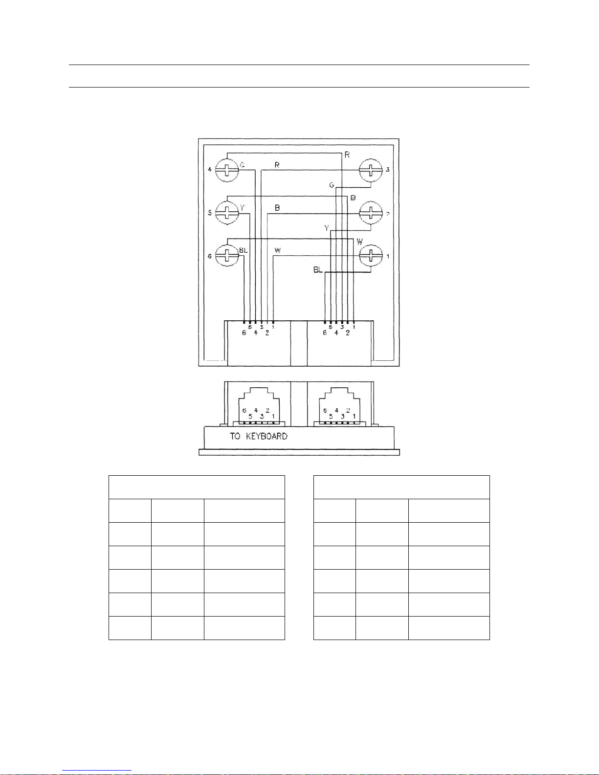
RJ11 TWO-WAY JUNCTION BOX
Drawing MG10075
TO HMXAT200
Keyboard RJ11 Connector HMXAT200 RJ11 Connector
Pin 1 White 12V Pin 1 White Power Ground
Pin 2 Black NC Pin 2 Black TX
Pin 3 Red TX Pin 3 Red Signal Ground
Pin 4 Green Signal Ground Pin 4 Green RX
Pin 5 Yellow RX Pin 5 Yellow NC
Pin 6 Blue Power Ground Pin 6 Blue 12V
Rev. 1.0 6 900.0688
9-Dec-05
Page 13
3.1 CONNECTING THE DEVICES, CONTINUED
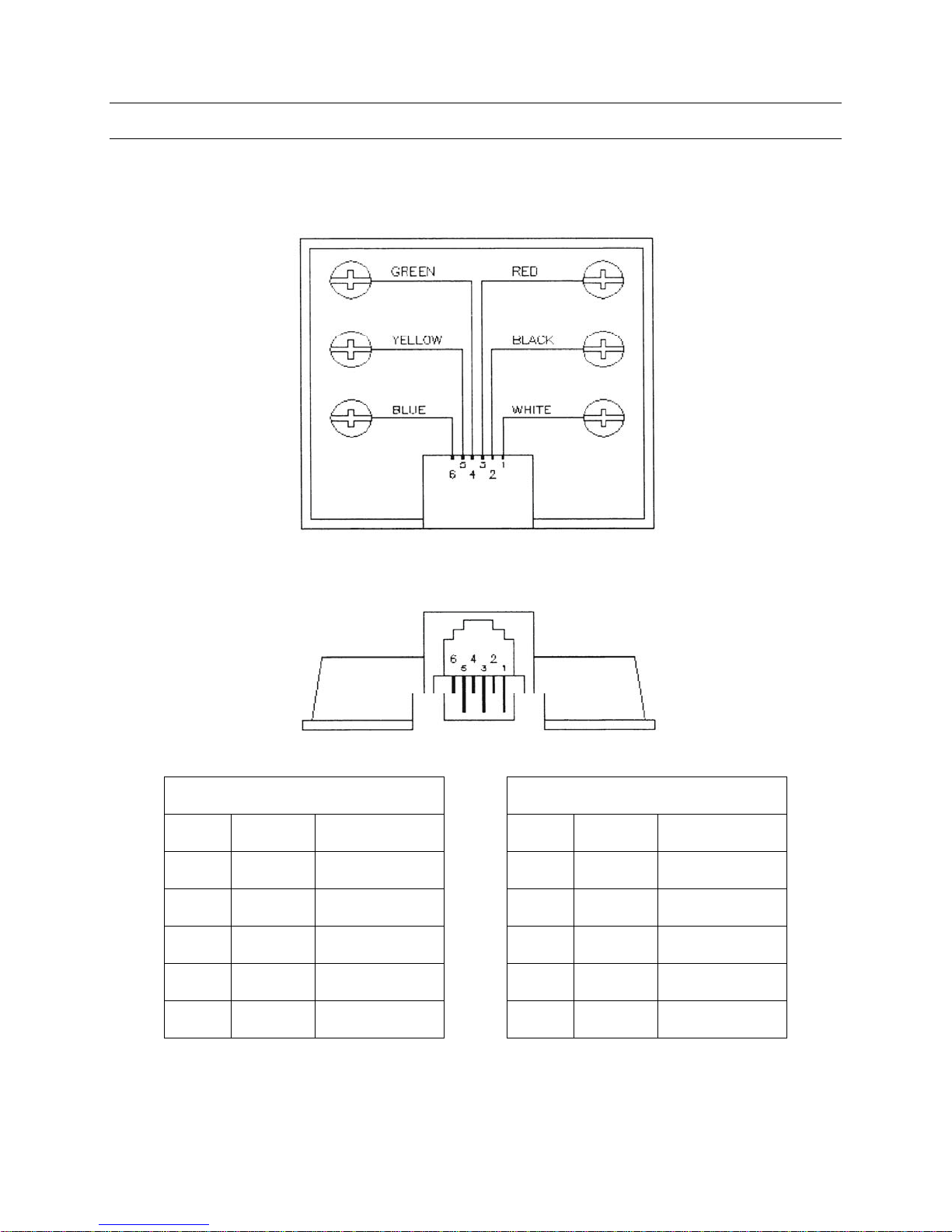
RJ12 TERMINAL BOX
PIN CONNECTIONS
Drawing MG10023
RJ12 D15
Pin 1 White 12V Pin 8 12V
Pin 2 Black NC NC
Pin 3 Red TX Pin 3 TX
Pin 4 Green Signal Ground Pin 5 Signal Ground
Pin 5 Yellow RX Pin 2 RX
Pin 6 Blue Power Ground Pin 15 Power Ground
Rev. 1.0 7 900.0688
9-Dec-05
Page 14

3.1 CONNECTING THE DEVICES, CONTINUED
E.M.C. COMPLIANCE - INSTALLATION REQUIREMENTS
The HEGS5300 keyboard, as supplied, includes a 1.5-meter standard interface cable.
The HEGS5300 is supplied as an O.E.M. component, therefore it is a mandatory
requirement to specify the installation parameters in order to comply with the European
Directives on E.M.C.
The HEGS5300 keyboards have been installed, tested and found to comply under the
following conditions:
1. With the standard lead attached to the System Controller.
2. With the standard lead attached to an approved telecommunications modem and
with the power requirements supplied by a CE approved Plug Pack.
3. With the standard lead attached to a Fiber Optic Transmitter and with the power
requirements supplied by a CE approved Plug Pack.
4. With a passive extension (not exceeding 50m total) using a cable and Shield Beads,
with the Shield Beads fitted adjacent to the connectors.
Note: It should be noted that any variation to the above conditions may not comply
with the European Directives on E.M.C. and therefore must be cleared with the
supplier before implementation.
4. Connect 12 VDC power to the CCTV control keyboards.
5. Interconnect the video subracks using the provided cables. Take care to ensure the
cables are installed as shown in the enclosed drawing for your configuration.
6. Connect the menu output of the HMXAT200 to the last
video input in the system
using an RG59 video patch cable with BNC connectors on both ends.
7. Connect all video inputs and outputs to the video subracks per the completed
worksheets. Note: If the switcher system is looping, a looping panel(s) is required
for each HMX32128 chassis in the system. If there are 64 or less video inputs, one
looping panel can be used. If there are more than 64 video inputs, two (2)
HMXBNC128 looping panels are required for each HMX32128 chassis. Looping
coax ribbon cables, MXLCM4, are required for connection between the looping
panel(s) and the HMX32128 chassis. One looping coax ribbon cable is required for
each set of eight (8) video inputs. Refer to the drawing provided with your system
for looping video configurations.
8. If the HMX4248 I/O module is installed on the switcher, refer to section 3.2 for
installation and setup details.
Rev. 1.0 8 900.0688
9-Dec-05
Page 15

3.1.1 PTE102 RS-232 Line Driver
The PTE102 module set containing the PTE102C and the PTE102K is a stand alone
communication module pair for extending the RS-232 range of either subracks or
keyboards in the Honeywell product line.
Designed to support MAX-1000 standard RJ12 connections to keyboards and subracks,
the PTE102 can be used with other RS-232 applications. The PTE102 provides a
convenient method for extending most RS-232 data communication.
The PTE102C unit is connected to the HMXAT200 Control Computer and can be
powered from either a 12V DC plug pack or from Port 3 or 4 of the HMXAT200. The
remote keyboard or subrack PTE102K is powered from an optional standard 12V DC
plug pack.
Connection Example
HEGSA002 ULTRAKey or
HEGS5300 Keyboard Controller
Rev. 1.0 9 900.0688
9-Dec-05
Page 16

3.2 HMX4248 I/O MODULE
The HMX4248 is an I/O (input/output) expander for the miniMAX subrack.
The unit features 24 alarm inputs that may be configured as either contact closure or
end-of-line resistor sensing (DIP switch selectable on the HMX128 controller card) and
eight relay outputs.
3.2.1 Installation
a. Install the HMX4248 on the rear of the HMX32128 subrack using the mounting
stand-off posts and screws supplied.
b. Connect the HMX4248 to the HMX128 using the supplied ribbon cable
(take care not to dislodge the HMX128 card when seating the connector).
c. Select the required operating mode on the HMX128.
DIP switch 3, position 4 – OFF = contact closure mode
DIP switch 3, position 4 - ON = end-of-line resistor mode
d. Connect the field cabling to the input/output connectors.
Inputs:
Maximum voltage is ±20V
Control Outputs:
Maximum current = 1 Amp
Maximum voltage = 50V
3.2.2 Operation
Contact Closure (CC) Mode
When configured in the CC mode, the HMX4248/HMX128 detects contact changes of
state according to the NO/NC setting as defined in the Alarm Input table in SETMAX.
End-Of-Line (EOL) Mode
When configured in the EOL mode, a setting of NC in SETMAX causes an alarm to
become active when the alarm loop becomes either open or short circuited (unsealed).
Conversely, in the NO mode, the alarm becomes active when the loop is in the “sealed”
position.
Rev. 1.0 10 900.0688
9-Dec-05
Page 17

SECTION 4:
4.1 POWERING UP THE MINIMAX
1. Remove the front cover(s) of the HMX32128 video subracks and remove the packing
cardboard from the subracks. Replace the front cover(s).
2. Connect the power cords from the video subracks (HMX32128) to the HMXPS9
power supply using the supplied cables.
3. Connect the power cord to the HMXAT200 and HMXPS9 and plug them into a good
earth grounded outlet.
4. Place the power switch on the front of the HMXPS9 Power Supply in the ON
position.
5. Check that all 8 amber indicator LEDs on the front of the HMXPS9 are illuminated (2
LEDs per output). An extinguished LED indicates a problem on the corresponding
output (1, 2, 3, or 4). Disconnect the corresponding power cable from the equipment
and check the device.
POWER
6. Remove the front cover from the HMXAT200 System Controller.
7. Depress the red power switch to turn the System Controller power on.
The System Controller will automatically load the default system configuration
from the hard-drive.
8. Camera number 1 will be displayed on Monitor number 1.
Rev. 1.0 11 900.0688
9-Dec-05
Page 18

SECTION 5:
HEGS5300
5.1 SETTING UP THE HEGS5300 KEYBOARD
HEGS5300 keyboards are setup using the keyboard keys. There are three (3)
user-defined settings. These are:
• Keyboard ID – valid ID’s 1 to 99. (Default = ID 1).
• Baud Rate – 19K2 or 9600. (Default = 19K2. Data format is fixed at 7 data bits,
1 stop bit, even parity).
• Joystick speed range – There are 2 ranges of pan/tilt speeds from the analogue
joystick. The default is a range of 5 speeds (0=STOP to 5=Maximum speed). The
alternative is a range of 26. As before 0=STOP, but the speeds generated are from A
(slowest) through to Z (fastest). Speed Z is equivalent to speed 5, in that it is
generated when the joystick is at its maximum pan or tilt position. This feature is
available when using MAX1000, version 4.27 or later.
To enter the SETUP MODE hold down the MENU
hand-side of the LCD) as the keyboard is powered up.
Note: If the keyboard has a custom overlay, the MENU key may be located in a different
position. Therefore, using the ½ key next to the LCD is always a preferred option.
Once in the setup mode, the LCD prompts the user to enter the required information
using the numeric keypad. Pressing the enter key (↵) or the ¾ key moves to the next
stage. Pressing the ½ key goes back to the previous setup screen.
When the keyboard ID, baud rate, and joystick speed range have been entered, the final
setup stage stores the settings and the joystick reference position. The keyboard should
be flat on the desk when pressing the enter key (↵) at this final stage to ensure the
joystick is zeroed. Setup information is stored in non-volatile memory so the settings will
be retained if the keyboard is unplugged.
key or the ½ key (to the left-
Rev. 1.0 12 900.0688
9-Dec-05
Page 19

SECTION 6:
SYSTEM TESTING
6.1 TESTING THE SYSTEM WITH THE DEFAULT CONFIGURATION
(RECOMMENDED)
Your miniMAX system computer has been loaded with a default configuration.
This configuration will provide switching of any camera to any monitor. It is
recommended that the system hardware be tested in this mode prior to editing the
system configuration using the SETMAX program. PTZ control is defined for camera
number 1 (set to address 1) for testing purposes.
1. To select a camera to a monitor;
Press the MON key, press the number of the monitor you require, and then press
the ENT (Enter) key.
2. After selecting the monitor, press the CAM key, press the number of the camera you
require, and then press the ENT (enter) key.
Further cameras can be selected to the same monitor by repeating step 2 (above), or by
using the up or down arrow keys
or
Rev. 1.0 13 900.0688
9-Dec-05
Page 20

SECTION 7:
INSTALLING SOFTWARE
7.1 INSTALLING THE SETMAX SOFTWARE ON YOUR PC
A CD-ROM is included in the documentation package. This CD-ROM contains the
Commissioning Manual, Operator’s Manual, the Quick Start Configuration Guide, and
the SETMAX for Windows editor software. The SETMAX software must be loaded onto
a PC or laptop in order to edit the default configuration. The SETMAX program requires
approximately 6 MB of space on the hard drive. If a CD-ROM is not available, please
contact Honeywell Technical Support and request SETMAX for Windows® on 3½-inch
diskettes.
Perform the following steps to install SETMAX for Windows® onto your PC or laptop:
1) Load the CD-ROM into the CD-ROM drive on your PC or laptop.
2) Select the Windows START button
3) Select R
Browse the CD directory and locate the Setup.exe file.
4) Select Setup.exe and click on the O
Follow the setup prompts.
The SETMAX software will be installed on your hard drive at the following location:
C:\Program Files\Setmax.
You may create a shortcut to Setmax.exe on your desktop if desired.
un.
pen button. Select OK in the RUN window.
Rev. 1.0 14 900.0688
9-Dec-05
Page 21

SECTION 8:
CONFIGURATION
8.1 EDITING AND LOADING THE CONFIGURATION
The documentation package includes two 3½ inch diskettes. The backup disk should
be safely stored in case there is a need to return to the factory default settings. The
system disk that is created during the configuration process provides a backup disk for
the site-configured software.
1. Insert the 3½-inch diskette labeled “MAX-1000 System Disk” into the floppy drive of
the PC (where the SETMAX for Windows® software has been installed).
2. Open the SETMAX editor software by selecting Setmax.exe (located on your hard
drive at: C:\Program Files\Setmax) or the designated icon on your desktop for
Setmax for Windows®).
3. Select F
displayed in a window on the PC. The files can be edited for your site configuration.
ile , Open , A: , Title.max. The default configuration files will be opened and
8.2 HARDWARE MAPPING
The subrack ID is setup using the HMX128 card. Since the miniMAX incorporates all of
its functionality via one subrack ID, it is necessary to map the hardware in each subrack
to “slot” numbers which are used when configuring SETMAX.
The hardware mappings are as follows:
a. Video Fail/Level Detection - The video fail/level detection is disabled by default to
prevent numerous alarms from video inputs that do not have video connected to
them. Enable this feature after all cameras are connected to the video inputs. To
enable video fail/level detection, enter the appropriate value (slot number) in the FSL
field of the video input table in SETMAX.
Physical Input
1-32 11
33-64 12
65-96 13
97-128 14
Slot
(FSL field in SETMAX)
Rev. 1.0 15 900.0688
9-Dec-05
Page 22

8.2 HARDWARE MAPPING, CONTINUED
b. Pan/tilt Control Ports
Physical Outputs on
HMX128 Control Card
(CSL field in SETMAX)
Slot
1 1
2 2
3 3
4 4
5 5
6 6
7 7
8 8
c. Text - The text is predefined in SETMAX.
Text
(TSL field in SETMAX)
Slot
Output Card 1 1-8
Output Card 2 9-16
Output Card 3 17-24
Output Card 4 25-32
d. Alarm Inputs - The alarm inputs only apply if the HMX4248 I/O Card is installed on
the rear of the switcher.
Alarm Input
(ASL field in SETMAX)
Slot
1-8 15
9-16 16
17-24 17
e. Contact Outputs - The contact outputs only apply if the HMX4248 I/O Card is
installed on the rear of the switcher.
Output #
(OSL field in SETMAX)
Slot
1-8 1
Rev. 1.0 16 900.0688
9-Dec-05
Page 23

8.3 CHANGING CAMERA TITLES
The miniMAX default camera titles can be easily changed using the SETMAX editor.
Select the “Video I
DESCRIPTION) to be changed and type in the new description.
nputs” tab. Use the mouse to select the camera title (DEVICE
Rev. 1.0 17 900.0688
9-Dec-05
Page 24

8.4 ADDING “PTZ CALLS”
PTZ call provides single key “call” of PTZ cameras and views (presets) defined against
any fixed camera. To define the PTZ call, simply enter the desired PTZ camera (to call)
and preset number in the ALTERNATE CAMERA NUMBER and ALTERNATE CAMERA
VIEW fields. In the example below, when camera 1 is selected, camera 10 with view 2
will be called when the “PTZ Call” key is pressed on the operator keyboard.
Rev. 1.0 18 900.0688
9-Dec-05
Page 25

8.5 ADDING PTZ CONTROL
In the default configuration, camera number 1 is the only camera configured as a PTZ
camera (PTZ control). The default PTZ address is set to 1. If there are other PTZ
cameras connected to the switcher, the video input table must be edited to define these
cameras. If camera number 1 is not a PTZ, control should be removed from this input.
1. With SETMAX running and A:/Title.max opened, select the Video I
a. Select the first camera to edit using either the mouse or the arrow keys.
b. Select the SOURCE CONTROL cell. Select the button that appears
(
) and four additional columns appear.
nputs tab.
Rev. 1.0 19 900.0688
9-Dec-05
Page 26

8.5 ADDING PTZ CONTROL, CONTINUED
2. Select the CONTROL ID cell for the camera to be edited. Enter the number of the
subrack (ID number set on the HMX128 Subrack Controller Module – first slot in the
HMX32128 subrack), where the PTZ data line will be connected. (This can be
different than where the video input is connected.)
3. Select the CONTROL SLOT cell and enter the number of the data port on the rear of
the video subrack that the PTZ data line for this camera will be connected to
(1 – 8).
4. Select the CONTROL OFFSET cell and enter the number of the address to be
assigned to that camera (1-16 per data port).
5. Select the AVAILABLE CONTROL cell. Select the
a. Select the desired control functions for this camera using the check boxes.
b. Select OK
c. Repeat the above steps for each PTZ camera.
button that appears.
Rev. 1.0 20 900.0688
9-Dec-05
Page 27

8.6 CHANGING MONITOR TITLES
The miniMAX default monitor titles can be easily changed using the SETMAX editor.
Select the “Video O
(DESCRIPTION TEXT) to be changed and type in the new description.
utputs” tab. Use the mouse to select the monitor title
Rev. 1.0 21 900.0688
9-Dec-05
Page 28

8.7 DEFINING LOGICAL CAMERA SELECTIONS
Logical Camera Selection provides an alternative method of selecting cameras whereby
a keyboard key is defined for each logical group name. Camera selection is made by
selecting the desired group, plus a numeric entry. For example, to select the first
camera in the “entrance” (which may be any camera number), the operator would select
<ENTRANCE> <1>.
Default logical groups are defined on MAX-1000 keyboards and in the system
configuration. To edit the name of a logical group, select the L
tab and type the new name for the logical group into the LOGICAL GROUP
DESCRIPTION field.
ogical Camera Selection
Rev. 1.0 22 900.0688
9-Dec-05
Page 29

8.7 DEFINING LOGICAL CAMERA SELECTIONS, CONTINUED
To define the cameras within that logical group, select the VIEW / EDIT GROUP cell
corresponding to the group to edit. A window will appear providing the required data
fields. The Selection Number is the numeric value to be entered from the keyboard to
call this camera. E.g. <ENTRANCE> <1>. The Primary Camera is the actual camera
number that will be displayed when this selection is made. If their camera is a PTZ, a
preset “view” number may be entered in the PRIMARY VIEW field.
8.8 DEFINING ALTERNATE CAMERA VIEWS
ALTERNATE cameras may be defined against any camera in a logical group. Once a
camera is selected using the logical selection process, the ALT key may be selected on
the keyboard to display other cameras that match that logical description. To define
alternate cameras, simply enter the camera and preset numbers (if applicable) in the
ALTERNATE CAMERA n and ALTERNATE VIEW n cells.
Rev. 1.0 23 900.0688
9-Dec-05
Page 30

8.9 OTHER SETTINGS
The miniMAX package is shipped preprogrammed with certain default settings for
various functions that are available. In the following pages you will find a description of
these functions and instructions on how to make changes to your system. The
illustration below will be helpful when reading through these instructions. This is an
illustration of the software when being viewed on a separate computer using the Setmax
Windows Configurator. The preprogrammed definitions that can be changed from this
window include, Alarm Monitor
definitions, Alarm Relay
Number definitions.
definitions, Alarm Camera definitions, Alarm Camera View
definitions, Logical Monitor Selection definitions, and Monitor
Rev. 1.0 24 900.0688
9-Dec-05
Page 31

8.9 OTHER SETTINGS, CONTINUED
8.9.1 Alarm Monitors
The alarm monitor(s) are monitors within the system which will automatically display
cameras that have been associated with external alarms that have been wired into the
system. When there are no alarms present these monitors may be used as call up
monitors in the same way that the other monitors are used. If multiple alarms occur, the
monitors cycle through all of the current alarms until they are cleared. By default there is
one alarm monitor defined. The monitor number is 8.
If you do not have a monitor 8, but you do have alarms, you will need to define which
monitor you want to use for the alarm monitor. You may change that number by going
into the sequence tables. These tables are used by the system to determine various
parameters that you would like to use for your specific location.
As you will soon see, the sequence tables allow you to easily tailor the powerful features
of the miniMAX for many applications. Looking at the sequence tables on line 20, you
will see that the description text is Alarm Monitors. Under column 1 you will see the
number 8. Line 20 will list all of the alarm monitors you wish to use. Column 1 indicates
that the monitor number underneath it is the first alarm monitor. Likewise column 2
would have the second, column 3 the third, etc. You may have multiple alarm monitors,
one alarm monitor, or no alarm monitors. It is important to remember that you do not
skip columns when redefining these monitors.
Let’s say that we would rather use monitor 3 for the alarm monitor instead of monitor 8.
We would simply go to line 20 (Alarm Monitors) under column 1 (the first alarm monitor)
and change the 8 to a 3.
Now we decide that we want 2 monitors to display alarms, monitor 3 and monitor 5.
Once again we would go into the sequence table to line 20 (Alarm Monitors) and under
column 1 (the first alarm monitor) we would put the number 3 for monitor 3 and under
column 2 (the second alarm monitor) we would put 5 for monitor 5.
8.9.2 Alarm Cameras
Alarm cameras are cameras that are switched to the alarm monitors when alarms are
triggered. The alarms, defined in the alarm input table, are numbered. Once again
looking in the sequence tables on line 21 you will see the description as Alarm Cameras.
The default programming switches the same camera number to the alarm monitors as
the alarm number. For example alarm number 1 pulls up camera 1, alarm 2 camera 2,
etc. To modify the camera being switched, you simply go under the column number
which is the same as the alarm number, and put the camera number you want to be
displayed when that alarm is activated.
For instance, we want to change the camera number for alarm number 7 from camera 7
to camera 42. We would go to line 21 (Alarm Cameras) and then scroll over to column 7
(the alarm number) and put the number 42 (the camera we want to call up) in that
column.
Rev. 1.0 25 900.0688
9-Dec-05
Page 32

8.9 OTHER SETTINGS, CONTINUED
8.9.3 Alarm Camera Presets
If you are using a PTZ you can call the PTZ to a preset view by placing the view number
that you want to call right under the camera number. This is line 22 with the description
“Alarm Camera Views.” Since there is no way of knowing what, if any, cameras are PTZ
cameras there have been no views preprogrammed in the miniMAX package.
8.9.4 Alarm Relay Outputs
You may take the alarm response a step further by activating control output relays
against each alarm. Default alarm relays are programmed against each of the possible
alarms. These preprogrammed relay outputs along with the cameras and their
associated alarms are shown in Table 1.
Table 1. Default Alarm, Camera, and Relay
Programming
Alarm Number Camera Number Relay Number
1 1 1
2 2 1
3 3 1
4 4 1
5 5 2
6 6 2
7 7 2
8 8 2
9 9 3
10 10 3
11 11 3
12 12 3
13 13 4
14 14 4
15 15 4
16 16 4
17 17 5
18 18 5
19 19 5
20 20 5
21 21 6
22 22 6
23 23 6
24 24 6
25 25 9
Rev. 1.0 26 900.0688
9-Dec-05
Page 33

8.9 OTHER SETTINGS, CONTINUED
Table 1. Default Alarm, Camera, and Relay Programming,
Alarm Number Camera Number Relay Number
26 26 9
27 27 9
28 28 9
29 29 10
30 30 10
31 31 10
32 32 10
33 33 11
34 34 11
35 35 11
36 36 11
37 37 12
38 38 12
39 39 12
40 40 12
41 41 13
42 42 13
43 43 13
44 44 13
45 45 14
46 46 14
47 47 14
48 48 14
49 49 17
50 50 17
51 51 17
52 52 17
53 53 18
54 54 18
55 55 18
56 56 18
57 57 19
58 58 19
59 59 19
60 60 19
61 61 20
62 62 20
continued
Rev. 1.0 27 900.0688
9-Dec-05
Page 34

8.9 OTHER SETTINGS, CONTINUED
Table 1. Default Alarm, Camera, and Relay
Programming, continued
Alarm Number Camera Number Relay Number
63 63 20
64 64 20
65 65 21
66 66 21
67 67 21
68 68 21
69 69 22
70 70 22
71 71 22
72 72 22
Additional relays are preprogrammed for the following functions
Functions Relay Number
Door Relay 7
Camera Fail Relay 8
Auxiliary Relay 1 15
Auxiliary Relay 2 16
Auxiliary Relay 3 23
Auxiliary Relay 4 24
Rev. 1.0 28 900.0688
9-Dec-05
Page 35

8.9 OTHER SETTINGS, CONTINUED
8.9.5 Logical Monitor Selection
Logical monitor selection allows the operator to select the monitor he wishes to work
with by a single key press. It is particularly effective where multiple operator stations are
being used. In the example below, the operator work station has 3 monitors in front of
the operator and 4 monitors behind the console. From the physical appearance of this
station you may assume that the monitor numbers start at the top left corner and
increment from top to bottom, left to right. If the system were set up this way the
monitors directly in front of the operator would be monitors 5, 6, and 7.
Since the operator will be more likely to work with these monitors they can be referred to
as “Monitor A” “Monitor B” and “Monitor C.” Using logical monitor selection, the
operator can quickly switch from one monitor to the next using a single key stroke.
Rev. 1.0 29 900.0688
9-Dec-05
Page 36

8.9 OTHER SETTINGS, CONTINUED
If we take this a step farther the top 4 monitors can be defined as “Monitor D”, “Monitor
E”, “Monitor F”, and “Monitor G.” If you add another station to the system and duplicate
this setup you can still use the same logical monitor selection for it. In this manner, the
operator does not have to know what the monitor number is at the station he is currently
working on, he only needs to use the same Mon A, B, C, D, E, F, or G keys. The default
logical monitor selection is programmed for 1 keyboard and is programmed for monitors
1 through 8. To edit these monitor numbers you look at the sequence tables on lines 30
through 37. With the logical monitor selection the columns identify which keyboard ID
you are programming. To edit the tables for the example described above we would do
the following:
On line 30 (Mon A) under column 1 (keyboard ID 1) we would enter 5 (the actual monitor number).
On line 31 (Mon B) under column 1 (keyboard ID 1) we would enter 6 (the actual monitor number).
On line 32 (Mon C) under column 1 (keyboard ID 1) we would enter 7 (the actual monitor number).
On line 33 (Mon D) under column 1 (keyboard ID 1) we would enter 1 (the actual monitor number).
On line 34 (Mon E) under column 1 (keyboard ID 1) we would enter 2 (the actual monitor number).
On line 35 (Mon F) under column 1 (keyboard ID 1) we would enter 3 (the actual monitor number).
On line 36 (Mon G) under column 1 (keyboard ID 1) we would enter 4 (the actual monitor number).
If we expanded this system to the second operator/keyboard we would add the
following:
On line 30 (Mon A) under column 2 (keyboard ID 2) we would enter 12 (the actual monitor number).
On line 31 (Mon B) under column 2 (keyboard ID 2) we would enter 13 (the actual monitor number).
On line 32 (Mon C) under column 2 (keyboard ID 2) we would enter 14 (the actual monitor number).
On line 33 (Mon D) under column 2 (keyboard ID 2) we would enter 8 (the actual monitor number).
On line 34 (Mon E) under column 2 (keyboard ID 2) we would enter 9 (the actual monitor number).
On line 35 (Mon F) under column 2 (keyboard ID 2) we would enter 10 (the actual monitor number).
On line 36 (Mon G) under column 2 (keyboard ID 2) we would enter 11 (the actual monitor number).
8.10 SAVE YOUR CHANGES
To save changes to the floppy disk:
1. Select F
2. Select Sav
ile
e All.
Rev. 1.0 30 900.0688
9-Dec-05
Page 37

8.11 LOADING THE CHANGES INTO THE HMXAT200 CONTROLLER
To load the revised configuration into the HMXAT200 System Controller, perform the
following steps.
1. Remove the floppy disk (with the saved changes) from your PC and place it into the
floppy drive of the HMXAT200 System Controller.
2. Depress the green reset button (behind the front cover) on the HMXAT200. This will
automatically copy the updated configuration files to the hard-drive of the
HMXAT200.
3. Wait for the LED on the floppy disk drive to extinguish before proceeding.
4. Remove the floppy disk from the drive and depress the green reset button once
again to re-boot the HMXAT200 System Controller to the new configuration.
Note: The system will not run
5. Store the floppy disk in a safe place.
The miniMAX system is now operational. If you are starting the system for the first time,
the time and date will need to be set to your local time.
with the floppy disk still in the floppy-drive.
Rev. 1.0 31 900.0688
9-Dec-05
Page 38

SECTION 9:
SETUP
9.1 SETTING THE SYSTEM DATE AND TIME
To set the date and time, you must access the MENU SYSTEM.
9.1.1 Accessing the Menu System
Press the key on the CCTV keyboard. The main menu is displayed on the
currently selected monitor. If a monitor is not currently selected, the menu will appear
on the last selected monitor.
Notes:
• Access may be denied to some operators.
• The Menu System must be declared for use at the time of commissioning.
• Only one operator (i.e. CCTV keyboard) can have access to the Menu System at any
one time.
• If more than one CCTV keyboard is selecting the monitor, the Menu System
CANNOT be accessed. Move to another monitor prior to using the Menu System.
• If the monitor is running a scan sequence, then selecting the Menu System will
HALT the scan sequence. Exiting the Menu System will NOT restart the scan
sequence, this must be done manually.
9.1.2 Exiting the Menu System
To exit the MENU SYSTEM, press again. The menu display is replaced by the
original camera selection. You can exit from the MENU SYSTEM at any time, from any
menu level.
9.1.3 Making Selections from the Menu
When the menu is displayed move the highlighting bar to the required line.
Pulling the joystick towards you will move down the
menu to the next line.
Rev. 1.0 32 900.0688
9-Dec-05
Pushing the joystick away from you will move up the
menu to the previous line.
Page 39

9.1 SETTING THE SYSTEM DATE AND TIME, CONTINUED
By making several joystick actions you can move the highlighting bar to the desired line,
ready for selection.
Pushing the joystick RIGHT will select that
highlighted line and display the next corresponding
Menu Level or Entry Window.
Pushing the joystick LEFT will remove your current
Menu and return you to the previous Menu Level.
Note: The
move up and down the Menu. Pressing the
and keys on the SELECTION PAD of the CCTV keyboard will also
key will select the
highlighted line in the Menu and display the next corresponding Menu Level or
Entry Window.
The current time and date information can be displayed on all video channels or
selected video output channels.
Although the system clock is battery backed to prevent loss of time/date during power
failures, it is sometimes necessary to re-set the current time and date.
From the main menu, highlight and select the item, 'Set Clock Current Time/Date'.
Note: If you do not have the correct access privileges, the message. 'ACCESS DENIED',
will be flashed on the monitor.
Rev. 1.0 33 900.0688
9-Dec-05
Page 40

9.1 SETTING THE SYSTEM DATE AND TIME, CONTINUED
MAX-1000 v4.**
SIGN-ON Keyboard Operators
SIGN-OFF Keyboard Operators
ENABLE/DISABLE Video Inputs
LOCK/UNLOCK Video Input Controls
LOCK/UNLOCK Video Output Channels
ENABLE/DISABLE Alarm Inputs
SET CLOCK Current Time/Date
CHANGE PIN Number
STATUS Information
SYSTEM Configuration
9.1.4 Set Current Time/Date
From this menu, you can choose to reset either of the following two parameters:
• Enter new TIME, or
• Enter new DATE
Set Current Time/Date
Enter NEW Time
Enter NEW Date
Enter New Time
When selected, the entry window displays the current time known to the system clock.
Changes are made by simply overwriting the displayed time.
MAX-1000 v4.**
SIGN-ON Keyboard Operators
SIGN-OFF Keyboard Operators
ENABLE/DISABLE Video Inputs
LOCK/UNLOCK Video Input Controls
LOCK/UNLOCK Video Output Channels
ENABLE/DISABLE Alarm Inputs
SET CLOCK Current Time/Date
CHANGE PIN Number
STATUS Information
SYSTEM Configuration
Set Current Time/Date
Enter NEW Time
Enter NEW Date
Enter NEW Time: as (HHMM)
1430
Rev. 1.0 34 900.0688
9-Dec-05
Page 41

9.1 SETTING THE SYSTEM DATE AND TIME, CONTINUED
The time is presented as a four digit number (HHMM) where:
HH = hours in two digits (00 Q 23)
MM = minutes in two digits (00 Q 59)
Type in the new time in the same four-digit format. When you have finished editing,
press the
onto all video output channels
Enter New Date
When selected, an entry window displays the current date known to the system clock.
Changes are made by overwriting the displayed date.
SIGN-ON Keyboard Operators
SIGN-OFF Keyboard Operators
ENABLE/DISABLE Video Inputs
LOCK/UNLOCK Video Input Controls
LOCK/UNLOCK Video Output Channels
ENABLE/DISABLE Alarm Inputs
SET CLOCK Current Time/Date
CHANGE PIN Number
STATUS Information
SYSTEM Configuration
key. The new time (if formatted correctly) will be instantly updated
MAX-1000 v4.**
Set Current Time/Date
Enter NEW Time
Enter NEW Date
Enter NEW Date: as DDMMYY
140199
The date is presented as a six digit number (DDMMYY) where:
DD = day of the month in two digits (01 Q 31)
MM = month of the year in two digits (01 Q 12)
YY = year in two digits (00 Q 99)
Type in the new date in the same six-digit format. When you have finished entering the
new date, press the
key. The new date (if formatted correctly) will be
instantly updated onto all video outputs.
Rev. 1.0 35 900.0688
9-Dec-05
Page 42

SECTION 10:
SETTING UP DOMES
10.1 HONEYWELL KD6/HD6 SERIES DOMES
To access the dome setup menus, the dome must be operational and you must be able
to control the dome (pan, tilt, etc.). The firmware revision level in the HMX128 card
(MX308 chip) must be V1.06 or above.
The following equipment is required:
• MiniMAX system
• Dome to be configured
• QWERTY keyboard
• Two monitors
ULTRAKey or
HEGS5300 KEYBOARD
Procedure:
1. Log the QWERTY keyboard to the Operator Monitor.
2. Select the dome being configured to the Operator Monitor.
3. Press Ctrl F9 on the QWERTY keyboard.
4. Select the required setup menu displayed on the Test Monitor.
5. Select the required option from the menu displayed on the Operator monitor.
6. Make the required changes.
7. Press Esc on the QWERTY keyboard to exit the configuration menu on the Operator
Monitor.
8. Press Ctrl F9 on the QWERTY keyboard to exit the Setup menu on the Test Monitor.
9. Log off the QWERTY keyboard. Operation returns to normal.
Rev. 1.0 36 900.0688
9-Dec-05
Page 43

11.1 OVERVIEW
Worksheets are provided to assist the installer and software programmer in configuring
the switcher system. Honeywell recommends planning the installation and filling out the
worksheets prior to connecting any cameras or monitors to the switcher chassis.
SECTION 11:
WORKSHEETS
Rev. 1.0 37 900.0688
9-Dec-05
Page 44

Honeywell Video Systems (Head Office)
2700 Blankenbaker Pkwy, Suite 150
Louisville, KY 40299
www.honeywellvideo.com
TEL+1-800-796–2288
Honeywell Security Australia Pty Ltd.
Unit 5, Riverside Centre, 24-28 River Road West
Parramatta, NSW 2150, Australia
www.ademco.com.au
TEL +61-2-8837-9300
Honeywell Security Asia Pacific
Flat A, 16/F, CDW Building, 388 Castle Peak Road
Tsuen Wan, N.T., Hong Kong
www.security.honeywell.com/hk
TEL +852-2405-2323
Honeywell Security France
Parc Gutenberg, 8, Voie La Cardon
91120, Palaiseau, France
www.honeywell-security.fr
TEL +33-01-64-53-80-40
Honeywell Security Italia SpA
Via della Resistenza 53/59, 20090 Buccinasco
Milan, Italy
www.security.honeywell.com/it
TEL +39-02-457-1791
Honeywell Security Espana
Calle Vivero, 5, 28040
Madrid, Spain
www.security.honeywell.com/es
TEL +34-91-102-5900
Honeywell Video Systems UK Ltd.
Aston Fields Road, Whitehouse Ind Est
Runcorn, Cheshire, WA7 3DL, UK
www.honeywellvideo.com
TEL +44-1928-754-030
Honeywell Security South Africa
Unit 6 Galaxy Park, Galaxy Avenue, Linbro
Business Park
P.O. Box 59904, Kengray, 2100, South Africa
www.honeywell.co.za
TEL +27-11-574-2500
Honeywell Security Germany
Großenbaumer Weg 8
40472 Düsseldorf, Germany
www.honeywell-security.de
TEL +49-211-41-50-90
Honeywell Security Poland
Chmielewskiego 22a, 70-028
Szczecin, Polska
www.ultrak.pl
TEL +48-91-485-40-60
Honeywell Security Czech Republic
Havránkova 33, Brno
Dolní Heršpice, 619 00, Czech Republic
www.olympo.cz
TEL +420-543-558-111
Honeywell Video Systems Northern Europe
Netwerk 121
1446 TR Purmerend, Netherlands
www.SecurityHouse.nl
TEL +31-299-410-200
Honeywell Security Slovakia Republic
Vajnorskà 142, 83104 Bratislava
Slovakia
www.olympo.sk
TEL +421-2-444-54-660
Video Systems
www.honeywellvideo.com
1-800-796-CCTV (North America only)
© 2004 Honeywell International Inc.
All rights reserved. No part of this publication may be reproduced by any means without written permission from
Honeywell Video Systems. The information in this publication is believed to be accurate in all respects. However,
Honeywell Video Systems cannot assume responsibility for any consequences resulting from the use thereof. The
information contained herein is subject to change without notice. Revisions or new editions to this publication may
be issued to incorporate such changes.
 Loading...