

Honeywell LEGIC-Leser, mifare-Leser, proX1-Leser Installation And Operating Instructions Manual
Page 1
Montage- und Bedienungsanleitung
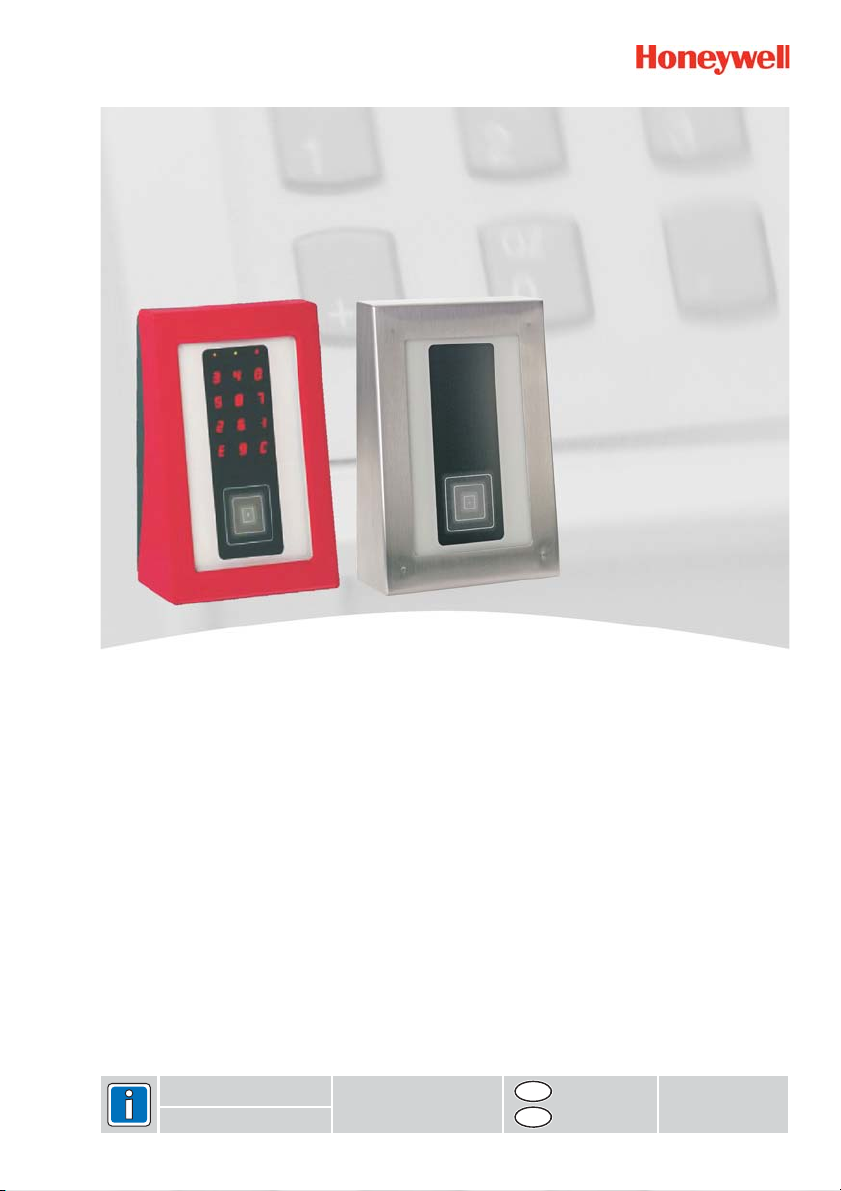
Leser mit Scramble Tastatur
proX1-Leser Art.-Nr. 026445 / 026445.10
mifare-Leser Art.-Nr. 026446
LEGIC-Leser Art.-Nr. 026447
P31061-45-002-01
2010-11-23
D
GB
Seite 1-8
Seite 9-16
Änderungen
vorbehalten
Page 2

Montage-Anschluss-Anleitung Leser mit Scramble Tastatur2
Inhaltsverzeichnis Seite
1. Anwendung.................................................................................................................................3
2. Leser-Varianten ..........................................................................................................................3
3. Funktionsbeschreibung ............................................................................................................3
Montage
4. ......................................................................................................................................4
4.1 ......................................................................................................................4
Abmessungen
4.2 Montagerichtlinien................................................................................................................4
5. Anschlussplan............................................................................................................................5
5.1 Schnittstelle..........................................................................................................................5
6. Inbetriebnahme ..........................................................................................................................6
6.1 Einführung............................................................................................................................6
6.2 Adresseinstellung.................................................................................................................6
6.3 Parameter ............................................................................................................................6
6.4 LED-Anzeuige......................................................................................................................6
7. Bedienung...................................................................................................................................7
7.1 Aktivierung der Tastatur .......................................................................................................7
7.2 Schalt-/Steuervorgang .........................................................................................................7
7.3 Makroauslösung...................................................................................................................7
8. Reinigung und Pflege ................................................................................................................7
9. Technische Daten.......................................................................................................................8
Sicherheitshinweise
Lesen Sie die Anleitung sorgfältig und vollständig durch, bevor Sie das Gerät installieren und in
Betrieb nehmen. Sie erhalten wichtige Hinweise zur Montage, Programmierung und Bedienung.
Das Gerät ist nach dem neuesten Stand der Technik gebaut. Benutzen Sie das Gerät nur:
- bestimmungsgemäß und
- in technisch einwandfreiem und ordnungsgemäß eingebautem Zustand
- gemäß den technischen Daten.
Der Hersteller haftet nicht für Schäden,die durcheinen bestimmungswidrigen Gebrauch verursacht werden.
Installation, Programmierung sowie Wartungs- und Reparaturarbeiten dürfen nur durch autorisiertes
Fachpersonal durchgeführt werden.
Löt- und Anschlussarbeiten innerhalb der gesamten Anlage sind nur im spannungslosen Zustand
vorzunehmen.
Lötarbeiten dürfen nur mit einem temperaturgeregelten, vom Netz galvanisch getrennten Lötkolben
vorgenommen werden.
VDE-Sicherheitsvorschriften sowie die Vorschriften des örtlichen EVU sind zu beachten.
Die Geräte dürfen nicht in explosionsgefährdeter Umgebung oder in Räumen mit metallund kunststoffzersetzenden Dämpfen eingesetzt werden.
Page 3

Montage-Anschluss-Anleitung Leser mit Scramble Tastatur 3
1. Anwendung
Die Leser mit Scramble Tastatur werden in Bereichen eingesetzt, in denen hochsichere Zutrittskontrolle mit erhöhten Sicherheitsanforderungen an die Kombination RFID - Transponder plus zusätzlicher persönlicher PIN gefordert sind.
Der Leser ist verfügbar mit drei unterschiedlichen RFID-Identifikationstechniken (Radio Frequency
Identification): LEGIC / mifare / proX1.
Die Tastenanordnung der vandalismussicheren PIN-Code-Tastatur arbeitet nach dem Zufallsprinzip. Nach jeder Aktivierung wird die zufällige Tastenbelegung "gescrambelt" = "verwürfelt" und dann
angezeigt. Die Leuchtflächen sind gleichzeitig Tastenflächen. Solange die Ziffernanzeige aktiviert
ist, kann der gewünschte PIN eingegeben werden. Im "Stand By" Zustand sind durch das "Dark
Design" weder Tasten noch Ziffern sichtbar.
Leistungsmerkmale
!
Unterschiedliche RFID-Identifikationstechniken kombiniert mit einer nach dem Zufallsprinzip
verwürfelt dargestellten PIN-Code Tastatur
!
Keine beweglichen Tasten / kein Verschleiß durch den Einsatz von kapazitiver Tastensensorik
!
vandalensichere und schlagfeste Glasfront
!
im nicht aktiven Zustand keine Tastatur sichtbar.
!
drei Leuchtfelder zur Statusanzeige (LEDs, grün, gelb und rot) und eine Hupe
!
großer Eingangsspannungsbereich (8 bis 30 V DC)
!
proX1-Leser auch mit abschließbarem Edelstahlblechgehäuse verfügbar
2. Leser-Varianten
Art.-Nr. 026445 = proX1-Leser mit Scramble Tastatur
Art.-Nr. 026445.10 = proX1-Leser mit Scramble Tastatur, Edelstahlgehäuse abschließbar
Art.-Nr. 026446 = mifare-Leser mit Scramble Tastatur
Art.-Nr. 026447 = LEGIC-Leser mit Scramble Tastatur
3. Funktionsbeschreibung
Die Leser sind für die berührungslose Identifizierung von Transpondern (
ID-Chipkarten Funktionsausführung
eine Kombination aus Transponder und PIN-Code hergestellt werden. Die Tastenanordnung
arbeitet nach dem Zufallsprinzip. Nach jeder Aktivierung wird die zufällige Tastenbelegung
"gescrambelt" = "verwürfelt" und dann angezeigt. Daher kann aus der Tastreihenfolge kein
Rückschluss auf die eingegebene PIN gezogen werden. Die Leuchtflächen sind auch Tastenflächen.
Um einen Transponder zu lesen, sendet der Leser ein elektromagnetisches Feld aus. Sobald sich
ein Transponder in diesem Feld befindet, sendet dieser Daten im "Energiefeld" zum Leser zurück.
Jeder Transponder ist ein Unikat.
Der übertragene Code wird zusammen mit der persönlichen PIN vom Leser so aufbereitet, dass
die Zutrittskontroll-Zentrale (ZKZ) die weitere Bearbeitung übernehmen kann, z.B. Schalt- und
Steuerfunktionen.
) bestimmt. Bei dem Leser mit Scramble Tastatur muss für eine
Informationsträgern, z.B.
Page 4
4
4. Montage
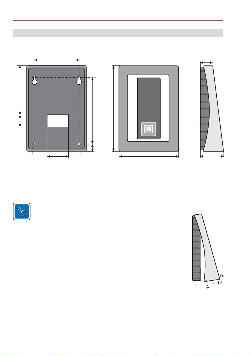
4.1 Abmessungen (in mm)
Montage-Anschluss-Anleitung Leser mit Scramble Tastatur
110
30
104
Kabeleinführung
50
157
23
210
140
35
75
4.2 Montagerichtlinien
Der Leser mit Kunststoffgehäuse ist nur für den Innenbereich geeignet. Der Leser mit Edelstahlgehäuse kann auch im geschützten Außenbereich eingesetzt werden. Die Montage kann
direkt an der Wand oder über einer "Standard-Unterputz-Dose" (DIN) erfolgen. Die Elektronikeinheit ist in das Gehäuseoberteil eingelegt und verschraubt.
Bei einem Montageuntergrund aus Metall kann die Reichweite etwas geringer sein als
bei einem nichtmetallischen Untergrund.
Um den Leser gut bedienen und ablesen zu können, sollte er in einer
Höhe von 130 bis 140 cm
vom Fußboden montiert werden.
Zur Montage werden die beiden Befestigungsschrauben unten gelöst und
heraus gedreht. Danach das
oben abheben.
Im Gehäuseboden sind für die Wandbefestigung oben zwei
Bohrungen mit Langloch und unten zwei Bohrungen jeweils mit
einem Lochabstand von 104 mm vorhanden.
Für eine sichere Befestigung sollten die Schrauben dem
Montageuntergrund angepasst sein.
- In Mauerwerk mit Dübel S6: z.B. Halbrund-Holzschraube mit Schlitz 3,5 x 60 mm
- In Holz, je nach Sorte : Halbrund-Holzschraube mit Schlitz 3,5 x 45 bis 3,5 x 60 mm
- In Metall: Zylinderkopfschraube mit Unterlegscheibe
Zur sicheren Befestigung können bei Bedarf die beiden unteren Montagebohrungen verwendet
werden (siehe 4.1). Die Schraubenlänge muss ebenfalls dem Montageuntergrund angepasst
werden. Bei der Montage sollte das Anschlusskabel nach Möglichkeit von hinten durch ein Leerrohr
mit genügend Kabelreserve zugeführt werden.
Gehäuseoberteil unten ausschwenken und nach
2x
M3 x 30 mm (min.)
Page 5
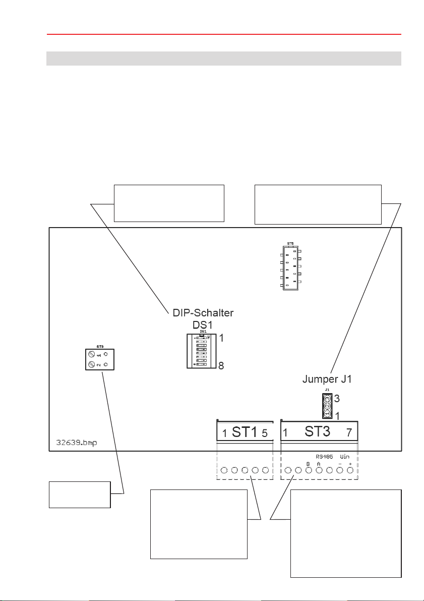
5. Anschlussplan
5.1 Schnittstelle
5Montage-Anschluss-Anleitung Leser mit Scramble Tastatur
Der Leser ist mit einer bidirektionaler Schnittstelle mit Modulbus-Protokoll (ACS-8, IK3)
ausgestattet.
Der Leser kann bis zu 1200 m abgesetzt werden.AlsAnschlusskabel wird Cat 5 empfohlen.
Ist der Leser der letzte Teilnehmer auf dem RS-485 Modulbus, muss vor dem Leser ein Verteiler mit
einem 120 Abschlusswiderstand (von A nach B) installiert werden der Jumper J1 muss zwischen
J1-J2 gebrückt sein (120 Abschlusswiderstand)
Weitere Informationen entnehmen Sie bitte der jeweiligen Beschreibung der Zutrittskontroll-Zentrale.
W
W
DS1
1 - 5 Leseradresse 0 - 31
6 - 8 nicht belegt
RS-485
oder
Jumper BUS Abschluss
J1-J2 gebrückt:
J2-J3 gebrückt: abgeschaltet
³
120 W
ST9
Alarmkontakt
ST1 (Ausgang - hier
nicht verwendet)
1+2: Masse
3: Ub 10 V - 30 V DC
4: I2C SCL
5: I2C SDA
ST3 (Eingang)
1: ohne Funktion
2:
ohne Funktion
3: B (RS 485), D*
4: A (RS-485), D
5: intern belegt
6: -Ub (Masse für Stromver-
7: +Ub (10 V - 30 V DC)
-
sorgung + RS-485-BUS)
Page 6

6 Montage-Anschluss-Anleitung Leser mit Scramble Tastatur
6 Inbetriebnahme
6.1 Einführung
Jeder am RS-485-Bus betriebene Leser muss mit einer versehen werden. Eine
Plausibilitätsprüfung
im System verhindert, dass Adressen mehrfach belegt werden können.
Möglicher Adressbereich: abhängig von der verwendeten Zutrittskontroll-Zentrale (ZKZ) .
Die Zuweisung der Adressen erfolgt über die DIP-Schalter 1 - 5.
Eine Änderung der DIP-Schaltereinstellung wird erst nach dem Anlegen der Betriebsspannung wirksam. Falls Sie die Einstellung im laufenden Betrieb ändern, unterbrechen
Sie anschließend kurzzeitig die Betriebsspannung.
6.2 Adresseinstellung
Jeder am RS-485-Bus betriebene Leser muss mit einer versehen werden. Mit
den DIP-Schaltern 1 bis 5 können die Leseradressen 0 bis 31 eingestellt werden. Achten Sie
darauf, dass keine Adresse mehrfach vergeben wird.
eigenen Adresse
eigenen Adresse
ON
ON
8
7
6
5
4
Adresse
3
2
1
Betriebsart
keine Funktion
16
8
4
2
1
Wertigkeit
Beispiel: Adresse 5
6.3 Parameter
Weitere Parameter werden über die ZKZ programmiert und sind somit anwendungsabhängig.
Dabei kommen je nach Anbindung an eine Zutrittkontrolle die beiden Programme IQNetEdit/
IQ MultiAccess oder bei
Anbindung an eine EMZ das jeweils zugehörige Programm WINFEM zur
Anwendung.
Bei der Funktionsweise ist immer PIN plus Karte einzustellen.
6.4 LED-Anzeige
Die LEDs des Lesers und die Funktion der Hupe werden von der ZKZ angesteuert. Abhängig von der
eingesetzten ZKZ sind die Funktionen festgelegt oder können über die Programmierung definiert
werden.
gelb grün rot
Page 7

7. Bedienung
7.1 Aktivierung der Tastatur
Die Hintergrundbeleuchtung für die Tastatur wird durch
den Transponder (ID-Karte) aktiviert.
Bei jeder Aktivierung wird gleichzeitig die Tastenbelegung
neu gescrambelt (verwürfelt).
7.2 Schalt-/Steuervorgang
1. Transponder (Karte) vor den Leser halten.
Damit wird die Tastatur aktiviert.
3 4 8
5 8
7
2 6 1
9
EC
7Montage-Anschluss-Anleitung Leser mit Scramble Tastatur
2. PIN-Code eingeben. Lösen Sie dabei den Finger
nach jeder Eingabe von der Tastaturoberfläche.
3. Transponder (Karte) nochmals vor den Leser halten.
Damit wird der Schalt-/Steuervorgang ausgelöst.
Der Transponder sollte
etwa mittig in dieses Feld
gehalten werden.
X
7.3 Makroauslösung
Grundsätzlich ist die Tastatur auch geeignet zur Auslösung von Makros, die in der ZutrittskontrollZentrale (ZKZ) hinterlegt sind.
Auf Grund der hohen Sicherheitsanforderungen und der daraus resultierenden komplexen
Bedienvorgänge wird jedoch empfohlen, diese Funktion nicht zu verwenden.
Falls die Makroauslösung doch verwendet werden soll, beachten Sie bitte die Dokumentation zu
IQ MultiAccess mit dem Titel "Weiterführende Funktionen" (P32205-46-000-xx).
8. Reinigung und Pflege
Gehäuse und Tastatur:
Das Gehäuse und die Tastatur können bei Bedarf mit einem weichen Tuch gereinigt werden.
Bei starker Verschmutzung können Sie ein mit Wasser angefeuchtetes Tuch benutzen .
Verwenden Sie keine Reinigungsmittel, Scheuermittel oder Lösungsmittel wie
Spiritus, Alkohol oder Benzin!
Page 8

8
Montage-Anschluss-Anleitung Leser mit Scramble Tastatur
9. Technische Daten
Betriebsnennspannung 12 V DC/24 V DC
Betriebsspannungsbereich 10 V bis 30 V DC
Stromaufnahme max. 600 mA
Leistungsaufnahme max. 6 W
Montageuntergrund beliebig, auch auf Metall
Übertragungsreichweite
- proX1 (125 kHz) / LEGIC max. 4,5 cm bei ID-Karten
- mifare
- Schlüsselanhänger, alle Systeme max. 2 cm
Schnittstellenreichweite:
- RS-485 bis 1200 m
Schutzart nach DIN 40 050 IP 40
-Edelstahlgehäuse 026445.10 IP 54
Temperaturbereiche
- Lagertemperatur -20 °C bis +70 °C
- Betriebstemperatur -20 °C bis +60 °C
Gehäuse-Abmessungen (B x H x T) 140 x 210 x 75 mm (B x H x T)
Farbe rot / schwarz oder grau (Edelstahl)
Schnittstelle RS-485
max. 3 cm bei ID-Karten
Die Leser mit Scramble Tastatur, Art.-Nr. 026445 / 026445.10 / 026446 / 026447 entsprechen bei bestimmungsgemäßer Anwendung den grundlegenden Anforderungen
gemäß Artikel 3 der R&TTE-Richtlinie 1999/5/EG.
Die EG-Konformitätserklärung steht auf unserer Homepage im Service/Downloadbereich unter
info.security.de@honeywell.com zum Download bereit.
Honeywell Security Group
Novar GmbH
Johannes-Mauthe-Straße 14
D-72458 Albstadt
www.honeywell.com/security/de
P31061-45-02-01
2010-11-23
© 2010 Novar GmbH
Page 9

Installation and operating instructions
Readers with scrambling keypad
proX1 reader item no. 026445 / 026445.10
mifare reader item no. 026446
LEGIC reader item no. 026447
P31061-45-002-01
2010-11-23
D
GB
Page 1-8
Page 9-16
Änderungen
vorbehalten
Page 10

Mounting and connection instructions for readers with scrambling keypad10
Table of contents Page
1. Application ................................................................................................................................11
2. Reader models..........................................................................................................................11
3. Functional description .............................................................................................................11
4. Installation ................................................................................................................................12
4.1 Dimensions ........................................................................................................................12
4.2 Mounting instructions.........................................................................................................12
5. Connection diagram ................................................................................................................13
5.1 Interface.............................................................................................................................13
6. Operational setup.....................................................................................................................14
6.1 Introduction ........................................................................................................................14
6.2 Setting the address............................................................................................................14
6.3 Parameters.........................................................................................................................14
6.4 LED display........................................................................................................................14
7. Operation ..................................................................................................................................15
7.1 Activating the keypad.........................................................................................................15
7.2 Switch/control process.......................................................................................................15
7.3 Triggering macros ..............................................................................................................15
8. Cleaning and maintenance......................................................................................................15
9. Technical specifications..........................................................................................................16
Safety instructions
Read the instructions carefully and completely before installing and operating the unit. They contain
important information on installation, programming and operation.
The unit is constructed according to the state of the art of technology.Itshould only be used:
- for its intended purposesand inaccordance with regulations and
- in good technical condition,properly installedand
- according to specifications.
The manufacturer assumes no liability for damages arising from use which does not comply with
regulations and the intended purpose of theunit.
Installation, programming, maintenance and repairs must only be performed by authorized technical
personnel.
Soldering and connection work in the entire systemshould only be performed in a voltage-free state.
Soldering must be done only witha temperature-controlled, electricallyisolated soldering iron.
VDE safety guidelines and localpublic utilityregulations must be followed.
The units must not be used in environments with explosion hazards or in rooms with vapors
capable of damaging metal and plastics.
Page 11

Mounting and connection instructions for readers with scrambling keypad 11
1. Application
The readers with a scrambling keypad are used in areas that require highly secure access control with
the increased security requirements forthe combinationof RFID transponder and a personalPIN.
The reader is available with three different radio frequency identification techniques: LEGIC, mifare
and proX1.
The key arrangement of the vandalism-proof PIN code keypad is random. After each activation, the
random key assignment is scrambled again and then displayed. The illuminated areas also serve as
key surfaces.As longas thedigit display isactivated, the desired PINcan be entered. Instandby mode,
the "dark design" makes neitherthe keysnor the digits visible.
Features
!
Different RFID techniquescombined witha random-keyed PIN code keypad
!
No movable buttons. No wearthrough theuse of capacitive key sensors
!
Vandal-proofand impact-resistant glass front
!
No keypad visible in thenon-active state
!
Three indicator fields for statusdisplay (LEDs,green, yellow and red) anda buzzer
!
Large input voltage range (8 to30 V DC)
!
The proX1 reader is alsoavailable witha lockable stainless steel housing
2. Reader models
Item no. 026445 = proX1 reader with scrambling keypad
Item no. 026445.10 = proX1 reader with scrambling keypad, lockable stainless steel housing
Item no. 026446 = mifare reader with scrambling keypad
Item no. 026447 = LEGIC reader with scrambling keypad
3. Functional description
The readers areintended forcontactless identificationof transponders (information carriers such as ID
chip cards). With readers having a scrambling keypad a combination of transponder and PIN code
must be usedto execute a function. The key arrangement is random. After each activation, the random
key assignment is scrambled again and then displayed. Therefore the PIN cannot be determined
based on the order of thekeys. The illuminated areas are also key surfaces.
To read a transponder, the readersends out anelectromagnetic field. As soon as the transponder is in
this field, it sends datain the "energy field" back to the reader.
Each transponder is unique.
The transmitted code together with the personal PIN from the reader are prepared so that the access
control unit can assume thesubsequent processing,such as switching and control functions.
Page 12

12
Mounting and connection instructions for readers with scrambling keypad
4. Installation
4.1 Dimensions (mm)
110
30
104
Cable
entry
50
157
23
210
140
35
75
4.2 Mounting instructions
The readerwith a plastic housingis only suited forindoors. The reader with thestainless steel housing
can also be used in protected outdoor areas. The unit can be mounted directly on the wall or in a
standard (DIN) flush-mountedbox. The electronicsunit isinserted inthe housing cover and screwed in
place.
If mounted on a metalsubstrate the range may be somewhat
less than with a non-metallicsubstrate.
For the reader to beeasily operable and readable, it should be mounted
130 to 140 cm
The two attachment screws atthe bottom are loosened and removed for
Mounting.After that,the housing cover is tiltedout downward and lifted off upward.
For attachment to the wall,in the bottom of the housing there are two
Holes with a long slot atthe top and below there are two holes each
with a hole spacing of104 mm.
For secure attachment, the screwsshould be adapted to the mounting substrate.
- In masonry withan S6 screw anchor: round head wood screwwith 3.5 mm slot x 60 mm
- In wood, dependingon type: round head wood screw with 3.5mm slot x 45 to 60 mm
- In metal: pan head screw M3 x30 mm (min.) with washer
For secure attachment, the two lower mounting holes can be used as required (see 4.1). The screw
length mustalso be adapted to the mounting substrate. During mounting, the connectioncable should
be fed in from theback through empty conduit with enough extra cable.
above the floor.
2x
Page 13

5. Connection diagram
5.1 Interface
13Mounting and connection instructions for readers with scrambling keypad
The reader is equipped withan bidirectional interface with module bus protocol(ACS-8, IK3).
The reader can be located at a distance of up to 1200 meters. As a connection cable Cat 5 is
recommended.
If the reader is the last node on the RS-485 module bus, there must be a distributor with a 120
terminating resistance (from A to B) installed before the reader the jumper J1 must be bridged
between J1 and J2 (120 terminating resistance).
Refer to the description ofthe access control unit for additional information.
W
DS1
1 - 5 reader address 0 - 31
6 - 8 not assigned
RS-485
or
Jumper bus termination
J1-J2 bridged: 120
J2-J3 bridged: switched off
W
³
W
ST9
Alarm contact
ST1 (output - not used
here)
1+2: Electrical ground
3: Ub 10 V - 30 V DC
4: I2C SCL
5: I2C SDA
ST3 (input)
1: no function
2: no function
3: B (RS-485),D*
4: A (RS-485), D
5: internally assigned
6: -Ub (ground for power
supply + RS-485 bus)
7: +Ub (10V - 30 V DC)
Page 14

14 Mounting and connection instructions for readers with scrambling keypad
6 Operational setup
6.1 Introduction
Each reader operated on the RS-485 bus must have a . A in the
system prevents addresses from beingassigned multipletimes.
Available address range: dependent on the access control unit used.
The assignment of addresses takesplace usingthe DIP switches 1- 5.
Achange ofthe DIP switchsettings onlytakes effect after theoperating voltageis applied.
In case you change the setting during ongoing operation, interrupt the operating voltage
briefly afterward.
6.2 Setting the address
Each reader operated on the RS-485 bus must havea .The readeraddresses 0 to 31
can be set with theDIP switches 1 to 5. Takecare thatno address is assigned multiple times.
unique address plausibility check
unique address
Operating
mode
No function
16
8
4
2
1
Value
ON
ON
8
7
6
5
4
Address
3
2
1
Example: Address 5
6.3 Parameters
Additional parameters are programmed via the access control unit and are thus applicationdependent. Depending on the connection to an accesscontroller, the twoprograms IQNetEditand
IQ MultiAccess are used, orif connected to an IDCU the associated WINFEM program in each case.
The mode of function isalways to be set to PIN plus.
6.4 LED display
The LEDs of the readerand the buzzer function are governed by the accessed control unit.
Depending on the control unit used, thefunctions are pre-assigned or can be programmed.
yellow green red
Page 15

7. Operation
7.1 Activating thekeypad
The background illumination for the keypad is
activated by the transponder (ID card).
Each activation rescrambles the key assignment.
7.2 Switch/control process
1. Hold the transponder (card) in front of the reader.
This will activate the keypad.
3 4 8
5 8
2 6 1
E 9 C
15Mounting and connection instructions for readers with scrambling keypad
7
2. Enter the PIN code. Remove your finger from the keypad
surface after each entry.
3. Hold the transponder (card) in front of the reader once
again. This will trigger the switch/control process.
The transponder should
be held in about the
middle of this field.
X
7.3 Triggeringmacros
In principle the keypad is also suitable for actuating macros stored in the access control unit.
Due to the high security requirements and consequent complex operating processes, however, we
recommended not using this function.
If the unit is nonetheless used for macro actuation, please note the documentation for
IQ MultiAccess with the title "Extended Functions" (P32205-46-000-xx).
8. Cleaning and maintenance
Housing and keypad:
The housing and keypad can be cleaned with a soft cloth as required.
In case of heavy soiling, a cloth dampened with water may be used.
Do not use cleaning or scouring agents or solvents such as alcohol or gasoline!
Page 16

16
Mounting and connection instructions for readers with scrambling keypad
9. Technical specifications
Operating voltage 12 V DC / 24 V DC
Operating voltage range 10 to 30 V DC
Current consumption max. 600 mA
Power requirement max. 6 W
Mounting substrate any, including metal
Transmission range
- proX1 (125 kHz) / LEGIC max. 4.5 cm with ID cards
- mifare max. 3 cm with ID cards
- key fob, all systems max. 2 cm
Interface range:
- RS-485 up to 1200 m
Protection class acc. to DIN 40 050 IP 40
- stainless steel housing 026445.10 IP 54
Temperature range
- Storage temperature -20 °C to +70 °C
- Operating temperature -20 °C to +60 °C
Housing dimensions (W x H x D) 140 x 210 x 75 mm (W x H x D)
Color red / black or gray (stainless steel)
Interface RS-485
The readers with scrambling keypad, item nos. 026445 / 026445.10 / 026446 / 026447
meet the basic requirements ofArticle 3 of the R&TTE Directive 1999/5/EC when used as
intended.
The EU declaration of conformity is available for download on our web site in the service/download
area at info.security.de@honeywell.com.
Honeywell Security Group
Novar GmbH
Johannes-Mauthe-Straße 14
D-72458 Albstadt
www.honeywell.com/security/de
P31061-45-02-01
2010-11-23
© 2010 Novar GmbH
 Loading...