

Page 1
Quick Start Guide
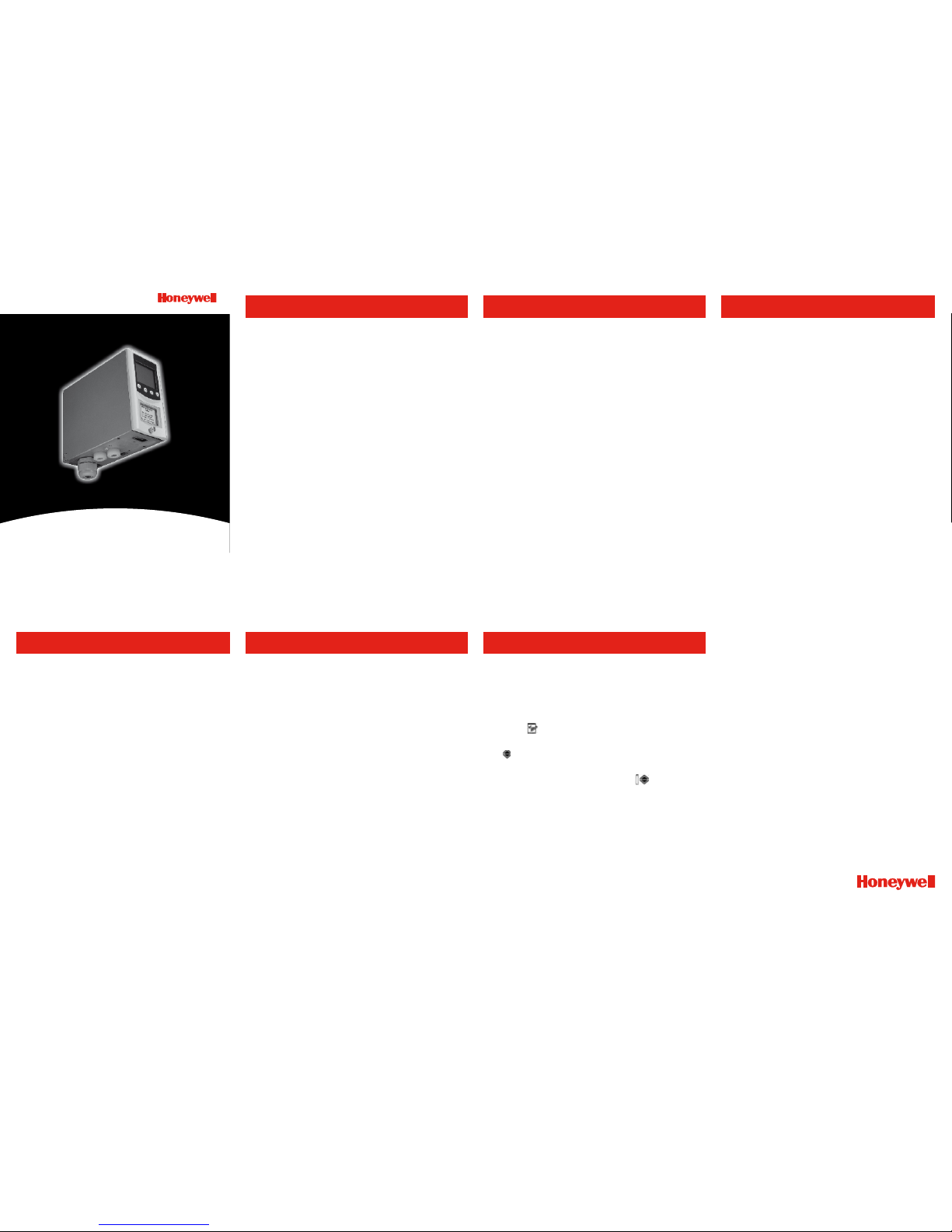
Midas® Gas Detector
High-Temperature Pyrolyzer Option
(MIDAS-T-HTP)
1. Introduction
The MIDAS-T-HTP pyrolyzer option is installed
underneath the standard Midas® gas detector. The air
sample is drawn through the pyrolyzer to the sensor
cartridge. The pyrolyzer converts peruorocompounds
(PFCs) present in the air sample into hydrogen
uoride (HF) by means of pyrolysis. The HF can then
be measured by the sensor and the concentration
displayed as the equivalent reading in ppm.
NOTE: To maintain stated sensor accuracy when
using the pyrolyzer, ensure ambient temperature of
installation point does not exceed 30°C (86°F). It is
recommended that the ventilated Midas
®
top cover
part number MIDAS-A-039 is used in all pyrolyzer
applications. Usage above this temperature may
require more frequent bump testing or calibration to
conrm working specication.
(Contact Honeywell Analytics for the availablity of
other detectable gases using this pyrolyzer module)
2. Fitting the pyrolyzer module
See reverse for all diagrams
1. Isolate power to the detector.
2. Unscrew the captive thumbscrew located on the
front panel.
3. Remove the cover by pulling it forward off the main
chassis (See Diagram 1).
4. Unscrew the two captive retaining screws located
at the bottom front of the chassis.
5. Pull the main chassis forward to disconnect it from
the mounting bracket assembly (See Diagram 2).
6. Thread the connector and wire harness from
the pyrolyzer through the rectangular access in the
bottom of the mounting bracket and secure wires
with retention clip (if available).
7. Plug the connector into the socket (con5) at the
bottom left of the terminal board.
8. Offer the pyrolyzer module up underneath the
mounting bracket ensuring that the tting at the
top rear of the pyrolyzer mates with the sample
inlet port at the bottom of the mounting bracket.
9. Align the three screw mounting bosses on the
top of the pyrolyzer with the three screw holes in
the mounting bracket.
10. Insert and tighten the three screws provided
(See Diagram 3).
3. Reassembling the Midas® detector
1. Align the PCB at the top rear of the main chassis
with the connector at the top of the mounting
bracket.
2. At the same time, align the two tubes at the
bottom rear of the main chassis with the two
tubes located on the bottom of the mounting
bracket.
3. Slide the chassis backwards on the mounting
bracket assembly so that the PCB, connector
and tubes engage fully by rmly pushing
the main chassis horizontally backwards on the
mounting bracket.
WARNING:
DO NOT PUSH ON THE LCD AS THIS MAY
CAUSE DAMAGE.
4. Align the two xing screws located at the
bottom of the chassis with the screw threads on
the mounting bracket.
5. Tighten the screws to secure the chassis to the
mounting bracket.
6. Fit the MIDAS-S-CFX sensor cartridge into the
sensor cartridge chamber (See Diagram 4, and
refer to the Sensor Cartridge Installation Quick
Start Guide MIDAS-A-021).
7. Set the power switch to the “on” position.
8. Ret optional Midas
®
ventilated top by aligning the
slots on either side with locating tabs on the
mounting bracket assembly and push the cover
horizontally until seated.
9. Tighten thumbscrew on the front panel
(See Diagram 5)
4. Conguration
1. After completion of the startup sequence, press
the ‘s’ button for a few seconds to select the
setup menu.
2. Enter the passcode (if set).
3. Use the ‘s’ or ‘t’ buttons to select the set up
menu ‘
’ icon and press the ‘3’ to accept.
4. Use the ‘s’ or ‘t’ buttons to select the set alarms
‘
ALm’ submenu and press ‘3’ to accept.
5. The ashing gas ID code is displayed along with
the gas cylinder and alarms icon ‘
’.
6. Use the ‘s’ or ‘t’ buttons to change the gas ID
number to to the appropriate PFC gas. See the
manual for further details.
7. Continue to accept or change the rest of the alarm
settings. *
8. Press ‘3’ to update all changes (UPdt displayed).
9. Press ‘X’ twice to return to normal operation.
* For further details regrading the Midas® pyrolyzer
option, refer to the Midas® operating manual
MIDAS-A-001.
Contact Honeywell Analytics:
Find out more
www.honeywellanalytics.com
Europe, Middle East, Africa, India
Life Safety Distribution AG
Wilstrasse 11-U31
CH-8610 Uster
Switzerland
Tel: +41 (0)44 943 4300
Fax: +41 (0)44 943 4398
gasdetection@honeywell.com
Americas
Honeywell Analytics Inc.
405 Barclay Blvd.
Lincolnshire, IL 60069
USA
Tel: +1 847 955 8200
Toll free: +1 800 538 0363
Fax: +1 847 955 8208
detectgas@honeywell.com
www.honeywell.com
Technical Services
ha.emea.service@honeywell.com
Asia Pacific
Honeywell Analytics Asia Pacific
#508, Kolon Science Valley (I)
187-10 Guro-Dong, Guro-Gu
Seoul, 152-050,
Korea
Tel: +82 (0)2 2025 0300
Fax: +82 (0)2 2025 0329
analytics.ap@honeywell.com
Issue 1.1 03.06
Part No. MIDAS-A-038
10/08
© 2008 Honeywell Analytics
Please Note:
While every effort has been made to ensure accuracy in this
publication, no responsibility can be accepted for errors or
omissions. Data may change, as well as legislation, and you are
strongly advised to obtain copies of the most recently issued
regulations, standards, and guidelines.This publication is not
intended to form the basis of a contract.
Page 2
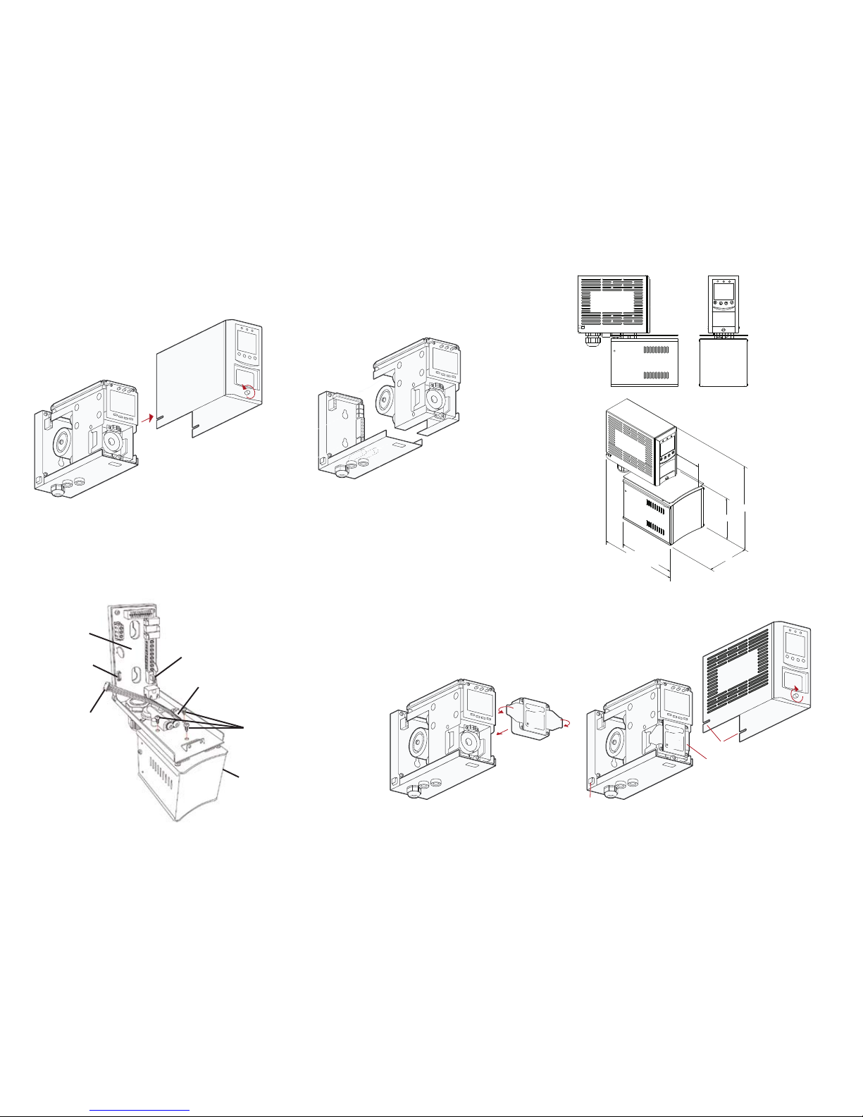
Removing the main chassis
Removing the Midas® cover
mounting
bracket
chassis
cover
loosen
Diagram 1:
Diagram 2:
mounting
bracket
?
???
?
?
?
?
????
?
???
???? ??
??
?
?
?
?
?
?
?
?
?
?
???
?
???
??
??
?
??
???
?
?
?
???
?
??
?
?
??
???
?
???
???
?
??
?
?
?
?
???
?
?
??
?
???
?
?
?
??
?
????
?
?
?
??
?
?
???
?
?
?
????
?
?
slots
tighten
tabs
cartridge fitted
?
?
???
??
??
??
?
???
?
?
?
?
?
?
?
?
?
?
?
?
???
???????
?
?
?
?
?
?
?
?
???
?
?
??
?
?
?
?
?
?
?
???
??
?
?
??
?????
?
?
???
?
?
?
?
?
??
??
?
??????
??
??
?
?
?
??
???
?
??
?
?
?
?
?????
?
??
chassis
cartridge
Diagram 4:
Diagram 5:
Fitting sensor cartridge Fitting cover
Terminal
module
Diagram 3.
Fitting the pyrolzer module
Power Switch
Rectangular access
bottom of bracket
Mounting screws (x3)
Pyrolyzer module
Socket
(con5)
Connector
4.4 in [113mm]
9.1 in [233mm]
5.5 in [140mm]
8.2 in [209mm]
2.3 in [59mm]
5.5 in [140mm]
 Loading...