

Page 1
MIDAS-M MULTIGAS TRANSMITTER
Fixed Single Point Extracted
Multi Gas Transmitter
3016M5001 Rev A
ECO HAA190080
Page 2

Page 3

Table Of Contents
Introduction
C
HAPTER 1 —
About Us
Product Description
Overview
User Interface
Default Configuration
Installation
C
HAPTER 2 —
Mount the Transmitter Device
Mount the Relay Module
Sample and Exhausting Tubing Calculations 17
7
7
7
8
9
10
11
11
15
In-Line Filters
Local Detector Option
Electrical Installation
Electrical Connection
Wiring The Relay Module
Mount The Sensor Cartridge
Device & Web Operations
C
HAPTER 3 —
Comissioning
Monitoring Mode
Review Information
18
18
19
23
26
28
29
29
30
32
Setup Operations 34
Page 4

Test Mode
36
Calibration Mode
Calibration & Bump Test 39
Bump Test 40
Internal Web Server 41
Physical Network Components 41
Internet Settings 41
Running the Web Server 42
C
HAPTER 4 —
Maintenance
System Leak Check
C
HAPTER 5 —
Additional Information
EU Directive 2012/19/EU: Waste Electrical and Electronic
Equipment (WEEE)
38
65
66
69
69
Troubleshooting and Fault Diagnosis
Specifications
Ordering
Transmitter 77
Cartridge 77
Smart Sensor 78
Accesories 78
Gas Table
Combination Index
Reflex
A Modbus/TCP Interface
70
74
77
82
84
85
86
Security 99
Page 5

Modbus TCP 99
DOS attack 99
Install Web Server Certificate in Google Chrome
Install Web Server Certificate in MS Browsers
101
103
Warranty 105
Sensor Cartridge Warranty 106
107Contact Us
Page 6

Page 7

CHAPTER
Introduction
1
Learn what you need to know about the Honeywell Midas®-M Gas Detector before operating.
About Us
Honeywell Analytics: the global leader in gas detection
While you build a better world, we’re building smarter safety.
For nearly 50 years, Honeywell Analytics has been protecting people who put their lives on the line
every day. It takes a special level of drive and dedication to work in hostile environments, and we
believe your workers deserve the same kind of commitment from us when it comes to securing
their health and safety.
Right from the start, our founders were determined to find better ways to design, build and
manufacture reliable gas detection solutions. Through advanced technology and pure industry
know-how, Honeywell Analytics continues to improve and evolve our products. Today, we’re proud
to partner with customers worldwide who share our vision of vigilance and rely on us to help them
protect what matters most.
From custom-designed solutions to unmatched training and support, Honeywell Analytics is
simply the smartest choice when you demand the best in safety.
Product Description
The Honeywell Midas®-M is a Fixed Extractive Single Point with 4-in-1 Multi Gas Detector that
draws a sample locally or from a remote point to a sensor cartridge that is located inside the
detector’s chassis. A wide range of toxic, flammable and oxygen gas sensor cartridges are
available that enable detection of gases used or generated in the Semiconductor and other
manufacturing industries.
Midas-M is shipped from the factory with the security function disabled. We strongly recommend
enabling this function for safe use of the detector. To enable it, select Set up > Security and type an
8 character password.
Midas-M is wall mounted and displays gas concentration, alarm, fault and status information via
its backlit LCD and LEDs. A simple to use 4-button keypad located under the display provides the
facility to set-up, review, operate and make changes to the detector’s configuration.
Midas-M 7 User Manual
Page 8
Midas-M has flexible power and communications capabilities built in as standard. These include
3 on board relays, 0-21 mA analog output, Modbus/TCP outputs for signal and service
connectivity as well as Power over Ethernet (PoE) connection that enables a single Ethernet
connection to be made for all power, control and communication requirements.
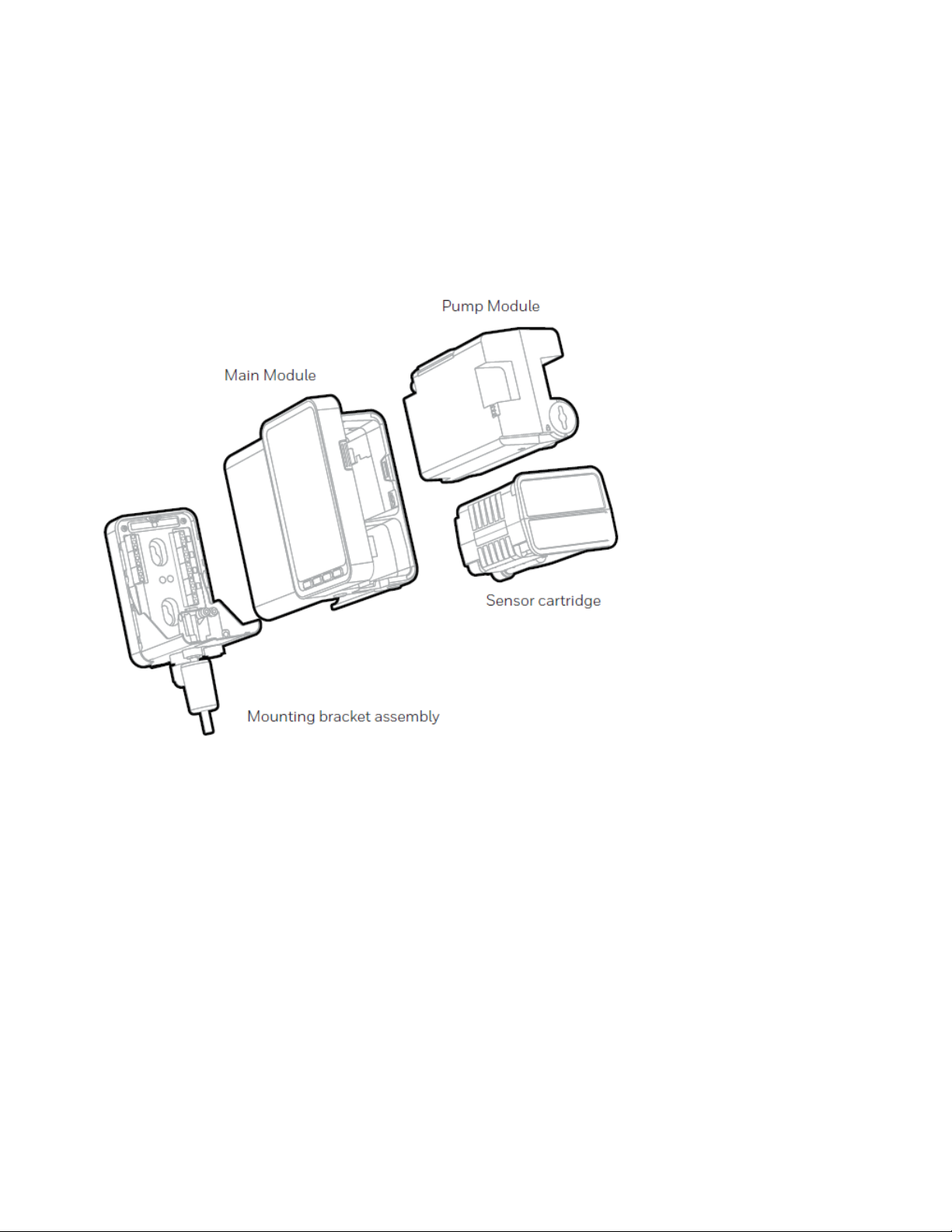
Overview
The Midas-M gas detector comprises of 4 parts: the main module, the mounting bracket
assembly, the sensor cartridge and the pump module.
Midas-M 8 User Manual
Page 9
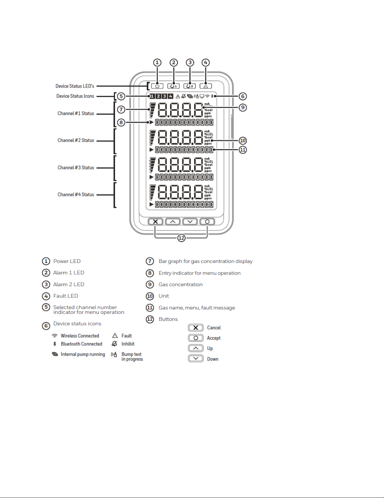
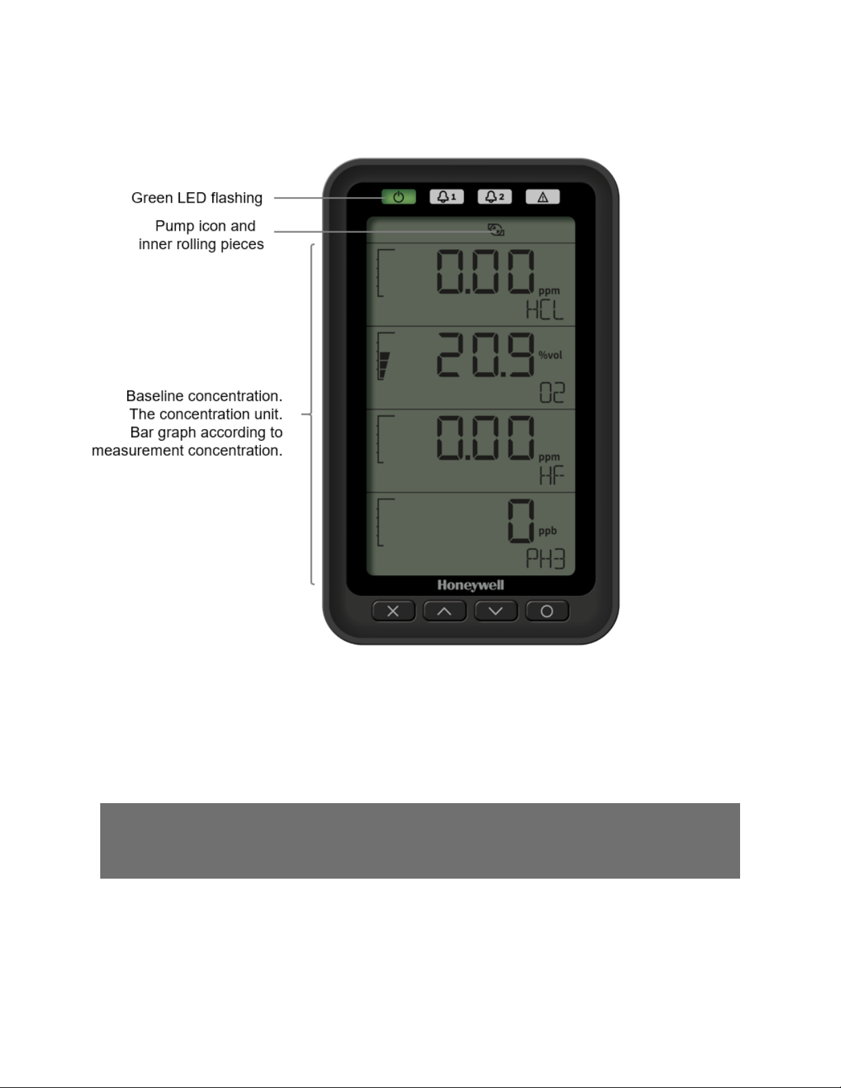
User Interface
Detector's User Interface overview.
Midas-M 9 User Manual
Page 10

Default Configuration
The Midas-M gas detector is factory-configured.
NOTE: Oxygen levels are 20.9% v/v in a normal atmosphere, equivalent to 17.3 mA. Use caution
when integrating an oxygen Midas-M unit using the 4-20 mA output since fault, inhibit, and no
power conditions are below 4 mA and, by default, an oxygen depletion alarm is triggered on a
falling alarm (default 19.5% v/v). In that case, Honeywell Analytics recommends one of the
following:
• Use Modbus TCP digital communications
• Use discrete relay inputs instead of a 4-20 mA signal to trigger gas alarms
• Program the control system of the 4-20 mA input with logic and a delay (e.g., 1 second) before
triggering an alarm to determine if the 4-20 mA output is at one of the 0-4 mA conditions
described above.
Contact Honeywell Analytics for further information.
Factory Default Configuration
Toxic Gas flammable gas
1
oxygen
Full Scale (FS) Typically4 x Threshold
LimitValue (TLV)
Alarm 1
(Relay 1)
Alarm 2
(Relay 2)
Fault
(Relay 3)
Latching Latching. Alarm and fault relays DO NOT automatically reset when reading
Passcode No Passcode set.
Address 169.254.60.47 subnet mask 255.255.255.0
Current source with:
1.0 mA Fault
2.0 mA Inhibit
3.0 mA Maintenance Fault
4.0 to 20.0 mA Gas reading (normal operation)
21.0 mA Over range
1/2 TLV 10% LEL 23.5% v/v (Rising)
Normally de-energized, energizeson alarm.
TLV 20% LEL 19.5% v/v (F alling)
Normally de-energized, energizeson alarm.
Normally energizes, de-energizedon fault.
fallsbelow alarm thresholds.Relays MUST be manually reset.
100% Lower Explosive
Limit(LEL)
25% V olume (v/v)
1
Not yet released
Midas-M 10 User Manual
Page 11
CHAPTER
2
For ease of installation Midas-M has been designed to allow the installation of the mounting
bracket assembly and main module separately from the other parts of the detector. The detector
location and hard wiring can therefore be completed before fitting the detector’s main module
and sensor cartridge.
WARNING
Midas-M is designed for installation and use in indoor safe area non-explosive
atmospheres. Installation must be in accordance with the recognized standards of the
appropriate authority in the country concerned. Prior to carrying out any installation
ensure local regulations and site procedures are followed.
Ensure the connection of all modules (e,g pump, and cartridge module) with the main
module. Otherwise, Midas-M can have flow leakage or malfunction.
Installation
Mount the Transmitter Device
The Midas-M gas detector has an integral mounting bracket assembly that is easily mounted to a
suitable vertical surface such as a wall, tool housing, mounting plate on a pole etc.
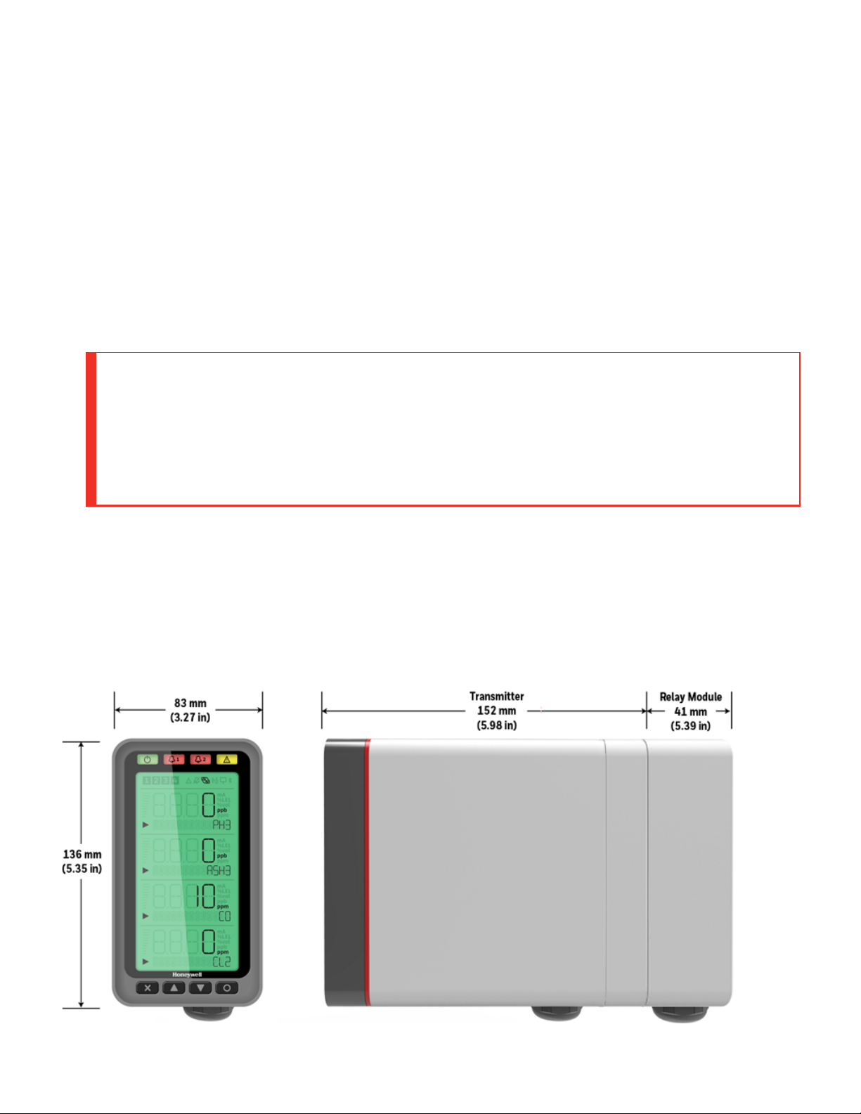
Midas-M outline dimensions
Midas-M 11 User Manual
Page 12
NOTE
Notice the space required to install the instrument, open the door, push in/pull out
modules, and tubing.
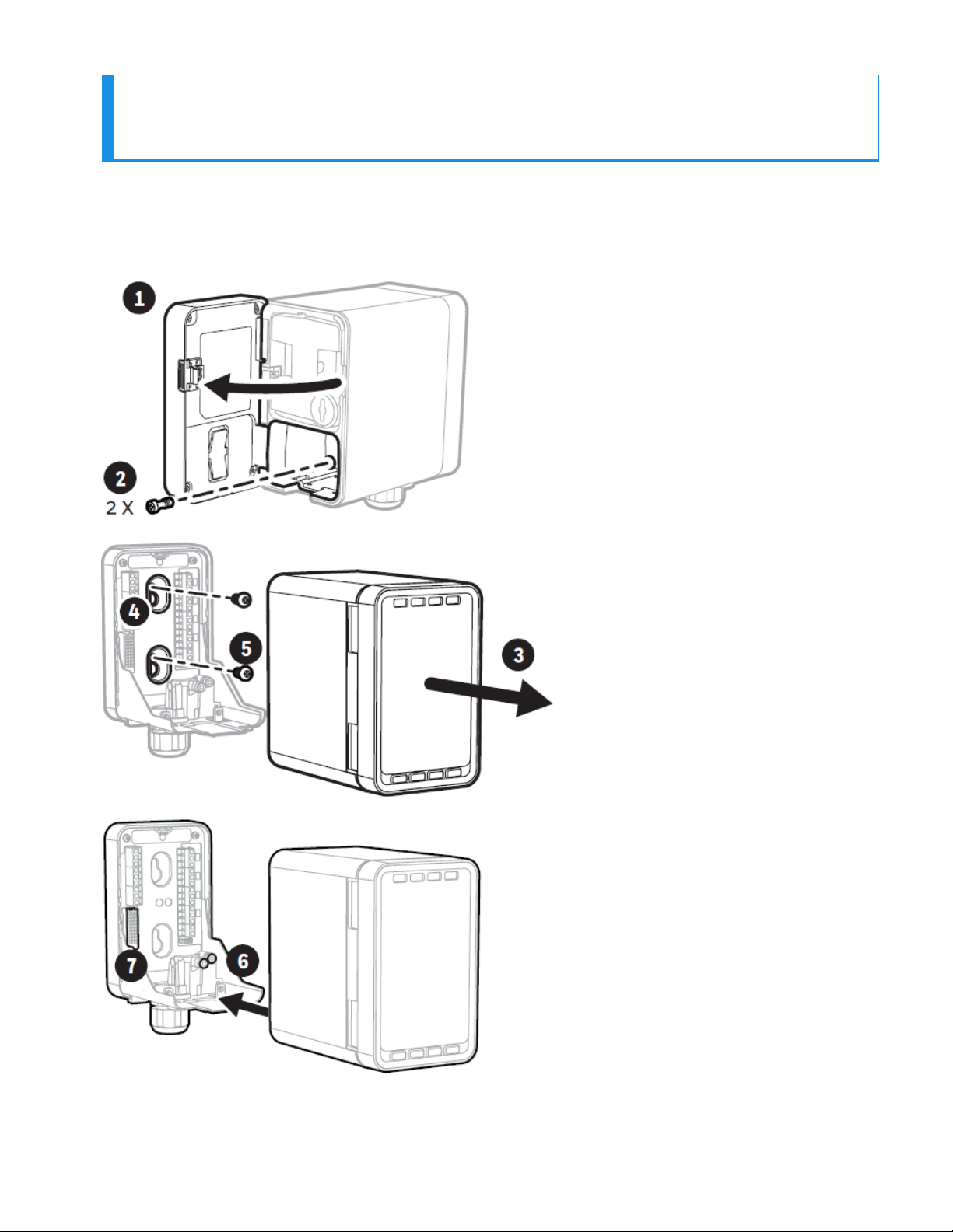
Mounting procedure
Midas-M 12 User Manual
Page 13
1. the door.
2. Un-tight the two screws.
3. Carefully pull the main module forward.
4. Drill two holes 2.2 in (55.9 mm) Use 2 x M4 Screws or equivalent for mounting
(head size 7-11 mm).
Midas-M 13 User Manual
Page 14
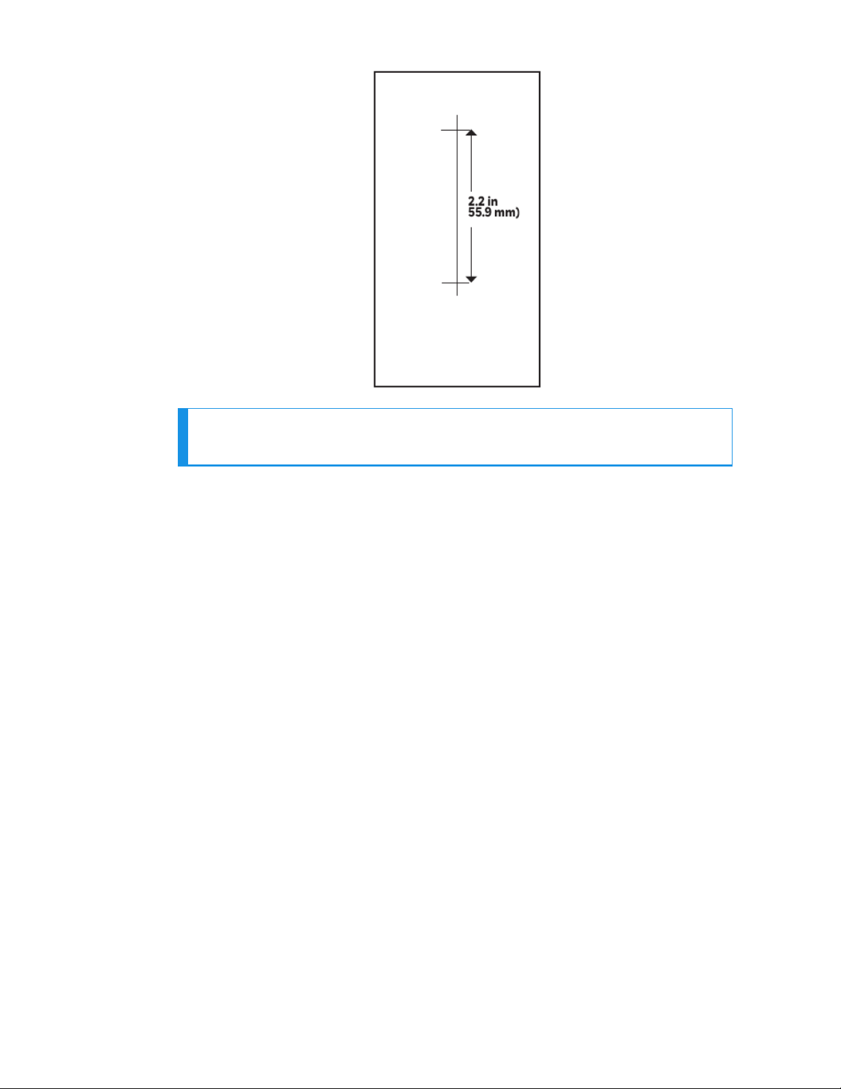
NOTE
This drill template is not to scale.
5. a. Partially screw the fixings into the mounting surface.
b. Place the mounting bracket assembly over the screws, so they pass
through the mounting holes and then slide down to locate in the slots.
c. Tighten the screws to secure the mounting bracket assembly.
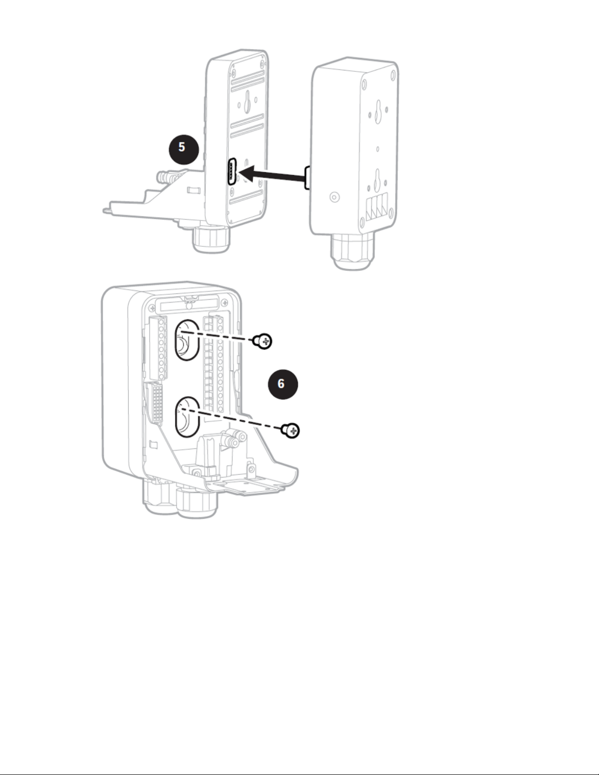
6. a. Align the rounded corner at the lower of the main module with the similar
rounded corner at the bottom of the mounting bracket assembly
b. Slide the main module backward while pushing the main module up after
connecting with a mounting bracket so that the PCB connector and tubes
engage simultaneously.
7. Ensure the PCB, connector, and tubes are fully engaged by firmly pushing the
main module horizontally backward on the mounting bracket assembly. DO
NOT PUSH ON THE LCD AS THIS MAY DAMAGE IT.
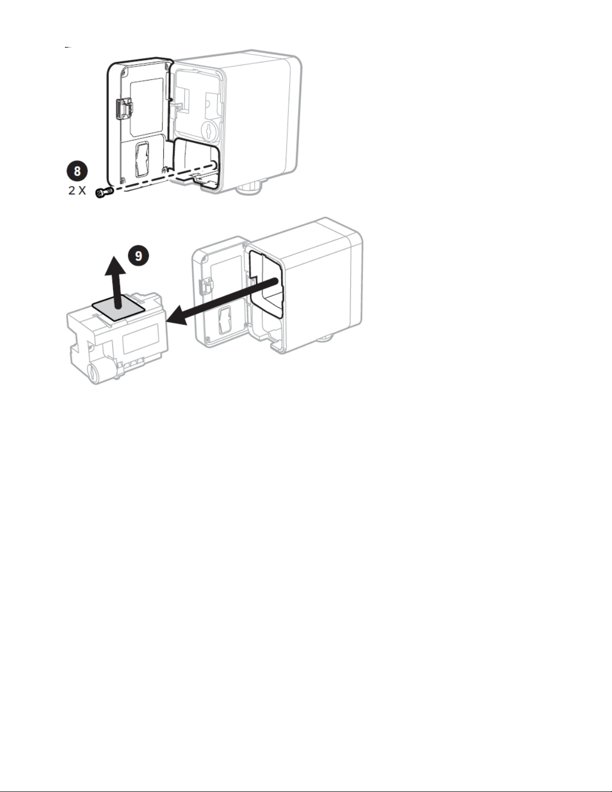
8. a. Align the two fixing screws located at the bottom of the module with the
screw threads on the mounting bracket assembly.
b. Tighten the screws to secure the module to the mounting bracket
assembly.
9. Remove the internal packing card securing the pump. Failure to remove this
packing will result in damage to the Midas-M detector.
Midas-M 14 User Manual
Page 15
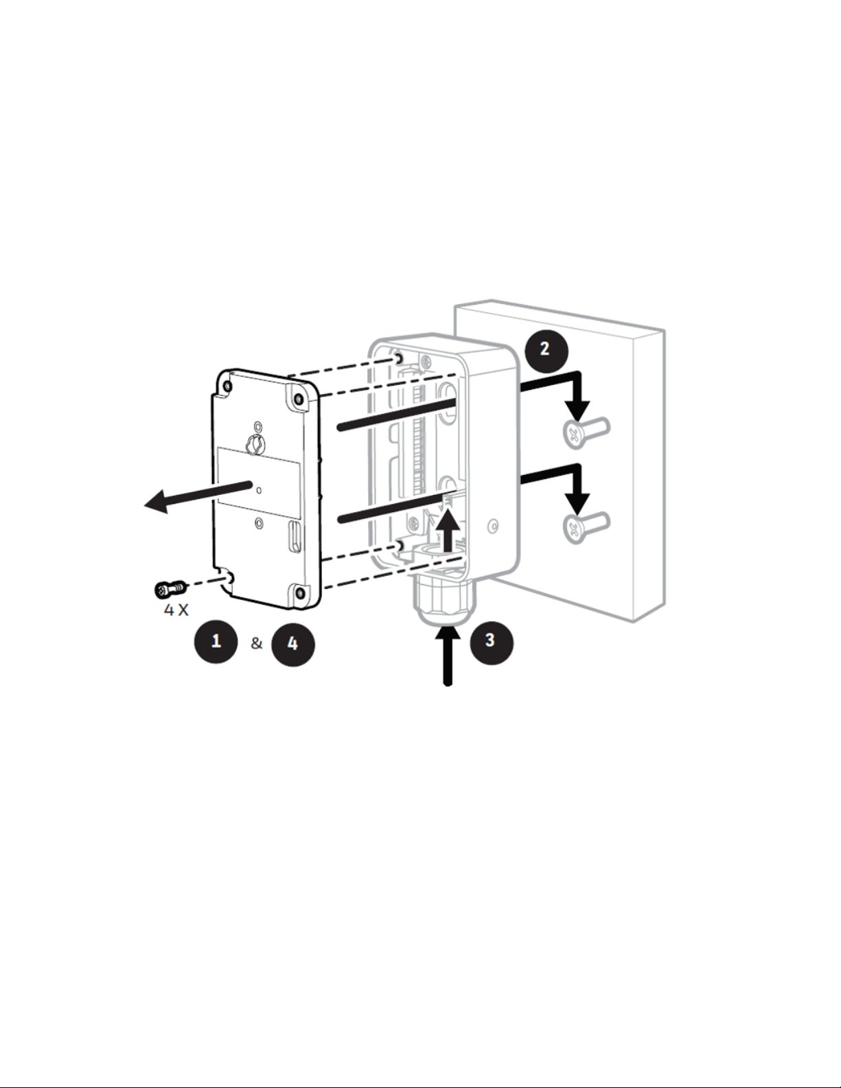
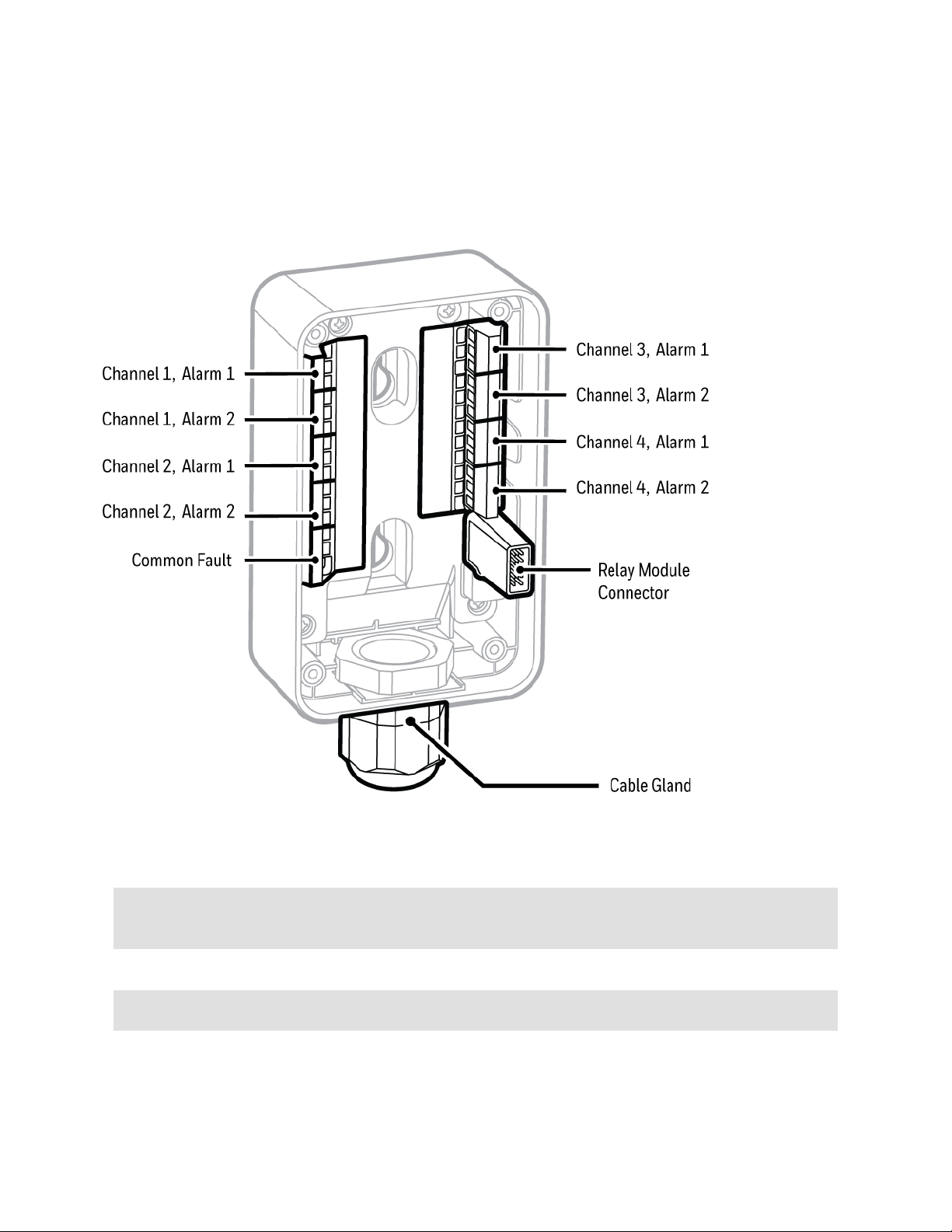
Mount the Relay Module
The Relay Module has an integral mounting bracket assembly that is easily mounted to a
suitable vertical surface such as a wall, tool housing, mounting plate on a pole etc.
1. Pull out the four screws and remove the plate cover.
2. a. Partially screw the fixings into the mounting surface.
b. Place the Relay module over the screws, so they pass through the holes to locate in
the slots.
c. Tighten the screws to fix the Relay Module to the surface.
3. Connect the wire through the cable gland to the terminal block.
4. Place the plate cover in position and screw the four screws you removed in Step 1.
5. Push the mounting bracket assembly horizontally and engage the Relay Module connector.
6. a. Align the screw holes and the slot-boundaries, and tight the machine screws
(3016D0355) provided in packaging.
b. Connect the mounting bracket assembly to the Relay Module.
Midas-M 15 User Manual
Page 16
Midas-M 16 User Manual
Page 17

Sample and Exhausting Tubing Calculations
Description of flow rate, and tubing vacuum at the inlet and exhaust points,
Inlet sample specifications
Description Maximum
Tubing Length, m (ft) 30 (100)
Sample Point Vacuum -25.4 cm H2O (-10 in H2O)
Transport Time (sec), ID 1/8”
Transport Time (sec), ID 3/16” 53
Flow rate, cc/min. 600 (Flow is constant)
Tubing OD, mm (in) 6.35 (0.25)
Tubing ID, mm (in) 3.18 (0.125)
1
Honeywell Analytics recommends thick-wall tubing (1/8” ID) for best speed of response. Due to
its lower surface area, thick- wall tubing may require less conditioning than thin-wall tubing.
2
The flow rate is electronically maintained at approximately 600 cc/min and may vary within
acceptable tolerances.
Tubing lengths vary among gases. See the Gas Chart for recommended lengths.
NOTE
Honeywell Analytics recommends the use of Teflon FEP (Fluorinated Ethylene Polymer)
tubing to assure proper sample transport. The properties of Teflon FEP make it the best
choice for transporting sample toxic gases to instruments when compared with the
properties of other similar tubing materials.
1
25
2
Outlet sample specifications
description maximum
Tubing Length, m (ft) 30 (100)
Back Pressure at Exhaust Point 20.3 cm H2O (8 in H2O)
Flow rate, cc/min 600 (Flow is constant)
Midas-M 17 User Manual
Page 18

description maximum
Tubing OD, mm (in) 6.35 (0.25)
Tubing ID, mm (in) 4.76 (0.188)
Prepare Tubing
1. Cut the tube squarely and remove any burrs.
2. Mark from end of tube the length of insertion. The insertion lenght of Midas-Mfrom the end
of tube is 15.5 mm.
NOTE
When inserting the tube into the inlet/outlet port of the Midas-M, make sure that it is
inserted up to the marked position.
In-Line Filters
External filters must be used to protect the tubing from contamination. Use particulate filter part
number 780248 for normal gases and 1830-0055 or 1991-0147 for corrosive gases. Replace
the filter every 3 months. Refer to the Gases Table for specific gases.
Local Detector Option
The Midas-M gas detector can also be used to monitor for gas at the location of the detector. To
do this, an inline filter is simply connected to the sensor cartridge gas inlet port. The external
dust filter part number is 780248 for normal gases and 1830-0055 or 1991-0147 for corrosive
gases. The area around the detector is then being monitored as opposed to a sample being
drawn from a remote location.
Midas-M 18 User Manual
Page 19
Electrical Installation
Access for the electrical wires to the terminal module is made via the PG16 cable gland located
at the bottom of the mounting bracket assembly. The cable gland can be removed and replaced
with a suitable conduit fitting if required.
Typical wire routing
The terminals used are suitable for conductors of 24 to 14 AWG (0.5 to 1.8mm Dia.). We
recommend using the 16 AWG (1.5 mm Dia.) conductors.
If Power over Ethernet (PoE) is used to power the device, then 24 VDC power must not also be
connected to the device, (or conversely, if 24 VDC is used to power the Midas-M, then electrical
power via the Ethernet port must not be applied). Failure to observe this requirement may cause
damage to the gas detection system and will not be covered by the standard warranty.
When connecting the wires ensure that the power switch is in the off position.
NOTE
Earthing Requirements: If the Midas-M unit’s metal chassis is not connected directly to a
metal surface for earthing purposes, an additional earth wire will be required. Connect a
Midas-M 19 User Manual
Page 20
wire via the PG16 gland to the dedicated earth tag (screw terminal) located on the bottom
bracket and connect the other end of the wire to a dedicated external earthing point. If
Power over Ethernet (PoE) power supply is being used, shielded CAT5 Ethernet cable is
recommended. Please ensure that your wiring avoids earth ground loops that may affect
the performance of your equipment.
NOTE
Instrument grounding is required to ensure stable performance and to limit the effects of
radiofrequency interference before installation.
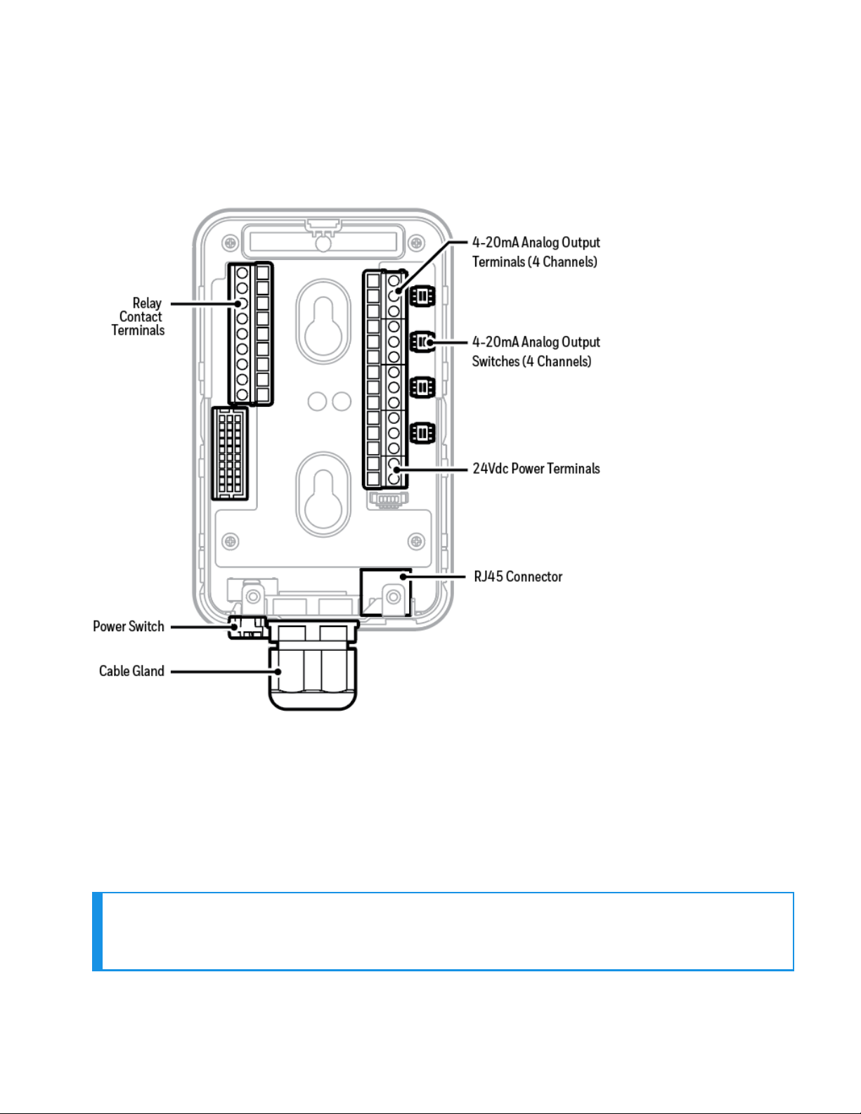
The following diagram shows the terminal module layout and terminal identification as well as
the jumper locations.
Transmitter Terminals
Midas-M 20 User Manual
Page 21

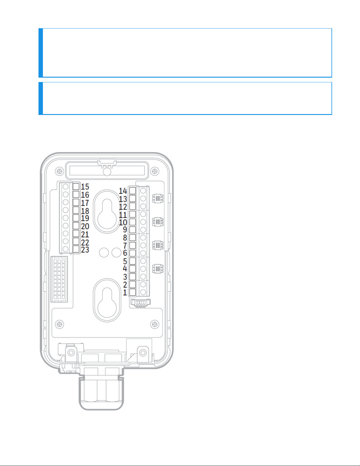
Transmiter Terminals
terminal number function description
1 24Vdc Input 0Vdc
2 24Vdc Input +24Vdc
3 mA output - Channel 1 COM
4 mA output - Channel 1 mA-
5 mA output - Channel 1 mA+
6 mA output - Channel 2 COM
7 mA output - Channel 2 mA-
8 mA output - Channel 2 mA+
9 mA output - Channel 3 COM
10 mA output - Channel 3 mA-
11 mA output - Channel 3 mA+
12 mA output - Channel 4 COM
13 mA output - Channel 4 mA-
14 mA output - Channel 4 mA+
15 Relay 1 Normally Closed
16 Relay 1 Common
17 Relay 1 Normally Open
18 Relay 2 Normally Closed
19 Relay 2 Common
20 Relay 2 Normally Open
21 Relay 3 Normally Closed
Midas-M 21 User Manual
Page 22
terminal number function description
22 Relay 3 Common
23 Relay 3 Normally Open
Relay function table
Display Description Relay 1 Relay 2 Relay 3
INSTRUMENT F
ONLY
SEPARATE F
COMBINED F
Midas-M 22 User Manual
Instrument fault
only
Separate fault
relays
Combined fault
relay
Alarm 1 Alarm 2
Any
alarm
Alarm 1 Alarm 2 Any fault
Maintenance
fault
Instrument
fault
Instrument
fault
Page 23
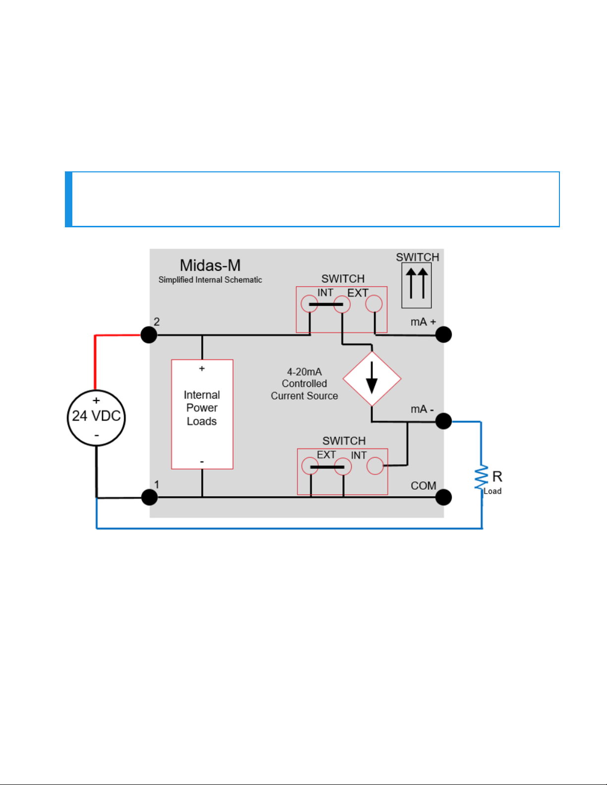
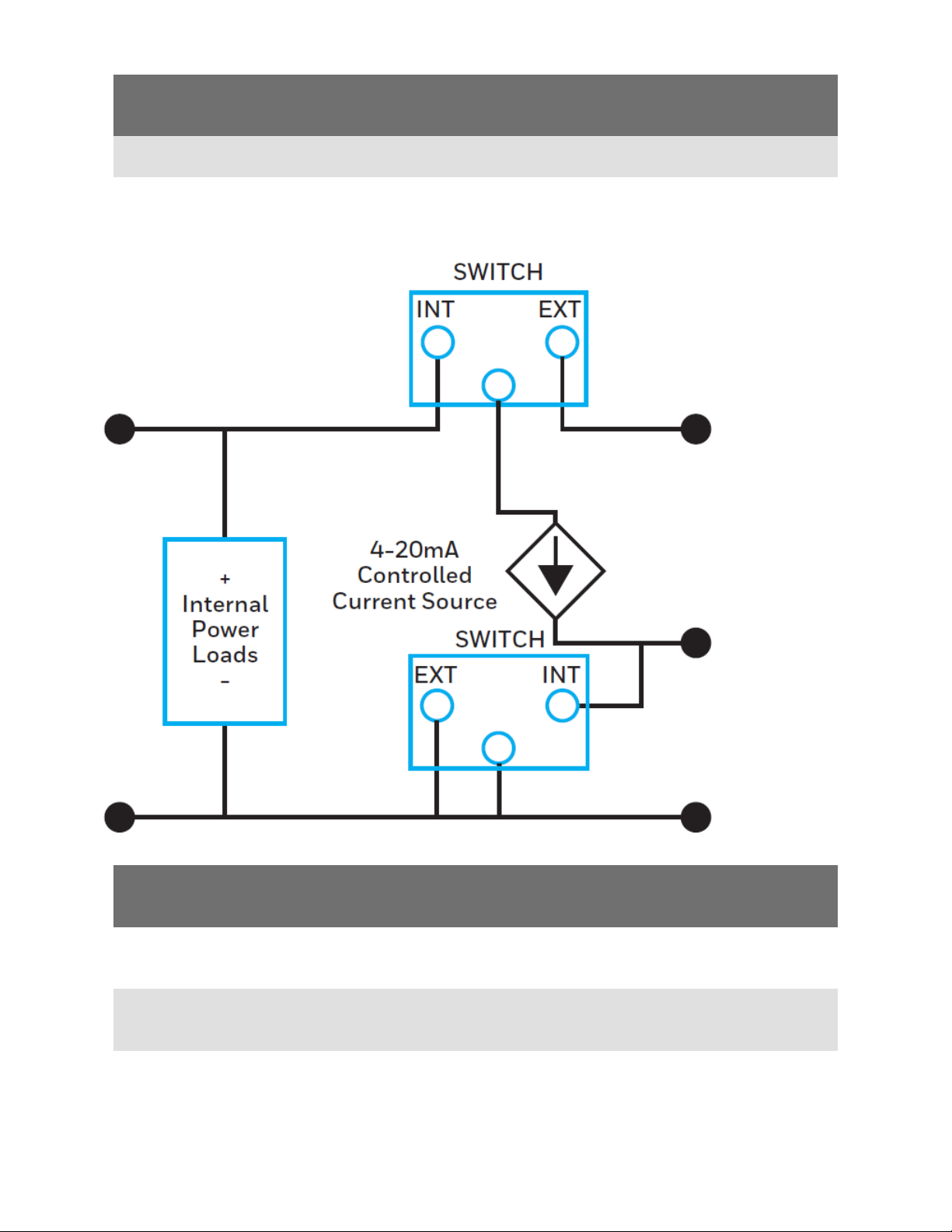
Electrical Connection
Midas-M can be powered by either 24 VDC via traditional discrete wiring or by approximately 48
VDC delivered through the Ethernet cable from a PoE source. In either case, the 4-20 mA analog
output can be used.
The analog output can be configured for fully isolated operation. With 24 VDC power the 4-20
mA output can be configured for sink, source or isolated output operations. Following are some
schematic diagrams of typical electrical connection configuration.
NOTE
When wiring the Midas-M Transmitter to a controller, program the controller for a 1-2
second delay before reporting to prevent false alarms.
Generic example Midas-M 3-wire sourcing
Midas-M 23 User Manual
Page 24
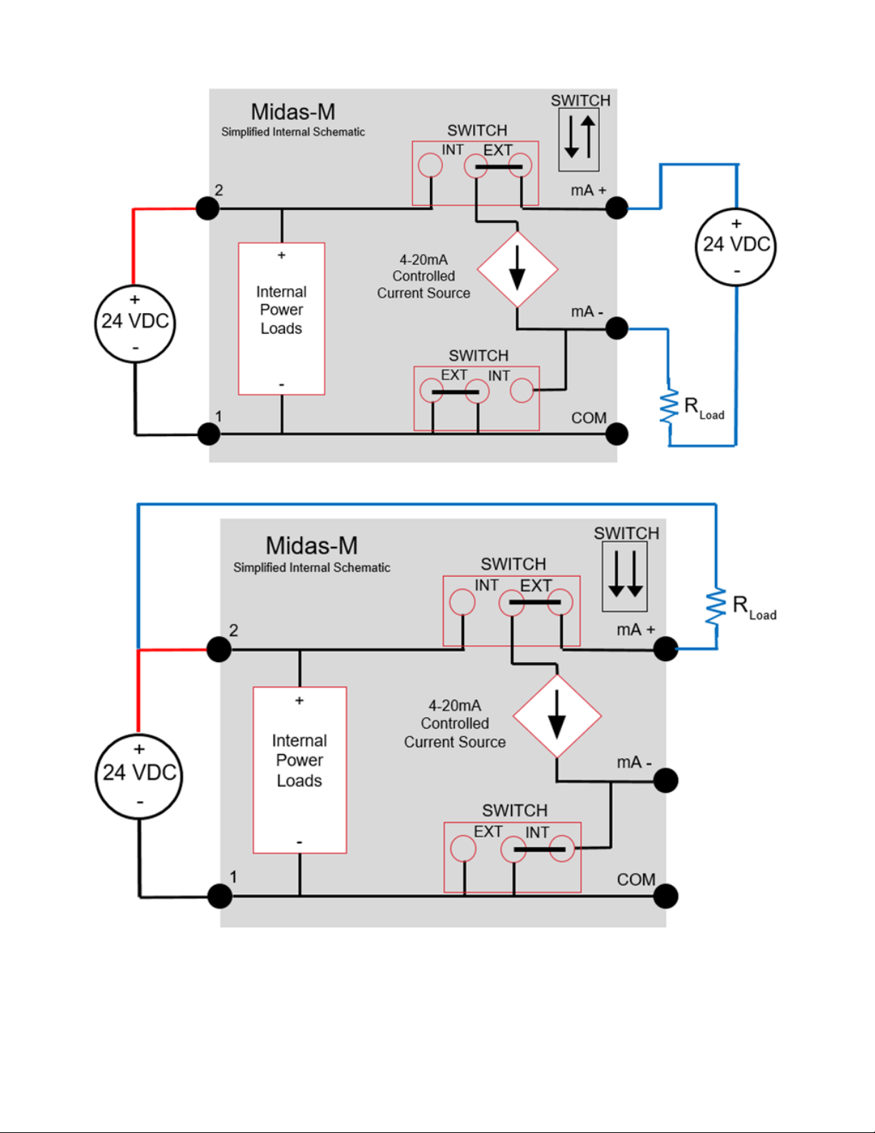
Generic example Midas-M 4-Wire Isolated output
Generic example Midas-M 3-wire Sinking output
Midas-M 24 User Manual
Page 25
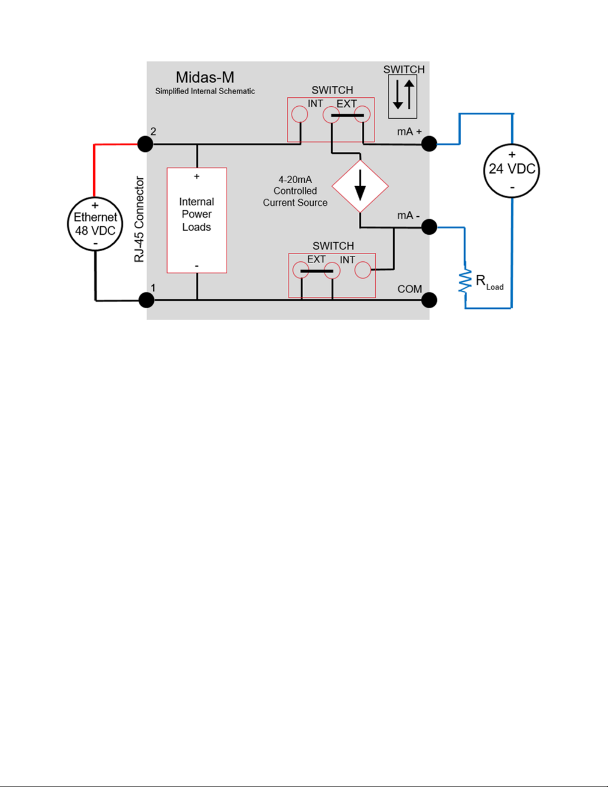
Generic example Midas-M Isolated 4-20mA output w/PoE power
Midas-M 25 User Manual
Page 26
Wiring The Relay Module
The Midas-M relay module contains:
Nine relays to activate external devices.
Eight gas alarm relays which indicate level 1 and level 2 alarms of each channel.
A common fault relay which indicate maintenance fault or instrument fault.
Specifications
Power Supply
Power
consumption
Relay rating 1.0 A @ 30VDC or 0.5 A @ 125 VAC max, 10 uA @ 10 mV minimum
Wiring 14 AWG maximum per each channel
Midas-M 26 User Manual
No separated power supply required Supplied from the Midas-M
transmitter
< 1.45 W
Page 27

Default configuration
All alarm relays Normally de-energized, energized on alarm
Common fault relay Normally energized, de-energized on fault
Midas-M 27 User Manual
Page 28
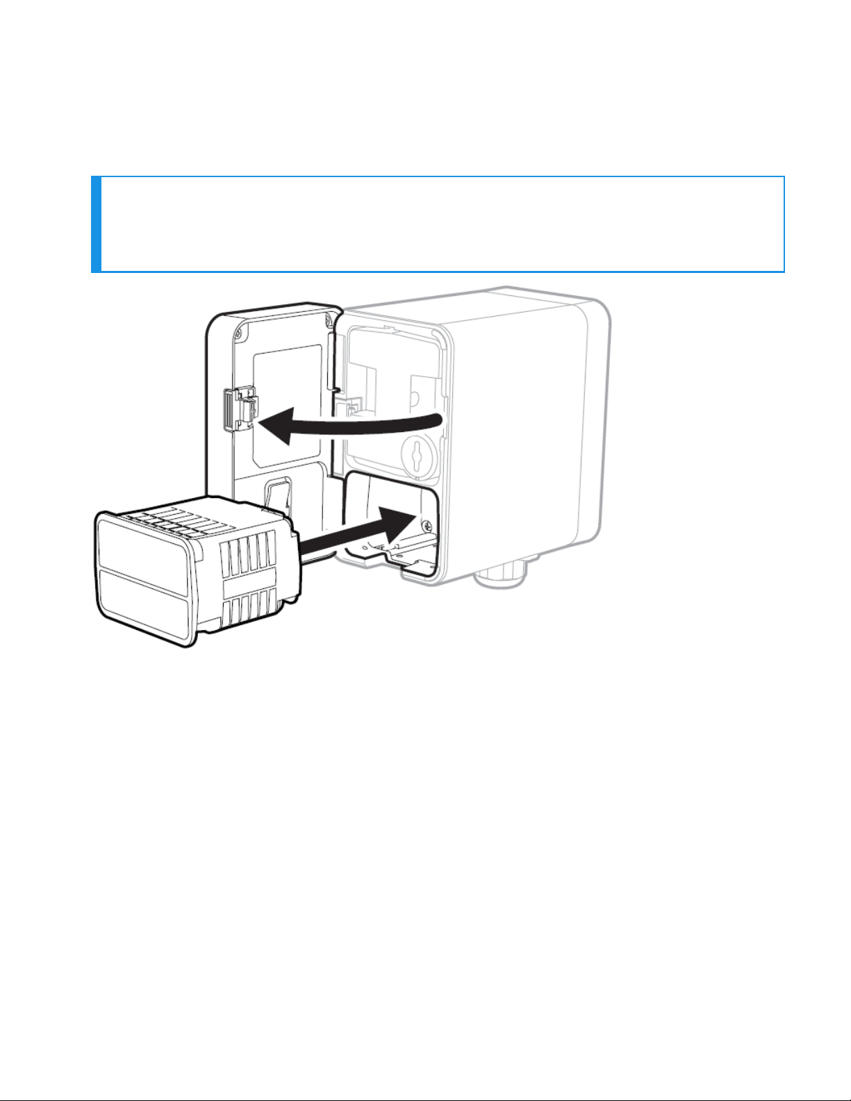
Mount The Sensor Cartridge
The Midas-M Sensor Cartridge enables the detection of a wide range of asphyxiant, toxic,
flammable, pyrophoric, corrosive, and oxidizer (including Oxygen) gases. The plug & play Sensor
Cartridge is located inside the detector’s chassis.
NOTE
The Midas-M sensor cartridge is supplied separately.
Before use, verify the part number and type of sensor cartridge is correct for your
application.
1. Turn the power off.
2. Open the door and remove the BiAS battery module and the two plug caps from the sensor
cartridge.
3. Align the Sensor cartridge pins with the socket in the sensor cartridge chamber and then
push the sensor cartridge gently until fully seated.
4. Close the door.
5. a. Press the ‘O’ button to clear the “Detect New Cartridge ” message.
b. Confirm that the green LED is flashing, and that the yellow and red LEDs are off.
c. Confirm the display shows a concentration of zero as appropriate.
Midas-M 28 User Manual
Page 29

CHAPTER
3
Learn what you can do with your Honeywell Midas®-M Detector, from commissioning to
Maintenance
Device & Web Operations
Comissioning
Comissioning should be followed carefully and only performed by suitably trained personnel.
WARNING
Before carrying out any work, ensure local and site procedures are followed. Ensure that
the associated control panel is inhibited to prevent false alarms.
1. Ensure the detector is wired correctly.
2. Ensure that the correct sensor cartridge is fitted. (If the cartridge has not been stored at room
temperature, allow one hour for equilibration.)
3. Ensure the ON/OFF switch on the bottom of the mounting bracket assembly is in the ON
position.
4. Apply power to the system. Wait for a couple of minutes until the start-up routine completes.
5. After the start-up routine, the detector will display the Normal/Monitoring Operating Mode.
6. Perform a leak test to ensure all connections are secure. ‘Waiting…’ will be displayed on booting
time.
7. Allow the detector to stabilize until the ‘Warm-up’ message is no longer displayed after booting.
The maximum warm-up time is dependent on sensor type. Refer to individual cartridge data
sheets. Warm-up times are typically much faster.
8. Ensure the correct ID code is selected in Set-up > alarm menu
9. If this is a first-time start-up, the “Detect New Cartridge ~” message could be displayed. Press
the ‘O’ button to clear the message.
Midas-M 29 User Manual
Page 30
Monitoring Mode
After commissioning, the Midas-M detector is set in the Monitoring Mode, which is the starting
point for all of the device's operations.
The examples in the following table are for a linear 4-20 mA output over a full scale range of 2
ppm. The current output for a given gas concentration will be different for other full scale
ranges (linear 4 mA = 0 % full scale to 20 mA = 100 % full scale). The alarm and fault relays are
in default (latching) mode.
Normal Operation Display and Outputs.
This table is based on the default configuration of toxic sensor type.
Status Relay Status
Alarm 1
Midas-M 30 User Manual
Alarm relay 1
activated
4-20mA output
mA output to
match the
concentration
LEDs Backlight
Green flash
Alarm 1 Red
on
Red on of the
channel
Page 31

Status Relay Status
Alarm relay 2 deactivated
Fault relay deactivated
4-20mA output
LEDs Backlight
Alarm 2
Greater than
full scale
Inhibit
Alarm relay 1 activated
Alarm relay 2
activated Fault relay
de-activated
Alarm relay 1
activated
Alarm relay 2
activated
Fault relay deactivated
Alarm relay 1 deactivated
Alarm relay 2 deactivated
Fault relay deactivated
mA output to
match the
concentration
21mA
2mA Green flash
Green flash
Alarm 1 Red
onAlarm 2
Red flash
Green
flash
Alarm 1
Red on
Alarm 2
Red flash
Yellow on
Red flash of the
channel
Yellow on of the
channel
Alarm relay 1 deactivated
Green
Maintenance
fault
Instrument
fault
Midas-M 31 User Manual
Alarm relay 2 deactivated
Fault relay deactivated
Alarm relay 1 deactivated
Alarm relay 2 deactivated
Fault relay
activated
3mA
1mA
flash
Yellow on
Green
flash
Yellow
flash
Yellow on of the
channel or all
channels dependent
on fault type
Yellow flash of the
channel or all
channels dependent
on fault type
Page 32

Review Information
From the Review Mode, you can see the information of transmitter, cartridge, alarm, 4-20mA,
relays, fault, calibration, date/time, network, event log, and advance.
1. Go to the Monitoring Mode.
2.
By pressing or buttons you are entered automatically to the Review Mode and one
of the Review options is displayed under Review.
3.
Press or buttons to scroll to your desired option.
4.
Press to accept and enter the selected option.
5. Repeat Steps 3 and 4 to continue exploring more options from the Review Mode.
6.
Optional Step: Press to cancel and return one step back.
From the Review Mode panel, you can review any of the following options:
Option Information you can review from selected option
l FW Revision
l Part Number
Transmitter
Cartridge
l Serial Number
l FW checksum
l Web version
l FW Revision
l Boot loader revision
l Part Number
l Serial Number
l Sensor parameter revision of each channel
Alarms
l Gas type of each channel
Midas-M 32 User Manual
Page 33

Option Information you can review from selected option
l Alarm 1 type and level of each channel
l Alarm 2 type and level of each channel
l Deadband level of each channel
l Alarm latching/non-latching of each channel
l Alarm delay time of each channel
4-20mA Concentration range of 4-20mA output of each channel
Internal Relays
l Relay configuration
l Relay energized/de-energized in normal condition
External Relays Relay energized/de-energized in normal condition
l Latching/Non-latching
Faults
Calibration
l Maintenance fault enable/disable
l Temperature fault enable/disable
l Calibration interval of each channel
l Calibration due days of each channel
l Sensor expired days of each channel
Date/Time Date and Time
l IP obtain method
l IP address
Network
l Subnet Mask
l Gateway
l MAC Address
Event Log Event logs
Advance Channel ON/OFF
Midas-M 33 User Manual
Page 34

Setup Operations
From the Setup Mode, you can configure alarms, 4-20mA, relays, faults, channels, date & time,
network, advance, and security.
1. Go to the Monitoring Mode.
2.
Press or buttons and hold for one second to enter the Main Menu, and one of the
Menu options is displayed.
3.
Press or buttons to scroll to Setup.
4.
Press to accept and enter the Setup menu.
5.
Press or to continue exploring more options from the Setup Mode, and then press
to accep it.
6.
Optional Step: Press to cancel and return one step back.
From the Setup Mode panel, you can review any of the following options:
Option Operations you can Setup from selected option
l Gas type of each channel
l Correlation factor of each channel if gas type is “USER”
l Alarm 1 type and level of each channel
Alarms
4-20mA Concentration range of 4-20mA output of each channel.
l Alarm 2 type and level of each channel
l Deadband level of each channel
l Alarm latching/non-latching of each channel
l Alarm delay time of each channel
Internal
l
Relay configuration (Instrument Fault Only, Separate Fault Relay,
Midas-M 34 User Manual
Page 35

Option Operations you can Setup from selected option
Combined Fault Relay).
Relays
l
Relay energized/de-energized in normal condition.
External
Relays
Faults
Relay energized/de-energized in normal condition.
Latching/Non-latching Maintenance fault enable/disable Temperature fault
enable/disable.
Calibration Calibration interval of each channel
l Date
Date/Time
Network
l Date format (YYYY MM DD, DD MM YYYY, MM DD YYYY)
l Time
l IP obtain method (Manual, Auto)
l IP address
l Subnet Mask
l Gateway
Advance Channel ON/OFF
Security
l Security ON/OFF
l Password
Midas-M 35 User Manual
Page 36

Test Mode
From the TestMode, you can test Bump, Simulation, 4-20mA, and Inhibit.
1. Go to the Monitoring Mode.
2.
Press or buttons and hold for one second to enter the Main Menu, and one of the
Menu options is displayed.
3.
Press or buttons to scroll to Test.
4.
Press to accept and enter the Test menu.
5.
Press or to continue exploring more options from the Test Mode, and then press
to accep it.
6.
Optional Step: Press to cancel and return one step back.
From the Test Mode panel, you can test any of the following options:
Option Operations you can Test from the selected option
Bump Gas bump test
l Alarm 1 of each channel
Simulation
4-20mA Force 4-20mA output of each channel
Inhibit
l Alarm 2 of each channel
l Maintenance Fault
l Instrument Fault
l Inhibit ON/OFF
Midas-M 36 User Manual
Page 37

Option Operations you can Test from the selected option
l Inhibit time
Midas-M 37 User Manual
Page 38

Calibration Mode
From the Configuration Mode, you can configure Zero, Span, Flow, and 4-20mA.
1. Go to the Monitoring Mode.
2.
Press or buttons and hold for one second to enter the Main Menu, and one of the
Menu options is displayed.
3.
Press or buttons to scroll to Calibration.
4.
Press to accept and enter the Calibration menu.
5.
Press or to continue exploring more options from the Calibration Mode, and then
press to accept it.
6.
Optional Step: Press to cancel and return one step back.
From the Calibration Mode panel, you can configure any of the following options:
Option Operations you can calibrate from the selected option
Zero Zero gas calibration of each channel
Span Span gas calibration of each channel
Flow Pump flow calibration
4-20mA 4-20mA output calibration of each channel
Midas-M 38 User Manual
Page 39

Calibration & Bump Test
All Midas-M sensor cartridges are pre-calibrated by Honeywell Analytics using traceable gas
standards and approved calibration methods to a proven ISO 9000 quality controlled procedure.
The Midas-M sensor cartridge design is very robust and resistant to long term drift; in fact in a
normal operating environment it is possible to extend the calibration interval with Midas-M up
to 24 months (subject to local requirements concerning calibrations). This design feature is
another element that supports Midas-M as a long term cost effective gas detection solution.
Honeywell Analytics recommends frequent bump testing to confirm performance.
NOTE
It is the sole responsibility of each user to determine their own calibration and bump test
schedule based on their own safety assessments and understanding of local requirements.
Just prior to commissioning, each Midas-M unit should be zero calibrated to ensure accuracy. It
is recommended that the unit be powered with the cartridge installed for at least 30 minutes
prior to conducting a zero calibration. A second zero calibration may be required after a 24 hour
period which is dependent on the site conditions. O2 sensors are not zero calibrated but should
be span gas calibrated. See the Gas Table for span gas calibration details. If the ambient
condition in the area the detector is monitoring experiences a long-term change, it is necessary
to perform a zero calibration to allow the unit to adjust to the new conditions.
NOTE
When performing a zero calibration, be sure that the area is free of the target gas and/or
interfering gases (refer to the cartridge data sheets for further details), as the presence of a
background gas will affect the ability for the detector to properly calibrate to the correct
levels. If the sample area cannot be verified to be free of the target gas or cross-sensitive
gases, use a cylinder of zero air to perform the calibration
Calibration of an electrochemical sensor cartridge is a relatively complex discipline to master
and it is possible that in less ideal field conditions the calibration can be far less accurate than
under laboratory conditions and therefore substantial inaccuracies can be introduced. In the
absence of any formal calibration policy by the end user, it is preferable to retain the original
factory calibration.
Care must be taken to ensure that the correct materials for an extractive application are
obtained from reputable suppliers and are of proven quality and composition. Inappropriate
calibration equipment will lead to under - or over-presenting the wrong concentration of gas to
the sensor cartridge during the calibration period. Likewise contaminated or inadequately
flushed tubing and other gas-wet surfaces can also introduce errors into the calibration process.
Only qualified, trained personnel should attempt to perform gas calibrations; contact your local
Honeywell Analytics Service Representative for further details on calibration services. Testing
should be performed at the end of the sample tube or at the detector with a short length of
tubing. Applying gas with a short length (less than 5 feet/1.5 meters) of clean FEP tubing will
give optimal results for confirming the accuracy and response time of the cartridge.
Applying gas at the end of the installed sample line will test the full system including the whole
length of tubing. This will verify the integrity of the tubing. Sample line integrity can also be
Midas-M 39 User Manual
Page 40

checked by performing a leak check. Note that there will be additional transport time due to the
tubing length and conditioning the gas-wet surfaces.
Bump tests are also used as an approximate means to present a controlled gas release to the
sensor cartridge in order to verify that the transmitter does respond accordingly. Bump testing
is popular as typical experiences show that a smaller list of easier to handle gases can be used to
provide functional tests on a wider range of gas types. In the absence of a formal calibration
policy from the end user, Honeywell Analytics would recommend a minimum semi-annual
schedule of at least one bump test per sensor with the appropriate test gas.
Bump testing may reduce sensor cartridge lifetime and the accuracy of the calibration if applied
incorrectly or too frequently. Use only the target gas or the recommended bump test gas.
Zero calibration is a recommended procedure that should be performed periodically to improve
the performance of the sensor. This is particularly important when the sensor is operating
outside of normal environmental conditions (20°C, 50% rH).
The Gas Table indicates the recommended calibration or bump test gas for the Midas-M sensor
cartridges:
Consult with your Honeywell Analytics Service Representative for approved methods and
materials before commencing calibrations and bump tests.
Bump Test
A bump test is not intended to be an accurate calibration, but is used as a confidence check to
ensure that the gas detection system is functional. Since some of the target gases are difficult to
handle, bump testing often makes use of cross sensitivities so that more convenient gases can
be used. In bump test mode, the Modbus/TCP outputs are not inhibited. Only the 4-20 mA and
alarm outputs are inhibited. The bump gas test is a functional check only. Consult local
guidelines for recommended best practices. Bump test concentrations are calculated to
generate a minimum first alarm level response.
Preparation
Most of the test gases are highly toxic. It is essential that personnel using these toxic gases be
trained in their use. Ensure that the test gas will be vented safely.
Applying test gas may cause alarm, fault or maintenance fault indications on the 4-20 mA loop,
relays or digital outputs. Before starting a test, ensure that suitable steps have been taken to
prevent these indications from triggering unwanted actions. The Midas-M gas detector has a
special mode for bump testing where the alarm outputs are inhibited.
Finishing
Wait for the gas reading to return to normal levels. This may take some time, especially if
concentrations above the recommended levels have been used or if the test gas has been
applied for an extended period of time.
Ensure that any latched faults or alarms that have been generated by the testing have been
cleared.
Midas-M 40 User Manual
Page 41

Make sure that the gas detection system is fully restored to its normal operating state and that
any control system overrides used during the testing have been removed.
The alarms generated by the testing will have created entries in the transmitter’s history log.
Troubleshooting
If the test does not produce a satisfactory result, check the following points:
l Check the gas cylinder concentration and type are correct
l Check the expiration date of the cylinder.
l Check that there is sufficient gas left in the cylinder.
l Check that there are no leaks on the test system.
l Make sure that the tubing length is as short as possible and that there are no blockages.
l Make sure that the transmitter is not displaying a fault before the test is started.
Internal Web Server
The Midas-M gas detector unit utilizes an Ethernet port with the TCP/IP protocol as standard.
The Midas-M can function as a HTML web page server and these web pages can be viewed on
external computer equipment (PC, PocketPC etc.) by using a standard software program, i.e.;
Microsoft Internet Explorer 11, Safari, or Chrome . These web pages replicate the user interface
on the front panel of the Midas-M in a more flexible and friendly format for diagnostic and data
entry purposes. The web pages also contain additional features not available via the keypad.
This procedure explains how to view web pages for a single Midas-M which is connected to a
single PC only. Of course it is possible to connect hundreds of Midas-M units to an Ethernet
network. More information may be required from the local IT department and Honeywell
Analytics as appropriate.
Physical Network Components
The Ethernet physical network is intended to connect computers to other computers through
hubs. MIDAS-M has a 10/100 Mbps Ethernet transceiver and supports Auto-MDIX. It supports
Auto-Negotiation for selecting the highest performance mode of operation. To use CAT5
standard or higher shield ethernet cable is recommended for the highest efficiency
communication speed.
Internet Settings
Communications requires knowledge of the IP address and netmask of both the Midas-M and
the PC. Unless the Midas-M is connected to a network with a DHCP server, the addresses must
be set manually.
The procedure for setting the IP address of a PC is detailed in the following example using a PC
loaded with Microsoft ™ Windows 7 and Internet Explorer version 11.0 or higher as illustrated as
follows.
In the usual case the netmask for both computers should be set to 255.255.255.0. The mostsignificant three bytes of the IP address must be identical and the least-significant byte must be
Midas-M 41 User Manual
Page 42
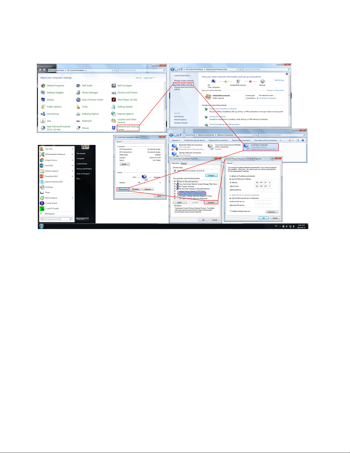
unique. For example, if the IP address of the Midas-M was set to 169.254.60.47 (the factory
default) then an appropriate IP address for the PC would be 169.254.60.42.
IP Address setting in Windows 7
Running the Web Server
In a web browser, set the URL to “http://xxx.xxx.xxx.xxx” where the “xxx” fields are replaced with
the IP address of the Midas-M.
Device's Overview
Display general information about the device and gas information of each channel.
From the home page, select General > Status > Overview.
The following image shows the information you can review from the Overview page.
Midas-M 42 User Manual
Page 43

Option Description
Overview page
Channels
General Device's general information
Summary
& Print
Reset
Alarm
Midas-M 43 User Manual
The gas information for each channel is displayed. The color bar under each box
shows the status of the channel.
A print-ready summary of device's information.
If alarms are occurring, reset the alarms.
Page 44

Log Review
On this page, you can view information about records in text format and as a detailed graph.
From the home page, select General > Event History.
Midas-M 44 User Manual
Page 45
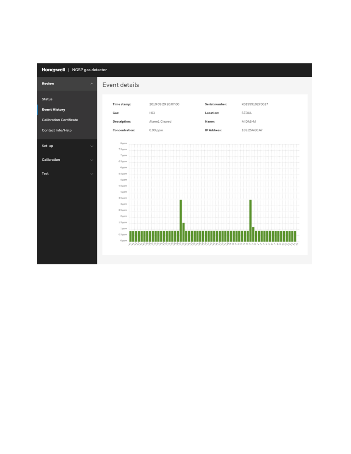
The following graph shows detailed information about the selected log. The graphic displays the
gas concentration before and after a specific time from when the event occurred.
Midas-M 45 User Manual
Page 46
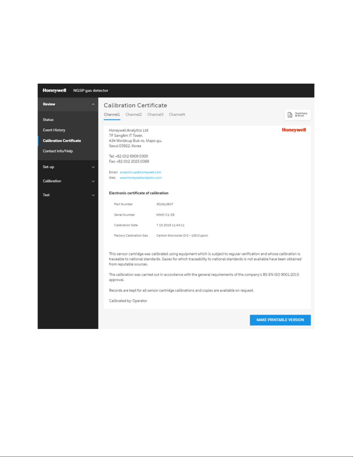
Get a Calibration Certificate
Get the calibration information implemented on a per-channels basis when the device was
manufactured.
On this page, you can view information from the producer, device, and name of the calibrator.
From the home page, select General > Calibration Certificate.
Midas-M 46 User Manual
Page 47
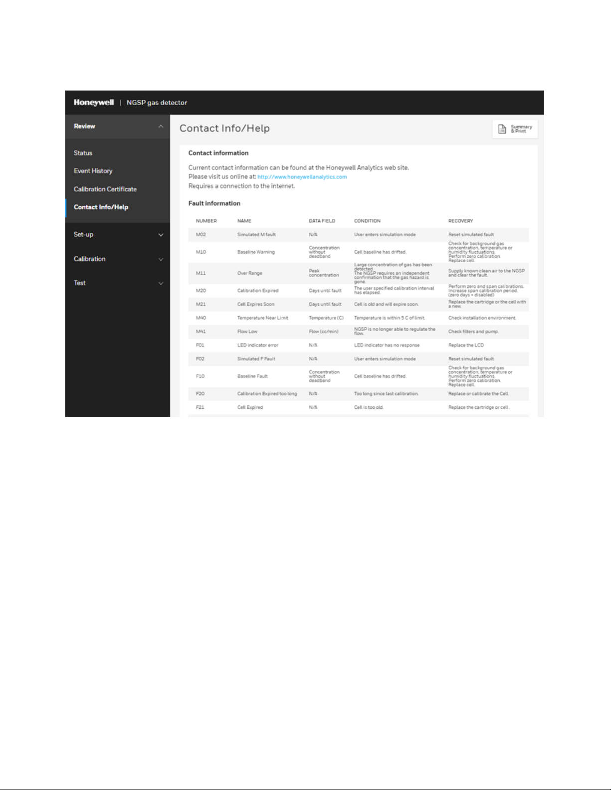
Get Fault and Contact information
To get fault's list and Contact info, select General > Contact Info/Help.
Midas-M 47 User Manual
Page 48

Set up Gas and Alarm
Set up gas detection and alarm set for each channel.
On the home page, select Set-up>Gas/Alarm.
1. Set the desired channel.
2. Gas: Set the gas you want to detect on each channel. Gas-name and K-factor (weight value
for gas value) can be set only for User-gas.
Note: You cannot set the range.
3. Set the concentration at which Alarm1 occurs.
4. Set the concentration at which Alarm2 occurs.
5. Enter the Dead band.
6. Enter the Alarm delay. When an alarm condition is reached, an alarm occurs at a delayed
time.
7. Set up Latching in an alarm situation.
8. Set the time for calibrating the progress alarm.
9. Click Accept.
Midas-M 48 User Manual
Page 49

Configure the Relays
Set the Alarm and Fault relays.
On the home page, select Set-up > Relays.
You can set the relays as follows:
l Relay configuration: Set the operation conditions for Relay 1,2,3.
l Alarm relay: Set whether to generate alarm relay.
l Fault relay: Set whether to generate a fault relay.
Midas-M 49 User Manual
Page 50

Set up the 4-20 mA
Set the ratio of mA and concentration values.
On the home page, select Set-up > 4-20 mA.
You can set the 4-20MA as follows:
l Channel: Select the channel to set.
l Output 4 mA: Set the gas concentration for 4mA.
l Output 20 mA: Set the gas concentration for 20mA.
Midas-M 50 User Manual
Page 51
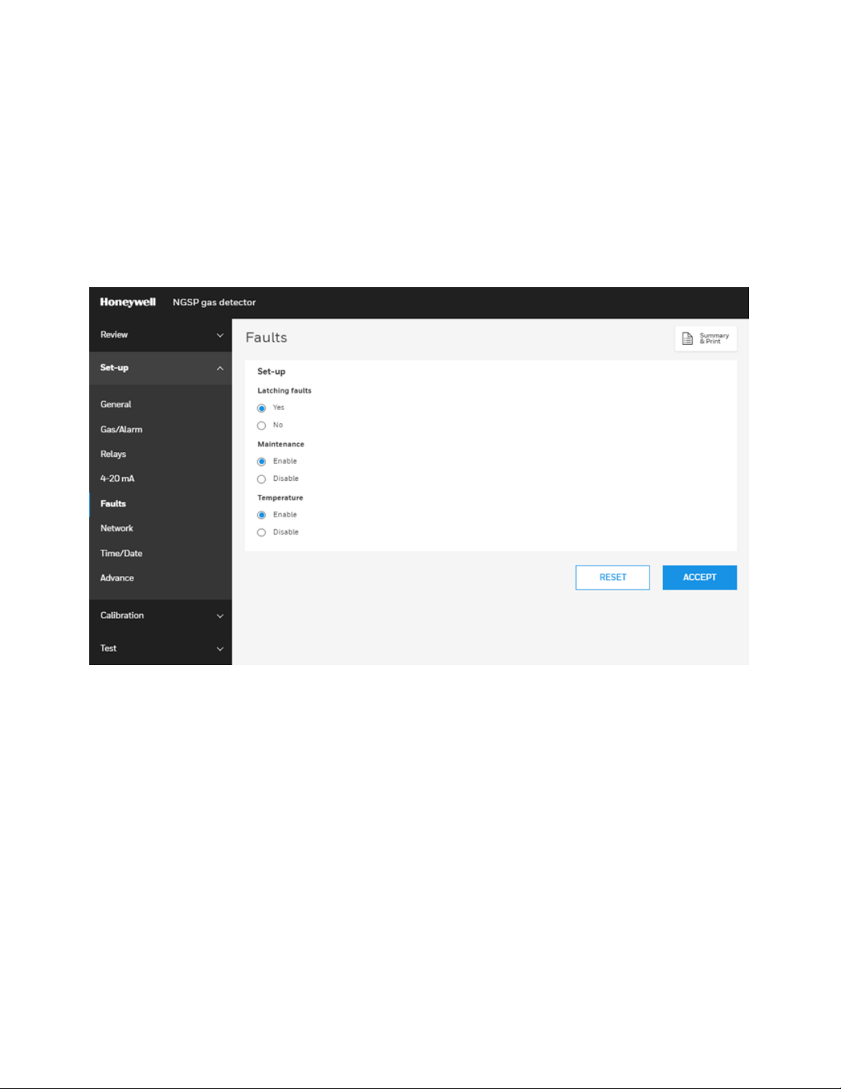
Set up Faults
Set a Fault Occurrence
On the home page, select Set-up > Faults.
You can set the faults as follows:
l Latching faults: Set whether to perform latching when faults occur.
l Maintenance: Set whether to generate a fault for maintenance
l Temperature: Set whether to generate a fault for Temperature. This option is enabled if the
Maintenance setting is allowed too.
Midas-M 51 User Manual
Page 52

Set up the Network
Set an specific network.
On the home page, select Set-up > Network.
You can set the network as follows:
l Obtain IP: You can select whether Manual or Automatic.
l Ip address, Subnet, and Default gateway are enabled only when the Obtain IP option is set to
Manual.
l Hostname: Hostname setting.
Midas-M 52 User Manual
Page 53

Set up the Time and Date
Set the time and date.
On the home page, select Set-up > Time/Date.
You can set the Time and Date in a 24 hour format and synchronize it with the computer.
Midas-M 53 User Manual
Page 54

Turn Channels on/OFF
You can turn ON/OFF an individual channel.
On the home page, select Set-up > Advance.
Zero Calibration
Perform Zero calibration for a specific channel or all at once.
1. On the home page, select Calibration > Zero Calibration.
2. Select the channel or channels to zero calibrate, and then click Start.
Midas-M 54 User Manual
Page 55

3. Wait until the gas reading is stable, and then click Accept.
Midas-M 55 User Manual
Page 56

4. On the Result window the status of zero calibration is displayed. Click Finish.
5. In the Inhibit window you have the option to check Inhibit, and then click Accept.
Span Calibration
Perform an span calibration for each channel of the device.
1. On the home page, select Calibration > Span Calibration.
2. On the Span calibration page, you can select the gas, the gas type, and the target
concentration.
3. Click Start and then follow screen instructions.
Midas-M 56 User Manual
Page 57
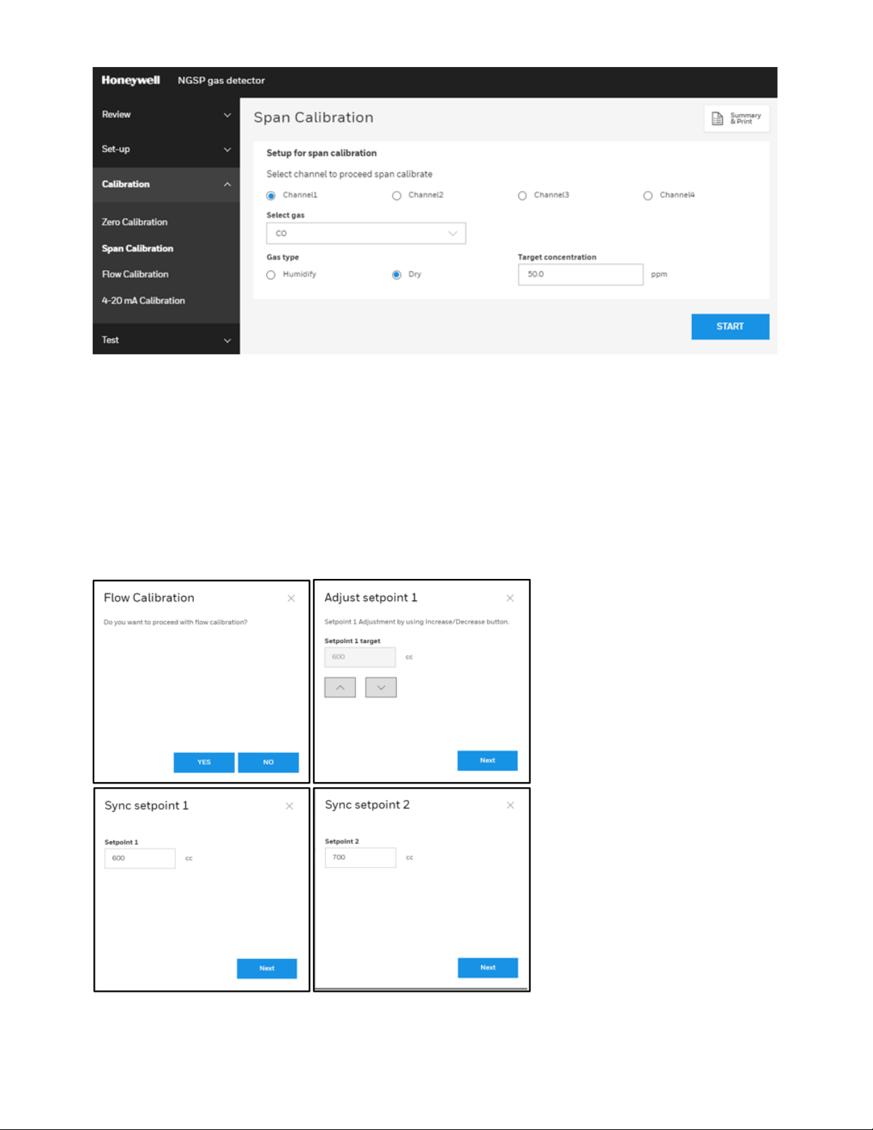
Flow Calibration
Calibrate the amount of gas entering the device.
On the home page, select Calibration > Flow Calibration, and then follw screen instructions. You
can adjust setpoints,and sync setpoints.
Midas-M 57 User Manual
Page 58
Calibrate 4-20 mA
Perform a mA calibration for each channel of the device.
1. On the home page, select Calibration > 4-20mA Calibration.
2. Select a channel, and then click Start.
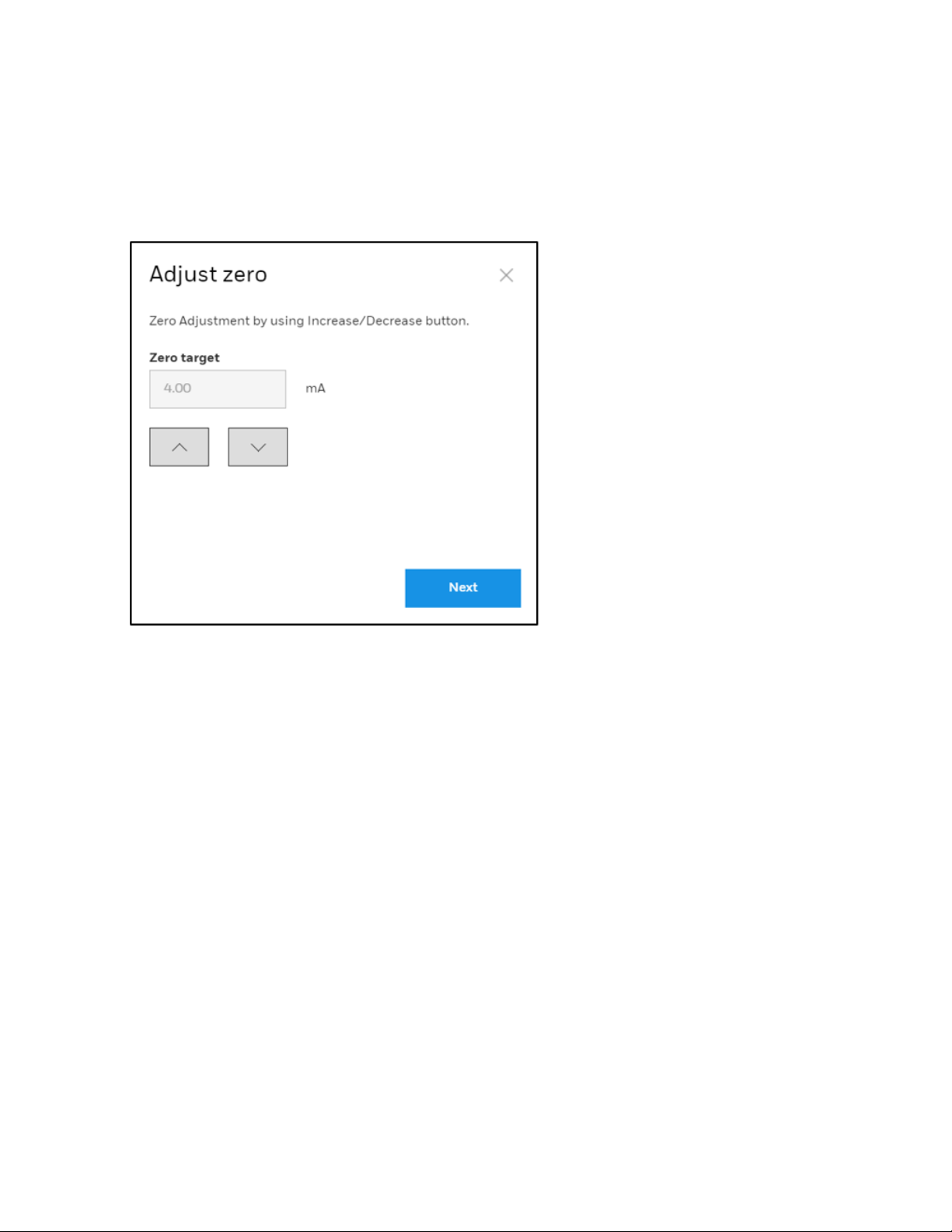
3. Increase or decrease the mA value, and then click Next to Zero calibration (4 mA).
Midas-M 58 User Manual
Page 59

4. Increase or decrease the mA value, and then click Next to calibrate the span (20mA).
Perform a Bump Test
Perform a Bump Test on diverse channels.
1. On the home page, select Test > Bump Test.
2. Click Enter Bump Test Mode.
3. Optional Step. You can click Stop Bump Test to cancel the procedure.
Midas-M 59 User Manual
Page 60
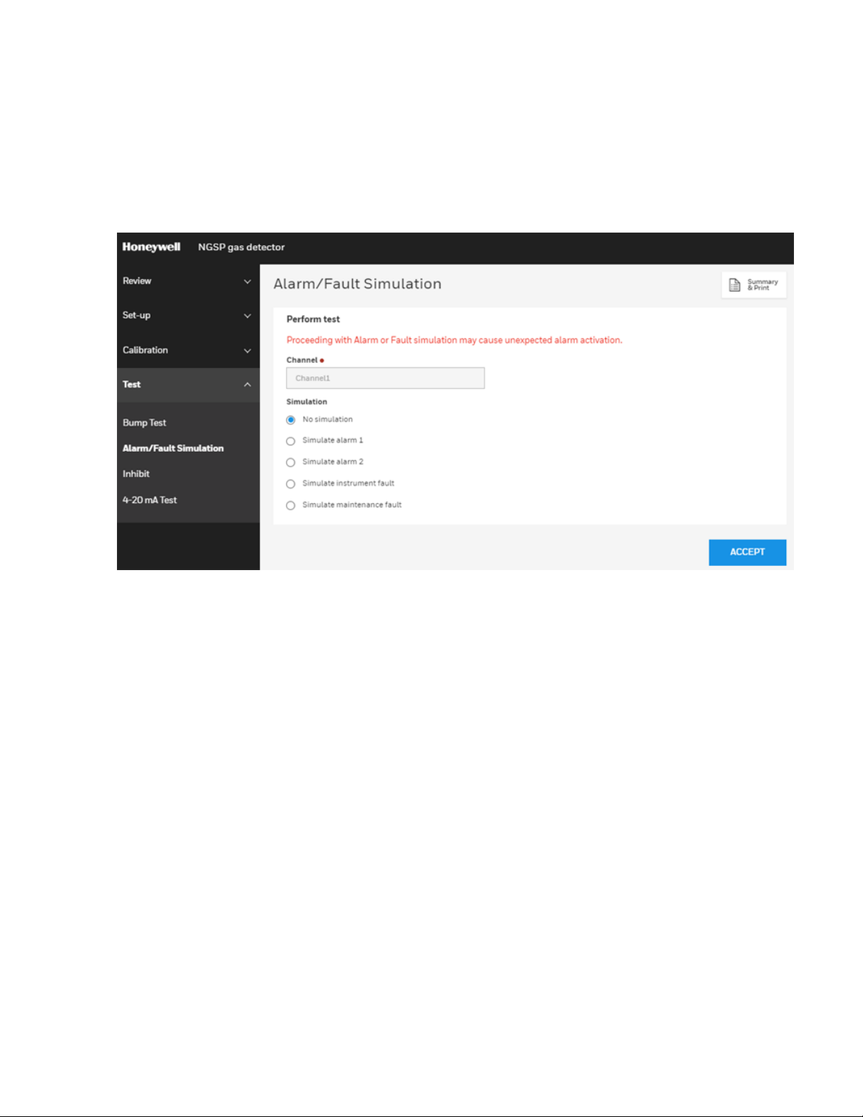
Perform an Alarm or Fault Simulation
Simulate function for testing alarm faults.
1. On the home page, select Test > Alarm/Fault Simulation.
2. Select a Channel.
3. Select whether the simulation should be on an Alarm or a Instrument fault.
4. Click Accept.
Midas-M 60 User Manual
Page 61
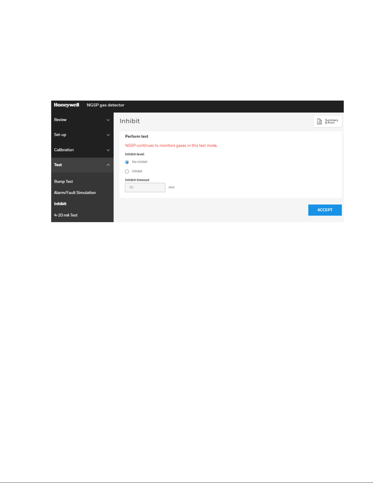
Perform Inhibit Test
Enable or disable the inhibit state.
1. On the home page, select Test > Inhibit.
2. From the Inhibit level option, select No inhibit or Inhibit.
3. Select the Inhibit timeout in minutes.
4. Click Accept.
Midas-M 61 User Manual
Page 62
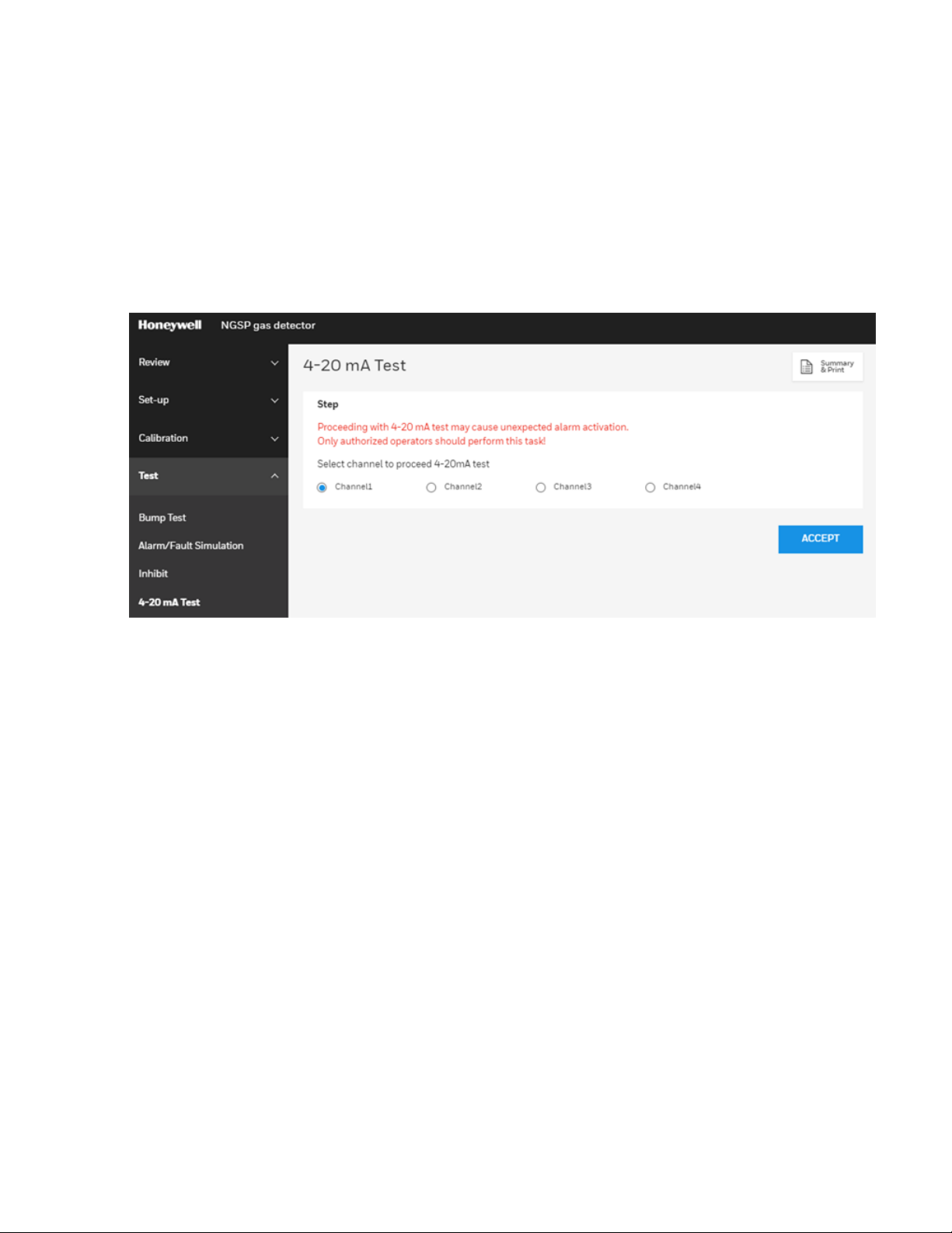
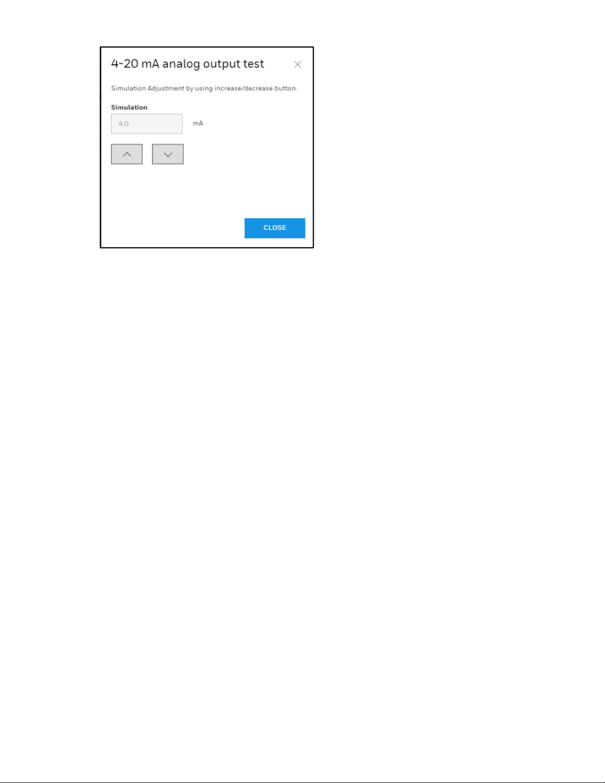
Perform a 4-20mA test
Test the mA value on a channel.
Note: The 4-20 MA test may cause unexpected alam activation. Only authorized operators should
perform this task.
1. On the home page, select Test > 4-20 mA Test.
2. Select a Channel.
3. Click Accept.
4. Increase or decrease the mA value.
5. Click Close.
Midas-M 62 User Manual
Page 63
Midas-M 63 User Manual
Page 64

Page 65

CHAPTER
Maintenance
4
Midas-M is a fully serviceable product designed with modular components that can be readily
replaced by trained service personnel so as to minimize the time that the gas detector is not
available.
External in-line air filters should be replaced every three months or more frequently if the system
is sampling in environments that have high levels of particulate matter or very acidic / wet
atmospheres. Similarly, the internal particulate filter should be replaced every two years or more
frequently if the sample lines are prone to heavy contamination. Refer to the following table.
Every sensor cartridge is shipped with a 2 years warranty. All sensor cartridges are factory
calibrated to traceable national standards before shipment to the end user.
Note that testing or calibrating with the wrong (incorrect, out of date, non-traceable) calibration
gases, calibration equipment, methods or operating conditions can actually damage the sensor
cartridge’s lifetime and alter the calibration adversely. Only qualified calibration technicians
should attempt to calibrate the Midas-M gas detector.
The internal pump module is designed to operate for a minimum of 24 months and it is
recommended that this pump module (part number MM-PM ) be replaced every 2 years.
Recommended maintenance schedule
Component Frequency
Pump 2 years or as needed
Internal filter 2 years or as needed
Part Number 780248, every 3-6 months
External Sample Line Filter
Leak Check Leak Check every 6 months or after replacing any component.
Bump Test 6 months
Flow Calibration Flow Calibrate after pump, internal and external filter replacement.
Part Number 1991-0147, every 3-6 months
Part Number 1830-0055, every 3-6 months
Midas-M 65 User Manual
Page 66

See the Gas Table for the correct filter requirement for your application.
NOTE
Every sensor cartridge warranty: Typically, two years depending on the sensor type. The Bias
battery will last only about six months. After replacement, allow at least a day for the
cartridge to reach equilibrium.
System Leak Check
When performing a leak check, the Midas-M must be placed in Inhibit mode to prevent false
concentrations or faults to be activated when plugging the Sample or Exhaust Lines. Example:
O2 (oxygen) – plugging of the ports causes the O2 levels within the Midas-M flow path to be
depleted as the sample becomes stagnant. The result is the concentration levels begin to fall and
trigger the alarms for the O2 depletion.
1. Place the Midas-M into Inhibit.
2. Plug the Inlet Sample line.
3. The flow meter indicators will begin to drop and ultimately disappear within seconds.
4. Continue to keep the port plugged until the Midas-M reports an “F41” (Flow Fail) –
approximate time to fault is 24 seconds.
5. Remove the plug.
6. Allow 15 seconds or so to allow the Midas-M flow to stabilize then clear the fault by pressing
and holding ‘X’
7. Plug the Outlet Exhaust line.
8. The flow meter indicators will begin to drop and ultimately disappear within seconds.
9. Continue to keep the port plugged until the Midas-M reports an “F41” (Flow Fail) –
approximate time to fault is 24 seconds.
10. Remove the plug.
Midas-M 66 User Manual
Page 67

11. Allow 15 seconds or so to allow the Midas-M flow and concentrations to stabilize then clear
the fault by pressing and holding ‘X’
12. Return the unit to the Monitoring Mode.
Midas-M 67 User Manual
Page 68

Page 69

CHAPTER
5
Learn from about strategic information related to the Honeywell Midas®-M Detector.
Additional Information
EU Directive 2012/19/EU: Waste Electrical and Electronic Equipment (WEEE)
This symbol indicates that the product must not be disposed of as general industrial
or domestic waste. This product should be disposed of through suitable WEEE disposal facilities.
For more information about disposal of this product, contact your local authority, distributor or
the manufacturer.
Midas-M 69 User Manual
Page 70

Troubleshooting and Fault Diagnosis
General troubleshooting guide and specific fault code table for the Midas-M gas detector.
Fault code descriptions
Number Date Data Field Condition Recovery
M02
M10
M11 Over Range
M20
Simulated M
fault
Baseline
warning
Calibration
expired
N/A
Concentration
without
Deadband
Peak
concentration
Days until
fault
User enters simulation
mode
Cell baseline has drifted.
Large concentration of
gas has been detected.
The Midas-M requires
an independent
confirmation that the gas
hazard is gone.
The user-specified
calibration interval has
elapsed.
Reset simulated fault
Check for background
gas concentration,
temperature, or
humidity fluctuations.
Perform zero
calibration. Replace
cell.
Supply clean air to the
Midas-M and clear the
fault.
Perform zero and span
calibrations. Increase
span calibration
period. (zero days =
disabled)
M21
M40
M41 Flow Low Flow (cc/min)
F01
F02
Midas-M 70 User Manual
Cell expires
soon
Temperature
Near Limit
LED
indicator
error
Simulated F
Fault
Days until
fault
Temperature
(C)
N/A
N/A
Cell is old and will expire
soon.
Temperature is within 5
C of limit.
Midas-M is no longer
able to regulate the flow.
LED indicator has no
response.
User enters simulation
mode
Replace the cartridge
or the cell with a new.
Check installation
environment.
Check filters and
pump.
Replace the LCD
Reset simulated fault
Page 71

Number Date Data Field Condition Recovery
Check for background
gas concentration,
F10
Baseline
Fault
Concentration
without
Deadband
Cell baseline has drifted.
temperature or
humidity fluctuations.
Perform zero
calibration. Replace
cell.
Calibration
F20
F21 Cell expired. N/A Cell is too old.
F40
F41 Flow Fail Flow (cc/min)
F42
F43
F44 LIT test fail N/A LIT test failed Check a flow path
Expired too
long.
Temperature
Limits
Exceeded
Pump
Memory
error
Pump
absent
N/A
Temperature
(C)
N/A
N/A There is no pump
Too long since last
calibration.
Temperature is out of
limit.
Flow < 70% of nominal
for 24 seconds
Pump memory has no
response or corrupted
data
Replace or calibrate
the Cell.
Replace the cartridge
or cell.
Check installation
environment.
Check filters and
pump.
Reboot
Device Power off and
then insert the pump
F50 Cell Failure N/A
F51
F52
F53
F54
Midas-M 71 User Manual
Cell comm.
Failure
Cell memory
error
Cell Memory
Invalid
Cell IR
N/A
N/A
N/A Checksum error. Replace cell
N/A
Reflex test fail of toxic
cell
It has failed to
communicate with IR
cell
Cell memory has no
response or corrupted
data
Cell IR voltage is out of
Replace cell
Replace IR cell
Replace cell
Replace cell
Page 72

Number Date Data Field Condition Recovery
voltage error range
F60
F61
F62 No valid cell N/A
F63
F64
F65
F66
The absent
cartridge
Cartridge
wrong type
Cartridge
Memory
Invalid
Cartridge
app Memory
Invalid
Cartridge
3.3V error
Cartridge 5V
error
N/A No communications.
Cell ID
N/A Checksum error. Reboot
N/A Checksum error. Replace cartridge.
Voltage
Voltage
Cartridge has one or
more empty channel
Cartridge has no valid
cell
Cartridge 3.3V is out of
range
Cartridge 5V is out of
range
Reset cartridge.
Replace cartridge.
Replace cartridge.
Replace cartridge.
Replace cartridge.
Replace cartridge.
F67
F80
F81
F82
F83
F84
Cartridge
app failed
Transmitter
NOR flash
error
Transmitter
memory
invalid
Transmitter
memory
comm. Error
Transmitter
app memory
invalid
Transmitter
3.3V error
N/A
N/A No communication
N/A Checksum error. Reboot
N/A Communication failed Reboot
N/A Checksum error.
Voltage
Cannot start cartridge
app
Transmitter 3.3V is out
of range
Update the latest
cartridge app
Replace the
transmitter
Replace transmitter or
update the latest
version
Replace Transmitter
Midas-M 72 User Manual
Page 73

Number Date Data Field Condition Recovery
F85
F86
Transmitter
24V error
Transmitter
5V error
Voltage
Voltage
Transmitter 24V is out of
range
Transmitter 5V is out of
range
Replace Transmitter
Replace Transmitter
Midas-M 73 User Manual
Page 74

Specifications
Transmitter Dimension
Specifications
Size (unit with
Cartridge)
Weight Transmitter
Weight Cartridge
Optional Relay Dimension
Size "137 mm (H) X 84 mm (W) X 41 mm (D) (5.39 X 3.31 X 1.61 in)"
Weight 0.31 kg (0.68 lb)
Power Requirements
Operating
Voltage
"Operating
Voltage with
Power over
Ethernet (PoE)"
"136 mm (H) X 83 mm (W) X 152 mm (D) (5.35 X 3.27 X 5.98 in)"
1.3 kg (2.87 lb)
0.17 ~ 0.22 kg (0.38 ~ 0.49 lb) dependent on sensor type
24 VDC Nominal, -15 to +10% (20.4 to 26.4 VDC)
48 VDC PoE (IEEE 802.3af compliant)
Power Consumption
Transmitter unit
(normal
condition)
Transmitter unit
(full load
condition)
Transmitter with
Optional Relay
Outputs
Visuals
Relays in
Transmitter
1
2
Typ. 5W
≤ 11.45W
≤ 12.9 W
"Alarm, power, fault LEDs, and LCD with all the gas readings and
events. LEDs: Power (Green), Alarm 1 (Red), Alarm 2 (Red), Fault
(Yellow)"
"Alarm1, Alarm2, Fault Relays (3) rated 1.0 A @ 30Vdc or 0.5A @
125Vac Max 10uA @ 10mV minimum, configurable as normally open
or closed, latched or unlatched"
Midas-M 74 User Manual
Page 75

Relays in
Optional Relay
Specifications
"8 relays for Alarm1 and Alarm2 of each channel and a relay for
common fault rated 1.0 A @ 30Vdc or 0.5 A @ 125 Vac Max 10uA @
10mV minimum, configurable as normally open or closed, latched or
unlatched"
Analog
Digital
Communications Modbus / TCP Ethernet / Power over Ethernet (PoE)
Certification and Specification
Performance
Transport System
Flow Rate 600 mL/min
Transport Time 2 to 25 seconds maximum
Sample Line
Tubing
Tubing Length Up to 30 m (100 ft) with FEP tubing
3 wire sink, 3 wire source, or 4 wire fully isolated; 0 to 21 mA for each
channel
"CE marked Meets EN 50270:2015+AC:2016 and EN61000-64:2007+A1 ETL approved UL 61010-1:2012 Ed.3 IEEE 802.3af-2003"
Refer to Individual sensor datasheets
3.18 mm ID X 6.35 mm OD (0.125 X 0.25 in)
Exhaust Line
Tubing
Exhaust Length Up to 30 m (100 ft)
Ambient Point In line air filter required
Operating Temperature
Wiring Requirement
4-20mA 2 wire, 14 AWG maximum
Digital CAT5 Cable or equivalent: RJ45 connector
Gas Concentration Display and Interface
Instrument
Midas-M 75 User Manual
4.76 mm ID X 6.35 mm OD (0.188 X 0.25 in)
0°C to +40°C (32°F to 104°F)
"4-digit alphanumeric display with separate units, concentration bar
graph for each channel and other icon driven indicators 4 button
interface keypad"
Page 76

Specifications
Remote Internet browser access via Ethernet
Installation Details
Mounting Wall mounted using pre-drilled holes on chassis. Options for DIN rail.
Material
"Cover: Plastic (Polycarbonate) Chassis/Mounting Bracket: Zinc plated
steel Red frame : Liquid coated Aluminum "
Warranty
Transmitter unit 1 year
Sensor cartridge 2 years
1
Normal condition: (1) No gas alarm, (2) Without tube and pressure/vacuum
2
Full load condition: (1) All 4 channels gas alarm are on, (2) Maximum tubing length and
pressure/vacuum on the inlet/exhaust line
Midas-M 76 User Manual
Page 77
Ordering
This section contains details of how to order complete Midas-M detector and sensor cartridge
kits, separate transmitters and sensor cartridges as well as spares and accessories.
Transmitter
Part
Number
MMT-01 Midas-M 4-20mA Extractive Transmitter
MMT-02 Midas-M TCP/IP Modbus Extractive Transmitter
MMT-
T01
MMT-
T02
MMT-
B01
MMT-
B02
Description
Midas-M 4-20mA Extractive Transmitter with Tube
Midas-M TCP/IP Modbus Extractive Transmitter
with Tube
Midas-M 4-20mA Extractive Transmitter Bulk
Package (6pcs)
Midas-M TCP/IP Modbus Extractive Transmitter
Bulk Package (6pcs)
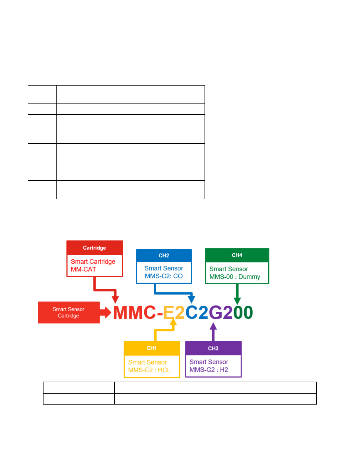
Cartridge
Part Number Description
MMC-xxxxxxxx Midas-M Sensor Cartridge with Smart Sensors
Midas-M 77 User Manual
Page 78

Smart Sensor Code
Dummy 00
Hydrogen Chloride (HCI) 0 - 8ppm, 2 years E2
Silane (SiH4) 0 -20 ppm, 2 years X2
Hydrogen (H2) 0 - 1000ppm, 2 years G2
Chlorine (CI2) 0 - 2ppm, 2 years L2
Ammonia(NH3) 0 - 100ppm, 2 years A2
Carbon Monoxide (CO) 0 - 100ppm, 2 years C2
Phosphine (PH3) 0 - 1200ppb, 2 years R2
Ozone (O3) 0 - 0.4ppm, 2 years U2
Oxygen (O2) 0 - 25%v/v, 3 years D2
Sulphur D ioxide (SO2) 0 - 8ppm, 2 years S2
Hydrogen Flouride (HF) 0 - 12ppm, 2 years Z2
Smart Sensor
Part
number
MMS-00 Midas-M Dummy Sensor
MMS-E2 Midas-M Hydrogen Chloride (HCI) 0 - 8ppm, 2 years
MMS-X2 Midas-M Silane(SiH4) 0 -20 ppm, 2 years
MMS-G2 Midas-M Hydrogen (H2) 0 - 1000ppm, 2 years
MMS-L2 Midas-M Chlorine (CI2) 0 - 2ppm, 2 years
MMS-A2 Midas-M Ammonia (NH3) 0 - 100ppm, 2 years
MMS-C2 Midas-MCarbon Monoxide (CO) 0 - 100ppm, 2
MMS-R2 Midas-MPhosphine (PH3) 0 - 1200ppb, 2 years
MMS-U2 Midas-MOzone (O3) 0 - 0.4ppm, 2 years
MMS-D2 Midas-MOxygen (O2) 0 - 25%v/v, 3 years
MMS-S2 Midas-M Sulphur Dioxide (SO2) 0 - 8ppm, 2 years
MMS-Z2 Midas-M HydrogenFlouride (HF) 0 - 12ppm, 2 years
Description
years
Accesories
Modules / Replacements
Midas-M 78 User Manual
Page 79

Part
number
MM-REL Midas-M R elay Module
MM-PM Midas-M Pump Module
MM-FIL Midas-M Filter Module
MM-FRT Midas-M Front Module
MM-B01 Midas-M 4-20mA Base Module
MM-B02 Midas-M TCP/IP Base Module
MM-M01 Midas-M 4-20mA Main Module
MM-M02 Midas-M TCP/IP Main Module
MM-CAT Midas-M Cartridge wo Smart Sensors
Mounting Accessories
Part number Description
MIDAS-A-036 MIDAS DIN Rail Mounting Kit
0235-0128 Flexible Conduit 21" - length
0235-0163 Flexible Conduit 27" - length
Description
MVIP3632-2A 2A 24VDC power supply in vented
NEMA 4 enclosure
MVIP3632-5A 5A 24VDC power supply in vented
NEMA 4 enclosure
Duct Sampling Adaptors
Part number Description
1283K1090 Duct Adapter for 1/4" O.D. tubing for 4-
16" round ducts
0235-0095 UnionFitting 1/4" tube, polypropylene
Tubing and ExternalSample Line Filters
Part number Description
780248 End of Line Particulate Filter, Disposable
1991-0147 End of LineParticulate F ilter for Corrosive
Gases, DisposableThis disposable filter
provides protection against particulate build
up in the sample line when monitoring for
Corrosive Gases.
0235-0095 Union Fitting- Use to connect disposable
filter to end of line
Midas-M 79 User Manual
Page 80

1830-0055 End of LineParticulate F ilter for Corrosive
Gases, Reusable This reusable filter housing
provides protection against particulate build
up in the sample line when monitoring for
Corrosive Gases. Replaceable filter element
(P/N 0235-1072) purchasedseparately
0235-1072 Replacement "Corrosive" Filter Elements
(pk 100) For use in 1830-0055 filter housing
102599 Tubing Teflon® FEP 1/4" OD x 1/8" ID
(Sample inlet) (Price per Foot)
1991-0136 Tubing Teflon® FEP 1/4" OD x 1/8" ID
(Sample Inlet) (100' continuouslength)
100440 Tubing Polypropylene 1/4" OD X 3/16" ID
(Exhaust) (Price per Foot)
1991-0137 Tubing Polypropylene 1/4" OD X 3/16" ID
(Exhaust) (100' continuouslength)
Midas-M 80 User Manual
Page 81

Page 82

Gas Table
Gas Name Formula
Hydrogen
Chloride
Boron
Trichloride
Dichlorosilane SiH2Cl2
Hydrogen
Bromide
Silane SiH4
HCI
BCI3
HBr
Range Resolution
0 - 8
ppm
0 - 8
ppm
0 - 8
ppm
0 - 8
ppm
0 - 20
ppm
0.05 ppm 1 ppm 2 ppm
0.05 ppm 1 ppm 2 ppm
0.05 ppm 1 ppm 2 ppm
0.05 ppm 1 ppm 2 ppm
0.01 ppm
Default
Alarm
1
2.5
ppm
Default
Alarm
2
5 ppm
Sensor
Part
Number
MMSE2
MMSE2
MMSE2
MMSE2
MMSX2
Maximum
Sensor
Warm-up
Time(minutes)
20 600 HCl 4 4 300 HCl 4-6 180 5
20 600 HCl 4 4 300 HCl 4-6 180 5
20 600 HCl 4 4 300 HCl 4-6 180 5
20 600 HCl 4 4.5 300 HCl 4-6 180 5
20 600 SiH4 10 10 300 SiH4 10 180 30
Flow
Rate
(cc/min)
Calibration
Gas
Calibration Bump Test
Conc.
Output
Equiv.
(ppm)
Exp
Time
(sec)
Recommended
Bump Test
Gas
Conc
(ppm)
Recommended
Max
Time
(sec)
Maximum
Sample Line
Length(m)
1
1
1
1
End of line filter
1991-0147
1991-0147
1991-0147
1991-0147
"780248, 19910147 or 18300055""780248,
1991-0147 or
1830-0055"
Disilane Si2H6
Hydrogen
(ppm)
Chlorine Cl2
Ammonia NH3
Carbon
Monoxide
Phosphine PH3
Ozone O3
H2
CO
0 - 20
ppm
0 1000
ppm
0 - 2
ppm
0 100
ppm
0 100
ppm
0 1200
ppb
0 - 0.4
ppm
0.05 ppm 1 ppm 2 ppm
5 ppm
0.01 ppm
0.5 ppm
0.5 ppm
5 ppb
0.002
ppm
125
ppm
0.25
ppm
12.5
ppm
12.5
ppm
150
ppb
0.05
ppm
250
ppm
0.5
ppm
25
ppm
25
ppm
300
ppb
0.1
ppm
MMSE2
MMSG2
MMSL2
MMSA2
MMSC2
MMSR2
MMSU2
20 600 SiH4 4 4 300 SiH4 10 180 10
10 600 H2 500 500 300 H2 500 180 30
10 600 Cl2 1 1 300 Cl2 1 180 10
10 600 NH3 50 50 300 NH3 50 180 10
10 600 CO 50 50 300 CO 50 180 30
20 600 PH3
10 600 O3 0.2 0.2 300 NO2
600
ppb
600
ppb
300 PH3 600 180 30
2
1 180 5 1830-0055
"780248, 19910147 or 18300055"
"780248, 19910147 or 18300055"
1991-0147 or
1830-0055
"780248, 19910147 or 18300055"
"780248, 19910147 or 18300055"
"780248, 19910147 or 18300055"
Oxygen
Proficiency &
Deficiency
Sulfur Dioxide SO2
Hydrogen
O2
HF
0 - 25
%vol
0 - 8
ppm
0 - 12
0.1 %vol
0.05 ppm 1 ppm 2 ppm
0.05 ppm
23.5
%vol
1.5
19.5
%vol
3 pmm
MMSD2
MMSS2
MMS-
30 600 O2 Air
10 600 SO2 4 4 300 SO2 4 180 30
20 600 HF 6 6 300 Cl2 10 180 5
20.9
%vol
300 O2 Air 180 30
"780248, 19910147 or 18300055"
1991-0147 or
1830-0055
1
1991-0147 or
Page 83

Default
Alarm
Gas Name Formula
Range Resolution
1
Fluoride ppm ppm Z2 1830-0055
Default
Alarm
2
Sensor
Part
Number
Maximum
Sensor
Warm-up
Time(minutes)
Flow
Rate
(cc/min)
Calibration
Gas
Calibration Bump Test
Conc.
Output
Equiv.
(ppm)
Exp
Time
(sec)
Recommended
Bump Test
Gas
Conc
(ppm)
Max
Time
(sec)
Recommended
Maximum
Sample Line
Length(m)
End of line filter
Boron
Trifluoride
Tungsten
Hexafluoride
Bump Testing Notes:
As an alternative, the actual target gas can always be used instead of a cross-sensitive gas.
Higher concentrations than the recommended ones can be used if necessary, but extra time may be needed for the reading to recover to zero.
IMPORTANT: this should only be done once to avoid the danger of poisoning the sensor.
BF3
WF6
1
Recommended to keep the sample lines as short as possible where the RH condition at the sample point is high (above %50 RH); there will be some sample loss due to absorption onto the
sample line.
2
An ozone generator can be used instead of 1 ppm NO2.
0 - 8
ppm
0 - 12
ppm
0.05 ppm 1 ppm 2 ppm
0.05 ppm
1.5
ppm
3 ppm
MMSZ2
MMSZ2
20 600 HF 4 5.2 300 Cl2 5 180 5
20 600 HF 6 6 300 Cl2 10 180 5
1
1
1991-0147 or
1830-0055
1991-0147 or
1830-0055
Page 84

Combination Index
HCl
(MMSE2)
SiH4
(MMSX2)
H2
(MMSG2)
Cl2
(MMSL2)
NH3
(MMSA2)
CO
(MMSC2)
HCl
(MMSE2)
NO NO NO
SiH4
(MMSX2)
H2
(MMSG2)
Cl2
(MMSL2)
NH3
(MMSA2)
NO
NO
CO
(MMSC2)
PH3
(MMSR2)
O3
(MMSU2)
O2
(MMSD2)
SO2
(MMSS2)
HF H
(MMSZ2)
PH3
(MMSR2)
O3
(MMSU2)
O2
(MMSD2)
SO2
(MMSS2)
HF H
(MMSZ2)
NO
NO
NO
Midas-M 84 User Manual
Page 85

Reflex
Midas-M uses patented Honeywell Analytics technology to continuously monitor the health
check status of specific electrochemical cells and alert the user if a cell enters a variety of fault
conditions (such as open or short circuit etc.) which would leave the cell unable to detect gas
and raise an appropriate alarm signal.
REFLEX® overcomes this unseen failure mode by applying periodically a special electronic pulse
to the cell and reviewing the ‘echo’ from the cell as it responds to the applied signal. If the cell is
deteriorating within certain pre-set limits based on the received signals then Midas-M will
decrease the REFLEX sampling interval in order to establish the actual viability of the cell. Within
a relatively short time, Midas-M will be able to alert the user via fault codes that the
electrochemical cell is likely to be requiring replacement and is possibly unable to correctly
detect gas.
REFLEX is not required for pellistors, IR, oxygen electrochemical cell or bias electrochemical
cell as these sensor cartridges provide alternative electronic means to indicate open circuits and
other sensor cartridge damage issues.
Midas-M 85 User Manual
Page 86

A Modbus/TCP Interface
The Midas-M gas detector can report concentration information in a variety of formats
including relay contact closure, an analog 4-20 mA loop, Ethernet/ IP/HTML web pages and via
the Modbus/TCP networking protocol. This section defines the format of data in Modbus/TCP
registers. More information about Modbus/TCP can be obtained from www. modbus.org.
The Midas-M is a Modbus/TCP “server” as defined in the MODBUS Application Protocol
Specification V1.0 . It supports command 03 (“read holding registers”) for registers 40001 to
40122 as listed in the following table.
The Midas-M reports floating-point concentration numbers in little-endian or Intel format. This
is scaled in units of ppm for gasses which have display units of ppm or ppb. For other display
units the concentration is scaled directly in display units. This applies to registers Gas
Concentration and Alarm Threshold.
The Midas-M fills 122 Modbus/TCP holding registers as listed in Table 1. The Monitoring Status
register is a concise summary of Midas-M status. The other registers provide more complete
information.
Midas-M Modus Register Map
Midas-M Modbus Register Map : Register 40001 is mapped with base address (zero)
(If channel is disabled, channel information is 0).
ModBus
Register
Number
Device St atus
40001 Reserved for
Information R/W
future
expansion
Data
Type
R 2
Data
Size
Description Note
(Byte)
Holding Register
Midas-M 86 User Manual
Page 87

ModBus
Register
Number
Information R/W
Data
Type
Data
Size
(Byte)
Description Note
40002 Monitoring
Status
40003 Alarm State R u16 2 bit 0 : Ch1 Alarm 1 active bit 1 : Ch1
R u16 2 bit 0 : Warmup bit 1 : Inhibit Mode bit 2
: Alarm/Fault simulation bit 3 : 4-20mA
calibration mode bit 4 : 4-20mA test
mode bit 5 : Flow calibration mode bit
6 : LIT calibration mode (Reserved) bit
7 : LIT Enabled (Reserved) bit 8 : Gas
calibration mode bit 9 : Gas bump test
mode bit 10 : Alarm bit 11 : Fault bit 12
~ 15 : for future expansion
Alarm 2 activebit 2 : Ch2 Alarm 1
active bit 3 : Ch2 Alarm 2 active bit 4 :
Ch3 Alarm 1 activebit 5 : Ch3 Alarm 2
active bit 6 : Ch4 Alarm 1 active bit 7 :
Ch4 Alarm 2 activebit 8~15 : for future
expansion
40004 Fault State R u16 2 bit 0 : Ch1 fault active bit 1 : Ch2 fault
active bit 2 : Ch3 faultactive bit 3 : Ch4
fault activebit 4 : Device fault active bit
5~15 : for future expansion
40005 Top Fault R u16 2 Number of
most important
active fault
Midas-M 87 User Manual
Page 88

ModBus
Register
Number
Information R/W
Data
Type
Data
Size
(Byte)
Description Note
40006 Channel
Enabled State
40007 to
40008
40009 to
40010
Gas
Concentration
Ch1
Gas
Concentration
Ch2
R u16 2 This is the bit
representation
information of
channel
enabled. If
dummycellis
attached or
channel is
disabled bit
value is set.
R f32 4 Value in float
R f32 4 Value in float
bit 0 : Ch1 Dummy cell bit 1 : Ch1
Disabled bit 2 : Ch1 Reservedfor
futher expansion bit 3 : Ch2 Dummy
cellbit 4 : Ch2 Disabled bit 5 : Ch2
Reserved for futher expansion bit 6 :
Ch3 Dummy cell bit 7 : Ch3 Disabled
bit 8 : Ch3 Reserved for futher
expansion bit 9 : Ch4 Dummy cell bit
10 : Ch4 Disabled bit 11 : Ch4
Reserved for futher expansion bit
12~15 : for future expansion
40011 to
40012
40013 to
40014
40015 to
40016
40017 to
40018
40019 to
40020
40021 to
40022
Gas
Concentration
Ch3
Gas
Concentration
Ch4
Gas
Concentration
Ch1
Gas
Concentration
Ch2
Gas
Concentration
Ch3
Gas
Concentration
Ch4
R f32 4 Value in float
R f32 4 Value in float
R u32 4 Value in fixed
point
R u32 4 Value in fixed
point
R u32 4 Value in fixed
point
R u32 4 Value in fixed
point
Conversion equation: ppm value =
Value * 1/10 DECP
Conversion equation: ppm value =
Value * 1/10 DECP
Conversion equation: ppm value =
Value * 1/10 DECP
Conversion equation: ppm value =
Value * 1/10 DECP
Midas-M 88 User Manual
Page 89

ModBus
Register
Number
Information R/W
Data
Type
Data
Size
(Byte)
Description Note
40023 Decimal Point
Indicator
40024 Heat beat
Counter
40025 to
40026
Device
Maintenance
Fault
R u16 2 Decimalpoint
indicator of
DisplayGas
Concentration
R u16 2 Systemtime in
seconds.
Range of this
value is from 0
to 59
R u32 4 This is the bit
order
representation
of the
maintenance
fault status.If
any fault exists
this will take a
value in each
bit. if any
maintenance
fault exists, this
will take a
value zero.
The meaning
of bit will be
described as
fault code in
more detail
bit 0 ~ 2 : Ch1 Decimalpoint indicator
(0, 1, 2, 3) bit 3 ~ 5 : Ch2 Decimal
point indicator (0, 1, 2, 3) bit 6 ~ 8 :
Ch3 Decimalpoint indicator (0, 1, 2, 3)
bit 9 ~ 11 : Ch4 Decimal point
indicator (0, 1, 2, 3) bit 12~15 : for
future expansion
bit 0 : Simulated Maintenance Fault
(m02) bit 1 : Flow Warning (m41) bit
2~31 : for future expansion
Midas-M 89 User Manual
Page 90

ModBus
Register
Number
Information R/W
Data
Type
Data
Size
(Byte)
Description Note
40027 to
40028
Device
Instrument
Fault
R u32 4 This is the bit
order
representation
of the
instrument
fault status.If
any fault exists
this will take a
value in each
bit. if any
instrument
fault exists, this
will take a
value zero.
The meaning
of bit will be
described as
fault code in
more detail
bit 0 : LCD Fault (F01) bit 1 :
Simulated Instrument Fault (F02) bit 2
: Reservedfor future expansion bit 3 :
Flow Fail (F41) bit 4 : Pump EEPROM
(F42) bit 5 : Pump Absent (F43) bit 6 :
LIT Fail (F44) (Reserved) bit 7 :
Cartridge Absent(F60) bit 8 : Catridge
Wrong Type (F61) bit 9 : Cartridge No
valid cell (F62) bit 10 : Catridge
EEPROM (F63) bit 11 : Catridge
Flash (F64) bit 12 : Catridge Power
3.3v (F65) bit 13 : Catridge Power 5v
(F66) bit 14 : Catridge Application Fail
(F67) bit 15 : T ransmitter Nor Flash
(F80) bit 16 : T ransmitter EEPROM
Corrupted (F81) bit 17 : Tr ansmitter
EEPROM Com Fail (F82) bit 18 :
Transmitter Flash(F83) bit 19 :
Transmitter Power 3.3v (F84) bit 20 :
Transmitter Power 24v (F85) bit 21 :
Transmitter Power 5v (F86) bit 22~31
: for future expansion
40029 Relay Status R u16 2 The meaning
of bit : Value 0
is Deenergized
Value 1 is
Energized
40030 Temperature
in Celsius (oC)
R s16 2 Temperature
bit 0 : InternalRelay 1 energizedbit 1 :
InternalRelay 2 energized bit 2 :
InternalRelay 3 energized bit 3 : for
future expansion bit 4 : ExternalRelay
Fitted bit 5 : External Relay 1
energized (Ch1 alarm1) bit 6 :
External Relay 2 energized(Ch1
alarm2) bit 7 : External Relay 3
energized (Ch2 alarm1) bit 8 :
External Relay 4 energized(Ch2
alarm2) bit 9 : External Relay 5
energized (Any fault) bit 10 : External
Relay 6 energized (Ch3 alarm1) bit 11
: ExternalRelay 7 energized (Ch3
alarm2) bit 12 : External Relay 8
energized (Ch4 alarm1) bit 13 :
External Relay 9 energized(Ch4
alarm2) bit 14~15 : for future
expansion
Midas-M 90 User Manual
Page 91

ModBus
Register
Number
Information R/W
Data
Type
Data
Size
(Byte)
Description Note
40031 Flow rate in
cc/minute
40032 ~
40037
Channel 1 Information
40038 Gas Selection R u16 2 bit 0 - 7 : GasID bit 8 - 15 : Cell ID
40039 to
40040
40041 to
40042
40043 Measuring
Reserved for
future
expansion
Alarm1
threshold
Alarm2
threshold
units
R u16 2 Current pump
flow
R u16 12
R/W f32 4
R/W f32 4
R u16 2 Concentration
units
0 : N/A 1 : mA 2 : %LEL 3 : % volume4
: ppb 5 : ppm 6 : mg/m37 ~ 15:
reserved
40044 Alarm Status R u16 2 bit 0 : Alarm 1 active bit 1 : Alarm 2
active
40045 Fault Status R u16 2 This is the bit
order
representation
of the channel
fault status.If
any fault exists
this will take a
value in each
bit.
bit 0 : Baseline Warning (m10) bit 1 :
Overrange Warning (m11) bit 2 :
Calibration Expire Soon (m20) bit 3 :
Cell Expire Soon (m21) bit 4 :
Temperature Warning (m40) bit 5 :
Baseline Fault (F10) bit 6 : Calibration
Expired (F20) bit 7 : Cell Expired
(F21) bit 8 : Temperature Exceeded
(F40) bit 9 : Cell Failure Refelex (F50)
bit 10 : Cell Failure IR Comm. (F51) bit
11 : Cell EEPROM Read Error (F52)
bit 12 : Cell EEPROM Corrupted
(F53) bit 13 : Cell Failure IR Volt.
(F54) bit 14~15 : : for future expansion
Midas-M 91 User Manual
Page 92

ModBus
Register
Number
Information R/W
Data
Type
Data
Size
(Byte)
Description Note
40046 Cell life
remaining
days
40047 ~
40049
Channel 2 Information
40050 Gas Selection R u16 2 bit 0 - 7 : GasID bit 8 - 15 : Cell ID
40051 to
40052
40053 to
40054
40055 Measuring
Reserved for
future
expansion
Alarm1
threshold
Alarm2
threshold
units
R s16 2 Days of cell
remains
R 6
R/W f32 4
R/W f32 4
R u16 2 Concentration
units
0 : N/A 1 : mA 2 : %LEL 3 : % volume4
: ppb 5 : ppm 6 : mg/m37 ~ 15:
reserved
40056 Alarm Status R u16 2 bit 0 : Alarm 1 active bit 1 : Alarm 2
active
40057 Fault Status R u16 2 This is the bit
order
representation
of the channel
fault status.If
any fault exists
this will take a
value in each
bit.
bit 0 : Baseline Warning (m10) bit 1 :
Overrange Warning (m11) bit 2 :
Calibration Expire Soon (m20) bit 3 :
Cell Expire Soon (m21) bit 4 :
Temperature Warning (m40) bit 5 :
Baseline Fault (F10) bit 6 : Calibration
Expired (F20) bit 7 : Cell Expired
(F21) bit 8 : Temperature Exceeded
(F40) bit 9 : Cell Failure Refelex (F50)
bit 10 : Cell Failure IR Comm. (F51) bit
11 : Cell EEPROM Read Error (F52)
bit 12 : Cell EEPROM Corrupted
(F53) bit 13 : Cell Failure IR Volt.
(F54) bit 14~15 : : for future expansion
Midas-M 92 User Manual
Page 93

ModBus
Register
Number
Information R/W
Data
Type
Data
Size
(Byte)
Description Note
40058 Cell life
remaining
days
40059 ~
40061
Channel 3 Information
40062 Gas Selection R u16 2 bit 0 - 7 : GasID bit 8 - 15 : Cell ID
40063 to
40064
40065 to
40066
40067 Measuring
Reserved for
future
expansion
Alarm1
threshold
Alarm2
threshold
units
R s16 2 Days of cell
remains
R 6
R/W f32 4
R/W f32 4
R u16 2 Concentration
units
0 : N/A 1 : mA 2 : %LEL 3 : % volume4
: ppb 5 : ppm 6 : mg/m37 ~ 15:
reserved
40068 Alarm Status R u16 2 bit 0 : Alarm 1 active bit 1 : Alarm 2
active
40069 Fault Status R u16 2 This is the bit
order
representation
of the channel
fault status.If
any fault exists
this will take a
value in each
bit.
bit 0 : Baseline Warning (m10) bit 1 :
Overrange Warning (m11) bit 2 :
Calibration Expire Soon (m20) bit 3 :
Cell Expire Soon (m21) bit 4 :
Temperature Warning (m40) bit 5 :
Baseline Fault (F10) bit 6 : Calibration
Expired (F20) bit 7 : Cell Expired
(F21) bit 8 : Temperature Exceeded
(F40) bit 9 : Cell Failure Refelex (F50)
bit 10 : Cell Failure IR Comm. (F51) bit
11 : Cell EEPROM Read Error (F52)
bit 12 : Cell EEPROM Corrupted
(F53) bit 13 : Cell Failure IR Volt.
(F54) bit 14~15 : : for future expansion
Midas-M 93 User Manual
Page 94

ModBus
Register
Number
Information R/W
Data
Type
Data
Size
(Byte)
Description Note
40070 Cell life
remaining
days
40071 ~
40073
Channel 4 Information
40074 Gas Selection R u16 2 bit 0 - 7 : GasID bit 8 - 15 : Cell ID
40075 to
40076
40077 to
40078
40079 Measuring
Reserved for
future
expansion
Alarm1
threshold
Alarm2
threshold
units
R s16 2 Days of cell
remains
R 6
R/W f32 4
R/W f32 4
R u16 2 Concentration
units
0 : N/A 1 : mA 2 : %LEL 3 : % volume4
: ppb 5 : ppm 6 : mg/m37 ~ 15:
reserved
40080 Alarm Status R u16 2 bit 0 : Alarm 1 active bit 1 : Alarm 2
active
40081 Fault Status R u16 2 This is the bit
order
representation
of the channel
fault status.If
any fault exists
this will take a
value in each
bit.
bit 0 : Baseline Warning (m10) bit 1 :
Overrange Warning (m11) bit 2 :
Calibration Expire Soon (m20) bit 3 :
Cell Expire Soon (m21) bit 4 :
Temperature Warning (m40) bit 5 :
Baseline Fault (F10) bit 6 : Calibration
Expired (F20) bit 7 : Cell Expired
(F21) bit 8 : Temperature Exceeded
(F40) bit 9 : Cell Failure Refelex (F50)
bit 10 : Cell Failure IR Comm. (F51) bit
11 : Cell EEPROM Read Error (F52)
bit 12 : Cell EEPROM Corrupted
(F53) bit 13 : Cell Failure IR Volt.
(F54) bit 14~15 : : for future expansion
Midas-M 94 User Manual
Page 95

ModBus
Register
Number
Information R/W
Data
Type
Data
Size
(Byte)
Description Note
40082 Cell life
remaining
days
40083 ~
40085
Device Information
40086 to
40095
40096 to
40105
40106 Time Value in
40107 Time Value in
40108 Time Value in
40109 Time Value in
Reserved for
future
expansion
Transmitter
serialnumber
Cartridge
serialnumber
Year
Month, Date
Hour, Minute
Seconds
R s16 2 Days of cell
remains
R 6
R char
[20]
R char
[20]
R/W u16 2
R/W u16 2 bit 0 - 7 : Date bit 8 - 15 : Month
R/W u16 2 bit 0 - 7 : Minute bit 8 - 15 : Hour
R/W u16 2
20 ASCII code format
20 ASCII code format
40110 Firmware
Version
(Transmitter)
40111 Firmware
Version
(Cartridge)
40112 ~
40121
Write Command (Write command1 and command2 to execute)
40122 Write
40123 Write
Reserved for
future
expansion
Command 1
Command 2
R u16 2 bit 0 - 7 : Minor bit 8 - 15 : Major
R u16 2 bit 0 - 7 : Minor bit 8 - 15 : Major
20
W u16 2 0x015e : Reset Alarm & Fault 0x025e
W u16 2 Fixed value as 0x3626
: Enter Inhibit (default 30min) 0x035e :
Exit Inhibit
Midas-M 95 User Manual
Page 96

Cell ID & Gas ID
Cell ID Gas ID
0 N/A 0 N/A
1 H2 1 H2
2 SiH4 2 SiH4
3 Cl2 3 Cl2
4 NH3 Low 4 NH3
5 NH3 High 5 HBr
6 HBr 6 HCl
7 HCl 7 C O
8 CO 8 PH3
9 PH3 9 BCl3
10 BCl3 10 HF
11 HF High 11 TEOS
12 TEOS 12 B2H6
13 B2H6 13 ClF3
14 ClF3 14 BF3
15 BF3 15 W F6
16 WF6 16 O3
17 O3 17 GeH4
18 GeH4 18 CH4
19 CH4 19 AsH3
20 AsH3 20 F2
21 F2 21 S iF4
22 SiF4 22 O2
23 O2 23 Si2H6
24 Si2H6 24 SO2
25 SO2 25 CO2
26 CO2 26 SiH2Cl2
27 SiH2Cl2 27 NO
28 NO 28 N2O
29 N2O 29 NO2
30 NO2 30 Br2
31 Br2 31 H2S
32 H2S High 32 POCl3
33 H2S Low 33 3MS
Midas-M 96 User Manual
Page 97

Cell ID Gas ID
34 POCl3 34 N2H4
35 3MS 35 TMB
36 N2H4 36 TMP
37 TMB 37 ETO
38 TMP 38 C3H8
39 ETO 39 ClO2
40 C3H8 40 HCN
41 ClO2 41 SF4
42 HCN 42 CH3COOH
43 SF4 43 COCl2
44 CH3COOH 44 HMDS
45 COCl2 45 H2Se
46 HMDS
47 H2Se
48 HF Low
1234 D ummy Cell
Fault Code
Fault Code ID Description
00 No Fault
01 M02 - Simulated M fault
02 M10 - Baseline Warning
03 M11 - Over Range
04 M20 - Calibration E xpired
05 M21 - Cell Expires Soon
06 M40 - Temperature Near Limit
07 M41 - Flow Low
08 F01 - LED indicator error
09 F02 - Simulated F Fault
10 F10 - Baseline Fault
11 F20 - Calibration Expiredtoo long
12 F21 - Cell Expired
Midas-M 97 User Manual
Page 98

Fault Code ID Description
13 F40 - Temperature Limits Exceeded
14 F41 - Flow Fail
15 F42 - Pump Memory error
16 F43 - Pump absent
17 F44 - LIT test fail
18 F50 - Cell Failure
19 F51 - Cell comm. Failure
20 F52 - Cell memory error
21 F53 - Cell Memory Invalid
22 F54 - Cell IR voltage error
23 F60 - The cartridge absent
24 F61 - Cartridge wrong type
25 F62 - No valid cell
26 F63 - Cartridge Memory Invalid
27 F64 - Cartridge app Memory Invalid
28 F65 - Cartridge 3.3V error
29 F66 - Cartridge 5V error
30 F67 - Cartridge app failed
31 F80 - Transmitter NOR flash error
32 F81 - Transmitter memory invalid
33 F82 - Transmitter memory comm. Error
34 F83 - Transmitter app memory invalid
35 F84 - Transmitter 3.3V error
36 F85 - Transmitter 24V error
37 F86 - Transmitter 5V error
Midas-M 98 User Manual
Page 99

Security
Midas-M is shipped from the factory with security disabled. It is recommended to enable the
security function for safe use of the device. The security function can only be enabled through
the Set up > Security menu of the local UI and requires at least 8 of passwords. If the security
function is enabled, the web server can be accessed through HTTPS. And it is recommended to
clear the browser cache to access the web server through HTTP after security is disabled.
Modbus TCP
The MODBUS protocol does not have any authentication and integrity checking function. So the
bump-in-the wire solution is recommended using a network equipment with SSL VPN Firewall
function to protect the Midas-M from external attacks.
DOS attack
The web application may not work due to DoS attacks. The Midas device is even needed to
restart for the web application to work properly. So the bump-in-the wire solution is
recommended using a network firewall hardware solution that can detect and block DoS
attacks.
Midas-M 99 User Manual
Page 100

Midas-M 100 User Manual
 Loading...