

Honeywell MIDAS-A-037 Quick Start Manual
Quick Start Guide
1. Introduction 2. Mounting the Interface 3. Mounting the Midas
®
4. Cabling the Interface 5. Install Cartridge 6. Conguration Contact Us
Unscrew LonWorks® interface top plate.
Mount the interface and tighten screws.
See mounting template on reverse side.
Connect 24V DC power and LonWorks®
wires to the pluggable connectors. See
wiring diagram on reverse side.
Clamp the cables in the supplied gland
as shown in Figure 2. A spare gland is
included.
Reinstall top plate on the interface.
i)
ii)
iii)
iv)
v)
Loosen thumbscrew on front of Midas®.
Remove unit cover.
Loosen two screws on bottom front of
chassis.
Separate main chassis from mounting
bracket assembly.
Mount the Midas® mounting bracket
assembly onto the LonWorks® interface.
Tighten screws.
Align the PCB at the top rear of the main
chassis with the connector located at the
top of the mounting bracket assembly.
Slide the main chassis backwards on the
mounting bracket assembly so that the
PCB and connector and tubes engage
simultaneously.
WARNING: DO NOT PUSH ON THE LCD AS
THIS MAY CAUSE DAMAGE.
Tighten the screws to secure the main
chassis to the mounting bracket assembly.
i)
ii)
iii)
iv)
v)
vi)
vii)
viii)
ix)
Turn on 24 VDC power.
Confirm that the Midas® initiates the power
up sequence.
Reset Fault F49 if present.
Set alarm levels and other parameters as
desired.
Confirm that the Midas IP parameters are at
default values. If changed, the DHCP client
must be set to ‘n’. The IP address must be
restored to 169.254.60.47 and the subnet
mask must be restored to 255.255.255.0
For further details please refer to the Midas® operating manual MIDAS-A-001 and LonWorks® Tech
Note 1998-0643.
A replacement shielded interconnect cable may be
purchased separately. Order part number MIDASA-040.
LonWorks® is a registered trademark of Echelon
Corporation.
i)
ii)
iii)
iv)
v)
Find out more
www.honeywellanalytics.com
Customer business center
Americas
Honeywell Analytics
400 Sawgrass Corporate Pkwy
Suite 100
Sunrise, FL 33325
Tel: +1 954 514 2700
Toll free: +1 800 538 0363
Fax: +1 954 514 2784
sales@honeywellanalytics.com
Customer business centre
Europe and the rest of the world
Honeywell Analytics
Wilstrasse 11-U11
CH-8610 Uster
Switzerland
Tel: +41 (0)1 943 4300
Fax: +41 (0)1 943 4398
sales@honeywellanalytics.co.uk
www.honeywell.com
Part No. MIDAS-A-037
Issue 2 12.06
© 2006 Honeywell Analytics
See reverse side for mounting information
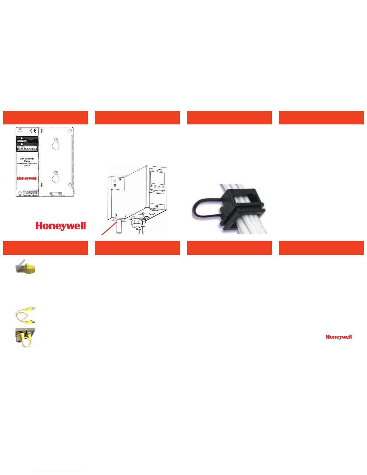
The Midas® LonWorks® interface module is
installed behind the standard Midas® gas
detector as shown in Figure 1. Power and
data connections are supplied directly to the
LonWorks® interface module. All power and
communication to the Midas® unit is provided
via the LonWorks® interface.
Midas® Gas Detector
LonWorks® Interface Module
Figure 1
Figure 2
Customer Wiring
Gently pry the clear locking
tab outside of the yellow jacket
on both ends of the cable as
shown.
Ensure yellow jacket has not moved out of
position when inserting to the Midas® or LON
Module connectors (clear tab is to rest on top of
the yellow jacket bubble).
Caution: Do not over-extend the tab as damage
may result.
Bend the cable into 1½ loops
as shown. The two connectors
should be approximately 3 cm
apart. This is to reduce torque
on the installed connector.
Plug the cable into the Midas
and the Interface as shown.
Loosen the black plastic cable
locker on the bottom of the
Midas. Slide this clamp under
the cable locking tab to
prevent the tab from being
depressed. Tighten the locker.
i)
ii)
iii)
Check the part number and type of sensor
cartridge is correct.
Check the “activate by” date.
Remove sensor cartridge from packaging.
Carefully push the sensor cartridge into
the sensor cartridge chamber until fully
seated.
Lock the sensor cartridge in place using
the tabs on both sides of the sensor
cartridge.
Confirm that the power switch in the
mounting bracket assembly is in the ‘on’
position.
Refit the unit cover by aligning the slots
either side with the locating tabs on the
mounting bracket assembly.
Tighten the thumbscrew located on the
front panel.
Install the supplied RJ-45 cable between
the Midas® and the LonWorks® interface.
i)
ii)
iii)
iv)
v)
vi)
vii)
viii)
ix)
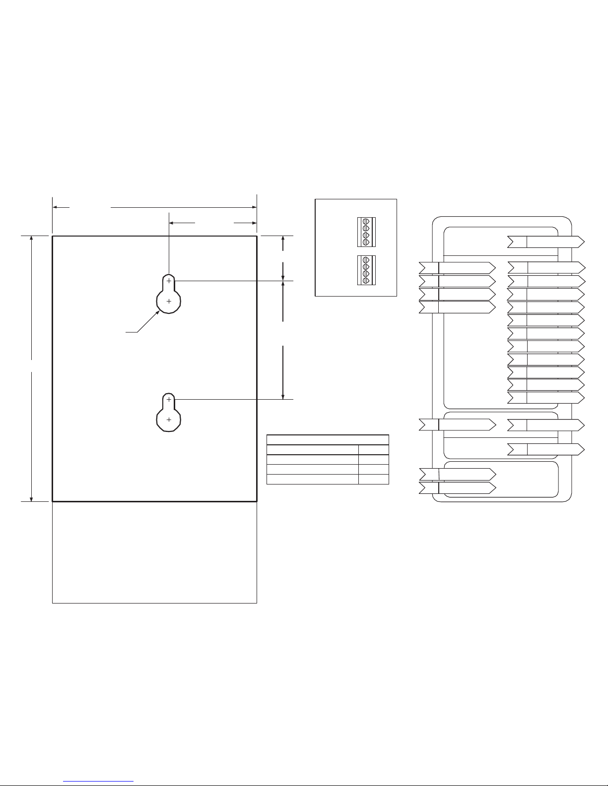
100 mm
(2.54 in.)
130 mm
22.2 mm
58.5 mm
(2.303 in.)
43.5 mm
(1.71 in.)
Ø 12.70 mm
(0.50 in.)
Clearance needed below Midas for tubing and cables.
Mounting Template
LonMark Object Diagram
See Tech Note 1998-0643 for details.
MIDAS LonWorks Device
Open-loop sensor Functional Block
nviReset
SNVT_lev_disc
nvoConc
SNVT_ppm_f
nv1
nvoFaultD
SNVT_lev_disc
nvoFaultS
SNVT_switch
nvoAlm2
SNVT_lev_disc
nvoAlmL
SNVT_lev_disc
nvoAlmThresh1
SNVT_ppm_f
nvoAlmThresh2
SNVT_ppm_f
nvoCellLife
SNVT_elapsed_tm
nviRelay1
SNVT_lev_disc
nviRelay2
SNVT_lev_disc
nviRelay3
SNVT_lev_disc
nvoAlmS
SNVT_switch
nvoGasSelection
SNVT_count
Mandatory
Implementation-Specific
nvoMonState
SNVT_state
nvoNstat
SNVT_state
Virtual Function Block
nciMaxSendT
SNVT_elapsed_tm
cp22
nciMinSendT
SNVT_elapsed_tm
cp24
Node Object Functional Block
nvoStatus
SNVT_obj_status
nv2
nviRequest
SNVT_obj_request
nv1
nvoChkSum
SNVT_count
nv3
Mandatory
Implementation-Specific
Wiring Diagram
Plug 2
Plug 1
Pwr +24 VDC
Lon A
Lon B
Pwr Common
Pwr +24 VDC
Lon A
Lon B
Pwr Common
Wiring Notes:
Maximum wire size is 1.5 mm (16AWG)
Input voltage range is 21.6 to 26.4 VDC.
It is mechanically possible to misalign Plug 1 and Plug 2. Care should be taken when
inserting plug to assure correct alignment.
Plug 1 and Plug 2 are internally connected in parallel to facilitate wiring in bus topology.
LonWorks FT-10 wiring is polarity-insensitive. Lon A and Lon B may be swapped.
Note:
The Midas® LonWorks® interface draws approx 1.7 amps for approx 100 mS after power is applied.
External equipment should be sized appropriately. Additionally, the Midas® requires the supplied power
to rise to the minimum specification (21.6 VDC) within 500mS.
i)
ii)
iii)
iv)
v)
Power Consumption:
Transmitter unit < 5 W
Transmitter with pyrolyzer (std or HTP) < 12.95 W
Transmitter with LonWorks Module < 8 W
Transmitter with LonWorks and pyrolyzer < 15.95 W
 Loading...