

Page 1
Midas Gas Detector
Operating Instructions
• TOC
• General Description
• Product Overview
• Default Configuration
• Installation
• Detector Start-up
• General Operation
• Navigating Menus
• Routine Maintenance
• Pyrolyzer Module Options
• LonWorks® Interface
• Troubleshooting/Faults
• Reflex
• Internal Web Server
• Installation Topologies
• Ordering Information
• Specifications
• Calibration/Bump Testing
• Modbus/TCP Interface
®
• Gas Tables
• Warranty
Page 2

Midas® Gas Detector
Table of Contents
Contents
1 General Description
1 General Description �������������������������������������������������������������������������������������������������������� 1-2
2 Product Overview
2 Product Overview ����������������������������������������������������������������������������������������������������������� 2-2
2�1 Main Chassis ���������������������������������������������������������������������������������������������������������� 2-2
2.1.1 Display ............................................................................................................ 2-2
2.1.2 Pump Module .................................................................................................. 2-3
2.1.3 Sensor Cartridge Chamber ............................................................................. 2-3
2�2 Mounting Bracket Assembly ��������������������������������������������������������������������������������� 2-3
2.2.1 Mounting Bracket ............................................................................................ 2-4
2.2.2 Terminal Module .............................................................................................. 2-4
2�3 Sensor Cartridge ��������������������������������������������������������������������������������������������������� 2-4
2.3.1 Biased Sensor Cartridges ............................................................................... 2-4
2�4 Cover ����������������������������������������������������������������������������������������������������������������������� 2-5
3 Default Configuration
3 Default Configuration ����������������������������������������������������������������������������������������������������� 3-2
4 Installation
4 Installation ����������������������������������������������������������������������������������������������������������������������� 4-2
4�1 Mounting and Location of Detector ��������������������������������������������������������������������� 4-2
4�2 Mechanical Installation ������������������������������������������������������������������������������������������ 4-4
4�3 Sample and Exhaust Tubing Calculations ���������������������������������������������������������� 4-7
4�4 In-line Filters ����������������������������������������������������������������������������������������������������������� 4-8
4�5 Local Detector Option ������������������������������������������������������������������������������������������� 4-8
4�6 Electrical Installation ��������������������������������������������������������������������������������������������� 4-8
4�7 Electrical Connections ���������������������������������������������������������������������������������������� 4-11
4�8 Refitting the Main Chassis ���������������������������������������������������������������������������������� 4-23
4�9 Installing the Sensor Cartridge ��������������������������������������������������������������������������� 4-23
5 Detector Start-Up Procedures
5 Detector Start Up Procedures ��������������������������������������������������������������������������������������� 5-2
Midas Technical Handbook
i
Page 3
Midas® Gas Detector
6 General Operation
6 General Operation ���������������������������������������������������������������������������������������������������������� 6-2
6�1 Normal Operation Mode ���������������������������������������������������������������������������� 6-2
6.1.1 Resetting Alarms, and Faults .......................................................................... 6-4
6�2 Review Mode ����������������������������������������������������������������������������������������������������������������� 6-4
6.2.1 Review Mode Menu Overview ................................................................... 6-4
6�3 Overview of Set-up, Calibration and Test Mode ������������������������������������������������ 6-6
6.3.1 Set-up Menu Overview .............................................................................. 6-6
6.3.2 Calibration Menu Overview ‘ CAL’ ......................................................................... 6-8
6.3.3 Test Menu Overview ‘ tESt’ ........................................................................ 6-9
7 Detailed Procedures for Navigating Mode Submenus
7 Detailed Procedures for
Navigating Mode Submenus ���������������������������������������������������������������������������������������������������7-2
7�1 Review Mode ���������������������������������������������������������������������������������������������������� 7-2
7.1.1 Review Software ‘SW’ ..................................................................................... 7-2
7.1.2 Review Alarms ‘ ALm’ .................................................................................. 7-2
7.1.3 Review Faults ‘ FLt’ ..................................................................................... 7-3
7.1.4 Review Calibration ‘ CAL’ ................................................................................ 7-3
7.1.5 Review Date and Time ‘timE’ ........................................................................... 7-3
7.1.6 Review Detector Address ‘ nEt’ ....................................................................7-3
7.1.7 Review Event Log ‘ Hi St’ .......................................................................... 7-4
7.1.8 Review LCD Backlight Mode ‘LCD’ ................................................................. 7-4
7�2 Set-up, Calibration and Test Modes �������������������������������������������������������������������� 7-4
7.2.1 Set-up Menu ‘ SEt’ ........................................................................................ 7-5
7.2.2 Set Alarms ‘ ALm’ .......................................................................................... 7-5
7.2.3 Set Faults ‘ FLt’ .............................................................................................. 7-6
7.2.4 Set Calibration Interval ‘ CAL’ ......................................................................... 7-7
7.2.5 Set Date and Time ‘timE’ ................................................................................. 7-7
7.2.6 Set Address ‘ nEt’ ........................................................................................ 7-8
7.2.7 Set pass code ‘ PWd’ .................................................................................... 7-8
7.2.8 Set LCD Backlight mode ................................................................................. 7-9
Midas Technical Handbook
ii
Page 4

Midas® Gas Detector
7.2.9 Set Pump control frequency ............................................................................ 7-9
7�3 Calibration Menu ‘ CAL’ ������������������������������������������������������������������������������������ 7-10
7.3.1 Zero Calibration ‘ 0CAL’ ................................................................................. 7-10
7.3.2 Span Calibration ‘ SPAn’ ............................................................................... 7-10
7.3.3 Flow Calibration ‘ FLoW’ ................................................................................ 7-11
7.3.4 mA Calibration ‘mA 4-20’ ............................................................................... 7-12
7�4 Test Menu ‘ tESt’ ��������������������������������������������������������������������������������������������� 7-13
7.4.1 Bump Test ‘ bUmP’ ....................................................................................... 7-13
7.4.2 Alarm/Fault Test ‘ SIm’ ................................................................................ 7-13
7.4.3 Inhibit State ‘ InH’ ....................................................................................... 7-14
7.4.4 Stimulate 4-20mA ‘4-20 mA’ .......................................................................... 7-14
8 Routine Maintenance
8 Routine Maintenance ������������������������������������������������������������������������������������������������������ 8-2
8�1 Sensor Cartridge Replacement ���������������������������������������������������������������������������� 8-3
8.1.1 Sensor Cartridge Fitting/Replacement ............................................................ 8-3
8�2 Pump Replacement ������������������������������������������������������������������������������������������������ 8-4
8�3 Reassembling the Detector ����������������������������������������������������������������������������������� 8-5
8�4 Filter Replacement ������������������������������������������������������������������������������������������������� 8-6
8�5 System Leak Check Procedure ���������������������������������������������������������������������������� 8-7
9 Pyrolyzer Module Options
9 Pyrolyzer Module Options ��������������������������������������������������������������������������������������������� 9-2
9�1 Fitting the Pyrolyzer Module ��������������������������������������������������������������������������������� 9-4
9�2 Reassembling the Detector ����������������������������������������������������������������������������������� 9-6
9�3 Configuring the Detector ��������������������������������������������������������������������������������������� 9-7
9�4 Replacing the Pyrolyzer Heater Block ����������������������������������������������������������������� 9-7
10 Optional LonWorks® Interface Installation
10 Midas LonWorks® Interface Module �������������������������������������������������������������������������� 10-2
10�1 LonWorks® Installation �������������������������������������������������������������������������������������� 10-2
10.1.1 Fitting the LonWorks® Module .................................................................... 10-2
10.1.2 Wiring the Midas® for LonWorks® ............................................................... 10-3
10.1.3 Configuring the Midas® for LonWorks® ...................................................... 10-3
Midas Technical Handbook
iii
Page 5

Midas® Gas Detector
10�2 LonWorks® Software ����������������������������������������������������������������������������������������� 10-4
10.2.1 LonWorks® Overview ................................................................................... 10-4
10.2.2 Network Variable Behaviors ........................................................................ 10-5
10.2.3 Other Characteristics .................................................................................. 10-9
11 Troubleshooting and Fault Diagnosis
11 Troubleshooting and Fault Diagnosis ���������������������������������������������������������������������� 11-2
12 Reflex
12 REFLEX® ��������������������������������������������������������������������������������������������������������������������� 12-2
13 Internal Web Server
13 Internal Web Server ���������������������������������������������������������������������������������������������������� 13-2
14 Typical Installation Topologies
14 Typical Installation Topologies ��������������������������������������������������������������������������������� 14-2
15 Ordering Information
15 Ordering information �������������������������������������������������������������������������������������������������� 15-2
16 Specifications
16 General Specifications ����������������������������������������������������������������������������������������������� 16-2
17 Calibration and Bump Testing
17 Calibration and Bump Testing ����������������������������������������������������������������������������������� 17-2
A Modbus® / TCP Interface
®
13�1 Physical Network Components ������������������������������������������������������������������������ 13-2
13�2 Internet Settings ������������������������������������������������������������������������������������������������� 13-2
13�3 Running the Web Browser �������������������������������������������������������������������������������� 13-4
14�1 Conventional Installation ���������������������������������������������������������������������������������� 14-2
14�2 Modbus/TCP Installation ����������������������������������������������������������������������������������� 14-3
14�3 Power over Ethernet (PoE) Installation ������������������������������������������������������������ 14-3
15�1 Midas® Transmitter �������������������������������������������������������������������������������������������� 15-2
15�2 Midas® Pyrolyzer for NF3 ���������������������������������������������������������������������������������� 15-2
15�3 Midas® High-Temperature Pyrolyzer for Perfluoro Compounds ������������������� 15-2
15�4 Midas® LonWorks® Module ������������������������������������������������������������������������������� 15-2
15�5 Midas® Complete Gas Detector Kits ����������������������������������������������������������������� 15-3
15�6 Accessories and Spares ����������������������������������������������������������������������������������� 15-4
Midas Technical Handbook
iv
Page 6

Midas® Gas Detector
A Modbus/TCP Interface ���������������������������������������������������������������������������������������������������A-2
A�1 Reading Status from the Midas® �������������������������������������������������������������������������A-2
A�2 Sending Commands to the Midas® ���������������������������������������������������������������������A-5
A�3 Determining the MAC Address ����������������������������������������������������������������������������A-6
B Gas Tables
C Warranty Statement
C Warranty Statement �������������������������������������������������������������������������������������������������������C-2
Sensor Cartridge Warranty ����������������������������������������������������������������������������������������C-3
Pyrolyzer Warranty �����������������������������������������������������������������������������������������������������C-3
Midas Technical Handbook
v
Page 7

Midas® Gas Detector
1 General Description
Midas Technical Handbook
1-1
Page 8
Midas® Gas Detector
1 General Description
The Midas® gas detector is an extractive gas sampling system that draws a sample locally or from a remote
point to a sensor cartridge that is located inside the detector’s chassis. A wide range of Asphyxiant, Toxic,
Flammable, Pyrophoric, Corrosive, and Oxidizer (including Oxygen) gas sensor cartridges are available that
enable detection of gases used or generated in the Semiconductor and other industries.
Midas® is wall mounted and displays gas concentration, alarm, fault and status information via its backlit LCD
and LEDs. A simple to use 4-button keypad located under the display provides the facility to set-up, review,
operate and make changes to the detector’s configuration.
Midas® has flexible power and communications capabilities built in as standard. These include 3 on board
relays, 0-21 mA analog output, Modbus/TCP outputs for signal and service connectivity as well as the innovative
Power over Ethernet (PoE) connection that enables a single Ethernet connection to be made for all power,
control and communication requirements. An optional LonWorks® interface is available.
Midas Technical Handbook
1-2
Page 9

Midas® Gas Detector
2 Product Overview
Midas Technical Handbook
2-1
Page 10
Midas® Gas Detector
?
?
?
??
?
?
?
??
?
?
??
? ?
?
?
?
?
?
?
?
??
????
?
???
?
???
?
?
?
?
?
?
?
?
??
?
?
?
??
?
?
?
?
?
??
??
?
?
?
??
?
?
???
???
?
?
??
?
??
?
?
?
?
??
?
?
?
?
?
??
??
??
??
?
?????
??????
?
?
?
??
?
???
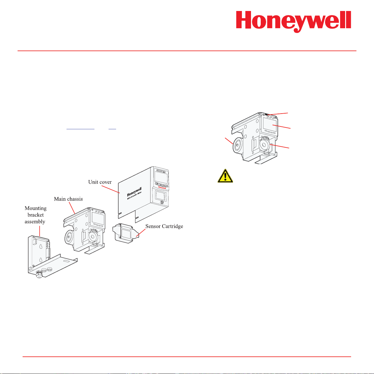
2 Product Overview
The Midas® gas detector comprises of 4 parts: the main
chassis, the mounting bracket assembly, the sensor
cartridge and the unit cover. Diagram 2-1 details the
Midas® general arrangement. Additionally, optional
Pyrolyzer modules for the detection of NF3 or various
PFCs and an optional LonWorks® module are available.
Please refer to Section 9 and 10 respectively for details
of these options.
Diagram 2-1� Midas® general arrangement exploded view
2�1 Main Chassis
The main chassis comprises of the display, pump
assembly, and plug in sensor cartridge chamber.
Diagram 2-2� Main chassis
Service Port
Display
Pump module
Sensor cartridge chamber
Caution
The Service Port is only for use with
approved connectors by Honeywell
Analytics service personnel operating a
system diagnostic� Unauthorized connection
to this port may lead to damage of the
Midas® and external equipment and will not
be covered by the normal product warranty
conditions�
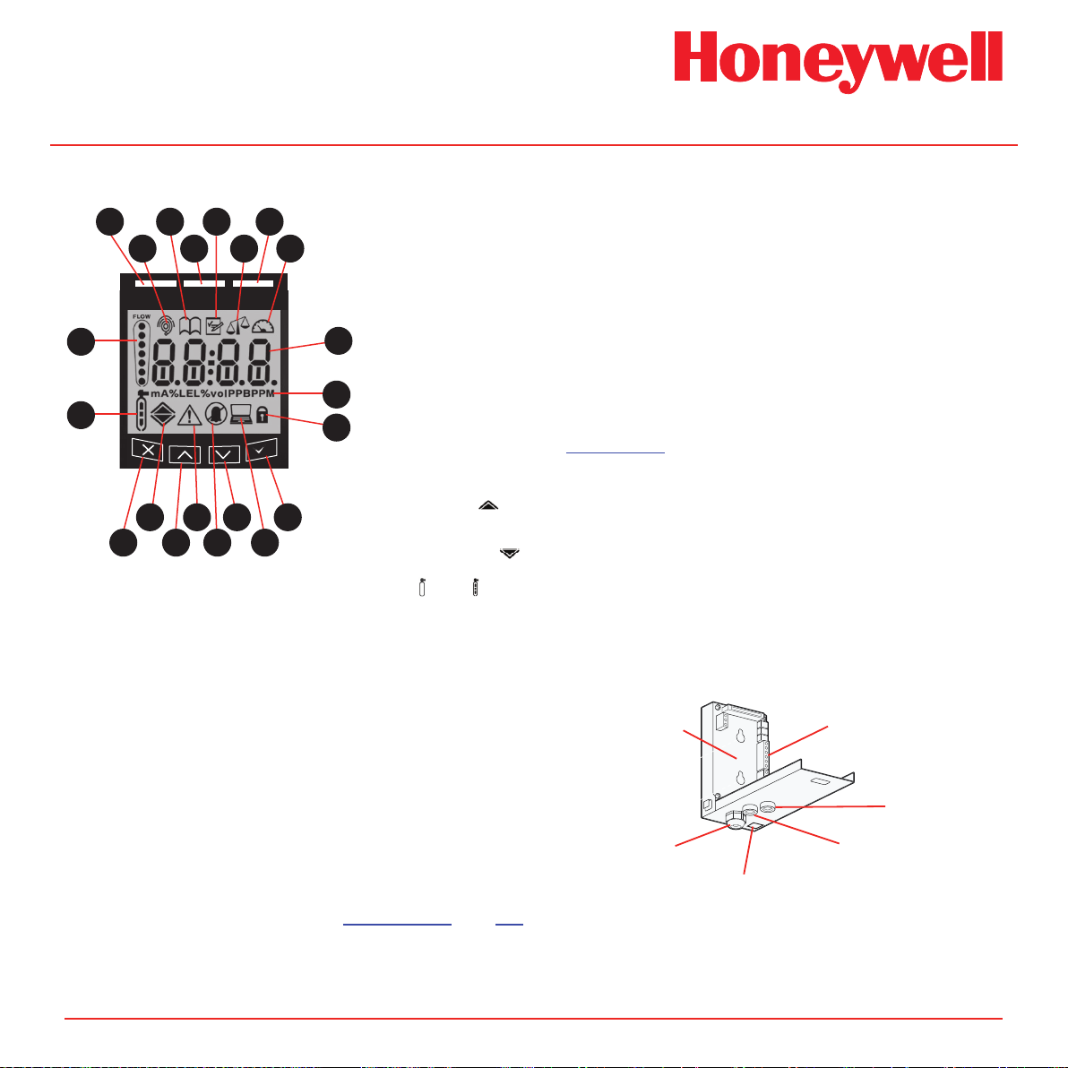
2�1�1 Display
The display is located at the front of the main chassis
and consists of a large alphanumerical and graphical
backlit LCD, 3 LED indicators and a 4-button keypad.
Under normal operation the LCD and LEDs display
gas concentration, alarm and system status. In set-up,
review, calibration and test modes, the LCD shows
the relevant menu options. These menus are simply
navigated using the ‘s’ up, ‘t’ down, ‘3’ accept and
‘X’ cancel buttons.
Midas Technical Handbook
2-2
Page 11
Midas® Gas Detector
Diagram 2-3� Midas® display module layout
1
1
1
1
1
21
1
20
3
1
1
2
4
MDA Scientific Midas
1
1
16
18
1
1
17
19
1
5
7
1
1
6
8
1
1
12
14
1
1
13
15
2�1�2 Pump Module
1. Red alarm LED
2. Normal operation icon
3. Review mode icon
4. Green power LED
5. Set-up mode icon
6. Calibration mode icon
7. Yellow Fault LED
8. Test mode icon
9. Gas concentration and
1
9
1
10
1
11
message display area
10. Displayed units
11. Pass code icon
12. Accept button
13. Network icon
14. Down button
15. Inhibit icon
16. Fault icon
17. Up button
18. Alarm level 1 icon s
Alarm level 2 icon
(For flammable and toxic)
Depletion level 1 icon t
Depletion alarm level 2
19. Cancel button
20. Zero and Span calibration
icons
21. Flow indicator
The pump module is located at the back of the main
chassis. It draws the gas sample from the inlet port
located at the bottom of the mounting bracket assembly
via an inline filter to the sensor cartridge chamber
located at the front of the main chassis. The inline filter
is to protect the elements after the sensor. The sample
goes from the inlet straight to the sensor face, and then
through the rest of the flow system. The sample is then
exhausted via the exhaust port located at the bottom
of the mounting bracket assembly. The pump and
filter assemblies are designed for easy replacement.
For replacement details refer to Sections 8.2 and 8.4
respectively.
2�1�3 Sensor Cartridge Chamber
The sensor cartridge chamber is located at the front of
the main chassis below the display module. The plug
in sensor cartridge is fitted into this area which makes
the electrical connection between the sensor cartridge
and the rest of the electronics as well as providing the
chamber where the sensor cartridge is exposed to the
sampled gas. This connection is lightly lubricated for
ease of sensor replacement. Avoid contact of sensor
cartridge chamber with contaminants (such as dust
and debris). For details of fitting sensor cartridge refer
to Section 4.9.
2�2 Mounting Bracket Assembly
The mounting bracket assembly comprises of the
detector mounting bracket, the terminal module, the
gas sample inlet and outlet ports, the cable/conduit
entry and Ethernet (Modbus/TCP) communications
socket.
Diagram 2-4� Mounting bracket assembly
Mounting bracket
Cable entry
Ethernet/PoE socket
Terminal module
Gas inlet port
Gas outlet port
Midas Technical Handbook
2-3
Page 12
Midas® Gas Detector
REMOVE
AT TIME OF
INSTALLATION
2�2�1 Mounting Bracket
The metal mounting bracket has two slots that allow
the detector to be easily mounted to a wall using two
suitable screws (DIN rail or horizontal mounting options
are also available). For further details of mounting the
detector refer to Section 4.
2�2�2 Terminal Module
The terminal module is located on the mounting
bracket. All electrical connections to Midas® are made
via this module. Wire entry to the terminal module area
is via the PG16 cable entry/conduit entry located at
the bottom of the mounting bracket assembly.
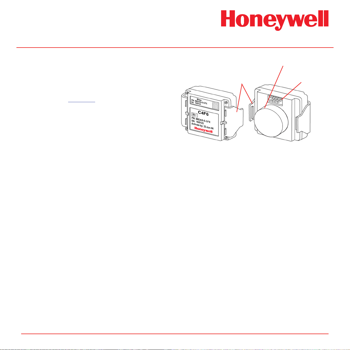
2�3 Sensor Cartridge
A wide range of Flammable, Pyrophoric, Corrosive,
and Oxidizer (including Oxygen) sensor cartridges can
be fitted to Midas®. The plug in sensor cartridges are
fitted in the sensor cartridge chamber at the front of the
main chassis. To access the chamber the unit cover is
removed by unscrewing the thumbscrew located at the
front of the detector. The pre-calibrated smart sensor
cartridges can easily be fitted or replaced as they
simply plug into the detector without the need for any
tools. The sensor cartridge is firmly held in place by
two locking tabs. Some cartridges are shipped with a
protective cap to shield them from contaminants during
shipping. This cap must be removed before inserting
the cartridge into the Midas® unit, failure to do so may
damage the Midas® transmitter.
Diagram 2-5� Sensor cartridge
Locking tabs
Front Back
Protective Cap
(remove before use)
Connector
2�3�1 Biased Sensor Cartridges
Some sensor cartridges are shipped with a battery
powered electrical supply in order to keep the cell
effectively ‘warmed up’ and ready to monitor once
installed in the Midas® unit. Battery powered bias
circuits are supplied for TEOS, NO, and CO2. The bias
circuit is removed just before insertion into the Midas®
system and the sensor cartridge is thus ready sooner
for effective gas detection.
Should a bias voltage not be applied (e.g. during
a power failure), the cell will take a longer time to
recover before effective gas detection can take place.
The longer the loss of applied power, the longer the
recovery time. During this recovery time, there is a
chance for false/inaccurate readings. Refer to the
relevant sensor cartridge data sheet for information
on each sensor cartridge.
Midas Technical Handbook
In order to avoid the risk of loss of gas detection due
to unforeseen power loss, we recommend that a power
management solution such as uninterruptible power
supplies are used.
2-4
Page 13
Midas® Gas Detector
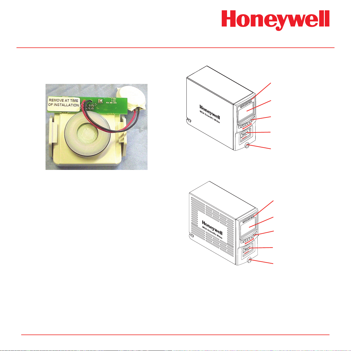
Sensor Cartridge
Note
Sensor warranty is void if the sensor cartridge
is opened by unauthorized user.
Diagram 2-6� Biased Sensor�
2�4 Cover
The standard cover provides environmental protection
and fits over the top, front and sides of the main
chassis. The front panel has viewing windows for the
LCD, LEDs and sensor cartridge fitted in the sensor
cartridge chamber. Underneath the LCD window are
the 4 push buttons used for navigating the detector’s
software menus. The cover is easily removed to allow
access to the chassis by unscrewing the thumbscrew
on the front panel and pulling the cover forwards off
the main chassis.
Midas units fitted with a pyrolyzer utilize a ventilated
cover due to the high temperatures generated by the
pyrolyzer unit (See Diagram 2-7)
Diagram 2-7� Midas® covers
LED Windows
LCD Window
Pushbuttons
Sensor Cartridge
viewing window
Thumbscrew
Standard Cover
LED Windows
LCD Window
Pushbuttons
viewing window
Thumbscrew
Ventilated Pyrolyzer Cover
Midas Technical Handbook
2-5
Page 14

Midas® Gas Detector
3 Default Conguration
Midas Technical Handbook
3-1
Page 15

3 Default Conguration
As standard, the Midas® gas detector is factory configured as below:
Table 3-1� Midas® default conguration
1.0 mA Fault
Current source with:
2.0 mA Inhibit
3.0 mA Maintenance Fault
4.0 to 20.0 mA Gas reading (normal operation)
21.0 mA Over range
Toxic Gas Flammable Gas Oxygen
Midas® Gas Detector
Full Scale (FS)
Lowest Alarm Level (LAL)
Lower Detectable Limit
(LDL)
Alarm 1
(Relay 1)
Alarm 2
(Relay 2)
Fault
(Relay 3)
Latching
Pass code
IP Address
®
1
Midas
detectors are not ETL approved for monitoring in or sampling from classied areas above 25% LEL
Typically 4 x Threshold Limit
Value (TLV)
Typically 1/2 TLV 10% LEL 5% v/v
Typically 0.4 TLV 9% LEL 0% v/v
The LDL is the minimum level that is reliably distinguishable from zero.
1/2 TLV 10% LEL 23.5% v/v (Rising)
Contact Normally Open (NO), closes on alarm.
TLV 20% LEL 19.5% v/v (Falling)
Contact Normally Open (NO), closes on alarm.
Contact Normally Open (NO). Instrument Fault Only
Latching. Alarm and fault relays DO NOT automatically reset when reading falls below alarm
thresholds. Relays MUST be manually reset.
169.254.60.47 subnet mask 255.255.255.0
100% Lower Explosive Limit
Normally de-energized, energizes on alarm.
Normally de-energized, energizes on alarm.
Normally energized, de-energizes on fault.
No pass code set.
(LEL)
1
25% Volume (v/v)
See Table 7-3 for more information on Relay Configuration
Midas Technical Handbook
3-2
Page 16

Midas® Gas Detector
4 Installation
Midas Technical Handbook
4-1
Page 17
Midas® Gas Detector
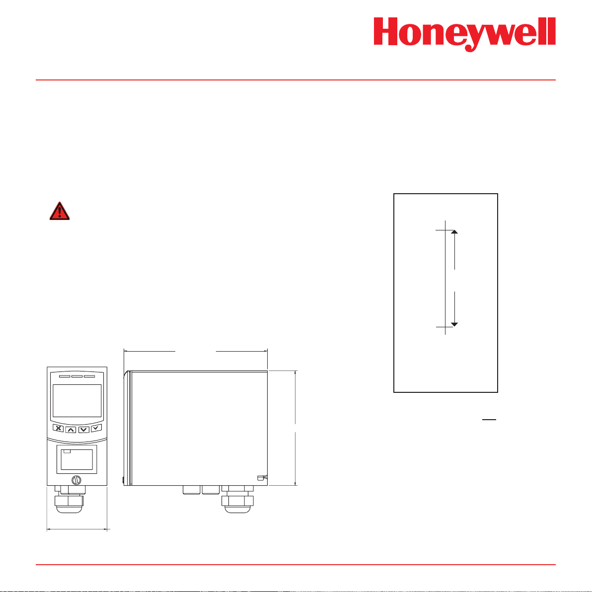
4 Installation
For ease of installation Midas® has been designed
to allow the installation of the mounting bracket
assembly and terminal module separately from the
other parts of the detector. The detector location and
hard wiring can therefore be completed before tting
the detector’s main chassis and sensor cartridge.
WARNING
Midas® is designed for installation and use in
indoor safe area non-explosive atmospheres�
Installation must be in accordance with the
recognized standards of the appropriate
authority in the country concerned� Prior
to carrying out any installation ensure local
regulations and site procedures are followed�
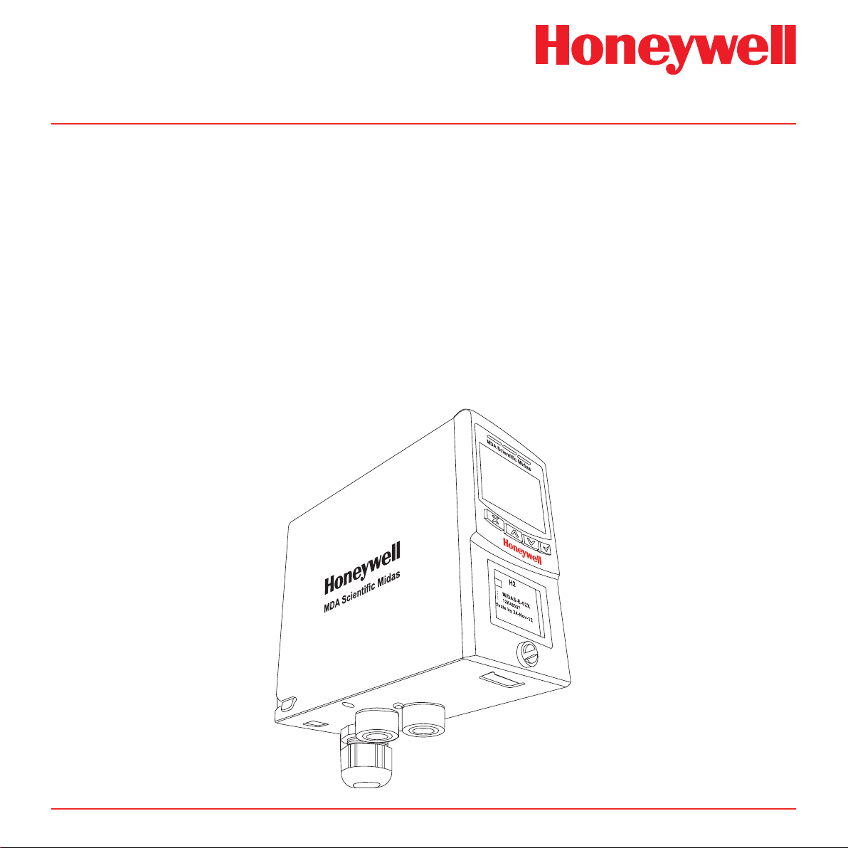
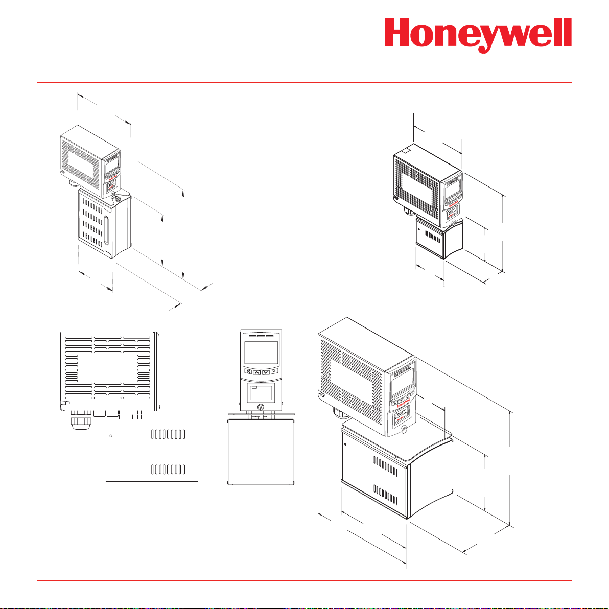
Diagram 4-1. Midas® outline dimensions
5.91 in [150.00mm]
MDA Scientific Midas
4�1 Mounting and Location of Detector
The Midas® gas detector has an integral mounting
bracket assembly that is easily mounted to a
suitable vertical surface such as a wall, tool housing,
mounting plate on a pole etc.
Drill Template
Drill 2 x
M4 holes
2�3 in
(58�50mm)
honeywell
PN: MIDAS-E-CDX
SN: 12K-48397
Activate by 24-Nov-12
honeywell
2.48 in [63.00]
Midas Technical Handbook
z
zellweger analytics
GAS DETECTOR
4.72 in [120.00mm]
4-2
Note
This drill template is not to scale.
The Midas Quick Start Guide
(MIDAS-A-020) contains a full
scale drawing.
Ensure all measurements are
correct before using as an actual
drill template.
Use 2 x M4 Screws or equivalent
for mounting (head size 6-12
mm (1/4” - 1/2”))
Page 18
Midas® Gas Detector
Note: Heat shield not present on all pyrolyzers.
3.9 in.
(98 mm)
3.9 in.
(205 mm)
Midas-A-039
9.6 in.
(244 mm)
5.2 in.
(132 mm)
2.4 in.
(60 mm)
Midas® Transmitters and Pyrolyzers
Midas-T-OOP
MDA Scientific Midas
honeywell
PN: MIDAS-E-CDX
SN: 12K-48397
Activate by 24-Nov-12
honeywell
6.0 in
(152 mm)
3.2 in
(83 mm)
2.3 in.
(59 mm)
7.9 in
(201 mm)
3.2 in
(81 mm)
2.5 in
(62 mm)
Midas-T-HTP
Midas Technical Handbook
4-3
8.2 in.
(209 mm)
9.1 in.
(233 mm)
4.4 in.
(113 mm)
5.5 in.
(140 mm)
4.0 in.
(101 mm)
Page 19

Midas® Gas Detector
Below are some considerations when installing the
Midas® Gas Detector:
1. Mount the detector on a surface that is flat,
firm and suitable for its size and weight.
2. Use the drill template supplied to drill the holes
for the fixings.
3. Use fasteners appropriate for the surface
being mounted to.
4. Ensure the head size of fastener used will not
snag the terminal PCB 6-12 mm (.25 in - .5 in).
5. Consider the conduit/cable weight and its
stress on the installation.
6. Position the detector so that it can be easily
accessed.
7. Position the detector so that it is at a suitable
height (normally eye level) for the display to
be clearly seen.
8. Take into consideration the space required
to remove the detector’s cover and locking/
unlocking the sensor cartridge locking clips.
Minimum recommended spacing between
multiple Midas® units is 82 mm (3.23 in).
9. Take into consideration the space required for
sample inlet and exhaust tubing (for remote
monitoring), and for the inlet filter (for local
monitoring).
10. Take into consideration the space required for
cable or conduit access.
4�2 Mechanical Installation
The following steps and diagrams show how to separate
the mounting bracket assembly from the main chassis
and mount it on a vertical flat surface.
1. Unscrew the thumbscrew located on the front
panel.
2. Remove the cover by pulling it forwards off the
main chassis. Be sure to remove the internal
packing card securing the pump. Failure to
remove this packing will result in damage to
the Midas® unit. (See Diagram 4-2)
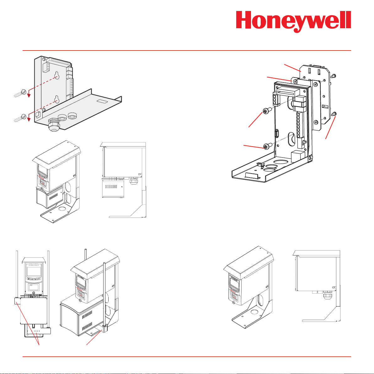
3. Unscrew the two retaining screws located at
the bottom front of the chassis.
4. Holding the mounting bracket assembly with
one hand use the other to carefully pull the
main chassis forward to disconnect it from the
mounting bracket assembly.
5. Using the drill template provided drill two holes
58.50 mm vertically apart for 2 x round head M4
fixing screws.
6. Partially screw the fixings into the mounting
surface.
7. Place the mounting bracket assembly over
the screws so they pass through the mounting
holes and then slide down to locate in the slots.
8. Tighten the screws to secure the mounting
bracket assembly.
Midas Technical Handbook
4-4
Page 20
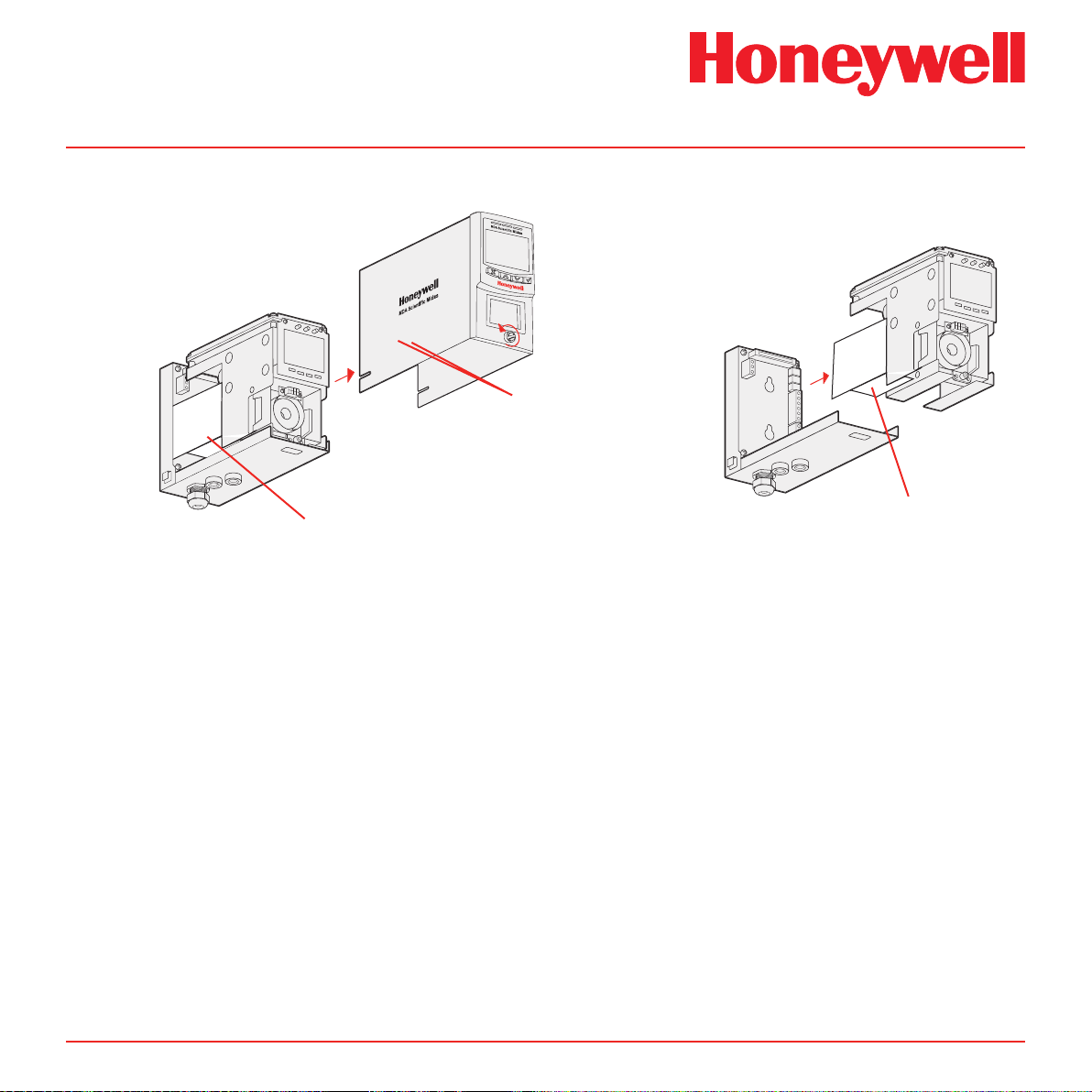
Removing cover
Midas® Gas Detector
Diagram 4-2� Mechanical installation
chassis
Removing chassis
mounting
bracket
chassis
TICE !
IMPORTANT NO
ve internal
ore
Remo
shipping protection from
the pump module brf
installation
Internal packing card
Remove before use.
loosen
cover
Chassis Mounting Screws
mounting
bracket
IMPORTANT NOTICE !
Remove internal
shipping protection from
the pump module brfore
installation
Internal packing card
Remove before use.
Midas Technical Handbook
4-5
Page 21
Midas® Gas Detector
screws
Optional Midas
Diagram 4-3. Mechanical installation
mounting bracket
Standard Midas® Wall Mount
®
Pyrolyzer Adjustable “L” Bracket Mount
(MIDAS-A-032)
DIN Rail Bracket
Spacer Bracket
2x M4 Screws
Secures Midas
Spacer Bracket
®
to
Optional Midas® DIN Rail
Mount (MIDAS-A-036)
4x M3 Screws
Secures DIN Rail
to Spacer Bracket
MDA Scientific Midas
honeywell
PN: MIDAS-E-CDX
SN: 12K-48397
Activate by 24-Nov-12
honeywell
Top Access Tubing Connector
(MIDAS-A-031)
Midas Technical Handbook
Note:
When using the Adjustable
“L” bracket with the HighTemperature Pyrolyzer
unit, (2) Top Access Tubing
Connectors (MIDAS-A-
031) must be used to insure
proper operation.
Optional Midas® Adjustable “L” Bracket Mount
(MIDAS-A-032)
4-6
Page 22

Midas® Gas Detector
4�3 Sample and Exhaust Tubing Calculations
The following tables show the flow rate, tubing
length, transport time, and maximum pressure and
vacuum at the inlet and exhaust points. Tubing
lengths vary among gases. See Appendix B for
recommended lengths.
Table 4-1. Inlet sample specications
Inlet Sample Specifications:
Maximum
Tubing Length, m (ft)
Transport Time (sec), ID 1/8”
Transport Time (sec), ID 3/16”
Sample Point Vacuum
(Negative pressure)
Flow rate, cc/min.
Tubing OD, mm (in)
Tubing ID, mm (in)
1
Honeywell Analytics recommends the thick-wall tubing (1/8”
ID) for best speed of response.
2
The ow rate is electronically maintained at approximately
500 cc/min and may vary within acceptable tolerances.
Table 4-2. Outlet sample specications
Outlet Sample Specifications:
Tubing Length, m (ft)
Back Pressure
at Exhaust Point
(Excluding tubing)
Tubing OD, mm (in)
Tubing ID, mm (in)
30 (100) 20 (66) 10 (33) 0
1
28 19 10 1
63 43 23 1
-25.4 cm H2O (-10 in H2O) Maximum
500 (Flow is constant)
6.35 (0.25)
3.18 (0.125)
Maximum
30 (100)
20.3 cm H2O (8 in H2O) Maximum
6.35 (0.25)
4.76 (0.188)
2
Note
Honeywell Analytics recommends the use of
Teon FEP (Fluorinated Ethylene Polymer)
tubing to assure proper sample transport.
The properties of Teon FEP make it the
best choice for transporting sample toxic
gases to instruments when compared with the
properties of other similar tubing materials.
If the pressure/vacuum on the inlet/exhaust lines
does not meet the recommended values in Tables
4-1 and 4-2, the following chart describes potential
fault conditions that may be brought on by the
external inuences thus resulting in an F81 Flow
Fault.
External Flow Fluctuation Fault 81 Explanation
Low
1
(0-150 cc/min)
Low
2
(0-150 cc/min)
Medium
3
(~200-450 cc/min)
High
4
(> 600 cc/min)
None No Midas® will auto-adjust
Midas® changes the flow
Ye s
(up to 100 cc/min
flow swings)
Yes and No Ye s
Yes and No Ye s
gradually. If external flow
changes are large and rapid,
Likely
the final reading will be different
from what Midas® expected.
Midas® will issue Fault 81.
Minimum flow rate for the
pump is ~300 cc/min. With this
external flow, the auto-adjust
cannot work because the pump
cannot produce a flow at this low
level. The problem is worse if
there are flow fluctuations.
Midas® cannot reduce the
external flow. Midas® will issue
Fault 81 due to high flow
Midas Technical Handbook
4-7
Page 23
Midas® Gas Detector
4�4 In-line Filters
External filters must be used to protect the
tubing from contamination. Use particulate
lter part number 780248 for normal gases and
1830-0055 or 1991-0147 for corrosive gases.
Replace the filter every 3 months. Refer to
Appendix B for specic gases.
4�5 Local Detector Option
The Midas® gas detector can also be used to
monitor for gas at the location of the detector. To
do this an inline lter is simply connected to the
sensor cartridge gas inlet port. The external dust
lter part number is 780248 for normal gases and
1830-0055 or 1991-0147 for corrosive gases. The
area around the detector is then being monitored
as opposed to a sample being drawn from a remote
location.
Diagram 4-4� Local gas detector option
MDA Scientific Midas
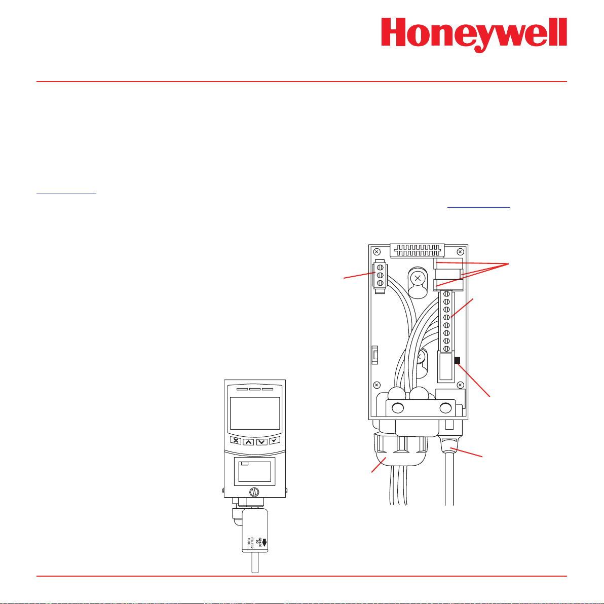
4�6 Electrical Installation
Access for the electrical wires to the terminal module
is made via the PG16 cable gland located at the
bottom of the mounting bracket assembly. The
cable gland can be removed and replaced with a
suitable conduit fitting if required. The wire routing of
a typical installation is shown in the diagram below,
wiring details are shown in Diagram 4-6.
Diagram 4-5� Typical wire routing
4-20mA
Analog
Output
Terminals
Relay Contact
Terminals
Relay NO/NC
Jumpers
Power Switch
MIDAS-T-001 transmitter
installed with in line particulate
lter for local ambient monitoring
mode
Midas Technical Handbook
honeywell
PN: MIDAS-E-CDX
SN: 12K-48397
Activate by 24-Nov-12
honeywell
Ethernet Cable
Cable Gland
The terminals used are suitable for conductors of 24
to 14 AWG (0.5 to 1.8mm Dia.). The use of 16 AWG
(1.5 mm Dia.) conductors is recommended.
4-8
Page 24

If Power over Ethernet (PoE) is used to power
the device, then 24 VDC power must not also be
connected to the device, (or conversely if 24 VDC
is used to power the Midas®, then electrical power
via the Ethernet port must not be applied). Failure
to observe this requirement may cause damage to
the gas detection system and will not be covered
by the standard warranty.
When connecting the wires ensure that the power
switch is in the off position.
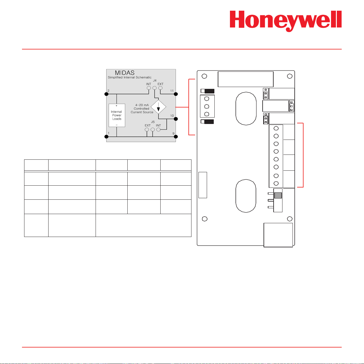
Diagram 4-5 shows the terminal module layout
and terminal identication as well as the jumper
locations.
Note: Earthing Requirements
If the Midas® unit’s metal chassis is not
connected directly to a metal surface for
earthing purposes, an additional earth wire
will be required. Connect a wire via the
PG16 gland to the dedicated earth tag (screw
terminal) located on the bottom bracket
and connect the other end of the wire to a
dedicated external earthing point.
Midas® Gas Detector
If Power over Ethernet (PoE) power supply
is being used, shielded CAT5 Ethernet cable
is recommended.
Please ensure that your wiring avoids earth
ground loops that may affect the performance
of your equipment
Midas Technical Handbook
4-9
Page 25
Midas® Gas Detector
RJ-45
8
7
2
3
4
5
6
1
DC
PWR
+24 V
COM
NO
NC
Relay3
Relay2
Relay1
ON
SW
OFF
11
10
9
Analog Current
Loop 4-20 mA
INT EXT
EXT INT
-supply
J5
J4
+supply
J1
NO
NC
J2
NO
NC
J3
PYROLYZER
CONNECTOR
Relay1
}
Relay2
}
Relay3
}
Diagram 4-6� Midas® terminal layout and identication
See Relay
function
table below
Display Description Relay 1 Relay 2 Relay 3
Note
1FLt
2Flt
CmbF
nEtr
Instrument Fault
Only
Separate Fault
Relays
Combined Fault
Relay
Remote control of
relays via Modbus/
TCP or LonWorks
The 3 relays onboard the Midas® unit can be controlled remotely from a separate controller system using
Modbus/TCP commands (or via LonWorks® if the optional interface is used). In this remote mode, the relays
cannot be controlled by the Midas® itself and only by the remote controller device (PLC, SCADA, etc.)
Alarm 1 Alarm 2
Any Alarm
Maintenance
Fault
Alarm 1 Alarm 2 Any Fault
Relays respond to Modbus or
LonWorks® holding registers only.
®
Instrument
Fault
Instrument
Fault
Relays
are user
congurable
Midas Technical Handbook
4-10
Page 26
Midas® Gas Detector
4-20 mA
Controlled
Current Source
Internal
Power
Loads
J4
INT EXT
J5
EXT INT
11
10
9
MIDAS
Simplified Internal Schematic
2
1
-
+
+
-
24 VDC
+
-
24 VDC
R
Load
4-20 mA
Controlled
Current Source
Internal
Power
Loads
J4
INT EXT
J5
EXT INT
11
10
9
MIDAS
Simplified Internal Schematic
2
1
-
+
+
-
24 VDC
R
Load
4-20 mA
Controlled
Current Source
Internal
Power
Loads
J4
INT EXT
J5
EXT INT
11
10
9
MIDAS
Simplified Internal Schematic
2
1
-
+
+
-
24 VDC
R
Load
4-20 mA
Controlled
Current Source
Internal
Power
Loads
J4
INT EXT
J5
EXT INT
11
10
9
MIDAS
Simplified Internal Schematic
2
1
-
+
+
-
Ethernet
+
-
24 VDC
R
Load
RJ-45 Connector
48 VDC
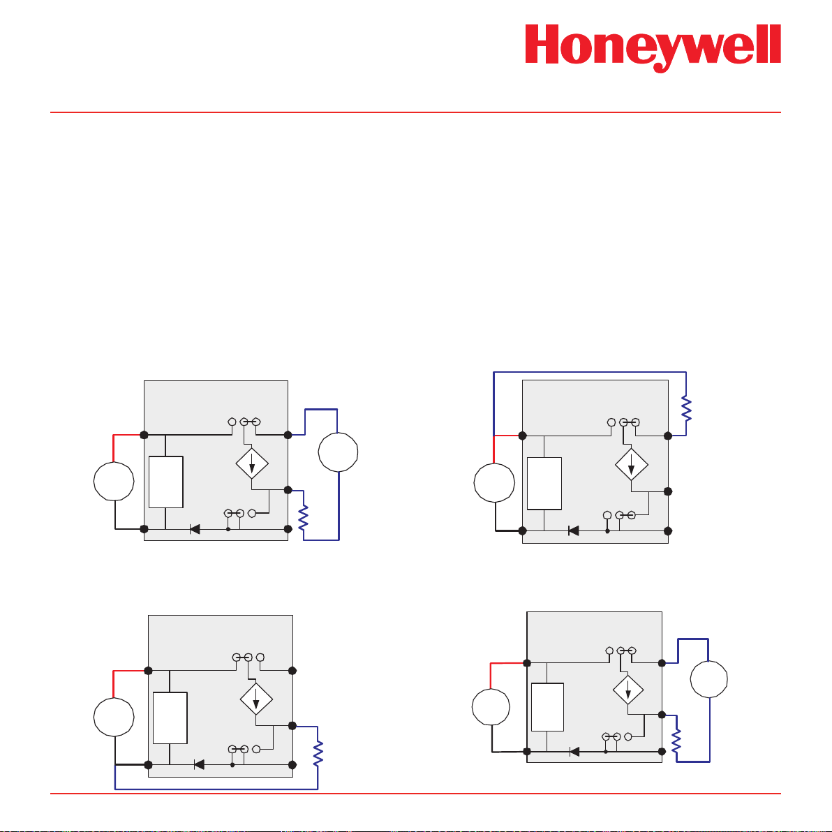
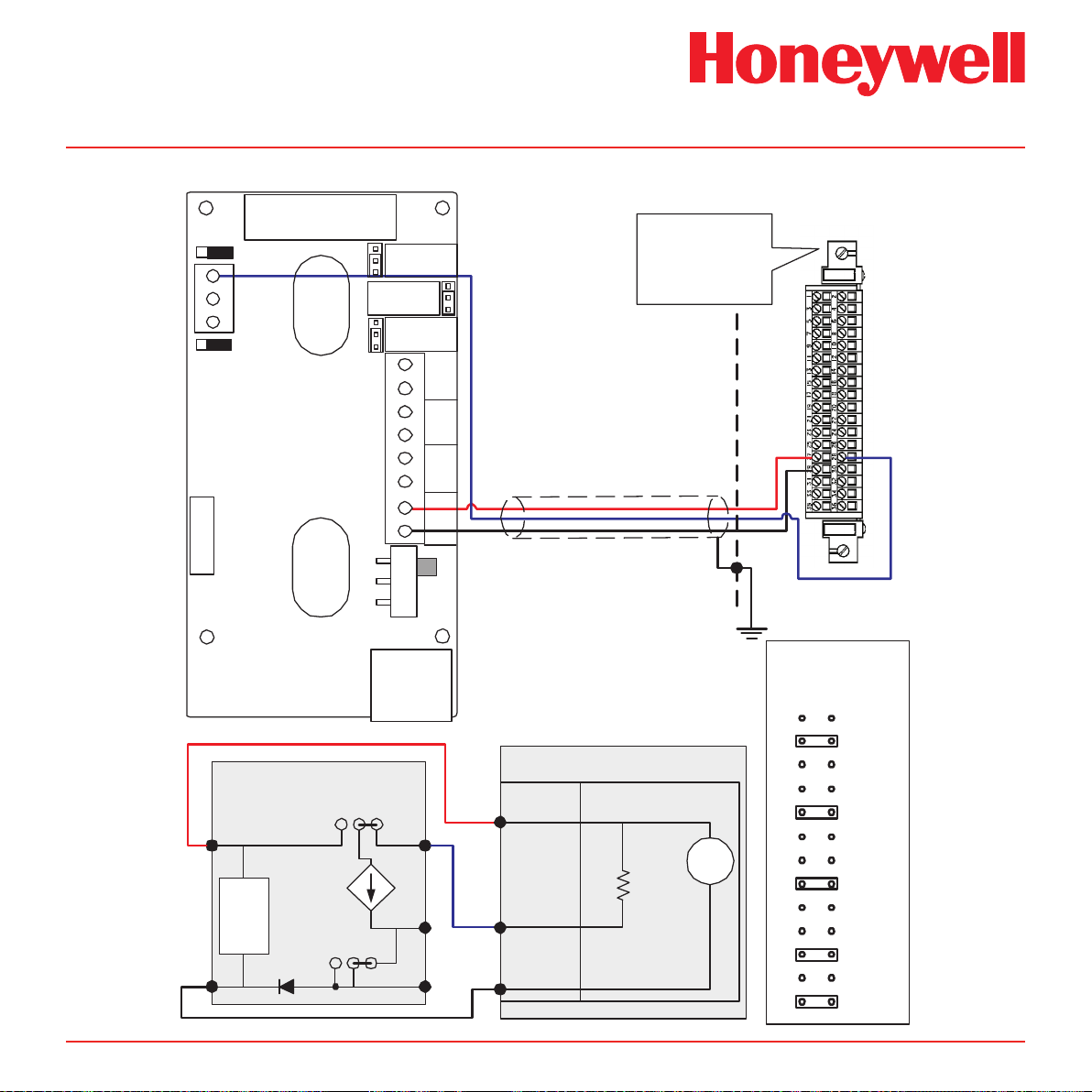
4�7 Electrical Connections
Midas® can be powered by either 24 VDC via
traditional discrete wiring or by approximately 48
VDC delivered through the Ethernet cable from
a PoE source. In either case the 4-20 mA analog
output can be used. This can be congured for
fully isolated operation. With 24 VDC power the
4-20 mA output can be congured for sink, source
or isolated output operations.. Below are some
schematic diagrams of typical electrical connection
Diagram 4-7� Generic Example
Midas® 4-Wire Isolated Output
configurations. Specific wiring instructions for
connecting a Midas to a Honeywell Analytics Sieger
System-57TM are provided on pages 4-12 to 4-16.
Specic instructions for connection to a Honeywell
Analytics TouchPointTM are provided on pages 4-17
to 4-20 and the HA71 on pages 4-21 and 4-22.
Note:
When wiring the Midas Transmitter to a
controller, program the controller for a 1-2
second delay before reporting to prevent
false alarms.
Diagram 4-9� Generic Example
Midas® 3-Wire Sinking Output
Diagram 4-8� Generic Example
Midas® 3-Wire Sourcing
Midas Technical Handbook
Diagram 4-10� Generic Example
Midas® Isolated 4-20 mA Output w/PoE Power
4-11
Page 27
Midas® Gas Detector
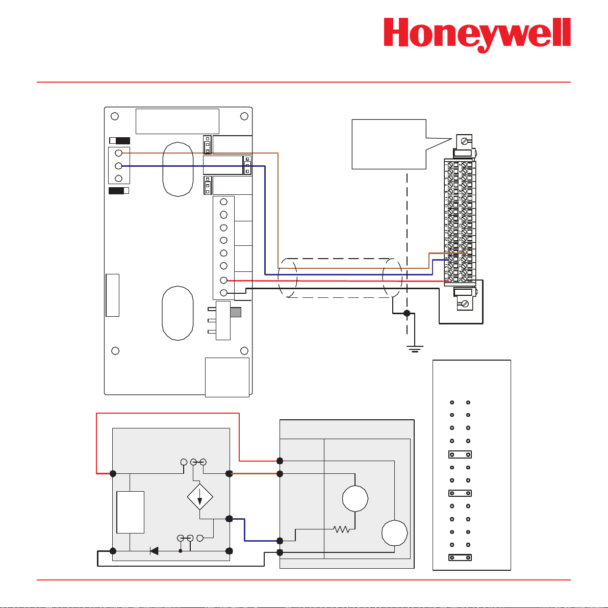
Diagram 4-11� Midas® to 5701 4-Wire Isolated Connection
J4
+supply
INT EXT
11
10
9
Loop 4-20 mA
Analog Current
EXT INT
-supply
J5
PYROLYZER
CONNECTOR
MIDAS
Simplified Internal Schematic
2
+
Internal
Power
Loads
-
1
INT EXT
4-20 mA
Controlled
Current Source
EXT INT
Sieger System 57
Relay/Field Interface Card
NC
J1
NO
NC
J2
NO
NC
J3
NO
+24 V
COM
Relay1
Relay2
Relay3
8
}
7
6
5
4
3
2
1
Relay1
}
Relay2
}
Relay3
DC
PWR
ON
SW
OFF
Shielded Cable
05701-A-0326
05701-A-0327
05701-A-0328
05701-A-0329
05701-A-0330
Cabinet
29
35
28
36
5701 Card
RJ-45
Sensor Drive Module
Link Positions
LK13
LK12
System 57
J4
11
10
J5
9
35
28
29
36
Relay/Field
Interface Card
5701 Control Card
VDC
Sense
Resistor
Isolated Loop
Supply
~40 mA max
+
24
Transmitter
Supply
VDC
+
24
-
LK11
LK10
LK9
LK8
LK7
LK6
LK5
LK4
LK3
LK2
LK1
Midas Technical Handbook
4-12
Page 28
Midas® Gas Detector
4-20 mA
Controlled
Current Source
Internal
Power
Loads
J4
INT EXT
J5
EXT INT
11
10
9
MIDAS
Simplified Internal Schematic
2
1
-
+
Sieger System 57
Relay/Field Interface Card
05701-A-0326
05701-A-0327
05701-A-0328
05701-A-0329
05701-A-0330
System 57
Relay/Field
Interface Card
5701 Control Card
+
24
VDC
-
27
29
28
Sense
Resistor
~170 Ohm
Cabinet
29
2827
Shielded Cable
Transmitter
Supply
5701 Card
Sensor Drive Module
Link Positions
LK12
LK5
LK6
LK7
LK8
LK9
LK10
LK11
LK1
LK2
LK3
LK4
LK13
RJ-45
8
7
2
3
4
5
6
1
DC
PWR
+24 V
COM
NO
NC
Relay3
Relay2
Relay1
ON
SW
OFF
11
10
9
Analog Current
Loop 4-20 mA
INT EXT
EXT INT
-supply
J5
J4
+supply
J1
NO
NC
J2
NO
NC
J3
PYROLYZER
CONNECTOR
Relay1
}
Relay2
}
Relay3
}
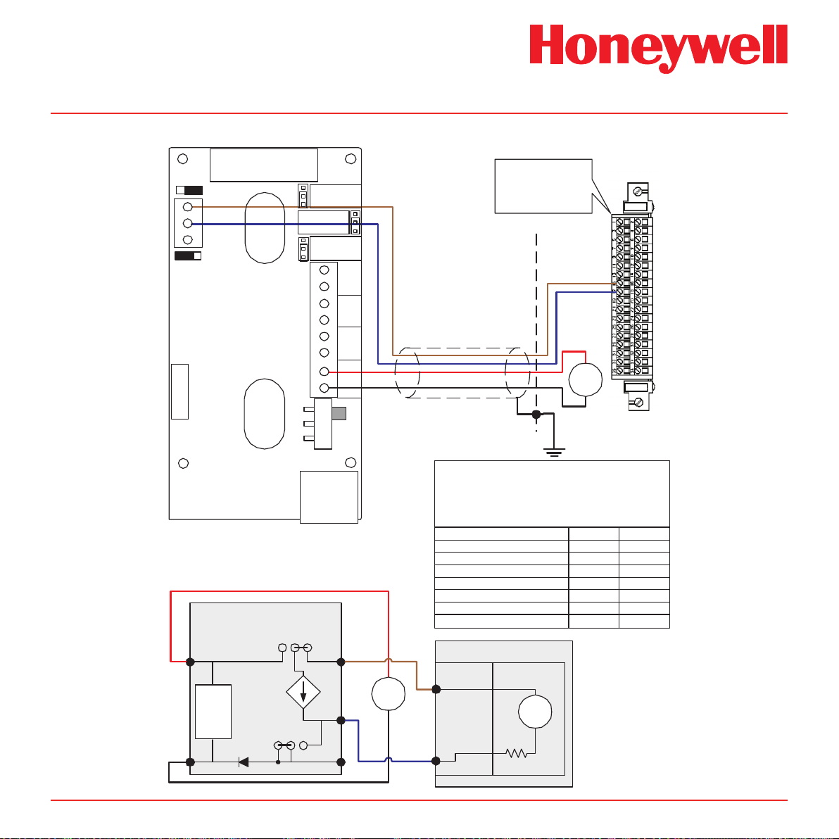
Diagram 4-12� Midas® to 5701 3-Wire Sourcing Connection
Midas Technical Handbook
4-13
Page 29
Midas® Gas Detector
4-20 mA
Controlled
Current Source
Internal
Power
Loads
J4
INT EXT
J5
EXT INT
11
10
9
MIDAS
Simplified Internal Schematic
2
1
-
+
Sieger System 57
Relay/Field Interface Card
05701-A-0326
05701-A-0327
05701-A-0328
05701-A-0329
05701-A-0330
System 57
Relay/Field
Interface Card
5701 Control Card
+
24
VDC
-
27
29
28
Sense
Resistor
~170 ohm
Cabinet
29
28
27
Shielded Cable
Transmitter
Supply
5701 Card
Sensor Drive Module
Link Positions
LK12
LK5
LK6
LK7
LK8
LK9
LK10
LK11
LK1
LK2
LK3
LK4
LK13
RJ-45
8
7
2
3
4
5
6
1
DC
PWR
+24 V
COM
NO
NC
Relay3
Relay2
Relay1
ON
SW
OFF
11
10
9
Analog Current
Loop 4-20 mA
INT EXT
EXT INT
-supply
J5
J4
+supply
J1
NO
NC
J2
NO
NC
J3
PYROLYZER
CONNECTOR
Relay1
}
Relay2
}
Relay3
}
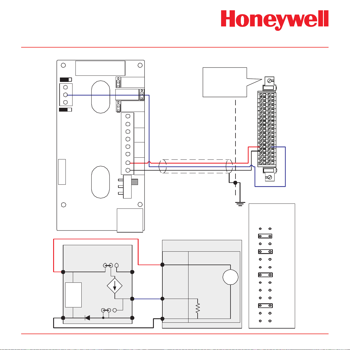
Diagram 4-13� Midas® to 5701 3-Wire Sinking Connection
Midas Technical Handbook
4-14
Page 30
4-20 mA
Controlled
Current Source
Internal
Power
Loads
J4
INT EXT
J5
EXT INT
11
10
9
MIDAS
Simplified Internal Schematic
2
1
-
+
Sieger System 57
Quad Relay Interface Card
05704-A-0121
with
4 Channel Control Card
05704-A-0145
Cabinet
(01) 17
(S) 15
36
Shielded Cable
RJ-45
8
7
2
3
4
5
6
1
DC
PWR
+24 V
COM
NO
NC
Relay3
Relay2
Relay1
ON
SW
OFF
11
10
9
Analog Current
Loop 4-20 mA
INT EXT
EXT INT
-supply
J5
J4
+supply
J1
NO
NC
J2
NO
NC
J3
PYROLYZER
CONNECTOR
Relay1
}
Relay2
}
Relay3
}
+
24
VDC
-
+
24
VDC
-
Note:
The above schematic shows the MIDAS connected
to channel 1 on the 5704 card. The terminal numbers
for all four channels are as follows:
MIDAS Function Loop + Loop Midas Ter minal Number
Color in this figure
5704 Channel 1 Terminal
5704 Channel 4 Terminal
5704 Channel 3 Terminal
5704 Channel 2 Terminal
11
Brown
15
22
21
16
System 57 Function S
10
Blue
17
24
23
18
01
17
15
System 57
Relay/Field
Interface Card
5704 Control Card
+
24
VDC
-
Sense
Resistor
Loop
Supply
Not optically isolated
Diagram 4-14� Midas® to 5704 4-Wire Connection
Midas® Gas Detector
Midas Technical Handbook
4-15
Page 31

Midas® Gas Detector
4-20 mA
Controlled
Current Source
Internal
Power
Loads
J4
INT EXT
J5
EXT INT
11
10
9
MIDAS
Simplified Internal Schematic
2
1
-
+
System 57
Relay/Field
Interface Card
5704 Control Card
19
17
Sense
Resistor
Cabinet
(NS) 19
(01) 17
Shielded Cable
RJ-45
8
7
2
3
4
5
6
1
DC
PWR
+24 V
COM
NO
NC
Relay3
Relay2
Relay1
ON
SW
OFF
11
10
9
Analog Current
Loop 4-20 mA
INT EXT
EXT INT
-supply
J5
J4
+supply
J1
NO
NC
J2
NO
NC
J3
PYROLYZER
CONNECTOR
Relay1
}
Relay2
}
Relay3
}
Sieger System 57
Quad Relay Interface Card
05704-A-0121
with
4 Channel Control Card
05704-A-0145
+
24
VDC
-
+
24
VDC
-
Note:
The above schematic shows the MIDAS connected
to channel 1 on the 5704 card. The ter minal numbers
for all four channels are as follows:
MIDAS Function Analog Out Common
Midas Ter minal Number
Color in this figure
5704 Channel 1 Terminal
5704 Channel 4 Terminal
5704 Channel 3 Terminal
5704 Channel 2 Terminal
10
Blue
17
24
23
18
System 57 Function 01
1
Black
19
26
25
20
NS
Diagram 4-15� Midas® to 5704 3-Wire Sourcing Connection
Midas Technical Handbook
4-16
Page 32

Shielded
Cable
+
-
24 VDC
Power Supply
4-20 mA
Controlled
Current Source
Internal
Power
Loads
J4
INT EXT
J5
EXT INT
11
10
9
MIDAS
Simplified Internal Schematic
2
1
-
+
touchpoint1
Simplified Internal Schematic
1
3
2
+
-
24 VDC
signal
+
-
24 VDC
External
Customer-Provided
Power Supply
touchpoint 1
RJ-45
8
7
2
3
4
5
6
1
DC
PWR
+24 V
COM
NO
NC
Relay3
Relay2
Relay1
ON
SW
OFF
11
10
9
Analog Current
Loop 4-20 mA
INT EXT
EXT INT
-supply
J5
J4
+supply
J1
NO
NC
J2
NO
NC
J3
PYROLYZER
CONNECTOR
Relay1
}
Relay2
}
Relay3
}
Midas® Gas Detector
Diagram 4-16� Midas® to Touchpoint1 4-Wire Connection
Midas Technical Handbook
4-17
Page 33

4-20 mA
Controlled
Current Source
Internal
Power
Loads
J4
INT EXT
J5
EXT INT
11
10
9
MIDAS
Simplified Internal Schematic
2
1
-
+
touchpoint 1
Shielded Cable
touchpoint1
Simplified Internal Schematic
1
3
2
+
-
24 VDC
signal
RJ-45
8
7
2
3
4
5
6
1
DC
PWR
+24 V
COM
NO
NC
Relay3
Relay2
Relay1
ON
SW
OFF
11
10
9
Analog Current
Loop 4-20 mA
INT EXT
EXT INT
-supply
J5
J4
+supply
J1
NO
NC
J2
NO
NC
J3
PYROLYZER
CONNECTOR
Relay1
}
Relay2
}
Relay3
}
Midas® Gas Detector
Diagram 4-17� Midas® to Touchpoint1 3-Wire Sourcing Connection
Midas Technical Handbook
4-18
Page 34

touch point4
Shielded
Cable
+
-
24 VDC
Power Supply
4-20 mA
Controlled
Current Source
Internal
Power
Loads
J4
INT EXT
J5
EXT INT
11
10
9
MIDAS
Simplified Internal Schematic
2
1
-
+
touchpoint4
Simplified Internal Schematic
1
3
2
+
-
24 VDC
signal
+
-
24 VDC
External
Customer-Provided
Power Supply
RJ-45
8
7
2
3
4
5
6
1
DC
PWR
+24 V
COM
NO
NC
Relay3
Relay2
Relay1
ON
SW
OFF
11
10
9
Analog Current
Loop 4-20 mA
INT EXT
EXT INT
-supply
J5
J4
+supply
J1
NO
NC
J2
NO
NC
J3
PYROLYZER
CONNECTOR
Relay1
}
Relay2
}
Relay3
}
Midas® Gas Detector
Diagram 4-18� Midas® to Touchpoint4 4-Wire Connection
Midas Technical Handbook
4-19
Page 35

touchpoint 4
4-20 mA
Controlled
Current Source
Internal
Power
Loads
J4
INT EXT
J5
EXT INT
11
10
9
MIDAS
Simplified Internal Schematic
2
1
-
+
touchpoint4
Simplified Internal Schematic
1
3
2
+
-
24 VDC
signal
Shielded Cable
RJ-45
8
7
2
3
4
5
6
1
DC
PWR
+24 V
COM
NO
NC
Relay3
Relay2
Relay1
ON
SW
OFF
11
10
9
Analog Current
Loop 4-20 mA
INT EXT
EXT INT
-supply
J5
J4
+supply
J1
NO
NC
J2
NO
NC
J3
PYROLYZER
CONNECTOR
Relay1
}
Relay2
}
Relay3
}
Midas® Gas Detector
Diagram 4-19� Midas® to Touchpoint4 3-Wire Sourcing Connection
Midas Technical Handbook
4-20
Page 36

4-20 mA
Controlled
Current Source
Internal
Power
Loads
J4
INT EXT
J5
EXT INT
11
10
9
MIDAS
Simplified Internal Schematic
2
1
-
+
Shielded Cable
EXC
LO
HI
+
-
24 VDC
signal
RJ-45
8
7
2
3
4
5
6
1
DC
PWR
+24 V
COM
NO
NC
Relay3
Relay2
Relay1
ON
SW
OFF
11
10
9
Analog Current
Loop 4-20 mA
INT EXT
EXT INT
-supply
J5
J4
+supply
J1
NO
NC
J2
NO
NC
J3
PYROLYZER
CONNECTOR
Relay1
}
Relay2
}
Relay3
}
HA71
Analog Input Card
R2
R1
ANALOG INPUTS
R3
R4
R7
R6
R5
+EXC-
DC PWR
TB2
R8
JP1
ST-71 ANALOG INPUT BOARD
0010-1115 ASSY# 10-0158
J2
J1
CH1/9
EXC HI
CH7/15
HIEXC
CH3/11
EXC LOHILO
CH5/13
LOHI EXC LO
CH2/10
HIEXC
CH8/16CH4/12
EXC LOHI CXEOL
CH6/14
EXC LO OLIH HI
3 Wire 4-20mA
Transmitter
EXC LOHI
+Pwr
Sig
Com
Midas® Gas Detector
Diagram 4-20� Midas® to HA71 3-Wire Sourcing Connection
Midas Technical Handbook
4-21
Page 37

4-20 mA
Controlled
Current Source
Internal
Power
Loads
J4
INT EXT
J5
EXT INT
11
10
9
MIDAS
Simplified Internal Schematic
2
1
-
+
Cabinet
Shielded Cable
RJ-45
8
7
2
3
4
5
6
1
DC
PWR
+24 V
COM
NO
NC
Relay3
Relay2
Relay1
ON
SW
OFF
11
10
9
Analog Current
Loop 4-20 mA
INT EXT
EXT INT
-supply
J5
J4
+supply
J1
NO
NC
J2
NO
NC
J3
PYROLYZER
CONNECTOR
Relay1
}
Relay2
}
Relay3
}
+
24
VDC
-
HI
EXC
+
24
VDC
-
Sense
Resistor
Loop
Supply
Not optically isolated
HA71
Analog Input Card
R2
R1
ANALOG INPUTS
R3
R4
R7
R6
R5
+EXC-
DC PWR
TB2
R8
JP1
ST-71 ANALOG INPUT BOARD
0010-1115 ASSY# 10-0158
J2
J1
CH1/9
EXC HI
CH7/15
HIEXC
CH3/11
EXC LOHILO
CH5/13
LOHI EXC LO
CH2/10
HIEXC
CH8/16CH4/12
EXC LOHI CXEOL
CH6/14
EXC LO OLIH HI
EXC LOHI
4 Wire 4-20mA
Transmitter
+Pwr
Sig
+
-
24 VDC
Power Supply
Midas® Gas Detector
Diagram 4-21� Midas® to HA71 4-Wire Connection
Midas Technical Handbook
4-22
Page 38

Midas® Gas Detector
4.8 Retting the Main Chassis
The main chassis can be refitted to the mounting
bracket assembly using the following steps.
1. Align the PCB at the top rear of the main
chassis with the connector located at the
top of the mounting bracket assembly
2. At the same time align the two tubes at
the bottom rear of the main chassis with
the two tubes located on the bottom of the
mounting bracket assembly.
3. Slide the chassis backwards on the
mounting bracket assembly so that the
PCB and connector and tubes engage
simultaneously. (See diagram below).
4. Ensure the PCB, connector and tubes are
fully engaged by firmly pushing the main
chassis horizontally backward on the
mounting bracket assembly
(WARNING: DO NOT PUSH ON THE LCD
AS THIS MAY CAUSE DAMAGE).
5. Align the two attaching screws located at
the bottom of the chassis with the screw
threads on the mounting bracket assembly.
6. Tighten the screws to secure the chassis
to the mounting bracket assembly.
Diagram 4-22. Retting the chassis.
CONNECTOR
Midas Technical Handbook
PCB
TUBES
4�9 Installing the Sensor Cartridge
The Midas® sensor cartridge is supplied separately
and needs to be tted to the detector’s main chassis.
The following steps and diagrams detail the procedure
for installing the sensor cartridge for the rst time.
This procedure is carried out with the power off and
the detector cover removed.
1. Verify the part number and type of sensor
cartridge is correct for your application, then
remove sensor cartridge from its packaging.
Sensor Cartridge ID Number
Gas ID Number
2. Remove cap from cartridge and bias battery
(if applicable).
3. Add label for secondary gases (if necessary).
4. Align pins at the top of the sensor cartridge
with the socket in the sensor cartridge
chamber.
5. Carefully push the sensor cartridge into the
sensor cartridge chamber until fully seated.
6. Lock the sensor cartridge in place using the
tabs on either side of the sensor cartridge to
secure the cartridge to the main chassis.
7. Switch the power switch on the terminal
module to the ‘on’ position.
8. Reattach the detector cover by aligning the
slots on either side with the locating tabs on
the mounting bracket assembly.
9. Push the cover horizontally until fully seated.
10. Tighten the thumbscrew on the front panel.
4-23
Page 39

Diagram 4-23� Installing the sensor cartridge
?????
??????????????? ?????
????????????????????
???
????????????????
???????????????
???????????????????
chassis
midas
Gas
Sen
sor
C
ar
tr
idg
e
NITROGE
N T
RIFLUORIDE
NF3
PN
: MIDAS-S-H
SN :
FX
0
23445667
Use by : 07-09-
0
ze
2006
llweger analytics
cartridge
How cover is fitted
tighten
Midas® Gas Detector
slots
cartridge fitted
tabs
Caution
When retting the cover to the Midas® unit,
use caution to prevent damage to the RFI
shielding tabs attached to the chassis�
Midas Technical Handbook
4-24
Page 40

Midas® Gas Detector
5 Detector Start-Up
Procedures
Midas Technical Handbook
5-1
Page 41

Midas® Gas Detector
5 Detector Start Up Procedures
WARNING
Prior to carrying out any work ensure local
and site procedures are followed� Ensure
that the associated control panel is inhibited
so as to prevent false alarms�
The following procedure should be followed carefully
and only performed by suitably trained personnel.
1. Ensure the detector is wired correctly
according to Sections 4.6 and 4.7.
2. Ensure that the correct sensor cartridge is
fitted. (If the cartridge has not been stored
at room temperature, allow one hour for
equilibration.)
3. Ensure the on/off switch on the mounting
bracket assembly is in the on position.
4. Apply power to the system.
5. After the start up routine the detector will
display normal operating mode as shown in
Section 6.
6. Perform a leak test as shown in Section 8.5
to ensure all connections are secure.
6. If using a multi gas sensor cartridge refer to
Section 7.2.2 to ensure the correct gas ID
code is selected.
7. Allow the detector to stabilize until the
‘WArm’ message is no longer displayed. The
maximum warm up time is listed in Appendix
B. Warm-up times are typically much faster.
8. If this is a first-time start up, an F49 or F88
fault code may be displayed; there is no
actual fault and the fault message can be
cleared by depressing the ‘X’ cancel button
for 2 seconds.
To properly activate the Midas® with a cartridge
for the first time:
• When ‘Change Gas’ scrolls on the display,
hit the ‘3’ on the Midas® front panel.
• When the ‘reboot’ completes then press
and hold the ‘X’ to clear any latched
fault(s).
• If “FIrSt CEll” is displayed, press ‘3’.
The cartridge has now been accepted by the
Midas® as the correct type to be used.
Midas Technical Handbook
5-2
Page 42

Midas® Gas Detector
6 General Operation
Midas Technical Handbook
6-1
Page 43

6 General Operation
After applying power to the detector, the display will go
through a start up test routine illuminating in sequence
all the LEDs, icons and digits of the display. The display
will show the message ‘WAIt’ and ‘LoAd’ as it checks
for cartridge data, typically less than 180 seconds. It
will then display the message ‘WArm’ until the sensor
cartridge reaches operating temperature. When
complete, the detector will enter normal monitoring
mode indicated by the ‘ ’ icon on the display cycling
through three states (2 rings, 3 rings, 4 rings). The
measured gas concentration will be shown on the
display. The green LED will flash once every second
indicating power and the sample flow rate indicator
will be displayed. If monitoring is interrupted due to a
fault, a test or calibration process or a user requested
inhibit, the display will flash. For details of fault and
maintenance fault codes refer to Section 11.
Note
The rst time the Midas® is started with a
new sensor cartridge, an F49 or F88 fault
code may be displayed; there is no actual
fault and the fault message can be cleared
by depressing the ‘X’ cancel button for two
seconds.
Midas® Gas Detector
Normal Operation
6�1 Normal Operation Mode
In this mode the detector displays gas concentration,
alarm, fault and status information via its backlit LCD
and front panel LEDs. Typical normal operation display
and output states are shown below. See Section 11
for a full list of fault codes.
Note:
The examples in Table 6-1 are for a linear
4-20 mA output over a full scale range of
2 ppm. The current output for a given gas
concentration will be different for other full
scale ranges (linear 4 mA = 0 % full scale to
20 mA = 100 % full scale). The alarm and
fault relays are in default (latching) mode.
Final Start Up Routine Screen
Midas Technical Handbook
6-2
Page 44

Table 6-1� Normal operation display and output states�
Operational
State
Alarm 2 Alarm relay 1 activated
Greater
than full
scale
Relay status
(common case)
Alarm relay 2 activated
Fault relay activated
Alarm relay 1 activated
Alarm relay 2 activated
Fault relay activated
4-20 mA output
(for 2ppm range)
8 mA
(proportionate to
concentration)
21 mA
LEDs
Green flash
Red flash
Green flash
Red flash
Midas® Gas Detector
Backlight
Classic Mode Multi Color Mode
Red flash
Green
White flash
White flash
Green
Yellow flash
Display
Inhibit
Low flow
rate
Low flow
fault
Alarm relay 1 de-activated
Alarm relay 2 de-activated
Fault relay activated
Alarm relay 1 de-activated
Alarm relay 2 de-activated
Fault relay activated
Alarm relay 1 de-activated
Alarm relay 2 de-activated
Fault relay de-activated
2 mA Green flash Green Green
Green flash
3 mA
Yellow on
Green flash
1 mA
Yellow flash
Green Yellow
White flash
Green
Yellow flash
Midas Technical Handbook
6-3
Page 45

Midas® Gas Detector
6�1�1 Resetting Alarms, and Faults
The alarm function of Midas® can be set to latching
(See Set-up Mode) so that when an alarm occurs the
associated outputs remain activated even if the gas
reading has dropped below the alarm level. To reset the
latched alarm press the ‘X’ cancel button for 2 seconds.
If the gas level is still above the alarm point you can
reset the associated relay but it will activate again after
the elapse of any alarm on delay that has been set.
If the alarm function is set to non-latching, the display
will automatically clear when the alarm condition is
cleared.
The fault function can also be set to latching. It can be
reset by pressing the ‘X’ cancel button for 2 seconds.
If the fault conditions persist, the fault will be reappear
quickly.
If the fault operation is set to non-latching, the display
will automatically clear when the fault condition is
cleared.
scroll through to view the settings. The ‘X’ cancel button
can be used to exit the submenu and allow selection of
a different submenu, or can be pressed again to exit to
normal operating mode. When in review mode the unit
will automatically return to the main normal operation
status display if either an alarm level is exceeded or
no button is pressed for 60 seconds.
Table 6-2 shows an overview of the different review
menus and how they are navigated. For a detailed
step-by-step instruction of how to review the detector
setting in review mode refer to Section 7.1.
6�2 Review Mode
The detector settings can be reviewed safely without
the possibility to make changes by using review mode.
To select review mode press the ‘s’ up or ‘t’ down
button once. The review mode icon ‘ ’ will show on
the display and the first review mode menu icon is
displayed.
6�2�1 Review Mode Menu Overview
The menu is simply navigated by using the ‘s’ up and
‘t’ down buttons to select the required menu, and then
using the ‘3’ accept button to enter that submenu and
Midas Technical Handbook
6-4
Page 46

Table 6-2� Review menu overview�
Midas® Gas Detector
Display Screen 1 Screen 2 Screen 3 Screen 4 Screen 5 Screen 6 Screen 7 Screen 8
Software
SW
Alarms
ALm
Faults
FLt
Calibration
CAL
Date/Time
tImE
Address
nEt
Event Log
hiSt
LCD
Transmitter
software
revision
Gas
Selection
Fault relay
configuration
Days to
calibration
due
Year Month -
Shows web
access level
Date of latest
event
Shows LCD
Backlight
Mode
Checksum Password
Alarm 1
direction:
U: rising
d: falling
Faults
latching/
nonlatching
Days to
cartridge
expire
Day
Use DHCP
server
for IP
parameters
Time of
latest event
key 1
Alarm 1
threshold
Fault relays
normally
energized/
deenergized
Year of last
calibration
Time
IP address
byte 1
Description
of latest
event
Password
key 2
Alarm 2
direction:
U: rising
d: falling
Fault m12
occurrence
frequency
Month and
day of last
calibration
IP address
byte 2
Date of
second
latest event
Alarm 2
threshold
IP address
byte 3
Time of
second
event
Alarm
delay time
IP address
byte 4
Description
of second
event
Alarm
latching
Subnet
mask byte
1
Repeat for
events 3-7,
3 Displays
per event
Alarm
relays
normally
energized/
deenergized
Subnet
mask byte
2
Screen 9Screen
Subnet
mask
byte 3
10
Subnet
mask
byte 4
Midas Technical Handbook
6-5
Page 47

Midas® Gas Detector
6�3 Overview of Set-up, Calibration
and Test Mode
WARNING
Set-up, calibration and test modes are
intended for use by trained personnel or
service engineers only� Access to these modes
can be pass code protected by following the
procedure in Section 7.2.7�
Set-up, calibration and test modes are used to make
setting changes, calibrate and test the detector. To
select set-up, calibration and test mode press and hold
the ‘s’ up button or ‘t’ down button for one second. The
unit will automatically go to the main normal operation
status display from setup/calibration/test menus (but
not from inside a setup/calibration/test function) if no
button is pressed for 5 minutes or if an alarm level is
exceeded.
PASS CODE: If a pass code has been set the display
will show 0000 with the first 0 flashing. Use the ‘s’ up
or ‘t’ down buttons to set the first digit of the pass
code. Press ‘3’ to enter the first digit. The second
digit will then flash. Repeat the process until all four
pass code digits have been entered. Please record
your pass code in a separate archive that can be
securely retrieved. Failure to be able to retrieve your
pass code may lead to delays in gaining access to
all the protected functions in each Midas® unit. If an
incorrect code is entered the display will show ‘Err’ and
return to the normal operation mode. If a pass code
is forgotten contact your local Honeywell Analytics
service department.
After successfully entering the pass code (if set) the
first menu ‘ SET’ set-up icon will show on the display.
The ‘ CAL’ calibration or ‘ tESt’ test menu can
also be selected using the ‘s’ up or ‘t’ down buttons.
Press the ‘3’ accept button to enter the selected menu
or the ‘X’ cancel button to return to normal operation
mode.
6�3�1 Set-up Menu Overview
The set-up menu allows changes to be made to the
detector alarm, fault, calibration interval, date/time and
digital address settings. The menu is navigated using
the ‘s’ up and ‘t’ down buttons to select the required
submenu and then using ‘3’ accept button to enter
that submenu. The ‘s’ up and ‘t’ down buttons are
used to make changes to the selected setting and are
confirmed using the ‘3’ accept button. The ‘X’ cancel
button can be used to exit the submenu and allow
selection of a different submenu, or can be pressed
again to exit to the main set-up, calibration and test
menu. Pressing the ‘X’ cancel button again returns the
detector to normal operating mode.
Note
All settings in a submenu are accepted when
the ‘3’ accept button is pressed after the last
submenu setting. This saves the changes
and is indicated by displaying ‘UPdt’ on the
LCD. If however the ‘X’ cancel button is
pressed at any time before the changes are
accepted, this will cause any changes to be
cancelled in that particular submenu.
Table 6-3 shows an overview of the set-up submenus
and how they are navigated. For a detailed
step-by-step instruction of how to change the detector
settings using the set-up menu refer to Section 7.2.
Midas Technical Handbook
6-6
Page 48

Midas® Gas Detector
Table 6-3. Set-up menu overview.
Display Screen 1 Screen 2 Screen 3 Screen 4Screen 5Screen 6Screen 7Screen 8Screen 9Screen 10
Alarms
ALm
Change
gas ID for
multi-gas
sensors
Set alarm 1
direction:
U: rising
d: falling
Set alarm 1
threshold
Set alarm 2
direction:
U: rising
d: falling
Set alarm 2
threshold
Set alarm
delay time
Set alarm
latching
Set alarm
relays
normally
energized/
deenergized
Faults
FLt
Set fault
(1FLt, 2FLt,
CmbF or
nEtr)
Set fault
latching/
nonlatching
Set fault
relays
normally
energized/
deenergized
Set fault
m12
occurrence
freq:
1m12:once
Wm12: wkly
0m12: never
Calibration
CAL
Set
calibration
interval
(MIDAS-S
0-365 days,
MIDAS-E
0-730 days
0 = off)*
Date/Time
tImE
Set date
format:
dd:mm or
mm:dd
Set year:
yyyy
(2003-
2030)
Set month:
mm
(01-12)
Set Day:
dd
(01-31)
Set hour:
hh
(00-23)
Set minute:
mm
(00-59)
Address
nEt
Set Web
Access:
WA Y: full
access
WA n: read
only
Set Auto
or Manual
address:
AU Y:
DHCP
AU n: man
Manual IP
address
byte 1
Manual IP
address
byte 2
Manual IP
address
byte 3
Manual IP
address
byte 4
Manual
Subnet
mask byte 1
Manual
Subnet
mask byte 2
Manual
Subnet
mask byte 3
Manual
Subnet mask
byte 4
Set Pass
Code
PWd
Press
or
to set
pass code
digit 1
Press
or
to set
pass code
digit 2
Press
or
to set
pass code
digit 3
Press
or
to set
pass code
digit 4
Press
or
to
pass code
digit 1
Press
or
to
pass code
digit 2
Press
or
to
pass code
digit 3
Press
or
pass code
digit 4
* MIDAS-E-LEL 0-1825 days
LCD
Set backlight
mode
bm: C(classic
mode) or
bm: m (multi
color mode)
PUMP
Set pump
control
frequency
Table 6-3� Set-up menu overview�
Midas Technical Handbook
6-7
Page 49

Midas® Gas Detector
6�3�2 Calibration Menu Overview ‘ CAL’
The calibration menu allows calibration of the detector
zero, span, flow and 4-20 mA. The menu is simply
navigated using the ‘s’ up and ‘t’ down buttons to
select the required submenu and then using ‘3’ accept
button to enter that submenu. The ‘s’ up and ‘t’ down
buttons are used to make any changes to a selected
setting and are confirmed using the ‘3’ accept button.
The ‘X’ cancel button can be used to exit the submenu
and allow selection of a different submenu, or can be
pressed again to exit to the main set-up, calibration
and test menu. Pressing the ‘X’ cancel button again
returns the detector to normal operating mode.
The table below shows an overview of the
calibration submenus and how they are navigated.
For a detailed step-by-step instruction of how to change
the detector calibration settings refer to Section 7.2.
Table 6-4� Calibration menu overview�
Display Screen 1 Screen 2 Screen 3 Screen 4
Zero
0CAL
Span
SPAn
Flow
FLoW
4-20
mA
4-20
mA
Icon flashes
alerting user
to prepare to
apply zero
gas
Set gas
ID code of
calibration
for multi-gas
sensors only
Icon flashes,
display shows
0 indicating
flow zero will
be set.
4 mA is
displayed
indicating
analog output
should be
4 mA
Unit is zeroing PASS is
displayed if
OK, fault code
displayed if
not.
Select if
humidified:
HUm
or dry: drY
calibration gas
Unit counts
down from
10 to 0 and
sets flow zero.
Display shows
1st set point
target flow rate.
Use s or t to
make reading
on external
flow meter +/-
50cc/min of set
point 1
Adjust until
analog output is
4 mA
Verify output
with meter
Adjust value
to display
span gas
concentration
used
Use s or
t to change
the flashing
display to the
actual reading
from the
external flow
meter
20 mA is
displayed
indicating
analog output
should be
20 mA
Display
steadies and
displays span
gas reading,
dots indicate
progress.
PASS is
displayed if
OK, fault code
displays if
not.
Unit counts
down from 10
to 0 and sets
1st set point.
Icon flashes
and displays
2nd set point
target. Repeat
process to
set.
Adjust until
analog output
is
20 mA
Verify output
with meter
Midas Technical Handbook
6-8
Page 50

Midas® Gas Detector
6�3�3 Test Menu Overview ‘ tESt’
The test menu is used to test the detector gas reading
using bump test gas, and for simulation of alarm and
fault display and output operation. The test menu
also contains the detector Inhibit facility. Use the ‘s’
up and ‘t’ down buttons to select either bump test or
alarm/fault test. Press the ‘3’ accept button to enter
that submenu.
The table below shows an overview of the test
submenus and how they are navigated.
For a detailed step-by-step instruction of how to test
the detector operation refer to Section 7.2.
Note
In bump test mode, the Modbus/TCP
outputs are not inhibited. Only the 4-20mA
and alarm outputs are inhibited.
The bump gas test is a functional check only.
Consult local guidelines for recommended
best practices. Bump test concentrations
recommended in Appendix B are calculated
to generate a minimum first alarm level
response.
Table 6-5� Test Submenu
Display Screen 1 Screen 2 Screen 3 Screen 4
Press ‘X’ to
exit to test
menu
Display
shows
‘SuRE’.
Set inhibit
timeout
period
Display
flashes ‘SIm’
and simulates
the selected
A1, A2 or
Fault display
and output.
UPdt is
displayed and
unit enters
selected
inhibit state.
Display
returns to
submenu
Press ‘X’
to exit and
select another
simulation or
‘X’ again to
return to test
submenu
Bump
bUmP
Alarm/fault
SIm
Inhibit
Inh
4-20 mA
4-20
mA
Apply bump
test gas and
display shows
measured gas
concentration
with all alarm
outputs
inhibited
Display shows
‘Sim’ and
the A1 ‘s’
symbol.
4 states:
s: alm 1
: alm 2
flashing:
inst flt
: maint flt
Press s or t
to select ALm,
ALm-Ft, ALL
or nonE inhibit
state
Display shows
‘S XX’ where
XX is the mA
value
Press s or t
for the desired
mA output
Midas Technical Handbook
6-9
Page 51

Midas® Gas Detector
7 Detailed Procedures for
Navigating Mode Submenus
Midas Technical Handbook
7-1
Page 52

Midas® Gas Detector
7 Detailed Procedures for
Navigating Mode Submenus
The following sections provide step-by-step procedures
for navigating all the modes and submenus.
7�1 Review Mode
Review mode allows the settings of the detector to
be reviewed safely without any changes being made.
Review mode consists of 7 submenus as shown in
the table below:
Table 7-1� Review mode submenus�
Review
submenu
Software
Alarms
Faults
Calibration
Time/Date
IP address
Event log
To select review mode from normal operation, press
the ‘s’ up or ‘t’ down button once. The icon will
be displayed along with the first submenu icon. Press
the ‘s’ up or ‘t’ down buttons to select a different
submenu icon.
Icon Settings Displayed
SW Revision and checksum
Sensor cartridge and gas ID codes,
alarm 1 and alarm 2 configuration and
set points, time delay, latching/non
latching, energized/de-energized
Configuration, Latching/non latching,
energized/de-energized
Days left to next calibration due and date
of last calibration
tImE Current year, date and time
Auto address selection on/off, IP
address, sub net mask values.
View the date, time and details of the
last seven alarm, fault and maintenance
fault events
7�1�1 Review Software ‘SW’
1. Select the software ‘SW’ submenu and press
‘3’ to accept.
2. The software version number is displayed.
3. Press ‘3’ to display the software checksum
4. Press ‘3’ to display the password key 1.
5. Press ‘3’ to display the password key 2.
6. Press ‘3’ to return to step 1.
7. Repeat steps 1 through 4 to view the information
again or press ‘s’ up or ‘t’ down to select
another submenu.
8. Press ‘X’ to return to normal operation
7�1�2 Review Alarms ‘ ALm’
1. Select the alarms ‘ Alm’ submenu and press
‘3’ to accept.
2. The sensor cartridge ID (X) and the set gas ID
code (Y) are displayed in the format (X – Y).
(See Appendix B for a list of sensor cartridge
and gas ID codes).
3. Press ‘3’ to display if the level 1 alarm (L1) type
is rising (U) or falling (d).
4. Press ‘3’ to display the alarm 1 value along
with the A1 icon‘s’.
5. Press ‘3’ to display if the level 2 alarm (L2) type
is rising (U) or falling (d).
6. Press ‘3’ to display the alarm 2 value along
with the A2 icon ‘ ’.
7. Press ‘3’ to display the alarm on delay
(seconds).
8. Press ‘3’ to display if the alarm output is set to
latching (L) or non latching (nL).
9. Press ‘3’ to display if the alarm relays are set
Midas Technical Handbook
7-2
Page 53

Midas® Gas Detector
to normally energized (nE) or normally deenergized (nd).
10. Press ‘3’ to return to step 1.
11. Repeat steps 1 through 7 to view the settings
again or press ‘s’ up or ‘t’ down to select
another submenu.
12. Press ‘X’ to return to normal operation.
7�1�3 Review Faults ‘ FLt’
1. Select the faults ‘ FLt’ submenu and press
‘3’ to accept.
2. The fault relay configuration (1FLt, 2 FLt,
CmbF, or nEtr) is displayed. (See Section 7.2.3
for details of fault relay configurations).
3. The fault output latching (L) or non latching
(nL) setting is displayed.
4. Press ‘3’ to display the fault relay normally
energized (nE) or normally de-energized (nd)
setting.
5. Press ‘3’ to return to step 1.
6. Repeat steps 1 through 4 to view the settings
again or press ‘s’ up or ‘t’ down to select
another submenu.
7. Press ‘X’ to return to normal operation.
7�1�4 Review Calibration ‘ CAL’
1. Select the review calibration ‘ CAL’ submenu
and press ‘3’ to accept.
2. The number of days remaining to the next
calibration due date is displayed. If the number
of days is set to zero then no further reminders
will be displayed.
3. Press ‘3’ to display the number of days until
cartridge expiration.
4. Press ‘3’ to display the year and press ‘3’
again to display the month and day of the last
calibration.
5. Press ‘3’ to return to step 1.
6. Repeat steps 1 through 4 to view the settings
again or press ‘s’ up or ‘t’ down to select
another submenu.
7. Press ‘X’ to return to normal operation.
7�1�5 Review Date and Time ‘timE’
1. Select the review date and time ‘timE’ submenu
and press ‘3’ to accept.
2. The current year setting is displayed.
3. Press ‘3’ to display the current month and day
4. Press ‘3’ again to display the current time.
5. Press ‘3’ to return to step 1.
6. Repeat steps 1 through 5 to view the settings
again or press ‘s’ up or ‘t’ down to select
another submenu.
7. Press ‘X’ to return to normal operation.
7�1�6 Review Detector Address ‘ nEt’
1. Select the review address ‘ nEt’ submenu and
press ‘3’ to accept.
2. ‘WA Y’ or ‘WA n’ is displayed depending on
whether full web access or read only has been
selected.
3. ‘AU Y’ or ‘AU n’ is displayed depending on if
auto address detection is on (AU Y) or off (AU
n).
4. Press ‘3’ to display the first part of the IP
address preceded by the letter ‘A’.
5. The dot on the upper left indicates that the first
part of the IP address is being displayed.
6. Press ‘3’ to display the second part of the
Midas Technical Handbook
7-3
Page 54

address. The two dots on the upper left indicate
the 2nd portion of the address.
7. Press ‘3’ again to display the third part and
again to display the last part of the address.
8. Press ‘3’ and the first part of the sub net mask
values will be displayed preceded by the letter
‘n’.
9. Press ‘3’ to scroll through the second, third
and forth sub net values. The number of dots
in the upper left indicate which part of the sub
net address is being viewed.
10. Press ‘3’ to return to step 1.
11. Repeat steps 1 through 9 to view the settings
again or press ‘s’ up or ‘t’ down to select
another submenu.
12. Press ‘X’ to return to normal operation.
7�1�7 Review Event Log ‘ Hi St’
1. Select the review event log ‘ Hi St’
submenu.
2. The number of logged data events available
is indicated by the number of dots (0-7)
shown on the left of the display.
3. Press ‘3’ to view the date of the last recorded
event.
4. Press ‘3’ to display the time of the event.
5. Press ‘3’ again to display the relevant alarm
icon and event code.
6. Repeat to view next logged event details.
7. Press ‘X’ to return to normal operation.
Note
More detailed event log information can be
viewed using the web browser feature. Refer
to Section 13 for further details
Midas® Gas Detector
7�1�8 Review LCD Backlight Mode ‘LCD’
1. Select the review ‘LCD’ submenu and press
‘3’ to accept.
2. The LCD Backlight mode setting is displayed.
3. Press ‘X’ to return to normal operation.
7�2 Set-up, Calibration and Test Modes
WARNING
Set-up, calibration and test modes are
intended for use by trained personnel or
service engineers only� Access to these
modes can be pass code protected by
following the procedure in Section 7.2.7�
Set-up, calibration and test modes are used to make
setting changes, calibrate and test the detector. To
select set-up, calibration or test mode press and hold
the ‘s’ up button or ‘t’ down button for a second to
enter the menu. The unit will automatically go to the
main normal operation status display from setup/
calibration/test menus (but not from inside a setup/
calibration/test function) if no button is pressed for 5
minutes or if an alarm level is exceeded.
PASS CODE: If a pass code has been set the display
will show 0000 with the first 0 flashing. Use the ‘s’ up or
‘t’ down buttons to set the first digit of the pass code.
Press ‘3’ to enter the first digit. The second digit will
then flash. Repeat the process until all four pass code
digits have been entered. If an incorrect code is entered
the display will show ‘Err’ and return to the normal
operation mode. If a pass code is forgotten contact
your local Honeywell Analytics service department.
Midas Technical Handbook
7-4
Page 55

Note
Should the passcode be activated, the unit
will continue to detect gas and indicate
maintenance and instrument faults.
After successfully entering the pass code (if set) the
first menu ‘ SET’ set-up icon will show on the display.
The ‘ CAL’ calibration or ‘ tESt’ test menu can also
be selected using the ‘s’ up or ‘t’ down buttons. Press
the ‘3’ accept button to enter the selected menu or the
‘X’ cancel button to return to normal operation mode.
Midas® Gas Detector
submenu setting. This saves the changes and
is indicated by displaying ‘UPdt’ on the LCD.
If however the ‘X’ cancel button is pressed at
any time before the changes are accepted, this
will cause any changes to be cancelled in that
particular submenu.
To select the set-up menu from normal operation,
press the ‘s’ up button for a few seconds. Enter the
pass code (if set). Use the ‘s’ up or ‘t’ down buttons
to select the set-up menu ‘ ’ icon and press the ‘3’
accept button.
7�2�2 Set Alarms ‘ ALm’
7�2�1 Set-up Menu ‘ SEt’
The set-up menu allows the settings of the detector to
be changed. The set-up menu consists of 6 submenus
as shown in the table below.
Table 7-2� Set-up mode submenus�
Set-up
submenu
Alarms
Faults
Calibration Calibration interval (days)
Time/Date tImE
IP address
Pass code Set pass code
Note
Icon Changeable settings
Gas ID, alarm 1 and alarm 2 configuration, set
points, time delay, latching/non latching, energized/
de-energized
Configuration, latching/non latching, energized/
de-energized
Date format mm:dd or dd:mm, current year, month,
day, hours, minutes
Auto address selection on/off, IP address, subnet
mask values.
All settings in a submenu are accepted when
the ‘3’ accept button is pressed after the last
1. Use the ‘s’ up or ‘t’ down buttons to select
the set alarms ‘ ALm’ submenu and press ‘3’
to accept.
2. The flashing gas id code is displayed along with
the gas cylinder and alarms icon ‘ ’.
3. Use the ‘s’ up or ‘t’ down buttons to change
the gas ID number (only applicable on multi gas
sensor cartridges- See Appendix B).
4. Press ‘3’ to accept.
5. The flashing level 1 (L1) alarm type is displayed
(U) rising or (d) falling.
6. Use the ‘s’ up or ‘t’ down buttons to change
the alarm type.
7. The flashing alarm 1 value is displayed along
with the icon ‘s’.
8. Use the ‘s’ up or ‘t’ down buttons to change
the value.
9. Press ‘3’ to accept.
10. The flashing level 2 (L2) alarm type is displayed
(U) rising or (d) falling.
11. Use the ‘s’ up or ‘t’ down buttons to change
the alarm type.
Midas Technical Handbook
7-5
Page 56

Midas® Gas Detector
12. Press ‘3’ to display the flashing alarm 2 value
along with the icon ‘ ’.
13. Use the ‘s’ up or ‘t’ down buttons to change
the A2 value.
14. Press ‘3’ to display the flashing alarm on time
delay (seconds).
15. Use the ‘s’ up or ‘t’ down buttons to change
the alarm on time delay (seconds).
16. Press ‘3’ to display the flashing alarm output
latching (L) or non latching (nL) setting.
17. Use the ‘s’ up or ‘t’ down buttons to change
between the settings.
18. Press ‘3’ to display the flashing alarm relays
normally energized (nE) or normally deenergized (nd) setting.
19. Use the ‘s’ up or ‘t’ down buttons to change
between the settings.
20. Press ‘3’ to update all the changes (UPdt
displayed) and return to step 1.
21. Press ‘s’ up or ‘t’ down to select another
submenu.
22. Press ‘X’ to return to set-up, calibration and
test menu selection.
23. Press ‘X’ again to return to normal operation.
Note
When replacing a single gas sensor cartridge
with the same type single gas sensor cartridge,
no change of gas conrmation is required.
When changing a multi gas sensor cartridge
with the same type multi gas sensor cartridge,
the new sensor cartridge will assume
the same previously set gas ID and will
not request a change gas conrmation. See
Appendix B for cartridge information.
7�2�3 Set Faults ‘ FLt’
1. Use the ‘s’ up or ‘t’ down buttons to select
the set faults ‘ FLt’ submenu and press ‘3’
to accept.
2. The flashing fault relay configuration (1FLt, 2
FLt, CmbF or nEtr) is displayed.
3. Use the ‘s’ up or ‘t’ down buttons to change
the configuration.
(See Table 7-3 for details of fault relay
configurations)
4. Press ‘3’ to display the flashing fault output
latching (L) or non latching (nL) setting is
displayed.
5. Use the ‘s’ up or ‘t’ down buttons to change
between the settings.
6. Press ‘3’ to display the flashing fault output
normally energized (nE) or normally deenergized (nd) setting.
7. Use the ‘s’ up or ‘t’ down buttons to change
between the settings.
8. Press ‘3’ to set the fault m12 frequency.
9. Use the ‘s’ up and ‘t’ down buttons to
change between settings:
LCD Display m12 Frequency
Wm 12 car tridge expiration weekly reminder
0m 12 no reminder
1m12 one-time reminder
10. Press ‘3’ to update all the changes (UPdt
displayed) and return to step 1.
11. Press ‘s’ up or ‘t’ down to select another
submenu.
12. Press ‘X’ to return to set-up, calibration and
test menu selection.
13. Press ‘X’ again to return to normal operation.
Midas Technical Handbook
7-6
Page 57

Table 7-3. Fault relay conguration options.
Fault Relay
Configuration
Instrument Fault Only
(1FLt)
Separate Fault Relays
(2FLt)
Combined Fault Relay
(CmbF)
Network Remote Control
(nEtr)
Relay 1 Relay 2 Relay 3
Alarm 1 Alarm 2 Instrument
Fault
Any
Alarm
Alarm 1 Alarm 2 Any Fault
Remote control of relays via Modbus/
Maintenance
Fault
TCP or LonWorks
Instrument
Fault
®
Note
Remote control of the relays can be facilitated
using Modbus/TCP or LonWorks® control
from a centralized control system. In this
mode, the Midas® relays are only controlled
via the remote system when set to nEtr.
7�2�4 Set Calibration Interval ‘ CAL’
1. Select the set calibration interval ‘ CAL’
submenu and press ‘3’ to accept.
2. The flashing display shows the number of days
interval after a calibration that a calibration due
maintenance fault will be displayed.
3. Use the ‘s’ up or ‘t ’ down buttons
to change the number of days. (If
the calibration interval is set below
‘001’ then ‘OFF’ will be displayed and no user
calibration interval will be activated and no
reminders displayed)
4. Press ‘3’ to update the change (UPdt displayed)
and return to step 1.
5. Press ‘s’ up or ‘t’ down to select another
Midas® Gas Detector
submenu.
6. Press ‘X’ to return to set-up, calibration and
test menu selection.
7. Press ‘X’ again to return to normal operation.
7�2�5 Set Date and Time ‘timE’
1. Select the set date and time ‘timE’ submenu
and press ‘3’ to accept.
2. The flashing display will show the current date
format mm:dd or dd:mm.
3. Use the ‘s’ up or ‘t’ down buttons to change
the date format.
4. Press ‘3’ to display the flashing current year
setting.
5. Use the ‘s’ up or ‘t’ down buttons to change
the year setting (between 2003 and 2030).
6. Press ‘3’ to display the flashing current month
setting.
7. Use the ‘s’ up or ‘t’ down buttons to change
the month setting (between 1 and 12)
8. Press ‘3’ to display the flashing current day
setting.
9. Use the ‘s’ up or ‘t’ down buttons to change
the day setting (between 1 and 31)
10. Press ‘3’ to display the flashing hours of current
time.
11. Use the ‘s’ up or ‘t’ down buttons to change
the hours setting (between 00 and 23).
12. Press ‘3’ to display the flashing minutes of
current time.
13. Use the ‘s’ up or ‘t’ down buttons to change
the minutes setting (between 00 and 59).
14. Press ‘3’ to update the changes (UPdt
displayed) and return to step 1.
15. Press ‘s’ up or ‘t’ down to select another
Midas Technical Handbook
7-7
Page 58

Midas® Gas Detector
submenu.
16. Press ‘X’ to return to set-up, calibration and
test menu selection.
17. Press ‘X’ again to return to normal operation.
7�2�6 Set Address ‘ nEt’
Note
Default IP address is 169.254.60.47; subnet
mask 255.255.255.0 (when using the LonWorks
Interface Module, the default IP address must
be used).
1. Select the set address ‘ nEt’ submenu and
press ‘3’ to accept.
2. Press ‘s’ up or ‘t’ down to select full web
access (WA Y) or read only (WA n) and press
‘3’ to accept.
3. A flashing ‘n’ or ‘Y’ is displayed depending on
if auto address detection is on (AU Y) or off
(AU n).
4. If automatic address detection (AU Y) is
selected then the detector will automatically
appoint a valid IP address when it reboots.
The Midas® will display “UPdt” and request a
reboot after this setting is accepted.
5. If manual address setting (AU n) is selected press
‘3’ to display the flashing first part of the IP address.
The dot on the upper left indicates that the first
part of the IP address is being displayed.
6. Use the ‘s’ up or ‘t’ down buttons to change
the address setting (between 0 and 255)
7. Press ‘3’ to display the second part of the
address. The two dots on the upper left indicate
the 2nd portion of the address.
8. Use the ‘s’ up or ‘t’ down buttons to change
the address setting (between 0 and 255).
9. Repeat for the third and fourth parts of the IP
address.
10. Press ‘3’ to display the flashing first part of the
subnet mask value.
11. Use the ‘s’ up or ‘t’ down buttons to change
the address setting (between 0 and 255).
12. Press ‘3’ accept and repeat for the second,
third and fourth subnet values. The number of
dots in the upper left indicates which part of
the subnet address is being viewed.
13. Press ‘3’ to update the changes (UPdt
displayed). The unit will request a reboot to
implement the IP configuration.
Note
If the IP address is changed the new settings
will not be implemented until the Midas
unit is rebooted.
7�2�7 Set pass code ‘ PWd’
1. Select the set pass code ‘ PWd’ submenu and
press ‘3’ to accept.
2. Press ‘s’ up or ‘t’ down to set the first pass
code value.
(Note: Holding down the button will increase
the increment speed).
3. Press ‘3’ to enter the first value and move to
setting the second value.
4. Press ‘s’ up or ‘t’ down to set the second
value.
5. Press ‘3’ to enter and repeat for the third and
forth values in the passcode.
6. To confirm the pass code re enter it again using
the same procedure.
7. The new pass code will be saved after the
last entry if the two entered passcodes are
the same.
®
Midas Technical Handbook
7-8
Page 59

Midas® Gas Detector
Note
Pass codes can be set between 0001 and
9999. Setting the pass code to 0000 will
switch off the pass code. If a pass code is
forgotten contact your local Honeywell
Analytics service department. In the event
that a pass code is forgotten by the user,
Honeywell Analytics is not responsible
for any costs associated with the recovery
of the passcode nor for any inconvenience
incurred while the user is unable to access
protected settings. It is strongly advised
that the user record all pass codes with the
instrument serial number in a secure and
separate location to the Midas® unit. Delays
in recovering the lost passcodes may be
experienced and are not the responsibility
of Honeywell Analytics.
7�2�8 Set LCD Backlight mode
1. Select the set LCD mode ‘LCD’ submenu and
press ‘3’ to accept.
2. The flashing LCD Backlight mode configuration
(bm:m or bm:c ) is displayed.
3. Use the ‘s’ up or ‘t’ down buttons to change
the configuration.
4. Press ‘3’ to set LCD backlight mode. (UPdt
displayed)
5. Press ‘X’ to return to set-up, calibration and
test menu selection.
6. Press ‘X’ again to return to normal operation.
configuration is displayed.
3. Use the ‘s’ up or ‘t’ down buttons to change
the configuration.
(Note : Holding down the button will increase
the increment speed.)
4. Press ‘3’ to set Pump Control Frequency.
(UPdt displayed)
5. Press ‘X’ to return to set-up, calibration and
test menu selection.
6. Press ‘X’ again to return to normal operation.
7�2�9 Set Pump control frequency
1. Select the set Pump Control Frequency ‘PUmP’
submenu and press ‘3’ to accept.
2. The flashing Pump Control Frequency
Midas Technical Handbook
7-9
Page 60

Midas® Gas Detector
7�3 Calibration Menu ‘ CAL’
The calibration menu allows the calibration settings
of the detector to be changed. The calibration menu
comprises of 4 submenus as shown in the table below.
Table 7-4� Calibration mode submenus�
Calibration
submenu
Zero Set detector zero
Span Set detector span
Flow Calibrate detector sample flow rate
mA mA Calibrate detector analog output
To select the calibration menu from normal operation,
press the ‘s’ up button for a few seconds. Enter the
pass code (if set). Use the ‘s’ up or ‘t’ down buttons
to select the calibration menu ‘ ’ icon and press the
‘3’ accept button.
7�3�1 Zero Calibration ‘ 0CAL’
1. Use the ‘s’ up or ‘t’ down buttons to select the
zero calibration ‘ 0CAL’ submenu and press
‘3’ to accept.
2. The zero calibration icon starts flashing in order
to tell the user to prepare to apply zero gas.
3. The inhibit ‘ ’ icon is also displayed indicating
that no alarm outputs will be generated during
this process.
4. Press ‘3’ to confirm when ready and the icon
goes steady.
5. Apply the zero gas (or ambient air).
6. The dots on the left of the display indicate
progress to a successful zero.
Icon Calibration setting
7. The display will show the zero gas reading and
if measured to be stable for an appropriate
period of time will display ‘PASS’.
8. If the zero calibration is unsuccessful then
the display will show an error code (see table
below).
9. Press ‘3’ to exit.
10. Press ‘s’ up or ‘t’ down to select another
submenu.
11. Press ‘X’ to return to set-up, calibration and
test menu selection.
12. Press ‘X’ again to return to normal operation.
7�3�2 Span Calibration ‘ SPAn’
1. Use the ‘s’ up or ‘t’ down buttons to select the
span calibration ‘ SPAn’ submenu and press
‘3’ to accept.
2. The span calibration icon starts flashing in
order to tell the user to prepare to apply span
gas.
3. The inhibit ‘ ’ icon is also displayed indicating
that no alarm outputs will be generated during
this process.
4. Use the ‘s’ up or ‘t’ down buttons to select
the gas ID code of calibration gas (for multi
gas ID sensor cartridges only) and press ‘3’
to accept. (Refer to Appendix B for details of
gas ID codes).
5. Use the ‘s’ up or ‘t’ down buttons to select if
humidified ‘HUm’ or dry ‘drY’ calibration gas is
being used.
6. Use the ‘s’ up or ‘t’ down buttons to change the
value to the concentration of span calibration
gas being used.
Midas Technical Handbook
7-10
Page 61
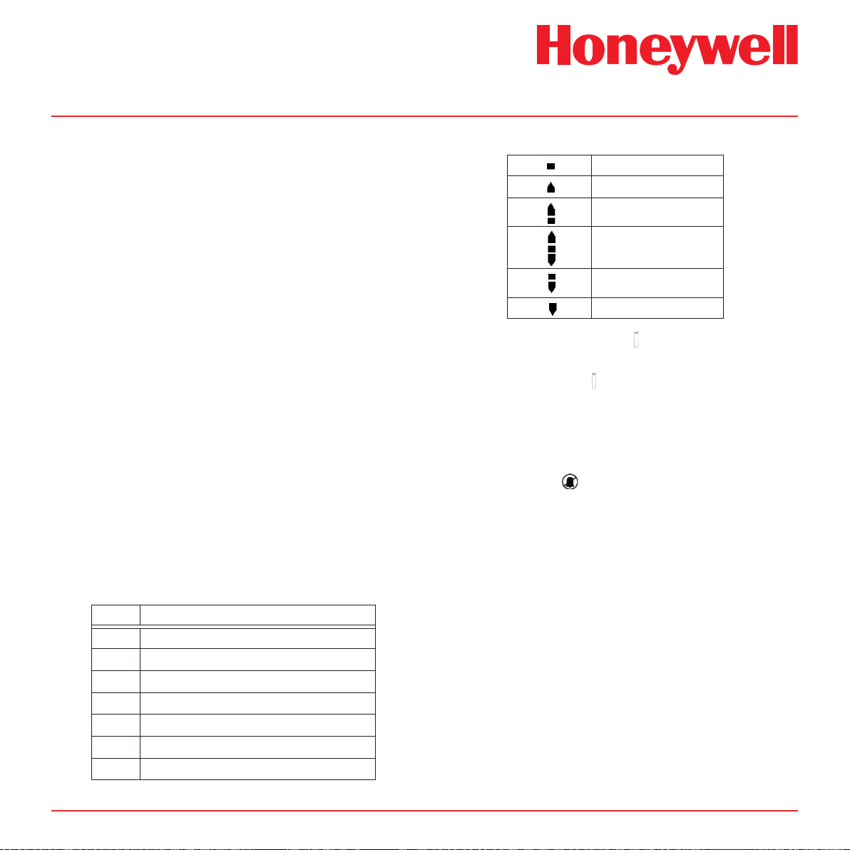
Midas® Gas Detector
7. Press ‘3’ to confirm when ready and the icon
goes steady.
8. Apply the span gas.
9. The dots on the left of the display indicate
progress to a successful span.
10. The display will show the span gas reading
and if measured to be stable for an appropriate
period of time will display ‘PASS’.
11. If the span calibration is unsuccessful then the
display will show an error code (see below).
12. Press ‘3’ to exit.
13. Press ‘s’ up or ‘t’ down to select another
submenu.
14. Press ‘X’ to return to set-up, calibration and
test menu selection.
15. Press ‘X’ again to return to normal operation
Note
The change in the gas bottle icon’s
contents gives an indication as to the
relative stability of the gas reading. The
arrows and bars inside the cylinder indicate
whether it is rising or falling as appropriate
(see table below).
Table 7-5� Calibration codes�
Code Code meaning
PASS Successful Calibration
FL:0H Zero Calibration Timeout - Over Range
FL:0L Zero Calibration Timeout - Under Range
FL:0U Zero Calibration Timeout - Unstable
FL:SH Span Calibration Timeout - Over Range
FL:SL Span Calibration Timeout - Under Range
FL:SU Span Calibration Timeout - Unstable
Table 7-6� Calibration stability icons�
Stable
Over-Range
Unstable-Rising
Unstable-Flat
Unstable-Falling
Under-Range
7�3�3 Flow Calibration ‘ FLoW’
1. Use the ‘s’ up or ‘t’ down buttons to select the
flow calibration ‘ FLoW’ submenu and press ‘3’
to accept.
2. The flow icon with the dot at the bottom starts
flashing in order to tell the user that the unit is
ready to read the zero flow offset.
3. The inhibit ‘ ’ icon is also displayed indicating
that no alarm outputs will be generated during
this process.
4. Press ‘3’ to confirm and the icon goes steady and a
count down from 10 is shown as the zero flow offset
is read.
5. The display will show the flashing flow icon
with the dot approximately 1/2 way up the
icon to tell the user to set the set point
1 flow (500 cc/min).
6. Press ‘s’ up or ‘t’ down keys to adjust the reading
on the external flow meter to the setpoint 1 target
value.
(NOTE: The reading must be +/- 50 cc/
min of target to be accepted).
7. Press ‘3’ to confirm and the target value
flashes.
8. Press ‘s’ up or ‘t’ down to enter the actual
Midas Technical Handbook
7-11
Page 62

Midas® Gas Detector
value read on the external flow meter.
(NOTE: Holding down the button will increase
the increment speed).
9. Press ‘3’ to confirm and the icon goes steady and
a count down from 10 is shown as the setpoint 1
value is read.
10. The display will show the flashing flow icon with the
dot 3/4 ways up to tell the user to set the set point
2 flow (650 cc/min).
11. Press ‘s’ up or ‘t’ down keys to adjust the
reading on the external flow meter to the set
point 2 target value.
be +/- 50 cc/min of target to be accepted).
12. Press ‘3’ to confirm and the target value
flashes.
13. Press ‘s’ up or ‘t’ down to enter the actual
value read on the external flow meter.
(NOTE: Holding down the button will increase
the increment speed).
14. Press ‘3’ to confirm and the icon goes steady and
count down from 10 is shown as the setpoint 2 value
is read.
15. If successful the display shows UPdt (update)
and the flow calibration is complete.
16. Press ‘s’ up or ‘t’ down to select another
submenu.
17. Press ‘X’ to return to set-up, calibration and
test menu selection.
(NOTE: The reading must
original mounting bracket, this calibration procedure
must be followed to assure proper output voltages as
the factory calibration is invalidated.
1. Use the ‘s’ up or ‘t’ down buttons to select the
mA calibration ‘mA 4-20’ submenu and press
‘3’ to accept.
2. The display shows 4.00 mA indicating that the
analog output should be reading 4 mA
3. The inhibit ‘ ’ icon is also displayed indicating
that no alarm outputs will be generated during
this process.
4. Use the ‘s’ up or ‘t’ down buttons to adjust
the analog output to read 4.00 mA.
5. Press ‘3’ to accept.
6. The display will show 20.00 indicating that
thePress ‘3’ to update the changes (UPdt
displayed) and return to step 1.
7. Press ‘s’ up or ‘t’ down to select another
submenu.
8. Press ‘X’ to return to set-up, calibration and
test menu selection.
9. Press ‘X’ again to return to normal operation.
7�3�4 mA Calibration ‘mA 4-20’
This function permits the calibration of the 4-20 mA
output using an external source such as an ammeter.
The purpose of this calibration is to assure the proper
output voltage to activate external alarms/relays.
If the Midas chassis becomes disassociated from its
Midas Technical Handbook
7-12
Page 63

Midas® Gas Detector
7�4 Test Menu ‘ tESt’
The test menu is used to test the detector gas reading
using bump test gas, and for simulation of alarm and
fault display and output operation (relay, analog and
digital). The test submenu also includes the detector
inhibit facility. The test menu comprises of 3 submenus
as shown in the table below.
Caution
When using the Test Mode with the Midas®,
be aware that simulations for alarm and
fault will trigger any connected devices
from the relay, mA, and/or digital outputs
(Modbus /TCP, LonWorks®) as if a real
alarm or fault is present� If you wish to
avoid activating any connected alarms or
devices use the Inhibit mode to prevent an
unwanted alarm�
Table 7-7� Test mode submenus�
Test
Submenu
Bump bUmP
4-20 4-20 mA Stimulate current output
Inhibit Inh
Alarm/Fault SIm Simulate an alarm and fault condition
To select the test menu from normal operation, press
the ‘s’ up button for a few seconds. Enter the pass code
(if set). Use the ‘s’ up or ‘t’ down buttons to select the
test menu ‘ ’ icon and press the ‘3’ accept button.
7�4�1 Bump Test ‘ bUmP’
Display
Icon Test
Bump test detector with inhibited alarm
outputs
Put the unit into/out of an inhibit state and
set inhibit time out
1. Use the ‘s’ up or ‘t’ down buttons to select
the bump test ‘ bUmP’ submenu and press
‘3’ to accept.
2. The inhibit ‘ ’ icon is also displayed indicating
that no alarm outputs will be generated during
this process.
3. Apply the bump test gas and the display will
show the measured gas concentration.
4. Remove the bump test gas and allow the
detector reading to return to zero.
5. Press ‘X’ to exit.
6. Press ‘s’ up or ‘t’ down to select another
submenu.
7. Press ‘X’ to return to set-up, calibration and
test menu selection.
8. Press ‘X’ again to return to normal operation.
Note
In bump test mode, the Modbus/TCP outputs
are not inhibited. Only the 4-20mA and alarm
outputs are inhibited.
The bump gas test is a functional check only.
Consult local guidelines for recommended
best practices. Bump test concentrations
recommended in Section 17 are calculated
to generate a minimum first alarm level
response.
7�4�2 Alarm/Fault Test ‘ SIm’
1. Use the ‘s’ up or ‘t’ down buttons to select the
alarm/fault test ‘ SIm’ submenu and press ‘3’
to accept.
2. The display shows ‘SIm’ and the A1 ‘s’ icon.
3. Use the ‘s’ up or ‘t’ down buttons to select
A1 ‘s’, A2 ‘ ’ or Fault ‘ ’ for test simulation. A
Midas Technical Handbook
7-13
Page 64

Midas® Gas Detector
steady indicates an m9 simulated fault and
a flashing is an F39 simulated fault.
4. Press ‘3’ to select and ‘SurE’ is displayed to indicate
that the next step will activate the selected output
(relay, analog and digital)
5. Press ‘3’ and the display flashes ‘on’ indicating
that the selected output is activated
6. Press ‘X’ to return to step 2 and select a
different output for test.
7. Press ‘X’ to exit.
8. Press ‘s’ up or ‘t’ down to select another
submenu.
9. Press ‘X’ to return to set-up, calibration and
test menu selection.
10. Press ‘X’ again to return to normal operation.
Note:
If latching faults or latching alarms are set up
and either of those are simulated, then the user
will have to reset them with the ‘X’ button in
normal operation mode.
7�4�3 Inhibit State ‘ InH’
1. Use the ‘s’ up or ‘t’ down buttons to select the
inhibit ‘ InH’ submenu and press ‘3’ to accept.
2. The display flashes ‘nonE’ indicating there is
no inhibit currently set.
3. Use the ‘s’ up or ‘t’ down buttons to select
alarm, alarm and fault or all (Alm, AL-Ft or ALL)
output inhibit states. See Table 7-8 for details
of inhibit states.
4. Press ‘3’ to accept the selected inhibit state.
5. Press ‘s’ up or ‘t’ down to set the inhibit
timeout (between 0 minutes and 4 hrs - default
30 minutes).
6. Press ‘3’ to accept (UPdt displayed).
7. The selected outputs will be inhibited until the
inhibit timeout has elapsed.
Note
If the inhibit timeout elapses before the inhibit
state is set back to ‘nonE’ the maintenance
fault code M17 will be displayed.
8. To take the unit out of inhibit, select the inhibit
‘ ’ InH submenu and press ‘3’ to accept.
9. Use the ‘s’ up or ‘t’ down buttons to select
‘nonE’
10. Press ‘3’ to return to the submenu selection.
11. Press ‘s’ up or ‘t’ down to select another
submenu.
12. Press ‘X’ to return to set-up, calibration and
test menu selection.
13. Press ‘X’ again to return to normal operation.
Table 7-8� Inhibit states�
Inhibit
State
None nonE No functions are inhibited.
Alarms
Inhibited
Alarms
and
Faults
Inhibited
Full
Inhibit
Display Function
Alarm events will be detected, but alarm
ALm
AL-Ft
ALL
outputs (relays, 4-20 mA current loop and
Ethernet) will be disabled.
Alarm and fault events will be detected, but
alarm and fault outputs (relays, 4-20 mA
current loop and Ethernet) will be disabled.
All monitoring functions inhibited. No
monitoring is performed and no alarms or
faults (except for Inhibit Timeout) will be
reported.
7�4�4 Stimulate 4-20mA ‘4-20 mA’
1. Use the ‘s’ up or ‘t’ down buttons to select the
Midas Technical Handbook
7-14
Page 65

‘4-20’ submenu and press ‘3’ to accept.
2. The display shows ‘S 04’ indicating a 4 mA
output is being stimulated.
3. Use the ‘s’ up or ‘t’ down buttons to increase
or decrease current as desired in the range of
1 to 21 mA. Displayed as “S xx” = xx indicating
mA current being output.
4. Press ‘X’ to return to the ‘4-20’ submenu
selection.
5. Press ‘X’ to return to set-up, calibration and
test menu selection.
6. Press ‘X’ again to return to normal operation.
Caution
Proceeding with 20 mA stimulation may
cause unexpected alarm activation�
Only authorized operators should perform
this task!
Midas® Gas Detector
This mode cancels itself in 5 minutes�
Midas Technical Handbook
7-15
Page 66

Midas® Gas Detector
8 Routine Maintenance
Midas Technical Handbook
8-1
Page 67

Midas® Gas Detector
8 Routine Maintenance
Midas® is a fully serviceable product designed with
modular components that can be readily replaced by
trained service personnel so as to minimize the time
that the gas detector is not available.
External in-line air filters should be replaced every three
months or more frequently if the system is sampling
in environments that have high levels of particulate
matter or very acidic / wet atmospheres. Similarly, the
internal particulate filter should be replaced once a
year or more frequently if the sample lines are prone
to heavy contamination.
Every sensor cartridge is shipped with a 12 month
warranty and an extended 2 year warranty sensor
cartridge is also available for purchase. All sensor
cartridges are factory calibrated to traceable national
standards before shipment to the end user.
Note that testing or calibrating with the wrong
(incorrect, out of date, non-traceable) calibration
gases, calibration equipment, methods or operating
conditions can actually damage the sensor cartridge’s
lifetime and alter the calibration adversely. Only
qualified calibration technicians should attempt to
calibrate the Midas® gas detector.
Recommended Maintenance Schedule
Component Frequency
Pump 2 years
Pyrolyzer (all models) 1 year
Internal Filter 2 years/as needed
External Sample Line Filter 780248 3-6 months
1991-0147 3-6 months
1830-0055 3-6 months
1830-0027 1 month
Leak Check Leak Check every 6 months
or after pump, pyrolyzer or
internal filter replacement.
Bump Test 6 months
Flow Calibration Flow Calibrate after pump,
pyrolyzer or internal filter
replacement.
See Appendix B for the correct filter requirement for
your application.
Note
The CO2 cartridge’s bias battery will last
only about 9 months. After replacement,
allow at least a day for the cartridge to reach
equilibrium.
Note
For details regarding sensor cartridge
calibration and bump testing method refer
to Section 17.
The internal pump module is designed to operate for
a minimum of 18 - 24 months and it is recommended
that this pump module (part number MIDAS-A-007)
be replaced every 2 years.
Midas Technical Handbook
8-2
Page 68

Midas® Gas Detector
8�1 Sensor Cartridge Replacement
Honeywell Analytics recommends that the sensor
cartridge be replaced without power to the Midas® unit.
If fitting a sensor cartridge to a unit that is powered,
please refer to Section 7.4.3 to inhibit the detector’s
outputs.
8�1�1 Sensor Cartridge Fitting/Replacement
1. Unscrew the thumbscrew located on the
front panel and remove the cover by pulling
it forwards off the main chassis (see Diagram
27).
2. Ensure the power switch on the terminal
module is in the off position.
3. Remove the old sensor cartridge from the unit (if
fitted) by unclipping the two sensor cartridge locking
tabs located either side of the sensor cartridge and
using them to firmly pull the sensor cartridge out
(see diagram 23).
4. Fit the new sensor cartridge by aligning the
pins at the top of the sensor cartridge with the
socket in the sensor cartridge chamber.
5. Carefully push the sensor cartridge into the
sensor cartridge chamber until fully home and
lock in place using the tabs either side of the
sensor cartridge (see diagram 24).
6. Switch the power switch on the terminal
module to the ‘on’ position.
7. Refit the detector’s cover by aligning the
slots either side with the locating tabs on the
mounting bracket assembly and pushing the
cover horizontally until home. Tighten the
thumbscrew located on the front panel (see
diagram 25).
8. Confirm that the LCD messages “LOAd” and
“WArm” are replaced by a zero concentration
display. Confirm that the yellow fault LED is off.
Note
If replacing a sensor cartridge with a different
gas type sensor cartridge the display will
scroll the message ‘ChAngE gAS?’ If you are
changing the sensor cartridge gas type press
‘3’ to accept. If not, t the correct sensor
cartridge. The pass code (if set) must be
entered to change sensor cartridge gas type.
To set the correct gas for a multi gas type
sensor cartridge refer to Section 7.2.2.
Diagram 8-1� Removing detector cover
REMOVING COVER
chassis
midas
Gas Sensor Cartridge
NITROGEN
TRIFLUORIDE
NF3
PN : MIDAS-S-HFX
SN : 0234456670
Use by : 07-09-2006
mounting
bracket
Diagram 8-2. Removing sensor cartridge
chassis
sensor
m
idas
G
as
S
e
n
s
or Car
t
r
idg
e
NITR
OGEN
T
R
IF
LU
O
R
IDE
NF
3
P
N
: MID
AS-S-HF
SN :
X
0
2344566
U
se
7
by :
0
0
7
-
ze
0
9
-2
llwege
006
r anal
ytics
loosen
cover
Midas Technical Handbook
8-3
Page 69

Midas® Gas Detector
Diagram 8-3� Fitting/replacing sensor cartridge
midas
Gas Sensor Cartridge
NITROGEN TRIFLUORIDE
NF3
PN : MIDAS-S-HFX
SN : 0234456670
Use by : 07-09-2006
midas
Gas
Sen
sor Car
tr
idge
NITROGEN
TRIFLUORID
NF3
E
PN
: MIDAS-S-HFX
SN : 0234
456
Use by : 07-
670
09-2006
Caution
When retting the cover to the Midas® unit,
use caution to prevent damage to the RFI
shielding tabs attached to the chassis.
8�2 Pump Replacement
The pump module has been designed to allow easy
replacement. New pump modules, (MIDAS-A-007),
are supplied with new springs, bracket and tubing preassembled for quick release / replacement.
Diagram 8-5� Location of pump module�
Pump module
(MIDAS-A-007)
The following procedure should be followed carefully
and only performed by suitably trained personnel.
1. Isolate the power to the detector.
2. Unscrew the thumbscrew located on the front
panel.
3. Remove the cover by pulling it forward off the
main chassis.
4. Unscrew the two retaining screws located at
the bottom front of the chassis.
5. Pull the main chassis forward to disconnect it
from the mounting bracket assembly.
6. Remove the 4 pump module screws.
Midas Technical Handbook
8-4
Page 70

7. Remove the two fixing clips and disconnect the
tubes at the manifold.
8. Slide the pump module out and disconnect the
connector from the pcb.
Midas® Gas Detector
9. Fit the new pump module following the steps
above in reverse order. Orient the metal
retaining clamps away from the pump wiring to
prevent damage. Route pump wiring away from
the chassis and manifold to prevent damage.
8�3 Reassembling the Detector
1. Align the PCB at the top rear of the main
chassis with the connector located at the top
of the mounting bracket assembly.
2. At the same time align the two tubes at the
bottom rear of the main chassis with the two
tubes located on the bottom of the mounting
bracket assembly.
3. Slide the chassis backwards on the mounting
bracket assembly so that the PCB, connector
and tubes engage simultaneously.
4. Ensure the PCB, connector and tubes are
fully engaged by firmly pushing the main
chassis horizontally backwards on the
mounting bracket assembly.
(WARNING: DO NOT PUSH ON THE LCD
AS THIS MAY CAUSE DAMAGE).
5. Align the two attaching screws located at the
Midas Technical Handbook
8-5
Page 71

Midas® Gas Detector
bottom of the chassis with the screw threads
on the mounting bracket assembly.
6. Tighten the screws to secure the chassis to
the mounting bracket assembly.
7. Switch the power switch on the terminal
module to the ‘on’ position.
8. Refit the detector’s cover by aligning the
slots either side with the locating tabs on the
mounting bracket assembly.
9. Push the cover horizontally until home.
10. Tighten the thumbscrew located on the front
panel.
Note
Honeywell Analytics recommends
conducting a “Flow Calibration” (See
Section 7.3 for instructions)
8�4 Filter Replacement
The internal filter (MIDAS-A-009) has been designed
for easy replacement.
The following procedure should be followed carefully
and only performed by suitably trained personnel.
1. Isolate the power to the detector.
2. Unscrew the thumbscrew located on the front
panel.
3. Remove the cover by pulling it forwards off the
main chassis.
4. Unscrew the two retaining screws located at
the bottom front of the chassis.
5. Pull the main chassis forward to disconnect it
from the mounting bracket assembly.
6. Locate the filter access slot in the side of the
main chassis.
Diagram 8-6� Filter location�
Main chassis
Filter access slot
Filter
(MIDAS-A-009)
7. Carefully disconnect both sides of the filter from
the pump manifold.
8. Remove the old filter and replace with a new
filter ensuring that the filter connectors are fully
engaged in the manifold ports and that the
filter is the correct orientation (arrow pointing
downwards). Orient the metal retaining clamps
away from the pump wiring to prevent damage.
9. Route pump wiring away from the chassis and
manifold to prevent damage.
Midas Technical Handbook
8-6
Page 72

Midas® Gas Detector
Diagram 8-7� Filter orientation�
Filter connector
Manifold ports
➭
New lter
correct orientation
8�5 System Leak Check Procedure
Caution
When performing a leak check, the Midas®
must be placed in inhibit mode to prevent
false concentrations or faults to be activated
when plugging the Sample and/or Exhaust
Lines�
Example: O2 (oxygen) – plugging of the
ports causes the O2 levels within the
Midas® ow path to be depleted as the
sample becomes stagnant� The result is the
concentration levels begin to fall and trigger
the alarms for the O2 depletion�
3. The flow meter indicators will begin to drop
and ultimately disappear (within seconds) (see
Diagram 2-3)
4. Continue to keep the port plugged until
the Midas® reports an “F81” (Flow Fail) –
approximate time to fault is 1 minute
5. Remove the plug
6. Allow 15 seconds or so to allow the Midas®
flow to stabilize then clear the fault by pressing
and holding ‘X’
7. Plug the Outlet Exhaust line
8. The flow meter indicators will begin to drop and
ultimately disappear (within seconds)
9. Continue to keep the port plugged until
the Midas® reports an “F81” (Flow Fail) –
approximate time to fault is 1 minute
10. Remove the plug
11. Allow 15 seconds or so to allow the Midas®
flow and concentrations to stabilize then clear
the fault by pressing and holding ‘X’
12. Return the unit to normal operation
Diagram 8-8� Port Location�
Gas inlet port
1. Place the Midas® into Inhibit (see Section 7.4.3)
2. Plug the Inlet Sample line (see Diagram 8-8)
Midas Technical Handbook
Gas outlet port
8-7
Page 73

Midas® Gas Detector
9 Pyrolyzer Module
Options
Midas Technical Handbook
9-1
Page 74

Midas® Gas Detector
Midas Gas Detector
9 Pyrolyzer Module Options
Two Midas Pyrolyzer modules are available to
detect specific gases (consult the Midas data
sheets for an updated list of detectable species).
The pyrolyzer module option is installed under the
Midas gas detector. An air sample is drawn through
the pyrolyzer and the target fluorinated compounds
are converted into hydrogen fluoride (HF) gas by
means of pyrolysis at a high temperature which is
optimized for each gas family. The residual HF is
then measured by the appropriate sensor cartridge
and the concentration is calculated from this result.
This concentration is then displayed in actual ppm
on the Midas’ LCD display.
The standard Midas pyrolyzer unit (P/N MIDAS-T0P3) detects nitrogen triflouride (NF3 08-03). NF3
pyrolyzer units require a Freon end-of-line filter
Diagram 9-1 illustrates the various pyrolyzer
configurations. This table shows that gases which
can be detected by the Midas Pyrolyzer module.
Detectable Gases
Cartridge
Part No.
MIDAS-E-XHF,
MIDAS-S-XHF
MIDAS-E-XCF,
MIDAS-S-XCF
Gas
NF
CH3F
C4F
C5F
CH2F
SF
Gas
ID
02
3
03
02
6
03
8
04
2
05
6
(P/N 1830-0027). The filter is filled with charcoal to
remove Freon and other similar compounds from the
sample gas before it is “cracked” in the pyrolyzer.
Note that the pyrolyzer module is ideally suited for
leak detection rather than analytical detection of
very low trace amounts of PFC compounds.
Diagram 9-1� Midas gas detector with Pyrolyzer modules MIDAS-T-OP3 (left), MIDAS-T-OOP (center), MIDAS-T-HTP (right)�
Ventilated To p Cover
(MIDAS-A-039)
Midas Technical Handbook
Midas Pyrolyzers
9-2
Page 75

Midas® Gas Detector
Laminar flow element
To maintain sensor accuracy when using the
pyrolyzer, do not allow the ambient temperature
at the point of installation to exceed 30°C (86°F).
Operation above this temperature may require
more frequent bump testing or calibration to confirm
working specification. Because of the higher
operating temperatures when using the pyrolyzer
module, Honeywell Analytics strongly recommends
that the ventilated Midas Top Cover (part number
MIDAS-A-039) be used in all pyrolyzer applications.
NOTE: The Pyrolyzer module is serviceable only by
trained personnel or by Honeywell Analytics’ Service
Center. Inappropriate handling can cause injury and
device damage.
Note: Le module pyrolyzer pouvant-être réparé.
Par contre la réparation doit-être effectuée par
un personnel qualifié ou à un centre de service
autorisé d’Honeywell Analytics. Une manutention
inadéquate pourrait causé des blessures ainsi que
des dommages à l’appareil.
Diagram 9-2 shows the main components of the
pyrolyzer.
Diagram 9-2� Pyrolyzer components�
Diagram 9-2. Pyrolyzer components.
Diagram 9-3 shows in a simple form how a gas
sample is drawn through the pyrolyzer module by
the pump (located at the end of the gas path). It is
first routed to the pyrolyzer via the Freon filter before
being sent to the gas sensor cartridge, where the
gas measurement is taken. The sample continues
via the flow meter through the dust filter and is finally
exhausted from the instrument. Adjustment of the gas
flow through the instrument is done automatically. It is
recommended to perform a leak check (see Section
8.5) before performing a flow calibration. To perform
a flow calibration refer to Section 7.3.3.
Diagram 9-3. Pyrolyzer conguration gas ow.
(Flow measurement)
Pump
Orifice
(Bypass flow)
Pressure sensor
Gas sensor
Pyrolyzer Heater
Pyrolyzer
Midas Technical Handbook
9-3
Gas sample
Exhaust
Freon
filter
Gas sample
Inlet
Needle Valve
(Heater flow adjustment)
Note: Model 0P-3
does not require
flow adjustment.
Page 76

Midas® Gas Detector
sample outlet port
9�1 Fitting the Pyrolyzer Module
1. Disconnect power to the detector.
2. Unscrew the thumbscrew on the front panel.
3. Remove the cover by pulling it forward off the
chassis, as illustrated in Diagram 9-4.
Diagram 9-4� Removing the Midas cover�
chassis
4. Unscrew the two retaining screws located at
the bottom front of the chassis.
5. Pull the chassis forward to disconnect it from
the mounting bracket assembly (see Diagram
9-5).
cover
thumbscrew
retaining screws (2)
mounting bracket
sample inlet port
Diagram 9-5� Removing the chassis�
chassis
mounting bracket
6. Thread the connector and wire harness from
the pyrolyzer through the rectangular access
in the bottom of the mounting bracket.
7. Secure the wires with a retention clip (if
available).
8. Plug the connector into the socket (con5) at
the bottom left of the terminal board.
9. Align the fitting at the top rear of the pyrolyzer
with the sample and inlet ports at the bottom
of the mounting bracket.
Midas Technical Handbook
9-4
Page 77

Midas® Gas Detector
10. Connect the pyrolyzer to the detector with the
three provided mounting screws (see Diagram
9-6).
Diagram 9-6� Attaching the pyrolyzer�
terminal
module
socket
(con5)
connector
tubes
power switch
rectangular access at
bottom of bracket
mounting
screws (3)
pyrolyzer
WARNING To maintain sensor accuracy
when using the pyrolyzer, do not allow the ambient
temperature at the point of installation to exceed 30°C
(86°F)� Operation above this temperature may require
more frequent bump testing or calibration to conrm
working specication. Because of the higher operat-
ing temperatures when using the pyrolyzer module,
Honeywell Analytics strongly recommends that the
ventilated Midas Top Cover (part number MIDASA-039, shown in Diagram
applications�
Note:
Consult the label on the side of the Pyrolyzer
module, as shown in Diagram 9-7, for the
rmware version level required in the Midas
detector for proper operation.
Diagram 9-7� Pyrolyzer labels�
P/N: MIDAS-T-0P3
05/06 REV 3 S/N:00001
For Non-Flammable Gases Only
www.honeywellanalytics.com
9-1) be used in all pyrolyzer
Midas Technical Handbook
This pyrolyzer is to be used only with
Midas Extractive units equipped with
version 1.10 or later application software.
9-5
Page 78

Midas® Gas Detector
?
?
?
??
??
???
?
?
???
?
?
?
?
?
?
?
?
?
?
??
??
?????
???
?
?
?
?
?
?
??
???
?
?
???
??
?
?
?
?
???
??
?
?
?
?
??????
????
?
??
?
?
??
??
?
????
??
??
??
?
??????
?
?
??
?
?
?
?
??
???
?
?
?
chassis
?
?
?
?
?
?
??
?
??
?
??
????
?? ?
?
??
?
??
?
?
?
???
????
?
?
?
?
?
?
??
???
?
????
?
??
?
?
???
?
?
?
?
?
?
?
?
??
?
??
??
?
?
?
?
?
?
?
??
?
?
??
???
?
?
?
?
?
?
?
?
??
?
?
?
?
?
???
?
?
?
???
?
??
?
?
9�2 Reassembling the Detector
1. Align:
a. the PCB at the top rear of the chassis
with the PCB connector at the top of the
mounting bracket and
b. the two tubes at the bottom rear of the
chassis with the two tubes on the bottom of
the mounting bracket.
2. Slide the chassis backward on the mounting
bracket assembly so that the PCB, connector,
and tubes engage fully. Push the chassis
backward on the mounting bracket. CAUTION:
The LCD is fragile� Do not apply pressure to
its surface�
3. Tighten the retaining screws to secure the
chassis to the mounting bracket.
4. Insert the MIDAS-S-HFX sensor cartridge
into the sensor cartridge chamber (see
Diagram 9-8) and refer to the Sensor Cartridge
Installation Quick Start Guide (MIDAS-A-021).
5. Set the power switch to the “on” position.
6. Refit the ventilated top by aligning the slots
on either side with the locating tabs on the
mounting bracket assembly, shown in Diagram
9-9. Push the cover horizontally until seated.
Diagram 9-9. Retting the top cover.
slots (2)
Diagram 9-8� Reassembling the detector�
Midas Technical Handbook
tabs (2)
cartridge
9-6
Page 79

Midas® Gas Detector
thumbscrew
9.3 Conguring the Detector
1. After completion of the startup sequence, press
the “p” button for a few seconds to select the
setup menu.
2. Enter the passcode (if necessary).
3. Use the “p” or “q” buttons to select the setup
menu “ ” icon. Press the “P” to accept.
4. Use the “p”or “q”buttons to select the set
alarms “ ALm” submenu. Press “P” to accept.
5. The flashing gas ID code and the gas cylinder
and alarms icon “ ’’ will appear.
6. Use the “p” or “q” buttons to change the gas
ID number to that of the target gas. Press “P”to
accept.
7. Continue to accept or change the rest of
the alarm settings. For further details on
these settings, refer to the Midas Operating
Instructions (part number MIDAS-A-001).
8. Press “P” to update all changes (“UPdt” will be
displayed).
9. Press “X” twice to return to normal operation.
9�4 Replacing the Pyrolyzer Heater
Block
WARNING: The Pyrolyzer module becomes
extremely hot during operation� Allow it to
cool
before beginning this procedure�
AVERTISSEMENT: Le module pyrolyzer
devient extrêmement chaud à l’usage�
Veuillez alloué une période de refroidissement
avant de débuter cette procédure�
1. Loosen the thumbscrew on the top of the unit as
shown in Diagram 9-10.
Diagram 9-10� Loosening the thumbscrew
After applying power, verify that the sensor cartridge
ID and gas ID are appropriate for the target gas.
See Appendix B for gas ID codes. Refer to Section
7.2.2 for the procedure for setting the gas ID code.
The Midas gas detector automatically detects the
pyrolyzer module and provides the necessary power
and signaling for the device.
Midas Technical Handbook
2. Slide the front cover out of the C-enclosure (see
Diagram 9-11).
Diagram 9-11� Removing the front cover
9-7
Page 80

3. Disconnect the Viton tube from the upper micro
P-clip and lock nut
heater wire connector
Viton tube
C-enclosure
heater block assembly
tube port. Discard the Viton tube (Diagram
9-12). Replacement Viton tubing is supplied
with the new heater block.
4. Remove the P-clip and lock nut.
5. Disconnect the thermocouple and heater wires
from their PCB connectors.
6. Remove the bolt from the manifold assembly.
Diagram 9-12� Disconnecting the heater block
Viton tube
upper microtube port
manifold bolt
Midas® Gas Detector
quartz tube port
thermocouple
connector
7. Disconnect the lower Viton tube from the quartz
tube port. (If necessary, swing the heater unit
as shown in Diagram 9-13.) Discard the old
Viton tube.
Diagram 9-13� Disconnecting the lower Viton tube
Midas Technical Handbook
8. Remove the heater block assembly by first
lifting it up and then sliding it out of the keyhole
connector in the C-enclosure (Diagram 9-14).
Diagram 9-14� Removing the heater block assembly
keyhole
connector
9. Reverse steps 1 through 8 to install the new
heater block assembly.
9-8
Page 81

Midas® Gas Detector
10 Optional LonWorks®
Interface Installation
Midas Technical Handbook
10-1
Page 82

Midas® Gas Detector
Diagram 10-1. Midas® LonWorks® module.
Midas® LonWorks® Module
10 Midas LonWorks® Interface Module
10�1 LonWorks® Installation
Midas® can be directly integrated within a LonWorks®
network using an optional interface module (MIDAST-LON). This gateway provides both power and
communications to the Midas® transmitter and creates
a LonWorks® node on the network. All gas readings,
faults and other sensor data are transmitted via the
LonWorks® protocol. Any Midas® transmitter can be
easily configured to connect with the LonWorks®
interface module.
The Midas® LonWorks® interface module is installed
behind the standard Midas® gas detector as shown
in Diagram 10-1. Power and data connections are
supplied directly to the LonWorks® interface module. All
power to the Midas® unit is provided via the LonWorks®
interface.
Diagram 10-1� Midas® LonWorks® module�
10�1�1 Fitting the LonWorks® Module
1. Unscrew LonWorks® interface top plate.
2. Mount the interface and tighten screws. See
mounting template on reverse side.
3. Connect 24V DC power and LonWorks® wires
to the pluggable connectors. Clamp the cables
in the supplied gland as shown in Diagram 10-
2. A spare gland is included.
4. Reinstall top plate on the interface.
5. Loosen thumbscrew on front of Midas®.
6. Remove unit cover.
7. Loosen two screws on bottom front of chassis.
8. Separate main chassis from mounting bracket
assembly.
9. Mount the Midas® mounting bracket assembly
onto the LonWorks® interface.
10. Tighten screws.
11. Align the PCB at the top rear of the main
chassis with the connector located at the top
of the mounting bracket assembly.
12. Slide the main chassis backwards on the
mounting bracket assembly so that the PCB and
connector and tubes engage simultaneously.
WARNING: DO NOT PUSH ON THE LCD AS
THIS MAY CAUSE DAMAGE
13. Tighten the screws to secure the main chassis
to the mounting bracket assembly.
14. Reinstall cover
Customer Wiring
Midas® to LonWorks® Interface Cable
Midas Technical Handbook
MIDAS-A-040
10-2
Page 83

Midas® Gas Detector
Diagram 10-2� LonWorks Cable Gland�
10�1�2 Wiring the Midas® for LonWorks®
Wiring Diagram
Pwr Common
Pwr +24 VDC
Lon A
Lon B
Pwr Common
Pwr +24 VDC
Lon A
Lon B
Plug 2
Plug 1
5. LonWorks® FT-10 wiring is polarity sensitive.
Lon A and Lon B may be swapped.
10.1.3 Conguring the Midas® for LonWorks®
1. Turn on 24 VDC power.
2. Confirm that the Midas® initiates the power
up sequence.
3. Reset Fault F49 if present.
4. Set alarm levels and other parameters as
desired.
5. Confirm that the Midas® IP parameters are at
default values. If changed, the DHCP client
must be set to ‘n’. The IP address must be
restored to 169.254.60.47 and the subnet
mask must be restored to 255.255.255.0
Wiring Notes:
1. Maximum wire size is 16 AWG.
2. Input voltage range is 20.4 to 26.4 VDC.
3. It is mechanically possible to misalign Plug1
and Plug2. Care must be taken when inserting
plug to assure correct alignment.
4. Plug1 and Plug2 are internally connected in
parallel to facilitate wiring in bus topology.
Midas Technical Handbook
10-3
Page 84

Midas® Gas Detector
10�2 LonWorks® Software
10�2�1 LonWorks® Overview
LonWorks® is a communications protocol developed
by Echelon Corporation which facilitates peer-to-peer
communications in a control network. The Midas®
gas detector is available with an optional LonWorks®
interface.
The Midas® uses the Free Topology (FT) physical layer
which communicates at 78 Kbaud. Each FT segment
can contain up to 64 nodes and up to 2.7 Km of cable.
Routers permit expansion of the network to multiple
segments.
The Midas® LonWorks® interface contains 2 functional
blocks, 19 network variables and 2 network configuration
inputs. It is designed for compliance with LonMark
guidelines version 3.2. However, it is not LonMark
certified. The LonMark representation of the interface
is shown in Diagram 10-3.
Information on LonWorks® can be found at www.echelon.
com. Information on LonMark can be found at www.
lonmark.org. Many commercial LonWorks-compatible
products can be found at www.engenuity.com.
Diagram 10-3� LonMark Diagram
MIDAS LonWorks Gateway Dev ice
Open-loop sensor Functi onal Block
nv1
Mandatory
nviRel ay1
SNV T_lev_ disc
nviRel ay2
SNV T_lev_ disc
nviRel ay3
SNV T_lev_ disc
SNV T_lev_ disc
Implementation-Specific
nviRes et
Node Object Functional B loc k
nv1
cp22
cp24
nviRequest
SNV T_obj_request
Implementation-Specific
nciMaxSendT
SNV T_elapsed_tm
nciMi nSendT
SNV T_elapsed_tm
Virtual Function Bl ock
nv2
Mandatory
nv3
nvoConc
SNV T_ppm_f
nvoAl m2
SNV T_lev_ disc
nvoAl mL
SNV T_lev_ disc
nvoAl mS
SNV T_switc h
nvoAl mThresh1
SNV T_ppm_f
nvoAl mThresh2
SNV T_ppm_f
nvoCell Life
SNV T_elapsed_tm
nvoFaultD
SNV T_lev_ disc
nvoFaultS
SNV T_switc h
nvoGasSelection
SNV T_count
nvoMonState
SNV T_state
nvoNstat
SNV T_state
nvoStatus
SNV T_obj_status
nvoChkS um
SNV T_count
Midas Technical Handbook
10-4
Page 85

Midas® Gas Detector
10�2�2 Network Variable Behaviors
The behaviors of the network variables are as detailed
below:
nvoConc
This reports the concentration of the target toxic or
flammable gas in the SNVT_ppm_f data type. The
concentration will be scaled in ppm when a toxic gas
cartridge is installed. For example a 100 ppb B2H6
concentration will be reported as 0.1. However, when
an O2 cartridge is installed, this will be scaled in volume
percent. For example, normal air will be reported as
20.9, not 209000.0. Furthermore, concentration will be
reported as a percentage of the lower explosive limit
(LEL) for flammable gas cartridges. This means that
CH4 at a concentration of 50% LEL will be reported
as 50.0, not as 25000.0 ppm.
Alarm Outputs
The alarm status of the Midas® is reported in three
network variable outputs (NVOs) for maximum
compatibility. The values of nvoAlmL, nvoAlm2,
and nvoAlmS under various conditions are listed in
Table 1. The variable nvoAlm2 is provided to facilitate
discrimination between alarm1 and alarm2 by 3rd party
actuators which treat SNVT_lev_disc as a Boolean
data type. The variable nvoAlmS is provided to
increase compatibility with Echelon LonPoint modules.
Note that the values stored in nvoAlmL are slightly
different than that of other Honeywell Analytics / MDA
Scientific gas detectors. For example, a Vertex will
indicate a level 1 alarm by ST_MED. This is because
ST_LOW is reserved for small non-zero concentrations
below the alarm threshold. Additionally, the System
16, LIFELINE, LIFELINE II and CM4 indicate a level
2 alarm as ST_MED.
Table 10-1� Alarm Outputs
nvoAlmL
Alarm Status
(SNVT_lev_disc)
None ST_OFF ST_OFF {0.0, 0}
Level1 ST_LOW ST_OFF {0.5, 1}
Level2 without
Level 1 (only
possible with
depletion
alarms)
Level 1 and 2
(usual case)
ST_MED ST_MED {1.0, 1}
ST_HIGH ST_MED {1.5, 1}
nvoAlm2
(SNVT_lev_disc)
nvoAlmS
(SNVT_switch)
nvoFaultD
This has the value ST_MED if an instrument fault exists
and the value ST_LOW if a maintenance fault exists. If
both faults exist, this takes ST_HIGH. It has the value
ST_OFF if no fault exists.
A maintenance fault indicates the Midas® requires
attention but is continuing to monitor. An instrument
fault indicates a loss of monitoring.
nvoFaultS
This network variable output facilitates identifying the
cause of the fault over the network. The .value byte
of SNVT_switch will be the fault number. These are
listed in Section 6 of the Midas® Quick Start Guide.
Additionally, a communication failure will be reported
as fault number 100. The .state byte of SNVT_switch
has the value 1 if any fault exists. Otherwise it takes
the value 0.
Note that the LonMark standard calls for the .value field
Midas Technical Handbook
10-5
Page 86

Midas® Gas Detector
to be divided by two for display. Thus the raw value is
twice the fault number. For example when a flow failure
(Fault F81) exists, the raw value of nvoFaultS will be
{0xA2, 0x01}. This is displayed by LonMark-compatible
tools as {81.0, 1}.
Alarm Thresholds
The variables nvoAlmThres1 and nvoAlmThres2
reports the configuration of the alarm setpoints. The
scaling and format of the data is identical to that used
with nvoConc. These are read-only data – it is not
possible to change the alarm settings over LonWorks®.
nvoGasSelection
This NVO facilitates determining over the network what
cartridge is installed and which calibration is selected.
The most-significant byte of this is equal to the sensor
cartridge ID number. The least-significant byte of this
is equal to the gas ID number. Values for both are
listed in Appendix B.
nvoCellLife
This reports the time remaining until the F43 (“Cartridge
Expired”) is issued. Fault m12 (“Cartridge Expires
Soon”) will generally be issued 30 days before F43.
However, this variable provides no advance warning
of fault m11 (“User Cal Expired”).
Table 10-2� nvoMonState Bit Assignment
bit
bit1bit2bit3bit4bit5bit6bit7bit8bit9bit10bit11bit12bit13bit
0
MSB
Always
Zero
Heartbeat
Counter
Always Zero
Monitoring Mode
Integer
14
bit
15
LSB
The description of the Monitoring Mode Integers are
listed in Table 10-3 below.
Table 10-3� Monitor Mode Integer Description
Monitoring Mode Integer Description
0 Warmup
1 Monitoring without inhibit
2 Alarms inhibited
3 Alarms, and faults inhibited
4 Alarms, faults and concentrations inhibited
5 Simulation
6 Bump test mode
7 4-20 mA calibration mode
8 Other calibration mode
9 to 14 for future expansion
15 Communications failure.
nvoMonState
The bits in this variable are shown graphically in Table
10-2. The least-significant 4 bits form a monitoring
mode integer (MMI). Bit 7-2 form a heartbeat counter
which increments every 2 seconds. The heartbeat
counter is provided to facilitate confirmation of
communication. This variable propagates every
nciMinSendT since it is always changing.
Midas Technical Handbook
10-6
Page 87

Midas® Gas Detector
nvoNstat
This NVO conveys the general status of the gas
detector. The meanings of the 16 bits in this NVO
are defined in Table 10-4. Note that the presence of
a maintenance fault is not conveyed by this variable.
Table 10-4� nvoStat Description
Bit Description
15
In calibration mode
(LSB)
14 In simulation mode
13 Inhibited
12 In warmup mode
11
Always zero, for future expansion
10
9 Alarm 2 active
8 Alarm 1 active
Instrument fault fixable by new car tridge
7
(Faults 39 - 49)
Instrument fault fixable by HA Service
6
(Faults 80, 82 - 89 or comm fail)
5 Flow instrument fault (F81)
4 Always zero, for future expansion
3
Measuring unit
2
1
0
(MSB)
code
Always zero, for future expansion
Bit3=0, Bit2=0: % Volume
Bit3=0, Bit2=1: % LEL
But3=1, Bit2=0: ppm
value is clamped to 180 seconds and 5 seconds,
regardless of the programmed value.
Additionally, every NVO will repropagate when the
status of its function block changes and nciMinSendT
has expired since the last propagation. This has a
default value of 5 seconds. The effective value is
clamped to 10 seconds and 1 second.
nviRelay1, nviRelay2 and nviRelay3
These network variable inputs can be used to control
the three internal relays from LonWorks®. However,
these NVI’s will have no effect unless the Midas® is
configured to respond to network relay commands.
The following procedure lists how to configure the
relays to be remotely controllable:
a) Hold the “s” key for 2 seconds until “SEt” is
displayed.
b) Press the “3” key once to enter the setup menu.
The display should show “ALm”.
c) Press the “s” key once to scroll to fault setup.
The display should show “FLt”
d) Press the “3” key once to enter the fault setup
menu. The display will show one of the four relay
configuration codes shown in Table 5.
e) Press the “s” key as needed to select mode
“nEtr”.
nciMaxSendT, nciMinSendT
These network configuration inputs control the update
rate of the network variable outputs. Every NVO will
repropagate after a period of nciMaxSendT or less.
This has a default value of 60 seconds. The effective
Midas Technical Handbook
f) Press the “X” key repeatedly to exit the setup
menu.
The various relay configuration options are listed in
Table 10-5.
10-7
Page 88

Midas® Gas Detector
Table 10-5. Fault Relay Conguration options
LCD
Symbol
1FLt Instrument fault only Alarm 1 Alarm 2 Inst Fault
2FLt Separate fault relays Any Alarm Maint Fault Inst Fault
CmbF Combined fault relay Alarm 2 Alarm 2 Any Fault
nEtr Network remote mode nviRelay1 nviRelay2 nviRelay3
Description
Source of Signal for Relays
Relay 1 Relay 2 Relay 3
Once the relays are configured for network remote
mode, they will respond to updates to the three
associated NVIs. The values ST_LOW, ST_MED,
ST_HIGH and ST_ON will cause the relays to
energize. The value ST_OFF will cause the relays to
de-energize. The configuration settings for “normally
energized” and “normally de-energized” have no effect
if the relays are in network remote mode. However,
the relays can still be configured for normally open or
normally closed contacts by moving the jumpers on
the Midas® backplane PCB.
Caution
Several failure modes will cause the relays
to de-energize� These modes include power
failures and CPU lockups� Furthermore,
power must be removed from the Midas® for
certain maintenance procedures� External
equipment should be designed to prevent
creation of expensive or dangerous conditions
when the relays de-energize� For applications
requiring a highly-reliable digital output,
Honeywell Analytics recommends purchasing
a dedicated DO device�
nviRequest
Updates to this NVI have the effects listed in Table
10-6. These requests are usually sent by the network
management tool.
Table 10-6� Request Implementation
Request
0 RQ_NORMAL Set to enabled Send “no inhibit” command
1 RQ_DISABLED Set to enabled Send “inhibit all” command
2 RQ_UPDATE_STATUS Retransmit status Retransmit status
3 RQ_SELF_TEST
4 RQ_UPDATE_ALARM
5 RQ_REPORT_MASK Send capability report
6 RQ_OVERRIDE
7 RQ_ENABLE Set to enabled Equivalent to RQ_NORMAL
8 RQ_RMV_OVERRIDE
9 RQ_CLEAR_STATUS
10 RQ_CLEAR_ALARM
11 RQ_ALARM_NOTIFY_ENABLE Equivalent to RQ_NORMAL
12 RQ_ALARM_NOTIFY_
DISABLE
13 RQ_MANUAL_CTRL
14 RQ_REMOTE_CTRL
15 RQ_PROGRAM
16 RQ_CLEAR_RESET
17 RQ_RESET
-1 RQ_NUL
Node Object
Implementation
Sensor Object
Implementation
Send “reset alarms and
faults” command
Send “inhibit alarms”
command
nviReset
This network variable input causes alarms and faults
to be reset when it is updated with ST_LOW, ST_MED,
ST_HIGH or ST_ON.
Midas Technical Handbook
Note that disabling the node object has no practical
effect. (This is implemented only for LonMark
compatibility.)
10-8
Page 89

Midas® Gas Detector
nvoStatus
The meaning of the status bits in this NVO is as listed
in Table 10-7.
Table 10-7� nvoStatus Implementation
LonMark Field
Name
object_id (16 bits) 0
invalid_id ID > 1
invalid_request
disabled disabled inhibited
out_of_limits
open_circuit
out_of_service
mechanical_fault instrument fault
feedback_failure
over_range alarm 2
under_range
electrical_fault maintenance fault
unable_to_measure
comm_failure communication failure to Midas
fail_self_test communication failure to Midas
self_test_in_progress warmup mode
locked_out
manual_control
in_alarm any alarm
in_override
report_mask mere capability report mere capability repor t
programming_mode
programming_fail
alarm_notify_disabled inhibit, warmup or calibration
reset_complete
Node Object
Intrpretation
unimplemented request
made
Sensor Object interpretation
unimplemented request made
®
®
nvoChkSum
This network variable indicates the checksum of the
neuron chip and is included to confirm the correctness
of the program. This will have the value 32533 for
Revision 1.0 software. This is computed 45 seconds
after power-up.
10�2�3 Other Characteristics
WINK Command
The LonWorks® “wink” command causes the service
LED to energize for approximately six seconds.
LED Interpretation
All LED operation is inhibited for 35 seconds after
power-up. This is because the neuron is held in reset
until the internal ARM-7 microprocessor boots. If
the neuron is “unconfigured”, after 35 seconds the
yellow service LED will flash slowly. If the neuron is
“configured” the service LED will be dark.
The interface contains a second LED which can be
useful for debugging. This is red in color and only
visible when the lid is removed from the interface. It is
labeled D15 and is located immediately below the black
FT-X1 transformer on the PCB. D15 will blink every
second when the neuron is executing code correctly.
This will be “on” most of the time if communication to
the Midas® is successful. It will be “off” most of the
time if communications to the Midas® is unsuccessful.
Communications is certain to be unsuccessful for 190
seconds after power-up due to the Midas® boot time.
Midas Technical Handbook
10-9
Page 90

Caution
After commissioning, Echelon’s LonMaker
tool will put this device into the “ofine”
state� In this mode, the Midas® interface
will not transmit over LonWorks®� To
correct this, it is necessary to click-right,
on the device, select “Manage” and click on
“Online”
Compatibility with old LonMaker
This device is observed to work incorrectly with
Echelon LonMaker for Windows version 3.00.66. This
is because it was created with NodeBuilder version
3.1 and contains an XIF file in format version 4. The
problem is manifested as network variables having
the wrong direction – outputs appear as inputs. The
problem can be corrected by replacing a file in the
network management tool with a new version. This
file is “C:\LonWorks\bin\XIF32Bin.exe”. Echelon has
granted permission for this file to be copied freely.
A copy of this file can be obtained from Honeywell
Analytics on request.
Midas® Gas Detector
Midas Technical Handbook
10-10
Page 91

Midas® Gas Detector
11 Troubleshooting and
Fault Diagnosis
Midas Technical Handbook
11-1
Page 92

Midas® Gas Detector
11 Troubleshooting and Fault Diagnosis
General trouble shooting guide and specific fault code table for Midas® with Version 1.08 or lower software.
Table 11-1� Fault code descriptions�
Fault
code
m9
m10
m11
m12
m13
m14
m15
m16
m17
F39
F40
F41
F42
F43
F44
F45
F46
F47
F48
F49
F80
F81
Description Condition Recovery
Simulated maintenance fault User has generated a simulated fault. Reset simulated fault.
Over range. A large concentration has been detected. The
User calibration expired. The user specified calibration interval has elapsed. Perform zero and span calibrations. Increase span calibration period.
Cartridge expires soon. Cartridge is old and will expire soon. Replace the cartridge with a new cartridge.
Flow error. Midas® is no longer able to regulate flow (high or
Interferent present. An interferent is degrading the ability of the Midas®
Temperature near limit. Temperature within 2 Celsius of limit. Check installation environment.
Baseline fault. Sensor baseline has drifted. Check for background gas concentration, temperature or humidity fluctuations.
Inhibit timeout. Transmitter has been in inhibit mode too long. Resume monitoring or increase timeout value.
Simulated fault User has generated a simulated fault. Reset simulated fault.
Sensor overdosed. Sensor has been exposed to high gas
Baseline fault. Sensor baseline has drifted. Check for background gas concentration, temperature or humidity fluctuations.
Calibration expired. Too long since last calibration. Replace or calibrate the cartridge.
Cartridge expired. Cartridge is too old. Replace cartridge.
Cell failure. Cartridge has failed Reflex™ check. Replace cartridge.
Stabilization timeout. Cartridge has failed to stabilize. If temperature or humidity shocks exist, precondition the car tridge. Check for
Cartridge analog failure. Electronic Failure or gas concentration greater than
Cartridge memory invalid. Checksum error. Replace cartridge.
Cartridge absent. No communications. Reseat cartridge. Replace car tridge.
Cartridge wrong type. Cartridge type found to be incorrect after boot-up. Replace cartridge or press ‘3’ accept if correct.
Temperature limits exceeded. Temperature is outside limits Check installation environment.
Flow fail. Flow < 70% of nominal for 15 seconds. Check filters. Check for kinked tubing, Replace pump.
Midas® requires an independent confirmation that
the gas hazard is gone.
low flow condition).
to detect gas.
concentrations for long periods.
full scale.
Supply known clean air to the Midas® and clear this fault.
Check filters and pump.
Check pressure at inlet and outlet and assure they are within specification.
(See Section 4.3 Sample and exhaust tubing calculations)
Check application.
Perform zero calibration. Replace cartridge.
Replace cartridge.
Perform zero calibration. Replace cartridge.
background gas concentration. Replace car tridge.
Replace cartridge.
Midas Technical Handbook
11-2
Page 93

Midas® Gas Detector
Fault
code
F82
F83
F84
F86
F87
F88
F89
F90
F91
F92
Description Condition Recovery
Excessive electrical noise. Internal electronics repeatedly noisy. Check grounding of Midas® chassis. Check termination of cable shields.
Pyrolyzer fail. Pyrolyzer fails to heat. Check electrical connection to pyrolyzer. Replace pyrolyzer. (also see Section
Misc. transmitter fault. Transmitter is defective. Service or replace Midas®.
Coprocessor fail Coprocessor is damaged. Contact Honeywell Analytics Service.
Pyrolyzer temp limits
exceeded
Pyrolyzer heater fail Pyrolyzer heater failed. Contact Honeywell Analytics Ser vice. Replace the pyrolyzer.
Pyrolyzer power unreg Target power not achieved within specified time
Pyrolyzer heater mismatch Different pyrolyzer type required Contact Honeywell Analytics Service.
HTP module required Check that MIDAS-S-CFX or MIDAS-E-CFX is
0P3 pyrolyzer module failure
Pyrolyzer temperature exceeded. Clean pyrolyzer cooling vents. Contact Honeywell Analytics Service.
span.
installed for the high temperature pyrolyzer version
Data value: 0x0800
0P3 pyrolyzer failed to get up to temperature
Data value: 0x1000
0P3 pyrolyzer flow is out-of-range
Data value: others
0P3 pyrolyzer internal failure
Relo
cate the Midas® further from noise sources. Add ferrite inductors to cables.
4.3)
If 24VDC power check, 21.6 < V in < 26.4 Contact Honeywell Analytics Service.
Replace pyrolyzer.
Change to HT Pyrolyzer
Replace pyrolyzer heater
Check flow connections between Midas and 0P3 pyrolyzer
Contact Honeywell Analytics Service.
“Hot” and “Cool” messages are informational events that can be generated under two conditions:
1. Immediately after the detector powers up.
2. When the state changes from cool to hot or hot to cool.
“Hot” means the temperature inside the cartridge is at 40°C or above. “Cool” means the temperature inside the
cartridge is below 40°C. In both cases the event data field will list the actual temperature at the time of the event.
Midas Technical Handbook
11-3
Page 94

Midas® Gas Detector
12 Reex
®
Midas Technical Handbook
12-1
Page 95

12 REFLEX®
Midas® uses patented Honeywell Analytics technology
to continuously monitor the health check status of
specic electrochemical cells and alert the user if a
cell enters a variety of fault conditions (such as open
or short circuit etc.) which would leave the cell unable
to detect gas and raise an appropriate alarm signal.
REFLEX® overcomes this unseen failure mode by
applying periodically a special electronic pulse
to the cell and reviewing the ‘echo’ from the cell
as it responds to the applied signal. If the cell is
deteriorating within certain pre-set limits based on
the received signals then Midas® will decrease the
REFLEX® sampling interval in order to establish the
actual viability of the cell. Within a relatively short time,
Midas® will be able to alert the user via fault codes
that the electrochemical cell is likely to be requiring
replacement and is possibly unable to correctly detect
gas.
Midas® Gas Detector
REFLEX® is not required for pellistors or oxygen
electrochemical cells as these sensor cartridges
provide alternative electronic means to indicate open
circuits and other sensor cartridge damage issues.
Midas Technical Handbook
12-2
Page 96

Midas® Gas Detector
13 Internal Web Server
Midas Technical Handbook
13-1
Page 97

Midas® Gas Detector
13 Internal Web Server
The Midas® gas detector unit utilizes an Ethernet port
with the TCP/IP protocol as standard. The Midas® can
function as a HTML web page server and these web
pages can be viewed on external computer equipment
(PC, PocketPC etc.) by using a standard software
program, i.e.; Microsoft Internet Explorer. These web
pages replicate the user interface on the front panel
of the Midas® in a more flexible and friendly format for
diagnostic and data entry purposes. The web pages
also contain additional features not available via the
keypad.
This procedure explains how to view web pages for a
single Midas® which is connected to a single PC only.
Of course it is possible to connect hundreds of Midas®
units to an Ethernet network. More information may be
required from the local IT department and Honeywell
Analytics as appropriate.
13�1 Physical Network Components
The Ethernet 100BaseT physical network is intended
to connect computers to other computers through
hubs. For this reason, a Midas® cannot communicate
directly with a PC using a standard cable. This problem
can be overcome by using a special “cross-over”
Ethernet cable or by using a ‘hub’ or ‘switch’ and two
standard (straight through wire connections) Ethernet
cables. An example of a cross-over cable is the Belkin
A3X126 family. An example of an Ethernet switch is
the Linksys SD205.
server, the addresses must be set manually. To view
or set the IP address of the Midas®, see Section 7.2.6.
The procedure for setting the IP address of a PC is
detailed in the following example using a PC loaded
with Microsoft™ Windows XP and Internet Explorer
version 5.0 or higher as illustrated by Diagram 13-1.
In the usual case the netmask for both computers
should be set to 255.255.255.0. The most-significant
three bytes of the IP address must be identical and the
least-significant byte must be unique. For example, if
the IP address of the Midas® was set to 169.254.60.47
(the factory default) then an appropriate IP address for
the PC would be 169.254.60.42.
13�2 Internet Settings
Communications requires knowledge of the IP address
and netmask of both the Midas® and the PC. Unless
the Midas® is connected to a network with a DHCP
Midas Technical Handbook
13-2
Page 98

Midas® Gas Detector
Diagram 13-1� IP Address setting in Windows XP�
Midas Technical Handbook
13-3
Page 99

Midas® Gas Detector
13�3 Running the Web Browser
Start Microsoft™ Internet Explorer or similar web browser. Set the URL to “http://xxx.xxx.xxx.xxx” where the “xxx”
fields are replaced with the IP address of the Midas®. A screen similar to Diagram 13-2 should be displayed.
The status and configuration of the Midas® can be viewed and set by clicking on the appropriate links.
Diagram 13-2� Midas® Default web page�
On the Status web page, all faults and alarms are indicated as well as real-time concentration reading. A
fault or alarm can be reset from within the web page by clicking the “Reset” button. If the fault condition is
still present, the fault status will be indicated again on the web page. Information regarding alarm settings,
calibration history and software version are all contained in the status web page.
Midas Technical Handbook
13-4
Page 100

Diagram 13-3� Event History�
Midas® Gas Detector
All Midas® events including calibrations, faults, and
alarms are data logged with a timestamp, description
and category code. The events are color-coded to allow
a quick overview of the type of event logged.
Color Event Type
Green Reset
Red Alarms
Yellow Fault
White Informational
Midas Technical Handbook
13-5
Event History will store approximately 400 events,
overwriting the oldest with the newest data. 30
seconds of data is stored for each alarm event - 15
seconds before the event and 15 seconds after.
The “Send to Print”, will generate a printed version
of the event log by page or the complete listing (see
Diagram 13-5).
The “Details” button allows access to a graphical
display of gas concentration versus time elapsed (see
Diagram 13-6).
 Loading...