

Page 1

Protocol for Testing Toxic Gas
1998-0219 Rev 5 August 2012
Technical Note
Introduction
This protocol provides a method to evaluate the performance of toxic gas detectors. A
worksheet is included; this is a useful guide in recording the performance of gas detection
sensors. It is also useful as part of a maintenance log for complete gas detection systems.
To understand the merits of specific gas detection equipment, several parameters must be
tested. These factors include response time, environmental conditions, affects of temperature,
accuracy and sensitivity to potential interfering substances, recovery time, failure indication,
stability (drift) and repeatability over time. Test conditions must simulate the real world;
therefore the test conditions must simulate the working environment (temperature and
humidity). Supplies and materials must be selected accordingly.
The gases utilized may be very toxic. It is therefore essential that a thoroughly trained
safety engineer or industrial hygienist be responsible for the generation of these gases
and that the gas is generated in a well-ventilated area and exhausted safely.
Equipment and Test Gas
1. Zero Air for zero calibration
In applications where the ambient air is normally containing a low level of target gas,
some sensors may require zero calibration with “clean air”.
a. Compressed air
(Filtered through activated charcoal to remove most of unwanted gases and water
vapor)
b. Zero Air in Lecture bottle
2. Span Gas for Bump Test and Calibration
To achieve the best accuracy, a mixture of the target gas balanced in the background
environmental air is the best calibration gas. However, it usually requires that the
operators be more skilled, with precise equipment and reference standard method to
analyze the gas concentration. The following are recommended methods of gas setup
for bump and calibration.
Technical Note 1998-0219
Page 1 of 12
Page 2
Technical Note
a. Disposable Calibration Gas Bottle
(Low pressure, premixed with Air or Nitrogen)
This method with fixed flow or demand flow regulator is easiest and practical way to
bump test EC sensors (both extractive system and passive sensor wit h calibration
cap or flow housing).
For extractive sampling systems when the concentration of gas lecture bottle is
higher than the detection range, test gas can be diluted with fixed flow rate regulator
and T fitting in sample line. Use fixed flow regulator having lower flow rate than
extracting sample flow rate and attached clean air bag at T fitting. (ex. Using 0.25
L/min regulator with clean air at T fitting, the sample test gas concentration for a
MIDAS with ~0.5 L/min flow is approximately half of the concentration of bottle.)
A zero air lecture bottle with fixed flow regulator can be used for dilution (and use
another T fitting to vent overflow with extractive systems). This method would also
work with passive detection systems.
The lecture bottle dilution method is suitable only for bump testing as the gas mixture
accuracy depends on the flow rate precision.
The type and concentration of calibration gas, sample tubing, flow regulators and
calibration adapters are key links in the calibration chain. The instrument can only be
as accurate as the gas used to calibrate it.
As concentration stability and shelf life is dependent on the mixture of gas and bottle
type, do not use uncertified and/or expired gas cylinders. Most highly reactive
chemicals are mixed with nitrogen.
Check that all gas wet materials including regulator and tubing are preconditioned
with the gas sample before applying gas to sensor.
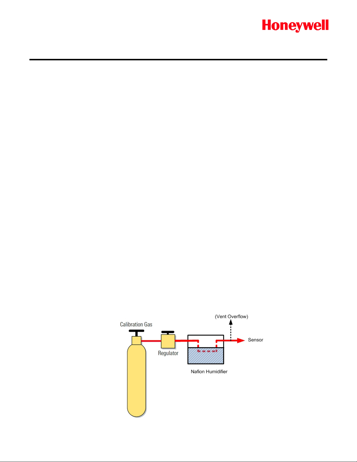
Some sensors may need moisture to get a proper reading. A humidifier, such as a
“Nafion®” humidifier, can be added in sample line. Check the compatibility of the
humidifier with the target gas before use.
Technical Note 1998-0219
Page 2 of 12
Page 3

Technical Note
b. Sampling Bag (Tedlar or Teflon)
This method is good for both extractive systems and non-reactive gases fill i ng fr om a
gas cylinder, diluted gas, or permeation device. Some gas bag materials are
permeable and have gas adsorption characteristics.
c. Permeation/Diffusion Device
A permeation device has some advantages over a calibration standard cylinder;
providing precise concentrations and a wide range of concentrations easily generated
by varying the dilution flow rate and or the set point of oven temperature.
At a known rate of permeation and a given temperature, a constant flow rate of air
mixed with the permeated chemicals forms a constant stream of calibration gas. A
calibrator with constant temperature and flow regulation is needed. Portable
permeation devices are commercially available.
Prior to use, permeation devices should be conditioned at the calibration temperature
and carrier flow to bring the rate to its equilibrium value. Most devices require 30
minutes to 3 hours to reach equilibrium. Heavy wall tubes, low vapor pressure
compounds, and halogenated compounds typically take longer. The best procedure is
to set up the calibration system the day before it is needed, allowing the system to
equilibrate overnight. Conduct repeated tests over a period of time to ensure that
equilibrium has been achieved. Test gas can be filled in a sample gas bag, or feed
sample gas to passive sensor, or extract test gas directly connecting at T fitting in
Span with Overflow (Vent) output mode.
There may be an activated charcoal scrubber for carrier/dilution air before the
permeation chamber in commercially available portable permeation gas generator; the
generated test gas will be dryer than ambient air, requiring additional humidification
(such as Nafion® humidifier) for some gases and sensors.
d. High Pressure Gas Cylinder
High-Pressure Cylinders are designed for hazardous chemicals and for high
concentration mixture which is much stable than above mentioned methods.
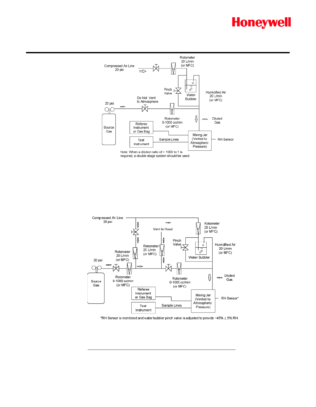
d-1. High Pressure Gas Cylinder - Single Stage Dilution Method
This method is good for both passive or extractive system, and Gas Bag filling for
remote test. Schematics of the recommended gas generation and dilution system
are provided in Figures 1 and 2.
Figure 1 shows a typical single stage dilution gas generation rig. This is best
utilized when diluting c once nt rat e d cyli nd er s at rati os bel ow 10 00-to-1.
Technical Note 1998-0219
Page 3 of 12
Page 4
Technical Note
d-2. High Pressure Gas Cylinder - Double Stage Dilution Method
This method is good for both passive or extractive system, and Gas Bag
filling for remote test.
Figure 2 shows a typical double stage dilution rig. This is utilized for diluting
cylinders at ratios greater than 1000-to-1. Double stage dilution is the best
method when generating low level concentrations is required.
The concentration of calibration gas can be calculated as follows:
Concentration (ppm) =
Cylinder Flow (cc/min) * Cylinder Concentration (ppm)
Total Flow [Cylinder +Dilution F low] (cc/min)
Note:
Multiply gas concentration in ppm units by 1000 to obtain concentration in ppb units.
Technical Note 1998-0219
Page 4 of 12
Page 5

Technical Note
Performing a Bump Test or Calibration
Gas should be supplied from a reliable source. To achieve accuracy and consistency, it must
be assured that the source is stable and within date code (e.g. for cylinders and permeation
tubes).
Whenever possible, primary target gases should be used for calibration. Cross-calibrations
(non target gases which can cause a quantifiable response, but that are typically easier to
handle) should be used only when gas detection manufacturers confirm accuracy of response.
It is better if these cross-cali brat ions be used for semi-quantitative or qualitative work, such as
triggering alarms and relays.
If cylinder gas is used, a “referee” method must be used to ensure that accurate concentrations
are being produced. Even certified cylinders may not provide the expected gas concentration,
especially after storage. Good laboratory practice indicates the use of a referee method. It
should also be noted that high quality permeation devices can provide excellent accuracy for
many gases.
For most applications, the sample gas should be prepared using humidified dilution air (to
approximately 30-60% RH; with 45% RH being optimal). This simulates real world conditions
that are likely to be encountered during an actual event. All materials must be selected to
ensure that any "wetted" surfaces in contact with the supplied gas are inert to the compound
being tested. For example, when supplying HCl, tubing, fittings and all other wetted surfaces
should be constructed of FEP Teflon; stainless steel is not appropriate, since it will react with
HCl and other common industrial gases at ppm concentrations.
Active / sample-draw instruments often pull high volumes of sample (several liters per minute).
The volume of test gas generated must exceed or exactly match the monitor’s sample flow
intake.
When using low volume permeation devices to test these instruments, it will be necessary to
collect several liters of sample gas in a Tedlar® or Teflon® bag (refer to Table 1 for gas
suitability); then draw the sample gas from the bag. This bag could typically be 100 liters in
size. For some reactive, adsorptive gases the sample bag should be preconditioned to
establish equilibrium between the sample gas and the surfaces of the bag. This will help to
ensure that the concentration of the generated gas is maintained. The material of the bag
should be suitable for the target gas; since some reactive gases may be adsorbed onto some
materials. The bag should be checked with a referee method to ensure appropriate
concentrations and efficient transfer from the sour c e.
The sample line should be kept as short as 5ft, minimizing the transport time and reducing
adsorption effects for sensor performance test.
For passive (non-sample draw) sensors, the manufacturer's recommended calibration cap
(flow-through housing) should be used. In order to simulate typical field conditions, NIOSH
protocol suggests a minimum face velocity. The face velocity is calculated by dividing the flow
rate by the cross-sectional area of the flow housing.
Technical Note 1998-0219
Page 5 of 12
Page 6

Technical Note
Table 1 provides guidance when selecting gas generation equipment. The gases that are listed
are commonly found or used in industrial environments. Information on these compounds is
included to satisfy the need for cross-interferenc e tes ti n g.
If cross-interferences are present in ambient air or in the dilution air, another source of clean,
humidified air or nitrogen should be used.
The mass flow controlled output should be verified against an independent flow calibrator. A
primary standard bubble flow meter can be utilized for this purpose.
Technical Note 1998-0219
Page 6 of 12
Page 7

Tubing and other
with sample gas
Ammonia (NH3)
Aluminum cylinders, N2 balance;
device
FEP Teflon,
Refer to Note 1.
Arsine (AsH3)
Aluminum cylinders, N2 balance,
mass flow controller
FEP Teflon®,
polypropylene, Kynar®,
brass
Boron Trifluoride
Aluminum cylinders, N2 balance
with Teflon gasket; stainless steel or
use is not allowed.
FEP Teflon and Monel
Do not use sample bags.
utilized regardless of generation
Carbon Monoxide
Aluminum cylinders; stainless
or Monel mass flow controller
FEP Teflon,
Tedlar, Monel, brass
Chlorine (Cl2)
Aluminum cylinders, N2 balance;
FEP Teflon, Kynar
Stainless steel and most other
Nafion® can be used.
Diborane (B2H6)
Aluminum cylinders, N2 balance,
mass flow controller
FEP Teflon,
Hydrogen (H2)
Aluminum cylinders; stainless steel
mass flow controller
FEP Teflon,
Kynar, Monel, brass
Do not use Tedlar bag.
Hydrogen Bromide
Aluminum cylinders, N2 balance;
FEP Teflon, Kynar
Stainless steel and most other
Refer to Note 2.
Hydrogen Chloride
Aluminum cylinders, N2 balance;
FEP Teflon, Kynar,
Stainless steel and most other
be used, high purge flow req’d.
Technical Note
Table 1. Calibration Considerations for Common Gases
Gas Source(s)
stainless steel or Monel regulator,
mass flow controller, Permeation
stainless steel regulator with
Teflon® gasket; stainless steel
(BF3)
(CO)
stainless steel or Monel regulator
Monel mass flow controller.
Permeation devices are best
method for field testing if cylinder
steel regulator; stainless steel
stainless steel regulator; corrosive
mass flow controller. Permeation
device
materials in contact
polypropylene, Kynar
Tedlar®, Monel®,
polypropylene, Kynar,
Special considerations
Do not use Nafion® humidifier
(Note 3).
Refer to Note 2
Referee instrument must be
method to verify concentration.
metals are not acceptable.
Concentration in cylinders may
not be stable.
Do not use Tedlar bag.
See Note 1.
Refer to Note 2. Note 3;
stainless steel regulator with Teflon
gasket; stainless steel or Monel
regulator; stainless steel or Monel
(HBr)
(HCl)
regulator with Teflon gasket and
corrosive mass flow controller.
Permeation device
regulator with Teflon gasket and
corrosive mass flow controller.
Permeation device
polypropylene, Kynar,
Tedlar, Monel, brass
polypropylene,
metals are not acceptable.
Diffusion vials are
recommended.
Do not use sample bags.
metals are not acceptable.
Do not use sample bags
Diffusion vials are
recommended.
Refer to Note 2.
Note 3; Nafion® humidifier can
Technical Note 1998-0219
Page 7 of 12
Page 8

Tubing and other
with sample gas
Hydrogen Fluoride
Aluminum cylinders, N2 balance;
FEP Teflon, Kynar,
Stainless steel and most other
Nafion® can be used.
Isopropyl Alcohol
Syringe injection into gas bag
FEP Teflon,
Tedlar, Monel, brass
Readily available liquid.
Humidifier.
Phosphine (PH3)
Aluminum cylinders, N2 balance,
mass flow controller
FEP Teflon,
Silane (SiH4)
Aluminum cylinders, N2 balance,
mass flow controller
FEP Teflon,
Difficult to achieve high
Technical Note
(HF)
(IPA)
Gas Source(s)
regulator with Teflon gasket and
corrosive mass flow controller.
Permeation device
stainless steel regulator with
Teflon gasket; stainless steel
stainless steel regulator with
Teflon gasket; stainless steel
materials in contact
polypropylene, Kynar,
polypropylene, Kynar,
Tedlar, Monel, brass
polypropylene, Kynar,
Tedlar, Monel, brass
Special
considerations
metals are not acceptable.
Do not use Tedlar bags.
Refer to Note 2. Note 3;
Do not use Nafion®
volumes with permeation
devices.
Notes
1. Permeation d evices have low volu me output. Gas b ags need to be use d to acc umulate th e large s ample
volumes needed for gas t esting. Fill and flush Teflon bag several ti mes for reactive gas conditioning,
and use the gas within 30 minutes.
2. Gas Cylinder regulator must be dedicated to the gas type and to be clea n and kept dry, and require a
long time for conditioning to get stable gas concentration.
3. Nafion® humidifier can be used for all above mentioned test gases except Ammonia and IPA.
Response Time
Response time may be measured in three basic ways.
1. One method of response time specification is provided as follows:
e.g.: T90 = x seconds; e.g.: T50 = y seconds
The term T90 provides the amount of time in which 90% of the actual concentration is
reported. The term T50 provides the amount of time required in which 50% of the actual
concentration is reported. In essence a T100 time would provide the time it takes to
indicate the true concentration of gas present.
2. A second method of providing response time is the amount of time required to indicate a
1 TLV concentration of gas when a 1.6 level of gas has be en appl ied (T62.5). This is the
standard method of specifying response times in Japan.
3. The third way is to simply state the response time. This generally indicates the amount of
time required to display an accurate reading of the actual concentration (similar to the
T100 concept described above). This provides a straightforward specification for accurate
response indication.
Test the speed of response throughout the useful life of the sensor, as the response time
of a sensor may change as the detector ages. The sensor should be tested just prior to
Technical Note 1998-0219
Page 8 of 12
Page 9

Technical Note
the calibration or replacement of the existing sensor. This test indicates, before
adjustment, how well a sensor has been performing during the time it has been in
service.
Note:
Some detectors may need to be "conditioned" before they will reasonably respond to
gas. The response time should be noted for the first application of gas. Under field
conditions there is normally no target gas present, so it is important to replicate this by
taking the data upon the first exposure of the sensor to the target gas.
Accuracy, Drift and Repeatability
Accuracy is tested by comparing a known concentration against the stabilized reading of the
sensor with a known concentration of test gas. This test should be performed before calibration
and several months after calibration to ensure that the instrument will perform acceptably
throughout its life.
Any calibration adjustments that are made to the detector are primarily done to ensure
accuracy at the time of calibration. On occasion the detector may be adjusted t o prov i de a
quicker response by sacrificing accuracy; the instrument will read higher than the actual
concentration.
Drift occurs when, under a no-gas condition, any non-zero readings are observed. Drift can add
to, or subtract from, the reported concentration. Excessive drift can cause false alarms, false
negative readings, or instrument faults.
Repeatability describes how closely a sensor can read to a gas concentration that it previously
reported. This test does not necessarily ensure accuracy.
Lowest Detectable Limits
The Lowest Detection Limit (LDL) is important. Several manufacturers provide a published
range of detection, but they do not provide this minimum detection limit. The capability to detect
low level concentrations under operating conditions means earlier detection, before a small
leak becomes a significant pr obl em .
Cross-Sensitivity to Potential Interferences
Many areas that require toxic and combustible gas detection have the potential for other, nontarget gases to be present. These potential interferences include solvents (eg.: acetone,
isopropyl alcohol), ammonia, hydrogen, hydrogen peroxide and carbon monoxide. Some
interferent gases may have a permanent poisoning effect on the sensor. Consult product
literature on cross-sensitivity information.
As previously indicated, potential interferent gases which are easier to handle are sometimes
used to test or calibrate sensors. This may not be an accurate method of calibrating, since the
correlation factor may dep end on the characteristics of the individual sensor.
Life Testing
Several of the above sections include testing for performance characteristics that need to be
Technical Note 1998-0219
Page 9 of 12
Page 10

Technical Note
checked upon initial installation. These parameters should also be checked just prior to
maintenance. It is important to check these parameters before and after maintenance. After a
period of three or six months, the detector should perform virtually as well as it did during its
last calibration.
Other Performance Considerations
Performance considerations are not limited to those outlined above. Other features of a gas
detector which should be considered include real-time failsafe fault or failure warnings,
verifiable proof of the gas release, ownership costs, suitability for environment, cross
interference or drift issues, and EMI/RFI susceptibility.
Technical Note 1998-0219
Page 10 of 12
Page 11

Sensor Serial Number/ I.D.:
Location:
Gas Type:
Testing to be repeated before
recalibration on (date):
Test Procedure
Results
Calibration
Results
Calibration
Results
Calibration
Results
Calibration
Date:
Tested By:
Verified By:
Zero Reading:
Response Time:
T50:
T90:
T100:
Time (sec) to TLV given 1.6 TLV gas:
Accuracy:
Actual Gas Concentration:
% deviation:
Recovery Time:
Time (sec) to return to zero after test gas is
removed:
Other Considerations:
Potential Interferents:
Proof of Gas Presence? (y/n):
Lowest Detectable Limit:
Resolution (ppb or ppm):
EMI/RFI susceptibility? (y/n):
Self Diagnostics/Failsafe Capability:
Technical Note
Gas Testing Checklist
Immediately
Before
Immediately
After
3 Months
After
6 Months
After
Note:
The last four items may not be easily verified in the field. Individual manufacturers may
need to be consulted.
Technical Note 1998-0219
Page 11 of 12
Page 12

Technical Note
Data may change, as well as legislation, and you are strongly advised to obtain copies of the most recently issued regulations, standards and guidelines.
This publication is not intended to form the basis of a contract and the company reserves the right to amend the design and specification without notice.
While every effort has been made to ensure accuracy in this publication, no responsibility can be accepted for errors or omissions.
www.honeywellanalytics.com
Find out more
Contact Honeywell Analytics:
Americas
Honeywell Analytics Inc.
405 Barclay Blvd.
Lincolnshire, IL 60069
USA
Tel: +1 847 955 8200
Toll free: +1 800 538 0363
Fax: +1 847 955 8210
detectgas@honeywell.com
Europe, Middle East, Africa
Life Safety Distribution AG
Weiherallee 11a
8610 Uster
Switzerland
Tel: +41 (0)44 943 4300
Fax: +41 (0)44 943 4398
gasdetection@honeywell.com
Asia Pacific
Honeywell Analytics Asia Pacific
#508, Kolon Science Valley (I)
187-10 Guro-Dong, Guro-Gu
Seoul, 152-050
Korea
Tel: +82 (0)2 2025 0307
Fax: +82 (0)2 2025 0329
analytics.ap@honeywell.com
Technical Services
ha.us.service@honeywell.com
www.honeywell.com
Technical Note 1998-0219
Page 12 of 12
 Loading...