

Page 1
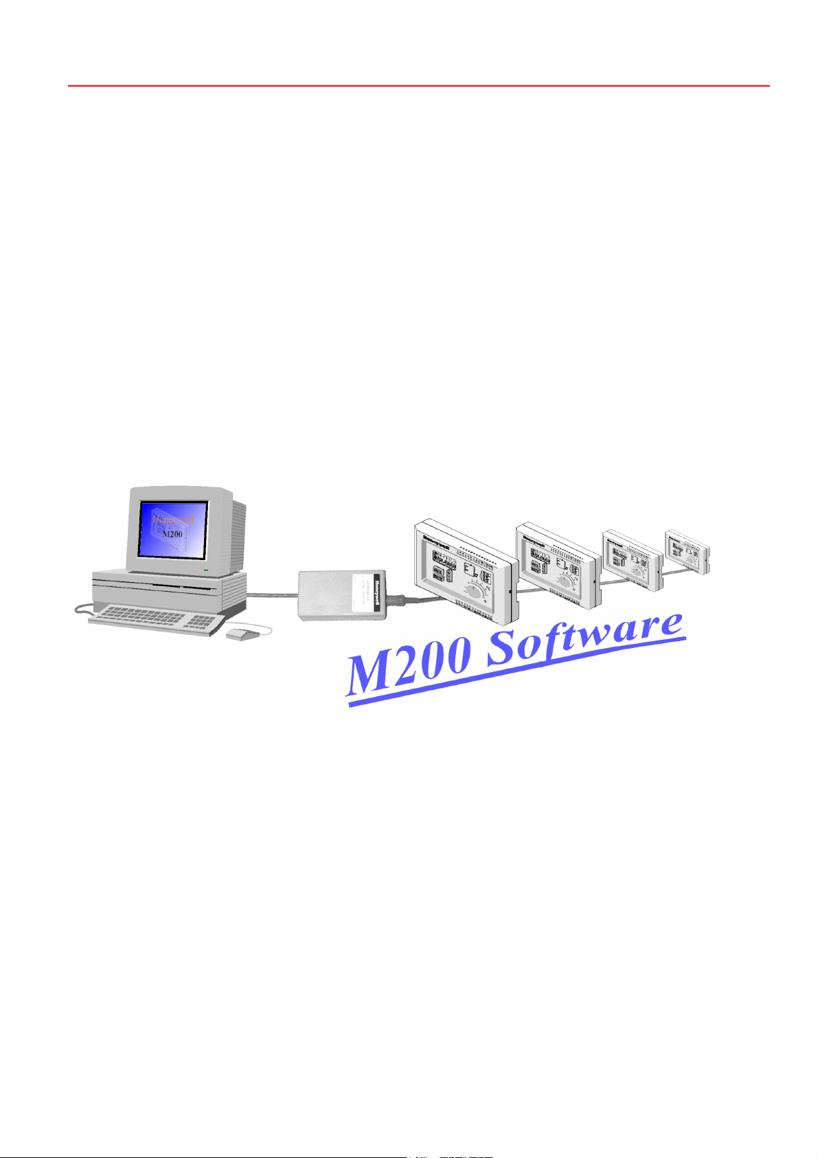
MicroniK 200
HONEYWELL
Operator's Terminal
USER GUIDE
EN2B-0212GE51 R0102
Page 2

OPERATOR'S TERMINAL
EN2B-0212GE51 R0102
Page 3

CONTENTS OPERATOR'S TERMINAL
CONTENTS
Software installation.....................................................................................................................................................................1
Hardware installation ...................................................................................................................................................................1
Screen Layout and Functions......................................................................................................................................................2
Menu Overview .............................................................................................................................................................................7
The Main Menu.......................................................................................................... 2
Controllers on Bus ..................................................................................................... 3
Controller Selection ...................................................................................................3
Controller Name ........................................................................................................3
Control Parameter Setting ......................................................................................... 3
Main Menu Graphic...............................................................................................4
Controller Restart.................................................................................................. 4
Controller Configuration............................................................................................. 4
Fixing Inputs ..............................................................................................................4
Fixing Outputs............................................................................................................4
Graphic Display of Control Functions - Optimization of Control Performance........... 4
Status Overview of All Inputs and Outputs of Controllers on the Bus........................5
Parameter Reset to Factory Programmed Default Values ........................................5
Setting of Controller Date and Time ..........................................................................5
Daily, Weekly Time Schedules and Holiday Schedules ............................................5
Save of Control and Configuration Parameters in Data File...................................... 5
Copy of Control and Configuration Parameters from a Data File .............................. 5
Main Temperature Monitoring within Programmed High and Low Limit Values ........6
Printing of Main Menu................................................................................................ 6
Update of Programmed Control and Configuration Parameters................................ 6
Program Exit..............................................................................................................6
Production Date Code ...............................................................................................6
[Load Default] ............................................................................................................7
[Read M200-Parameter] ............................................................................................ 7
[Options] ....................................................................................................................7
[M200]........................................................................................................................ 8
Saving and Copying the Control and Configuration Parameters .......................... 8
Saving M200 Parameters in a Data File ..........................................................8
Copying All Parameters from a Data File into a Controller ..............................8
Copying Schedules from a Data File into a Controller ..................................... 9
Copying Schedules from a Data File in all Controllers..................................... 9
Deleting a Data File..........................................................................................9
Setting of Date and Time in All Controllers...........................................................9
Search Functions..................................................................................................9
Menu Exit..............................................................................................................9
[Room Table] ........................................................................................................... 10
[Graphics] ................................................................................................................11
Buttons................................................................................................................ 11
Input and Output Value Trend Log of One or Several Controllers ...................... 12
Displaying Control Characteristic over Time (Trend Log)................................... 12
Printing a Graph.................................................................................................. 13
Menu Reduction.................................................................................................. 13
Stopping the Trend Log ......................................................................................13
Displaying the Trend Log....................................................................................13
Graphic Menu Exit ..............................................................................................13
[Status Display of All Controllers on the Bus] .......................................................... 14
Menu Reduction.................................................................................................. 15
Menu Exit............................................................................................................15
[Schedule]................................................................................................................ 15
Buttons................................................................................................................ 15
Daily, Weekly, and Holiday Schedules ...............................................................16
Programming Weekday Schedules ....................................................................16
Programming Holiday Schedules........................................................................16
Setting Time and Date ........................................................................................ 17
Setting the Summer / Winter Daylight Saving Time Period ................................17
Menu Exit............................................................................................................17
[Monitoring]..............................................................................................................17
i EN2B-0212GE51 R0102
Page 4

OPERATOR'S TERMINAL CONTENTS
Setting Monitoring Limits .................................................................................... 18
Low and High Limit Monitoring ........................................................................... 18
Monitoring Concept............................................................................................. 18
The OFF, Night, Standby, and Comfort Controller Modes.................................. 18
Monitoring a Control Characteristic ....................................................................19
Activating/Deactivating Monitoring...................................................................... 19
General Report ................................................................................................... 19
Report Sorting .................................................................................................... 19
Printing Report.................................................................................................... 19
Deleting Report................................................................................................... 19
Menu Exit............................................................................................................ 19
Index ............................................................................................................................................................................................ 20
EN2B-0212GE51 R0102 ii
Page 5
INSTALLATION OPERATOR'S TERMINAL
SOFTWARE INSTALLATION
System requirements
Installation Execute Setup.exe from the CD Drive.
• Pentium 100 min.
• Win 95 / Win 98 / NT
• Resolution 600*800 min.
• Memory: 16 MB min.
• PC Mouse
• CD Drive
• Excel Adapter (43 192 580-401) including the connector plug for the Bus and
24 Vac supply
This will automatically install the M200 interface S/W on the Hard Disk and the
M200 icon to initialize the Operator´s interface.
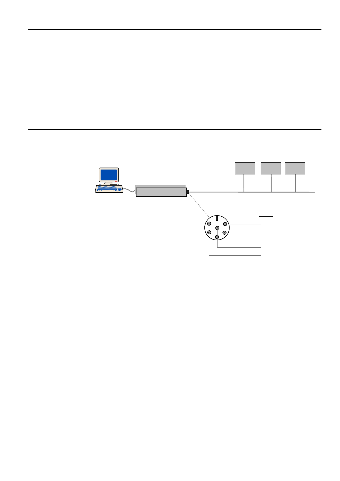
HARDWARE INSTALLATION
M200 M200M200
Excel- Adapter
M 200
External Connector
- front view -
14
13
Bus
18
4 VAC
19
Connect the Bus and the 24 Vac to the Excel Adapter as shown above.
Interconnect all M200 controller terminals 13.
Interconnect all M200 controller terminals 14.
Interconnect all M200 controller terminals 18 (24 Vac).
Interconnect all M200 controller terminals 19 (24 Vac).
Connect the RS232 plug of the Excel Adapter to the PC port (1 or 2).
Switch on power to the M200 controllers and adjust the Bus address (C22) directly
on each controller connected to the Bus (start with address 1).
Initialize the interface by double click on the M200 icon. Then click on (Options) and
select the port (Excel Adapter) and the language English or Deutsch.
1 EN2B-0212GE51 R0102
Page 6
OPERATOR'S TERMINAL SCREEN LAYOUT AND FUNCTIONS
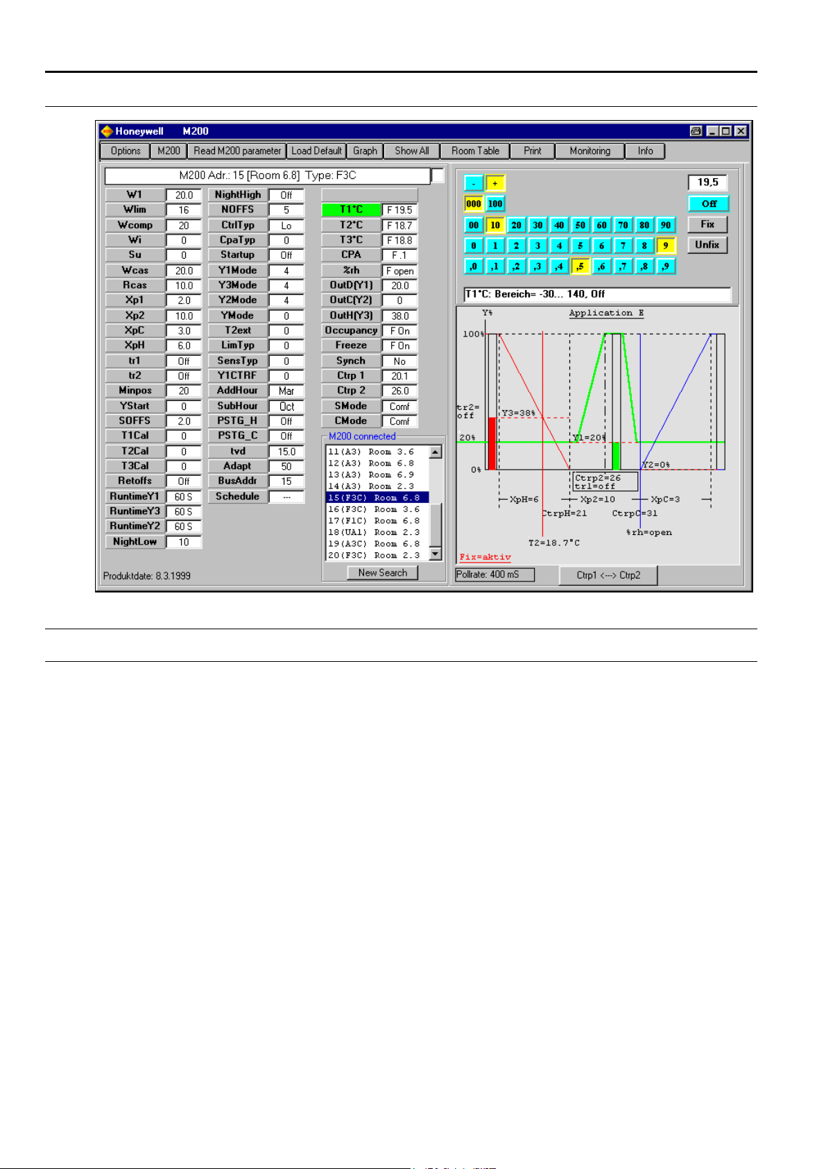
SCREEN LAYOUT AND FUNCTIONS
The Main Menu
After the start of program, the main menu appears as shown above .
All settings are carried out with the left-hand mouse button.
The language selection English or Deutsch can be done in the menu [Options].
EN2B-0212GE51 R0102 2
Page 7

SCREEN LAYOUT AND FUNCTIONS OPERATOR'S TERMINAL
Controllers on Bus
After the start of the program there is an automatic search for the controllers on the
bus and in the display "M200 connected" appears.
If none or not all controllers are displayed here, test the following:
• The serial input on the PC (COM1 or COM2), on which the Excel adapter is
connected, must be set in the menu [Options] (see Chapter [Options] on page 7)
(default = COM1).
• If several controllers are on the bus, their bus address must be adjusted directly
on the controller. Select parameter C22 on the controller and adjust the bus
address. Adjust the Bus address in ascending order starting with address ”1”.
• If there are more than 32 controllers on the bus, modify the maximum number of
controllers in the menu [Options], see Chap. [Options] on page 7. In order to not
slow down the program execution, do not input a greater number than absolutely
required. The addresses can be assigned between 1..253.
• Check the 24VAC and bus wiring.
Controller Selection
In the list "M200 connected", all identified controllers are displayed (bus address
Controller types: F1C = R7426A2014 F3C = R7426B2012
and controller type).
A3C = R7426C2010 UA1 = R7426D2000
To carry out settings on a specific controller, select the controller by a mouse click.
The graphic display application, as well as the parameter list, indicate the controller
settings.
Controller Name
A name can be assigned (max. 13 characters) to every bus address (e.g. building,
room number etc.).
Use the menu [Room Table] for this, see Chap. [Room Table] on page 10.
Control Parameter Setting
The individual controller parameters are selected from the parameter list by mouse
click. Then, on the upper-right in the main menu, the table appears for setting the
parameters (in addition the selected parameter flashes in the graphics display).
The parameters can be adjusted with a mouse click or in the edit field with the
keyboard. The setting range of a parameter is displayed in the lower line. Every
modification of the parameters is immediately transferred to the controller and read
out again from the controller. The value transferred successfully is displayed in the
parameter list.
For controllers equipped with Real Time Clock, the settings of the Operation Modes
and times are carried out in a separate menu. For this, click on the parameter
[Schedule] see Chap. [Schedule] on page 15.
EN2B-0212GE51 R01023
Page 8

OPERATOR'S TERMINAL SCREEN LAYOUT AND FUNCTIONS
Main Menu Graphic
The following is displayed in the graphic display application:
• Configuration of the controller
• Inputs of the controller T1, T2 etc.
• Outputs of the controller Y1, Y2, Y3
• Unusual operating status are displayed in red text
• The parameter currently selected is represented in flashing mode
• In the case of Cascade control, the button [Ctrp1 <--> Ctrp2
the display is switched between the two control loops, master and slave.
• In the case of Wlim control the button [Ctrp1 <--> T2
changed with this.
] appears. With this,
] appears. The display is
Controller Restart
[Restart M200]
This display is not always available.
If the parameters 'Runtime' or 'Mode..' have been changed, a restart of the
controller is necessary. The connected valve and damper actuators are then
synchronized.
If, after setting the parameter, the display [Restart M200] appears, carry out the new
start with a button click, after all parameters have been adjusted.
Controller Configuration
Refer to the relevant literature for the functions of the individual controller
parameters.
Fixing Inputs
The input values T1, T2, T3, CPA, %rh, Frost Thermostat, Presence Switch and the
Switch On/Off, can be fixed. With selection of one of these inputs and the input
value, all inputs are fixed.
Fixing an individual input is not possible.
To cancel the fixing click on [Unfix].
Fixing Outputs
The controller outputs Y1, Y2 and Y3, can be fixed. With selection of one of these
outputs and the value, the respective output is fixed.
To cancel fixing, click on [Unfix] for the respective output.
Graphic Display of Control Functions - Optimization of Control Performance
The inputs/outputs of each individual controller can be recorded with the menu
[Graph] see Chap. [Graphics] on page 11.
Input / output value trendlogs help start-up personnel to verify the controller
operation and to optimize the control performance. With the menu [Graph], the user
can select the inputs/outputs and controllers to be recorded.
EN2B-0212GE51 R0102 4
Page 9

SCREEN LAYOUT AND FUNCTIONS OPERATOR'S TERMINAL
Status Overview of All Inputs and Outputs of Controllers on the Bus
Mouse click on [Display All] see Chap. [Status Display of All Controllers on the Bus]
on page 14.
In this menu, the inputs and outputs of all controllers can be viewed graphically.
In addition, the setpoint temperatures (Parameter W1) of the individual controller
can be adjusted from here.
Parameter Reset to Factory Programmed Default Values
To reset all parameters of the controller to factory setting, click on [Load Default].
Setting of Controller Date and Time
Only for controllers with Real Time Clock function.
There are two possibilities to adjust the time in the controller:
1. Button click on parameter [Schedule]. In the schedule menu, adjust the date and
time manually for the currently selected controller, or transfer directly the PC
time and date into the controller.
2. Button click on [M200] and transfer the PC time and date simultaneously to all
controllers located on the bus.
Daily, Weekly Time Schedules and Holiday Schedules
Only for controllers with Real Time Clock function.
Button click to parameter [Schedule
With this function, the different Operation Modes and the Time Schedules can be
programmed.
] see Chap. [Schedule] on page 15.
Save of Control and Configuration Parameters in Data File
In the menu [M200], see Chap. [M200] on page 8, the settings of a controller can be
stored in the PC. All settings (including schedule) are stored, Every time the
controller data is stored into an individual file. Assign an unique file name (max. 8
characters) for this. In addition, a "Note" containing a more detailed description can
be defined (define the "Note" before storing!).
Copy of Control and Configuration Parameters from a Data File
Menu [M200], see Chap. [M200] on page 8.
The data stored in a file can be loaded into the controllers as follows:
• Copy all parameters (including schedule) into an individual controller.
• Copy only schedule into an individual controller.
• Copy schedule to all controllers
EN2B-0212GE51 R01025
Page 10

OPERATOR'S TERMINAL SCREEN LAYOUT AND FUNCTIONS
Main Temperature Monitoring within Programmed High and Low Limit Values
Menu [Monitoring] see Chap. [Monitoring] on page 17.
The temperature T1 of every controller can be monitored for minimum and
maximum values.
The maximum deviations in each case are recorded in a list.
Printing of Main Menu
The parameter values and the display are printed out on the Windows standard
printer by a mouse click on [Print].
Update of Programmed Control and Configuration Parameters
[Read M200 parameter]
The parameter values are read and displayed automatically with selection of a
controller.
However, if the parameter values of a selected controller vary directly on the
controller, the controller parameters need to be read again.
Alternatively, reselect the controller from the table "M200 connected".
Program Exit
Close the main program with the Windows button [X].
All menus, which are still open, will be closed and the program terminated.
Production Date Code
The Production date (Date Code) of the controller is displayed at lower-left corner in
the main menu.
EN2B-0212GE51 R0102 6
Page 11

MENU OVERVIEW OPERATOR'S TERMINAL
MENU OVERVIEW
[Load Default]
The factory set default parameter settings are loaded into the M200 controller. As a
result, all changed parameters are overwritten.
[Read M200-Parameter]
The parameter values are read automatically and displayed with selection of a
controller.
However, if the parameter values of a selected controller vary directly on the
controller, the controller parameters need to be read again.
Alternatively, reselect the controller from the table "M200 connected".
[Options]
[Port ] Input of COM port number (1-4), at which the Excel adapter is connected.
[German/English] Selection of language, English or German.
[Last Bus address] The individual Bus address of the controllers should be adjusted in ascending order
[Exit] Leave menu.
starting with 1....
The automatic search for the controllers begins from Address 1. Set last bus
address to the number of controllers present on the bus (highest controller
address). Setting of a higher number will unnecessarily slow down the program.
(Default=32).
7 EN2B-0212GE51 R0102
Page 12

OPERATOR'S TERMINAL MENU OVERVIEW
[M200]
Saving and Copying the Control and Configuration Parameters
Saving M200 Parameters in a Data File
The settings of a controller can be stored in the PC. All settings (including schedule)
are stored every time into an individual file. Assign a dedicated file name (maximum
8 characters) for this. In addition, a Note with a more detailed description can be
assigned (assign the Note before storing!).
Procedure:
• Select controller in the table "M200" with a mouse click.
• Enter desired file name into the edit field. The extension ".M20" is appended
automatically and need not be entered.
An already-existent file name can be overwritten by clicking on the
corresponding file in the list "file".
• In the field "Note", insert comments about this file.
• With a mouse click on [---->], all controller data are stored in the file.
The files can be copied also to or from another computer. These are stored under
..M200\Data\xxx.M20 and have the extension .M20.
Copying All Parameters from a Data File into a Controller
Copying all parameters (including schedule) into an individual controller.
• This is useful if a controller has been replaced and the previously stored settings
have to be loaded into the new controller or, if there are several identical
controlled systems, the data of an adjusted controller have to be loaded into the
other controllers.
Procedure:
• Select file to be transferred with a mouse click in the table "file"
• Select the controller into which the data should be transferred with a mouse click
in the table "M200"
EN2B-0212GE51 R0102 8
Page 13

MENU OVERVIEW OPERATOR'S TERMINAL
• With a mouse click on [<----] all parameters (including schedule) are transferred
to the controller.
Copying Schedules from a Data File into a Controller
Copy weekly and yearly schedule into an individual controller. The controller
parameters are not transferred here.
Procedure:
• Select file to be transferred with a mouse click in the table "file"
• Select the controller into which the data should be transferred, in the table
"M200" with a mouse click.
• With a mouse click on [<---- Schedule] the schedule will be transferred to the
controller.
Copying Schedules from a Data File in all Controllers
Copy weekly and yearly schedule into all controllers. The controller parameters are
not transferred here.
By this function, the schedule can be programmed in a controller and then
transferred to all other controllers. (Store controller parameters in a file --> transfer
schedule to all controllers)
Procedure:
• Select file to be transferred with a mouse click in the table "file"
• The schedule is transferred to all controllers by a mouse click on [Schedule to all
M200].
Controllers without clock function are not effected.
Deleting a Data File
• Select file through mouse click in the table "File".
• The file is deleted by mouse click on [Delete].
Setting of Date and Time in All Controllers
The PC time is transferred to all controllers by a mouse click on [PC-Time to all
M200]
Search Functions
No settings are usually carried out here by the user.
The Autosearch [Search all], for general data transfer, must always be active.
In case of major bus malfunctions, it is possible to search manually for a specific
bus address.
[Search single] Single search of the controller.
[Search all] Start automatic search.
[Stop] Stop automatic search.
[Clear list] Deletion of M200 list. The search for controllers on the bus is restarted and thus
Search all M200 addresses on the bus.
This search is started automatically on startup of the program.
The search is continuously carried out and the result of this search employed for all
parts of the program.
controllers, which are no longer available on the Bus, are not displayed anymore.
All graphic records currently running are terminated.
Leave this menu through a mouse click on [Exit].
Menu Exit
EN2B-0212GE51 R01029
Page 14

OPERATOR'S TERMINAL MENU OVERVIEW
[Room Table]
A name can be assigned to every bus address (e.g. building, room number etc.).
This allows to identify the individual controllers in the list more easily.
A name containing a maximum of 13 characters can be assigned. To display the
currently assigned names in the individual screens or the display "M200
connected", click onto [New Search]. The inputs are stored in the PC and are
available again with a new start of the program. To transfer these entries into
another computer, copy the file "..M200\Data\Room.mdb" into the other computer.
Procedure:
• Select bus address through mouse click in the table.
• Write the name to be assigned and store with <Return> button.
• Select next bus address etc.
EN2B-0212GE51 R0102 10
Page 15

MENU OVERVIEW OPERATOR'S TERMINAL
[Graphics]
1 2
3
4
5
101112131415161718
Buttons
1) Graphics display. Y1, Y2, Y3, %rh refers to scaling 0%..100%
2) Move cursor with the mouse. The data of this location is displayed in 7).
3) Move display vertically.
4) Zoom display vertically.
5) Move display horizontally.
6) Zoom display horizontally.
7) Data of cursor position 2).
8) Select curves to be represented. This has no influence on the storage of the data.
(All data are always stored). The colors can be changed by a double-click.
9) Time-setting for measuring cycle.
10) List of the selected files.
11) Print graphics.
12) Stop selected recording.
13) List of controllers on the bus. A mouse click starts the recording.
14) To M200 search menu.
15) List of the measurement files generated.
16) Show selected file in the display.
17) Notes of the selected file. Additional Notes can be entered here.
18) Delete selected file (only if this is not currently being displayed).
6
7
8
9
EN2B-0212GE51 R010211
Page 16

OPERATOR'S TERMINAL MENU OVERVIEW
Input and Output Value Trend Log of One or Several Controllers
The controllers on the bus are displayed in the table "M200" (13).
Select one or more controllers, to be recorded from this table with a mouse click. All
data of the controllers selected are now recorded.
The selected controllers can now be viewed in the table "Display" (10).
A file is simultaneously created in which all data is stored. These file names can
now be viewed in the table "File" (15).
Format of the file names:@M200Adr_seqnumber.mdb e.g. "@3_012.mdb" =
M200Adr. 3 ; sequence no. 12
Stored in ..M200\Data
In the field "File, Note" (17) the automatically generated commentary regarding this
file can be viewed.
Additional commentary can be written into this field. Note that the desired file is
selected in the field "file".
Select the value for the intervals at which the data should be entered. This setting is
valid for all currently running records. Do not select recording times too short, since
a lot of PC disk space will be required for recording over a longer period. Approx.
110 bytes are required for every measurement.
Displaying Control Characteristic over Time (Trend Log)
The values for Y1, Y2, Y3 and %rh are represented in display field (1) in the range
0..100%. All other values are marked over the entire range.
Select controller If several controllers are recorded simultaneously, select the desired display
Select curves With keyboard (8), select the curves which you would like to view. (This selection
Adjust color of the curves Through a mouse double-click in keyboard (8), the colors of the individual curves
View individual measuring data The red line (2) is positioned by a mouse click in display field (1). This line can also
Zoom display horizontally With the buttons (6) the display can be zoomed in the horizontal direction.
Move display horizontally The display can be moved in the horizontal direction with buttons (5).
Display mode: scroll If the display is moved to the end of the measurement, the curve is displaced
Zoom display vertically With the buttons (4) the display is zoomed in a vertical direction.
Move display vertically The display can be moved in a vertical direction with buttons (3).
through a mouse click in the table "Display" (10).
does not affect the recording or the storage of the data.)
can be selected.
be moved by clicking on it and moving the mouse while keeping the left-hand
mouse button depressed.
The measured data is displayed in field (7), located below it.
A mouse click on the arrow zooms step by step, while a mouse click on [+] or [-]
zooms to maximum or minimum size.
Zooming is done in such a way, that the red line always remains (if possible) on the
current measurement.
A mouse click onto the arrows moves step-by-step, while a mouse click on
maximum buttons moves the display (left and right) to the beginning or end of the
measurement.
continuously to the left during recording, so that the current measurement is always
displayed.
If the display is moved in such a way that the last measurement cannot be seen in
the display, a standing display appears.
A mouse click onto the arrows zooms step by step, while a mouse click on [+] or [-]
zooms to maximum or minimum size.
A mouse click onto the arrows displaces step-by-step, while a mouse click on
maximum buttons (up and down) moves the display fully up or down.
EN2B-0212GE51 R0102 12
Page 17

MENU OVERVIEW OPERATOR'S TERMINAL
Printing a Graph
A mouse click on [Print] (11) prints the display on the Windows standard printer. It
is recommended to employ a color printer.
Menu Reduction
To work with another menu or program without terminating the recording, reduce
the size of the menu.
Use the Windows buttons and for this.
Stopping the Trend Log
Select the recording to be terminated in the table "Display" (10) and click on [Stop
recording].
To terminate all recording, close the menu with the Windows button [X]
Displaying the Trend Log
Automatically created files during recording, can be displayed at any time.
For this click on the corresponding file in the table "File" (15) and then click on
[Show file] (16). The file can then also be viewed in the table "Display" (10) and can
be selected there for display.
Close the menu with the Windows button [X].
All records in this menu are terminated properly.
(The M200 program is not terminated with this.)
Graphic Menu Exit
EN2B-0212GE51 R010213
Page 18

OPERATOR'S TERMINAL MENU OVERVIEW
[Status Display of All Controllers on the Bus]
After the start of this menu, all controllers on the bus are displayed.
The following are displayed: T1, T2, T3, Xw, Y1, Y2, Y3, W1
The setpoint value W1 of the controller can be changed by editing the window (next
to W1).
(Keyboard:Enter value and press <Return>)
[Arranging windows] After modification of the screen size, individual windows can be arranged again with
[Update] The individual controller windows can be removed with a mouse click on [X]. All
Symbols:
this.
controller windows are redisplayed with updates.
Controller mode = Comfort
Controller mode = Night
Controller mode = Standby (not present)
Off Controller mode = Off
Controller mode = frost protection is active
EN2B-0212GE51 R0102 14
Page 19

MENU OVERVIEW OPERATOR'S TERMINAL
Menu Reduction
To work with another menu or program, without terminating the recording, reduce
the size of of the menu.
Use the Windows buttons and for this.
Menu Exit
Close the menu with the Windows button [X]. (The M200 program is not terminated
with this.)
[Schedule]
31 2
10
1) Leave menu
2) Adjust control mode for the individual days
The settings menu is opened with mouse click in the list.
Mo - So = day setting
H1 = holiday type 1
(unique holidays - deleted from the list of holidays* after the date has expired)
H2 = holiday type 2
(unique holidays - deleted from the list of holidays* after the date has expired)
H3 = holiday type 3
(annual holidays - not deleted from the list of holidays* after the date has expired)
*) left lower list Holidays.
3) Settings menu for input of the individual data
This menu has another appearance, depending on function
EN2B-0212GE51 R010215
46 5789
Buttons
Page 20

OPERATOR'S TERMINAL MENU OVERVIEW
4) Transfer PC time to M200
Set PC clock (mouse click on window opens settings menu)
Set M200 clock (mouse click on window opens settings menu)
5) Opening the settings menu of the respective function (same as mouse click on the
window)
6) Adjusting the month for summer or winter time
7) Delete entries of the holiday list.
8) List of holidays which are already determined
A mouse click on this list selects the entry to be changed or deleted
H1 = holiday type 1 (unique holiday - it is deleted from the holiday list after the date
has expired)
H2 = holiday type 2 (unique holiday - it is deleted from the holiday list after the date
has expired)
H3 = holiday type 3 (annual holiday - it is not deleted from the holiday list after the
date has expired)
) Load factory default settings
9
10) Select holiday programming
Daily, Weekly, and Holiday Schedules
Only for controllers with Real Time Clock function
With this function, the different Operation Modes and the Time Schedules can be
programmed.
• Comfort mode - the controller controls the temperature exactly to the Control
point (CTRP1).
• Standby mode - the controller controls to the temperature within the offset
determined by the parameter [SOFFS].
• Night mode - the controller controls to the temperature within the offset which is
determined by the parameter [NOFFS].
• Off-Mode - the controller is switched off.
Holidays not repeated every year
There are following possibilities to determine at which point in time the controller
should switch to a specific mode:
• 6 switching times for every weekday.
• 6 switching times for each holidays type not repeated every year (Type H1 and
H2).
• 6 switching times for holidays which are repeated every year (Type H3).
• The date on which the settings of Type H1,H2 and H3 should become valid.
Programming Weekday Schedules
Click with the mouse on the respective switching point in Table, "Schedule" (2), that
needs to be modified.
Adjust time and mode in the input menu (3). The values are immediately transferred
to the controller. The different operation modes can be selected from the SMode
setting menu.
A mouse click on [Delete time] deletes the selected entry and the switching point is
ignored.
A mouse click on [Load Default] sets all inputs of the Table "Schedule" (2) back to
the factory settings.
Programming Holiday Schedules
In order to open setting menu (3) for a new entry, click with the mouse on the round
command button (10). Select date from the calendar, holiday type from HMode
setting menu and enter by a click on [Save holiday].
These entries apply, in each case, to only one year. If the calendar day of an entry
has expired, this entry is deleted in the controller.
Two different settings are available for this: H1 and H2.
Adjust the date for these holidays (month and day) and select H1 or H2.
For storing, click on [Save holiday]. The entry then appears in the list "Holidays" (8).
EN2B-0212GE51 R0102 16
Page 21

MENU OVERVIEW OPERATOR'S TERMINAL
Holidays which are repeated every year These entries are always valid. If the calendar day of an entry has expired, this
Delete holidays In order to delete an entry, select the entry in the table "Holiday" and click on
Delete all holidays In order to delete all entries, click on [Delete all]
entry is not deleted in the controller.
The setting H3 is available for this.
Adjust the date for these holidays (month and day) and select H3.
For storing, click on [Save holiday]. The entry then appears in the list "Holidays" (8).
[Delete single]
Setting Time and Date
In the frame "M200- clock", the time of the computer and the time of the M200
controller can be adjusted.
For this, click in the respective field.
Transfer the time and date from the PC to the controller by means of a mouse click
on the command button (4).
Setting the Summer / Winter Daylight Saving Time Period
In the field "Summer, <--> winter time" (6) the months can be modified. For this,
click onto the round command button (5) and select the respective month from the
calendar.
Menu Exit
Mouse click onto command button (1) at upper left.
[Monitoring]
EN2B-0212GE51 R010217
Page 22

OPERATOR'S TERMINAL MENU OVERVIEW
Monitoring the temperature T1 (or, in the case of controller type R7426D2000, input
U1)
• Reporting, if the temperature T1 exceeds the high and/or low limits:
1. Message and report are displayed whenever the temperature T1 is above the
units.
2. Offset values for the respective mode (Night and Standby) is added or
subtracted to the high and low limits.
A message is generated, only if these thresholds are exceeded.
• Report of the minimum and maximum temperature displays, in which ranges the
temperature T1 varies.
Setting Monitoring Limits
• Select a controller from the list "M200 connected" through mouse click.
• Enter min. and (or) max. value in the fields Min or Max
Leaving one of the fields empty, monitors only for minimum or maximum.
• Store setting for this controller with mouse click on [Save]
Changing minimum / maximum settings for a controller: Select the controller
from the M200 list. Change the values in the Min and/or Max field. Save values
by a click on [Save]
Removing controller monitoring: Select the controller from the M200 list. Click
on [Delete single] deletes the controller from the list. Click on [Delete all] deletes
all controller from the list.
• These settings are stored in a file and are loaded into the list with a new start of
the M200 program.
• To transfer the settings into another computer, copy the file
..\M200\Data\Watch.dat into the other PC.
[Display Min and Max]
In the field "Min/Max Monitoring", the following setting options are available:
In the case of falling below the minimum temperature and/or exceeding the
maximum temperature the respective values are separately displayed in the list
"Report". Consequently, 2 lines are used for the display for every controller. Min
and Max are displayed in the list with "+" and/or "-".
[Display Min or Max] the last value in each case
In the case of falling below the minimum temperature and/or exceeding the
maximum temperature the last value in each case is displayed separately in the list
"Report". Consequently, 1 line is used for the display for every controller. Min and
Max are displayed in the list with "+" and/or "-".
• The highest deviations are recorded in each case and displayed in the case of a
Field "CMode " [On]
• If the controller is in the Standby or Night mode, the respective offset is
• If the controller is OFF, no messages are issued.
• Monitoring remains active if the controller changes the mode to a greater offset
• If the controller changes the mode to a smaller offset e.g. from Night to Standby
Low and High Limit Monitoring
Monitoring Concept
further overshooting of the last value
The OFF, Night, Standby, and Comfort Controller Modes
considered in the measurement. e.g. monitoring Max = 22°C, Mode=Standby
(Offset=2K), the message is triggered only when 24.1°C is exceeded.
e.g. from Comfort to Standby or from Standby to Night.
or Standby to Comfort, monitoring remains inactive as long as the temperature
remains in the range below the minimum and above the maximum.
EN2B-0212GE51 R0102 18
Page 23

MENU OVERVIEW OPERATOR'S TERMINAL
Monitoring a Control Characteristic
To check only the deviations of a controlled system, leave the fields Min and Max
empty. The minimum and the maximum temperature of T1 is then recorded.
Activating/Deactivating Monitoring
Monitoring is switched on and off in the field "Monitoring"
General Report
A central message on the screen is issued in the case of every overshooting of the
last minimum and/or maximum temperatures. This can be switched On or Off in the
field "General Report".
Report Sorting
Every incoming message is written into the lowest line of the report, consequently
the report is sorted according to date and time. To sort this list according to
controller addresses, click with the mouse on [Sorting]
Printing Report
The list "Report" is printed by a mouse click on [Print] on a Windows standard
printer.
Deleting Report
The report is deleted with [Delete all]. The temperature monitoring remains further
active.
Menu Exit
If monitoring is on, the button [Minimal] appears. To exit from the menu screen
without terminating monitoring, click on this button. After a click on the minimized
display (in the lower line of the screen), the menu is displayed again.
If monitoring is off, the button [Exit] appears. The menu is terminated by a mouse
click on this button and the messages in the list "Report" are deleted.
EN2B-0212GE51 R010219
Page 24

OPERATOR'S TERMINAL INDEX
INDEX
[Display all] 14
Arranging windows 14
End menu 15
Minimize menu 15
Symbols 14
Update 14
[Graphics] 11
Displaying stored measurements 13
End graphics menu 13
End recording 13
File commentary 12
File names 12
Minimize menu 13
Print graphics 13
Recording controller 12
Viewing control curves 12
Adjust color of the curves 12
Display mode scroll 12
Move display horizontally 12
Move display vertically 12
Select controller 12
Select curves 12
View individual measuring data 12
Zoom display horizontally 12
Viewing control curves Zoom display vertically 12
[Load Default] 7
[M200] 8
Copying schedule 9
copying the controller parameters 8
Delete file 9
File name 8
Leave menu 9
Note 8
Search routines 9
Setting date and time in all controllers 9
Storing the M200 parameters into a file 8
[Options] 7
Exit 7
Language 7
Language of country 2
Last Bus address 7
Port 7
[Read M200 parameter] 7
[Room Table] 10
[Schedule] 15
Leave menu 17
Program holidays 16
Program weekdays 16
Summer time 17
The buttons 15
Time and date 17
[Supervision] 17
Activate 19
Adjusting supervision 18
CMode 18
Controlled systems 19
Deleting report 19
Leave menu 19
Message 18
Off, Night, Standby andComfort 18
Report 18
Printing 19
Sorting 19
Bus
Bus addresses 1- 253 3
Controller on bus 3
Display bus address and controller type 3
Name controller 3
Select controller 3
Serial input 3
Setting bus address on controller 3
Clock functions
Call up in main menu 3
Installation 1
Exceladapter 1
Hardware- Installation 1, 2
Software- Installation 1
Main menu 2
[Display All] 5
[Graph] 4
[Load Default] 5
[Options] 2
[Read M200 parameter] 6
[Restart M200] 4
[Schedule] 3, 5
[Supervision] 6
Controller parameter 3
Copying controller parameters 5
Date and time 5
Date code 6
Ending program 6
Factory settings 5
Fixing controller inputs 4
Fixing controller outputs 4
Graphics 4
[Ctrp1 <--> Ctrp2] 4
[Ctrp1 <--> T2] 4
Configuration 4
Inputs 4
Operational modes 4
Outputs 4
Selected parameters 4
Optimizing controller characteristics 4
Parameter list 3
Printing parameters and graphics 6
Product date 6
Reading controller parameters again 6
Schedule (Clock functions) call up 3
Supervision temperatures 6
Unfix 4
Viewing all controller inputs/outputs 5
Supervision
Delete single 18
Display Min and Max 18
Display Min or Max 18
File name 18
M200 on the bus 18
Measurement concept 18
Minimum / maximum settings 18
Report
Display - 18
Display + 18
EN2B-0212GE51 R0102 20
Page 25

OPERATOR'S TERMINAL
Honeywell
Control Products
Honeywell AG
Böblinger Straße 17
D-71101 Schönaich
Phone: (49) 7031 63701
Fax: (49) 7031 637493
http://europe.hbc.honeywell.com
Subject to change without notice. Printed in Germany Manufacturing location certified to
EN2B-0212GE51 R0102
 Loading...