

Page 1

Automatic Test and Calibration Station
Quick R eference Guide
Page 2

BW Technologies LP (BW) warrants the product to be free from defects in material and workmanship under normal use and service for a period of two
Limited Warranty and Limitation Liability
years, beginning on the date of shipment to the buyer. This warranty extends only to the sale of new and unused products to the original buyer. BW’s
warranty obligation is limited, at BW’s option, to refund of the purchase price, repair or replacement of a defective product that is returned to a BW
authorized service center within the warranty period. In no event shal l BW’s liability hereunder exceed the purchase price actually paid by the buyer for
the Product.
This warranty does not include:
a) fuses, disposable batteries or the routine replacement of parts due to the normal wear and teat of the product arising from use;
b) any product which in BW’s opinion, has been misused, altered, neglected or damaged, by accident or abnormal conditions of operation,
handling or use;
c) any damage or defects attributable to repair of the product by any person other than an authorized dealer, or the installation of unapproved parts
on the product; or
The obligations set forth in this warranty are conditional on:
a) property storage, installation, calibration, use, maintenance and compliance with the product manual instructions and any other applicable
recommendations of BW;
b) the buyer promptly notifying BW of any defect and, if required, promptly making the product available for correction. No goods shall be returned
to BW until receipt by the buyer of shipping instructions from BW; and
c) the right of BW to require that the buyer provide proof of purchase such as the original invoice, bill of sale or packing slip to establish that the
product is within the warranty period.
THE BUYER AGREES THAT THIS WARRANTY IS THE BUYER’S SOLE AND EXCLUSIVE REMEDY AND IS IN LIEU OF ALL OTHER WARRANTIES, EXPRESS OR IMPLIED,
INCLUDING BUT NOT LIMITED TO ANY IMPLIED WARRANTY OF MERCHANTABILITY OR FITNESS FOR A PARTICULAR PURPOSE. BW SHALL NOT BE LIABLE FOR ANY
SPECIAL, INDIRECT, INCIDENTAL, OR BASED ON CONTRACT, TORT OR RELIANCE OR ANY OTHER THEORY.
Since some countries or states do not allow limitation of the term of an implied warranty, or exclusion or limitation of incidental or consequential
damages, the limitations and exclusions of this warranty may not apply to every buyer. If any provision of this warranty is held invalid or unenforceable
by a court of competent jurisdiction, such holding will not affect the validity or enforceability of any other provision.
Contacting BW Technologies by Honeywell
USA: 188-749-8878 Canada: 1-800-663-4164
Europe: +44(0) 1295 700300 Other countries: +1-403-248-9226
Email us at: info@gasmonitors.com
Visit BW Technologies by Honeywell website at: www.gasmonitors.com
Page 3

MicroDock II
Introduction
To ensure personal safety, read Safety Information - Read
First before using the MicroDock II base station.
The MicroDock II Automatic Test and Calibration Station (“the
base station”) provides automated calibration and bump testing
for the GasAlert Extreme, GasAlertClip Extreme, GasAlertMicro, GasAlertMicro 5/PID/IR, GasAlertMicroClip, and GasAlertMax XT detectors. The system is expandable to include up to
10 docking modules (maximum six charging docking modules
plus four non-charging docking modules.
a Warning
Safety Information - Read First
Use the station only as specified in this guide. Read the following Cautions before using the station.
a
Cautions
• If the base station is damaged or parts are missing,
contact BW Technologies by Honeywell
• This equipment uses potentially harmful gas for
calibration. Use in a well-ventilated area only.
immediately.
a Cautions
• The base station must be attached to a venting system or
the base station must be used in a well-ventilated area.
• Do not immerse the station in liquids.
• The maximum recommended exhaust line length is
15.24 m (50 ft.).
• Ensure that the inlet filter is clean.
• Ensure that all gas cylinders contain enough gas.
• A demand flow regulator must be used with all gas
cylinder connections.
• Calibrate and bump test only in a safe area that is free
of hazardous gas.
• Do not expose the station to electrical shock or severe
continuous mechanical shock.
• The base station warranty will be void if the unit is
disassembled, adjusted, or serviced by non-BW
Technologies by Honeywell personnel.
• Ensure the exhaust line is not connected to a negative
pressure system.
1
Page 4
MicroDock II
Quick Reference Guide
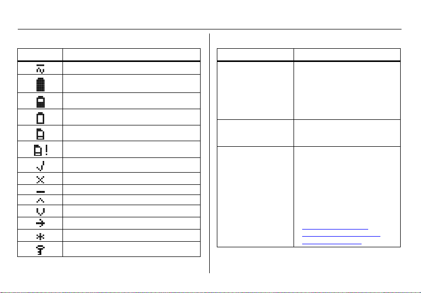
Display Elements Pushbuttons
Item Function
AC power
Batteries fully charged
Batteries half-charged
Batteries at low level
MultiMediaCard (MMC)
MultiMediaCard (MMC) not inserted
Test pass and option enabled
Test fail and option disabled
Cursor and sensor disabled
Scroll up
Scroll down
Selection arrow
Selected to be modified
Passcode protected
2
Pushbutton Description
C
BUMP CHECK
C
CALIBRATION
C
DATA TRANSFER
To bump test a detector, press C
BUMP CHECK.
When connecting a new docking
module, press and hold
C BUMP CHECK to send a
confirmation signal back to the
base station.
To calibrate a detector, press
C CALIBRATION (all models
excluding GasAlertClip Extreme).
To transfer datalog information
from a detector, press C DATA
TRANSFER
Extreme, GasAlertMicroClip, and
GasAlertMax XT only).
The Automatic Datalog Download option is available for the
GasAlertMicroClip and GasAlertMax XT docking modules only.
For more information, refer to
Data Transfer (GasAlert
Extreme, GasAlertMicroClip,
GasAlertMax XT only).
. (GasAlert
Page 5
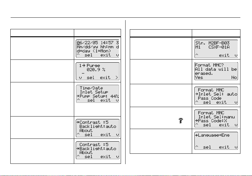
User Options Menu
Description Display
Time/Da te modifies the time and
date of the base station.
Description Display
About
displays the firmware
revision for the base station and
the docking module(s).
MicroDock II
User Options Menu
Inlet Setup enters the gas type,
the gas concentration levels, and
the gas cylinder lot numbers.
Pump Setup
pump speed. Recommended
pump speeds are 40-45% (350
ml/min.). The pump speed must
be set for each new docking module that is added to the station.
NOTE: A flow meter is required.
Contrast brightens or dims the
text of the LCD.
Backlight enables/disables the
LCD backlight. When enabled,
the auto option automatically
deactivates the backlight when
the base station is not in use.
modifies the station
Format MMC formats the Mul-
tiMediaCard (MMC). NOTE:
This feature erases all current
data. Refer to the MicroDock II
User Manual.
Inlet Sel selects a gas inlet. If
auto is displayed, the base sta-
tion automatically selects the
correct inlet for the test.
Pass Code prevents unauthorized access to the menu
options. The LCD displays
when it is pass code protected.
Language displays all LCD
text in one of five languages:
Eng (English), Fran (French),
Deut (German), Port (Portuguese), and Espa (Spanish).
3
Page 6
MicroDock II
Quick Reference Guide
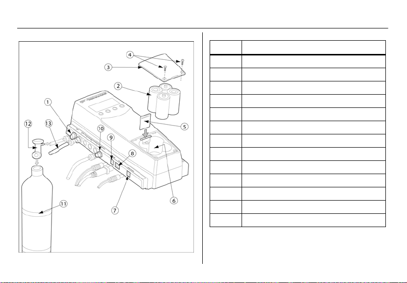
Installation
4
Item Description
1 Inlet filter assembly
2 C-cell batteries (4)
3 Battery cover
4 Philips pan head retaining screws (2)
5 MultiMediaCard (MMC)
6 Battery compartment
7 Charger port
8 USB port
9 Power port
10 Exhaust outlet
11 Gas cylinder
12 Demand flow regulator
13 Calibration gas hose
Page 7

The atmosphere must be free of background gas. Do not
use the base station in a hazardous area.
All required National Electrical Codes (NEC) and safety
standards must be followed.
The base station can operate from either an electrical
power source or batteries. The batteries will provide
automatic backup power if the main power fails.
1. Connect the power cord to the POWER port on the
base station, and then plug the cord into an AC outlet.
To install the batteries, refer to Battery Installation
2. Connect the charger cord to the CHARGER port on
the base station first, and then plug the cord into an
AC outlet.
3. Attach all gas connections. Inlet 1 (PURGE) is configured for ambient air and inlets 2-5 are configured for
calibration/test gases. Refer to Confirm Inlet Setup
4. A demand flow regulator must be used with all gas
cylinder connections.
5. Ensure the exhaust line is not connected to a negative pressure system.
For AC main installation, a circuit breaker must be integrated in the
building installation as a disconnect device for the base station.
a Warni ng
Note
.
.
MicroDock II
Installation
The disconnect device must be installed in close proximity to
the base station and must be marked as a disconnecting
method for the base station.
Battery Installation
To install batteries in the base station, complete the following:
Warn ing
Only install batteries in a safe area that is free of
hazardous gas. Failure to adhere to this warning can
result in personal injury and/or property damage.
Use only BW approved batteries; do not use alkaline or
other rechargeable batteries with this charger.
1. Loosen the retaining screws from the battery cover.
Do not remove the screws from the cover.
2. Remove the battery cover and insert four C-cell batteries into the battery compartment.
3. Replace the battery cover and tighten the retaining
screws. Do not overtighten.
a
Mounting the MicroDock II Base Station and Docking Modules
For wall mounting instructions, refer to the MicroDock II Base
Station User Manual.
5
Page 8

MicroDock II
Quick Reference Guide
Inserting the Detector
Infrared or intense ambient light (sun or halogen) may
interfere with the base station/detector communication.
To insert a detector into a docking module, complete the following:
1. Activate the detector and wait until it is in normal
operation.
2. Ensure the alligator clip is closed and the ring is resting flat on the detector.
3. Press the two release tabs on the docking module
and open the lid.
• If inserting the GasAlertMax XT, move the pump
4. Refer to the following sections to insert the detectors
into the docking modules.
GasAlertClip Extreme / GasAlert Extreme
• Lower the detector (serial number face up) into the
detector bay.
• Push forward to ensure the top of the detector connects
with the top of the bay.
• Close the lid and press until the release tabs click.
• When the detector has been inserted correctly, the RUN
LED(s) on the docking module light yellow and Unit
Inserted displays on the base station LCD. The base
6
a Caution
connector to the open position (red).
station LCD displays the docking module number, and
the type and serial number of the detector.
GasAlertMicro
• Insert the bottom of the detector (serial number face up)
into the detector bay first and then lower the top into
place.
• Close the lid and press until the release tabs click.
• When the detector has been inserted correctly, the RUN
LED(s) on the docking module light yellow and Unit
Inserted displays on the base station LCD. The base
station LCD displays the docking module number, and
the type and serial number of the detector .
GasAlertMicro 5/PID/IR
Important: If the GasAlertMicro 5/PID/IR detector is fitted with
a pump module, the diffusion adapter must be removed from
the docking module. Refer to the MicroDock II Base Station
User Manual.
• Insert the GasAlertMicro 5/PID/IR (LCD facing up) at a
45° angle and insert the bottom into the docking bay.
Ensure the connector outlets on the bottom of the detector lock into place over the connector pins in the docking
bay.
• Close the lid and press until the release tabs click.
Page 9

• When the detector has been inserted correctly, the RUN
LEDs light yellow, Unit Inserted displays on the base
station LCD, and MicroDock displays on the detector
LCD. The base station LCD displays the docking module number, and the type and serial number of the
detector.
GasAlertMicroClip
Important: If the GasAlertMicroClip is fitted with a calibration
cap or an auxiliary filter, it must be removed prior to inserting it
into the docking module. Refer to the GasAlertMicroClip User
Manual and the MicroDock II Base Station User Manual.
• Insert the bottom of the detector (serial number face up)
at a 30° angle into the detector bay.
Note
The docking module lid only raises upward 30°. Do
not force the lid beyond its limit.
• Close the lid and press until the release tabs click.
• When the detector has been inserted correctly, the RUN
LEDs on the docking module light yellow and Unit
Inserted displays on the base station LCD. The base
station LCD displays the docking module number, and
the type and serial number of the detector.
GasAlertMax XT
• Insert the bottom of the detector (serial number face up)
at a 30° angle into the detector bay.
Using the Base Station
MicroDock II
Note
The docking module lid only raises upward 30°. Do
not force the lid beyond its limit.
• Close the lid and press until the release tabs click. Push
the pump connector towards the detector pump.
Ensure green is visible in the lower indicator in the
pump connector. If it is not visible, the MicroDock II base
station will not recognize the detector.
Note
The detector will briefly alarm when the pump
connector is indicated. This is normal. The alarm will
deactivate when the detector is properly inserted into
the docking module.
• When the detector has been inserted correctly, the RUN
LEDs on the docking module light yellow and Unit
Inserted displays on the base station LCD. The base
station LCD displays the docking module number, and
the type and serial number of the detector.
Using the Base Station
To prevent possible personal injury and/or property
damage, only use the station in a safe area that is free of
hazardous gas.
Ensure that the station is attached to a venting system or
used in a well ventilated area.
a Warn ing
7
Page 10

MicroDock II
Quick Reference Guide
The base station pushbuttons are not labelled. The base station
is operated by pressing the C pushbutton that is located
directly below the option that displays on the LCD.
Activating the Station
1. To activate the station, press and hold C (the left-
most button) until the following screen displays.
The normal operation screen then displays.
Deactivating the Station
To deactivate the station, complete the following:
1. Access the normal operation screen (the station can
only deactivate from the normal operation screen).
2. Press C off.
Confirm Inlet Setup
For initial station activation, ensure the inlets are installed correctly.
• Inlet 1—default connection for ambient air.
• Inlet 2—default connection for four-gas mix (unless otherwise specified when purchased).
• Inlets 3-5—designed connection for additional gases.
However, unless specified at purchase, inlets 3-5 will be
configured for ambient air.
Warn ing
Failed bump tests and calibrations can result if the inlets
are not setup correctly.
To confirm that the inlets are set correctly, complete the following:
1. Press C menu to access the user options menu.
2. Press C or to scroll to InletSetup.
3. Press C sel to access the inlet 1 screen.
a
4. Press the C
screens.
to scroll to the inlet 2, 3, 4, and 5
8
Page 11

5. Press C exit to return to normal operation.
For more information on setting up inlets, gas types, and concentration levels, refer to Inlet Setup in the MicroDock II Base
Station User Manual.
Bump Test
A bump test is performed to confirm that the detector is
responding to gas, and that the audio and visual alarms are
operational.
Caution
Ensure the detector is not in a low battery state prior to
performing a bump test.
To perform a bump test, complete the following:
1. From the docking module of the applicable detector,
press C BUMP CHECK.
2. The gas is automatically applied.
a
MicroDock II
Bump Test
The LCD displays the results of the bump test.
If any test fails, refer to Troubleshooting in the
MicroDock II Base Station User Manual.
3. Press C OK to return to normal operation.
4. After 5 minutes of inactivity, the detector deactivates.
For additional information, refer to the MicroDock II
Base Station User Manual.
Calibration (excluding GasAlertClip Extreme)
Warn ing
BW recommends using premium grade calibration gases
and cylinders that are certified to National Standards. The
calibration gases must meet the accuracy of the detector.
All calibration cylinders must be used with demand flow
regulators and must meet the following maximum inlet
pressure specifications
• Disposable cylinders 0-1000 psig/70 bar
• Refillable cylinders 0-3000 psig/207 bar
Ensure the detector is not in a low battery state prior to
performing a calibration.
a
Caution
a
9
Page 12

MicroDock II
Quick Reference Guide
A calibration adjusts the sensor sensitivity to ensure an accurate response to gas.
To calibrate a detector, complete the following:
1. From the docking module of the applicable detector,
press C CALIBRATION.
2. The gas is automatically applied.
3. When the calibration is complete, the system purges.
The countdown for time remaining displays beside
Purge.
= calibration has passed
= calibration has failed
10
If any test fails, refer to Troubleshooting in the
MicroDock II Base Station User Manual.
4. The detector deactivates.
Data Transfer (GasAlert Extreme, GasAlertMicroClip,
GasAlertMax XT only)
This feature transfers datalogs from the detector to the base
station MultiMediaCard (MMC).
To transfer a datalog, complete the following:
1. Activate the detector and insert it into the docking
module.
2. Press C DATA TRANSFER. The RUN LED flashes
rapidly. The base station LCD displays the following
screen:
Depending upon how many logs are stored on the
MMC, the data transfer may require 12-14 minutes to
complete (1-2 minutes for the GasAlertMicroClip and
GasAlertMax XT).
Note
A maximum of ten datalogs from all modules
combined can be stored on an MMC (100 datalogs
for GasAlertMicroClip and GasAlertMax XT).
Page 13

Automatic Datalog Download (GasAlertMicroClip and GasAlertMax XT docking module only)
Successful Data Transfer: The PASS LED lights green on the
docking module and Pass displays on the base station LCD.
From the LCD, press C Pass to return to normal operation.
Unsuccessful Data Transfer: The FAIL LED lights red on the
docking module. Attempt to transfer the data again. If the second data transfer is unsuccessful, ensure the detector is activated. If the problem persists, contact BW Technologies by
Honeywell.
3. To transfer the datalogs to Fleet Manager II, refer to
the Importing Data into Fleet Manager II in the Fleet
Manager II Technical Reference Guide.
4. To view the data that was transferred to the MMC,
refer to Viewing Data in Fleet Manager II in the Fleet
Manager II Technical Reference Guide.
Maximum Storage Capacity
When the maximum storage is reached, the base station
replaces the oldest datalogs with the new datalogs.
Automatic Datalog Download (GasAlertMicroClip
and GasAlertMax XT docking module only)
The Automatic Datalog Download option is enabled/disabled
through Fleet Manager II. If the option is enabled, datalogs are
transferred every time a bump test or calibration is performed.
After performing a bump test or calibration on the GasAlertMicroClip and GasAlertMax XT docking module, the PASS LED
lights green. The DATA TRANSFER RUN LED then lights yellow as the transfer begins.
MicroDock II
Caution
Do not remove the GasAlertMicroClip and GasAlertMax
XT from the docking module until the DATA TRANSFER
PASS LED lights green to indicate the transfer is
complete.
After the data transfer is complete, the detector deactivates
after 5 minutes of inactivity.
For more information about the Automatic Datalog Download
option, refer to the MicroDock II Base Station User Manual.
a
Eventlogging
Bump tests and calibrations are recorded on a
MultiMediaCard (MMC). The MMC is located on the base station in the battery compartment. It stores test records that can
be downloaded from the base station to a PC.
Access Test Results
To access and view test results, refer to Importing Data into
Fleet Manager II and Viewing Data in Fleet Manager II in the
Fleet Manager II Technical Reference Guide.
Configuring the Detector (Not applicable to the
GasAlertClip Extreme)
Use Fleet Manager II to configure the following detectors:
• GasAlert Extreme
• GasAlertMicro
• GasAlertMicro 5/PID/IR
11
Page 14

MicroDock II
Quick Reference Guide
• GasAlertMicroClip
• GasAlertMax XT
The detector can be configured prior to performing a bump test
or calibration to
• change user options,
• sensor options, and
• program options.
The detector can also be configured to disallow bump tests or
calibrations unless performed with the MicroDock II. For more
information, refer to Configuring Detectors in the Fleet Manager
II Technical Reference Guide.
Charging the Battery Pack (Optional)
There is a maximum of six charging docking modules can
be installed on the MicroDock II base station (six charging
modules plus four non-charging modules for a maximum
of ten docking modules per station).
To charge successfully, the temperature must be between
50°F to 95°F (10°C to 35°C). Charge the battery
immediately when the detector emits a low battery alarm.
The charger is for indoor use only.
The detector will not charge while bump tests or
calibrations are being performed. If the battery is low,
12
a Warni ng
Caution
a
Note
charge the detector for 30 minutes, then begin a test.
When the test is complete resume charging the
battery.
When charging a new battery for the first time, ensure the battery obtains a full charge. For more information, refer to the
detector’s user manual or operator’s manual.
Note
Up to six GasAlertMicro and GasAlertMicro 5/PID/IR
detectors can charge simultaneously.
Up to four GasAlertMicroClip and GasAlertMax XT
can charge simultaneously.
For more information, refer to the MicroDock II Base
Station User Manual.
To charge the battery pack, complete the following:
1. Connect the charger adaptor cord into the CHARGE
port on the station, and then plug into an AC outlet.
The CHARGE LED briefly lights red then green during the self-test. The LED then powers off (not applicable to the GasAlertMicroClip and GasAlertMax XT
modules).
2. Deactivate the detector. Insert the detector into the
charging cradle.
3. The CHARGE LED lights red (all charging modules).
Page 15

4. Allow the battery to obtain a full charge (2 to 4 hours,
depending upon how many docking modules are connected to this station).
If a docking module is in queue waiting to charge, the
CHARGE LED flashes red (all charging modules).
When the docking module begins charging, the
CHARGE LED stops flashing and lights solid red.
The CHARGE LED lights green when the charging
process is complete. If there are other docking modules in queue, waiting to charge, they will begin
charging.
The CHARGE LED deactivates when the detector is
removed.
MicroDock II
Maintenance
Maintenance
No user-serviceable parts inside.
Confirm that the inlet filter is free of dirt and replace if
required. To order replacement parts, refer to
Replacement Parts and Accessories in the MicroDock II
Base Station User Manual.
To maintain the station in good operating condition, perform the
following basic maintenance as required.
• Clean the exterior with a soft, damp cloth. Do not use solvents, soaps, or polishes.
• Do not immerse the station in liquids.
a Warn ing
a
Caution
13
Page 16

MicroDock II
Quick Reference Guide
Specifications
The MicroDock II base station and docking modules are for
indoor use only.
Instrument dimensions: (w x l x h) 21.2 x 26.3 x 8.2 cm
(8.3 x 10.4 x 3.2 in.) base station and one docking module
Weight: 0.98 kg (2.15 lb.)
Base system ingress protection: IP20
Operating temperature: +10°C to +35°C (+50°F to +95°F)
Humidity: 0 to 50%
Altitude: 2000 m (6561.66 ft.)
Storage temperature: -10°C to +60°C (+14°F to +140°F)
Power supply: 6 Vdc , 1.5 A wall adapter or four C-cell
batteries (be advised that the main supply voltage fluctuations
are not to exceed 10% of the nominal supply)
Pollution Degree: 2
Installation Category: I
Real-time clock: Provides time and date stamp
Data storage: Automatic (instrument and base station)
128 MB Delkin MMC data storage system
External interface: USB interface for PC
Pump: DC motor, micro-diaphragm, 3V PCB mount
Flow rate: Maximum recommended 350 ml/min.
Calibration gas cylinder inputs:
• 2-gas inlets (standard)
• 4-gas + air inlets (maximum)
Automatic tests: Functional bump, calibration, audible alarm,
visual alarm
14
Configuration recognition: Automatic (instrument and sensor)
Alarm/calibration parameters: User defined
Calibration gas connections: Built-in (base station)
Gas connection: 1/8” SMC connect sub-miniature coupling
Solenoid: Built-in (docking modules)
LED indicators: (on each docking module)
Yellow - Test
Green - Pass
Red - Fail
Command keys:
Base station: Menu navigation
Docking module: One touch bump-test initiation
One touch calibration initiation: not applicable to the
GasAlertClip Extreme
One touch data transfer initiation: GasAlert Extreme,
GasAlertMicroClip, and GasAlertMax XT only
Communications method: Infrared (two-way)—between
docking module and detector (not applicable to the GasAlertClip Extreme—one way communication only).
USB port for connection to a:
• Personal computer (PC), or
• USB over IP HUB
Sensors: Audio and optical
LCD: 4 line x 16 characters, wide viewing angle, user-defined
backlighting
Enclosure: Impact resistant PC/ABS (polycarbonate)
Warranty: 2 years
Page 17

Charger Specifications
Size: 8.6 x 8.2 x 7.8 cm (3.4 x 3.2 x 3.1 in.)
Weight: 97 g (3.4 oz.) per model
Charger system ingress protection: IP20
Operating temperature: 10°C to 35°C (50°F to 95°F)
Humidity: 0 to 50%
Altitude: 2000 m (6561.66 ft.)
Power: 6 Vdc , 2.5 A
Charging LED: Color-coded LED indicates charging, charge
complete, and charger fault
Charge time: Typically 2-6 hours
Pollution Degree: 2
Installation Category: I
This device complies with the FCC Part 15 and ICES-003
Canadian EMI requirements. Operation is subject to the following two conditions:
1. This device may not cause harmful interference, and
2. this device must accept any interference received,
including interference that may cause undesired
operation.
This equipment has been tested and found to comply with the
limits for a Class A digital device, pursuant to Part 15 of the
FCC Rules and ICES-003 Canadian EMI requirements.
These limits are designed to provide reasonable protection
against harmful interference when the equipment is operated in
a commercial environment.
Charger Specifications
MicroDock II
This equipment generates, uses, and can radiate radio frequency energy and, if not installed and used in accordance with
the instruction manual, may cause harmful interference to radio
communications.
Operation of this equipment in a residential area is likely to
cause harmful interference in which case the user will be
required to correct the interference at his/her own expense.
Warn ing
This product is designed for installation in an indoor
location only. All required National Electrical Codes and
Safety Standards must be followed.
For ac main installation, a circuit breaker should be
included in the building installation as a disconnect
device for the equipment. The disconnect device should
be installed in close proximity to the equipment and the
device should be marked as a disconnecting means for
the equipment.
a
15
Page 18

MicroDock II
Quick Reference Guide
16
Page 19

iERP: 126102
D5618/7 [English]
© BW Technologies 2008. All rights reserved.
 Loading...