

Page 1
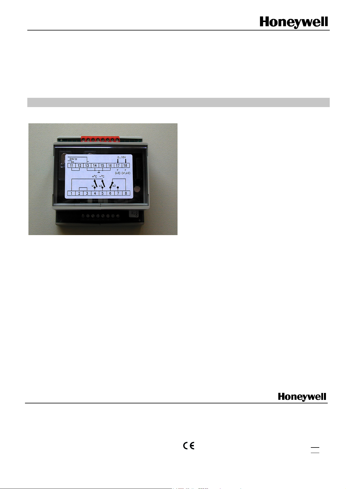
MCD 3
External Output Relay Module
Two Digital and One Floating Output
PRODUCT DATA
Technical data
Input Circuit
Nominal voltage / power
consumption 24 V AC/DC 13 mA
Nominal voltage tolerance ± 10%
Switch protection input varistor
Operational display LED
Energize / de-energize time 10 ms / 5 ms
Output circuit
Output contact K1, K2 1 normally open relay, SPST
Output contact K3 1 change-over relay, SPDT
Contact material AgCdO
Switching voltage max. 240V AC/DC
Switching current K1, K2 1.2A/24 VAC, 0.2A/240 VAC
Switching current K3 2A/240 VAC
Breaking capacity max.
(resistive load)
Minimum switching capacity 24 V DC / 20 mA
Mechanical loading 2 x 10
Electrical loading 10
Switching frequency max. 600 switching operations per
General data
Insulation as per VDE
0110/01.89
Test voltage coil / contact 2 kV 50 Hz 1 min.
Protection as per DIN
40050
Permissible ambient
temperature
Wire size 2.5 mm²
Mounting position optional
Weight approx. 0.045 kg
24 V DC / 150 W
50 V DC / 25 W
230 V DC / 50 W
230 V AC / 1500 VA
7
switching operations
5
switching operations at
max. load
hour at max. current
rated voltage 250 V
overvoltage category III
pollution level 3
housing IP 50,
terminals IP 20
- 20 ... + 55° C
Home and Building Control
Honeywell AG
Böblinger Strasse 17
D-71101 Schönaich
Phone: (49-70 31) 637- 01
Fax: (49-70 31) 637- 493
Subject to change without notice. Printed in Germany
EN0B-0348 GE51R0101
Manufacturing location is certified according to
DIN
ISO 9001
Page 2
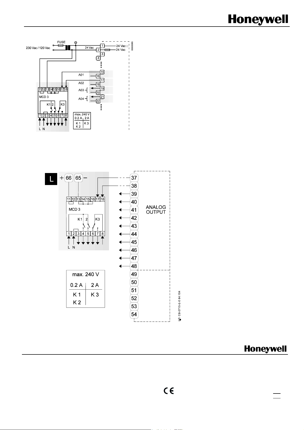
Wiring example when used with XL50:
Relay terminal 17 controls the change-over contact K3.
Relay terminal 18 controls the ON contacts K1, K2.
Ground can be looped through terminals 2/3.
Wiring example when used with
XL100C:
The relay modules are supplied via the
special relay connection of the controller
(terminals 65/66)
IMPORTANT
Important during connection:
1. Correct polarity
2. Under no circumstances may
a relay module be connected to the
reference voltage.
Several relay modules can be connected
in series via the bridged terminal pair:
Plus pole: Terminals 11/12 of the relay
Minus pole: Terminals 13 to 16 of the relay
L (Fig. left)
Terminal 17 controls the changeover
contact K3. Terminal 18 controls the
ON contacts K1, K2. Ground can be
looped through terminals 2/3.
Home and Building Control
Honeywell AG
Böblinger Strasse 17
D-71101 Schönaich
Phone: xx49 - (0)70 31 - 637- 01
Fax: xx49 – (0)70 31 - 637- 493
Subject to change without notice. Printed in Germany
EN0B-0348 GE51R0101
Manufacturing location is certified according to
DIN
ISO 9001
 Loading...