

Page 1
MAXPRO® NVR XE
Chassis feet
Not shown:
MAXPRO NVR DDNS Installation Instructions
Recovery USB Flash Drive
MAXPRO NVR Client Software
(Single Site) and Server Software
DVD (includes manuals)
MAXPRO Viewer Multi-Site Viewing
Software Kit (includes DVD and
Getting Started Guide). Not shown.
Note Other peripheral hardware (owner supplied) will also be needed for your installation
(such as cameras, network PoE switch for the camera network, network switch for a
client workstation network, a monitor, and an optional keyboard controller).
Connect supplied keyboard
and mouse before powering
up the NVR.
Connect up to 16 IP cameras to
a camera network PoE switch
and the switch to the LAN1
camera network port.
Connect a local monitor
to one of the monitor
outputs.
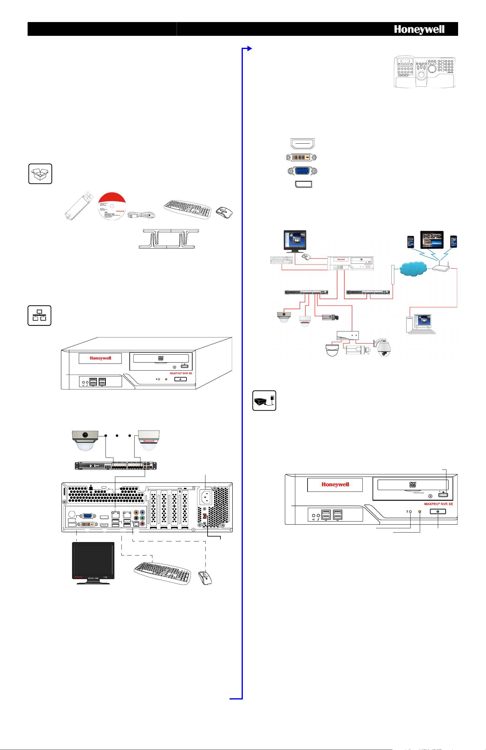
# Connector Connects to...
1 VGA Port VGA monitor
2 Display Port DP monitor
3 LAN1 - Camera Network Port Network
4 LAN2 - Client/Workstation Network Port Network
5 DVI-D Port DVI monitor
6 HDMI Port HDMI monitor
7 USB Ports (x4) Various devices
8 S/PDIF (Optical) Not used
9-13 Audio inputs and outputs Not used
14 AC Power Electrical outlet
Connect power cord
3
5
14
4
8
9-13
2
1
6
7
Power
preference
switch (to
switch
between
115 V and
230 V inputs)
Local Monitor (not supplied)
Mobile Devices
MAXPRO® NVR XE
Router/
Firewall
Wireless
Router
Network
Client Workstation
Camera Network PoE Switch
Client Workstation Network Switch
Honeywell and Third-Party
IP Cameras
Encoder
H4D2F1
HD4HDIH
H3D2F1
HD3HDIH
HCD2F
HCD5HIH
Camera Network Port
(default 192.168.1.101)
Client Workstation Network
Port (default 172.25.254.101)
Analog Cameras
CAT5e
CAT5e
CAT5e
CAT5e
CAT5e
CAT5e
CAT5e
CAT5e
USB
USB
VGA/DVI-D/HDMI/DP
Power button with
Power LED (blue)
HDD activity
(Will flash amber when the
drive is in use)
Reset switch
Open CD/DVD-ROM
drive tray
(Xpress Edition)—Rev B
Entry Level Network Video Recorder
Quick Install Guide
Document 800-16129V4 – Rev A – 03/2017
Introduction
Welcome to your new Honeywell MAXPRO® NVR XE. This guide helps you set up the NVR right
out of the box. Before installing your NVR, please read this guide carefully.
Note Translated Quick Install Guides can be accessed on your MAXPRO NVR unit after logging
in, by clicking on Start menu
Honeywell Quick Install Guides.
Rear Panel Connections
Keyboard Controller (Optional) Follow the
documentation that was included with your IP keyboard
controller to connect it to the NVR.
Network Connections Connect a network PoE switch to th e camera network port at the rear of the
MAXPRO NVR. Connect your cameras to the network PoE switch with CAT5 Ethernet cables.
Optionally, connect the client workstation network port to your client workstation network via a
network switch. This allows remote access to your NVR. The default client workstation network IP
address must be changed to an available static IP address on your client workstation network.
Monitor(s) The MAXPRO NVR XE comes wit h built -in graphics and fou r types of monitor outputs.
The unit supports connection of a single monitor using one of the outputs.
HDMI Output to HDMI monitor
DVI-D Output to DVI monitor
Unpack
Check that the items received match those listed on the order form and packing slip. The packing
box should include, in addition to your NVR unit and this guide:
Install the Hardware
Mount the MAXPRO NVR XE Unit Mount the MAXPRO NVR XE unit on a flat surface, horizontally
or vertically, using the supplied chassis feet.
VGA Output to VGA monitor
Display Output to DP monitor
The recommended resolution for your monitor is 1280 x 1024 pixels (minimum 1024 x 768) and
display colors of at least 32 bit.
Dual Network Configuration
Connect the Hardware
Rear Panel
Contact your dealer to purchase Honeywell and third-party IP and analog cameras and encoder.
Power Up the Unit
Note Honeywell recommends using an uninterruptible power supply (UPS) for the NVR unit, the
camera network switch, and the cameras to ensure that the NVR can continue to record
video during a power outage or during transient power events. If you need to monitor
video during a power outage, consider a UPS for the monitor as well.
1. Before powering up the NVR, turn on camera(s) and other devices — such as a network
switch or router — connected to the NVR.
2. Press the power button on the front of the NVR.
Front Panel LEDs
www.honeywell.com/securit y 800-16129V4 – Rev A – 03/2017
Switching the Power Preference
The MAXPRO NVR XE power rating is 115V/230V AC, 7/4 A, 60/50 Hz, 300 W.
The recommended power input is 110-120 V.
In some regions users may require the use of a 230 V AC power input. In this case, flip the power
input preference switch on the back of the MAXPRO NVR XE unit (see the diagram of the back panel
above for the location of the switch).
3. After powering on the unit, you are prompted to log on. The Default user is user name:
NVR-Admin, password: Password$123. The user name and password are case sensitive.
You will be prompted to create a new password the first time that you log in.
The setup wizard starts automatically but may take two minutes.
Note Translated Quick Install Guides can be accessed on your MAXPRO NVR unit after logging
in, by clicking on Start menu
Honeywell Quick Install Guides.
Page 2
2 | MAXPRO® NVR XE Quick Install Guide
MAXPRO® VIEWER
Multi-site Viewing Software
Honeywell Confidential
& Proprietary
HNMVIEWER
Software
Copyright 2013
Honeywell International Inc.
All rightsreserved.
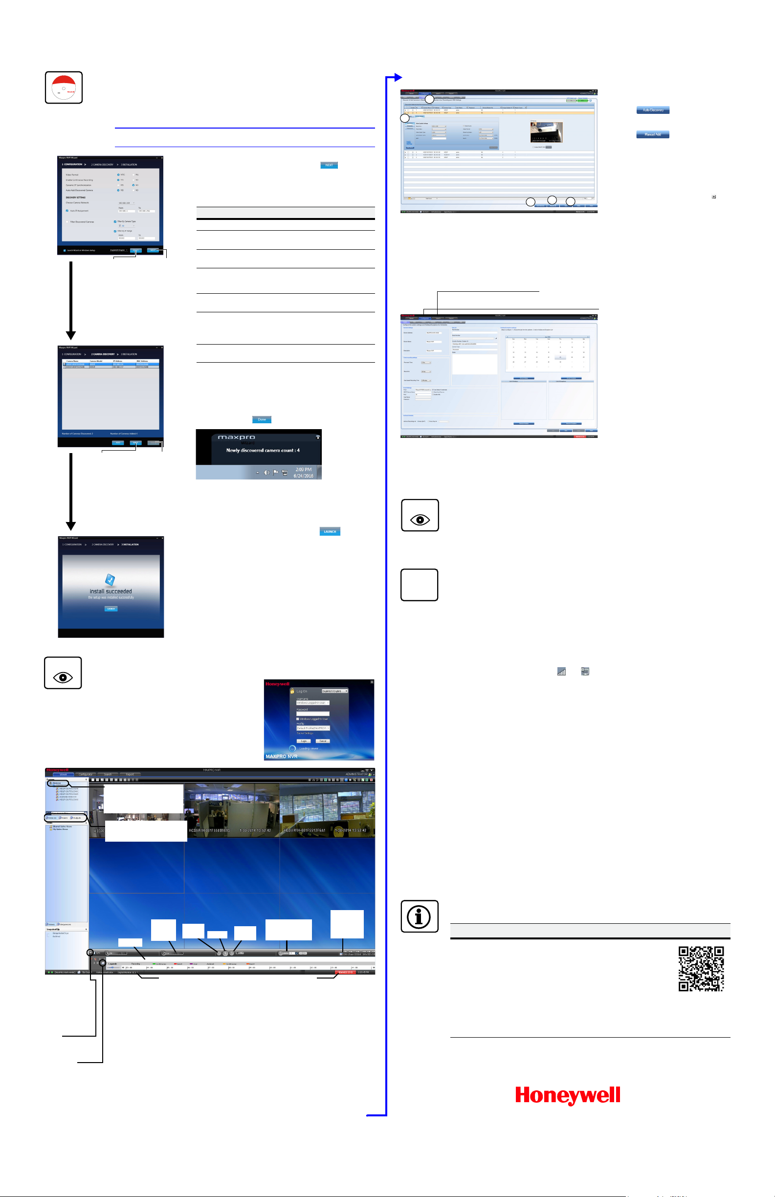
1. The CONFIGURATION dialog appears. When the network is
ready (network icon in Windows tray), click to accept
the default settings and proceed to CAMERA DISCOVERY.
To modify the settings for your unique system requirements,
follow the table below. After initial setup, you can do this in the
MAXPRO NVR client.
2. The CAMERA DISCOVERY window appears.
Each newly connected camera is identified and an IP address
is assigned to the camera by the Wizard, after which the
camera reboots. It may take a few minutes before cameras are
discovered and added. You will see a Discovery in progress…
indicator as well as a pop-up message on the lower right of
your monitor. Click .
3. The INSTALLATION window appears. Click to start the
MAXPRO NVR application. Proceed to Live View.
4. Only Honeywell IP cameras and HVE encoders (except
Honeywell Performance Series and New equIP
®
Series IP
cameras) are discovered and added in the MAXPRO NVR
Wizard.
* 3 clicks for specific models with default settings and in a local area
network.
Field Description
Video Format NTSC, PAL
Enable Continuous
Recording
Start recording as soon as the camera is
added in MAXPRO NVR.
Dynamic IP
Synchronization
NVR synchronizes any change in a
device’s IP address.
Auto Add
Discovered
Cameras
Any newly connected device is
automatically added to the Devices list.
Choose Camera
Network
Choose your camera network.
Auto IP Assignment Assigns a valid static IP address to the
camera. Use only if you do not have a
DHCP server and you want to assign an IP
address in your computer network range.
Filter Discovered
Cameras
Filter the discovered cameras based on
the camera model and/or IP range.
Return to
CONFIGURATION
page.
Click only
after all
connected
cameras are
discovered
and added.
Reset values
without saving
changes.
Proceed to
CAMERA
DISCOVERY.
WATCH
User currently logged
on
Number of alarms
detected
List of Honeywell IP devices
and analog cameras
connected to and discovered
by MAXPRO NVR.
Timeline
Change
playing
speed
Play in
reverse
Pause
Play
forward
Select date
and time
to start
recording
Time jump
control to quickly
locate video
Images/Clips:
select images and
clips to view.
Double-click or
drag the clip to a
Viewer panel to
view.
To export a clip for
forensics, click the
arrow
to switch to Full
Timeline mode,
then click the Clip
Export icon.
Devices tab: currently active.
Alarms tab: acknowledge and
clear alarms.
1. On the Configurator tab, click the
Camera tab.
2. Click (Auto Discovery) to
automatically discover the connected
IP cameras in the subnet.
3. Click (Manual Add) to
manually add the IP device to the
Camera list. Enter the device’s IP
address into the field and ensure that
the user name and password listed for
the new camera match the user name
and password of that camera.
4. To change the default parameters of a
camera, select it and then click at
the beginning of the camera line to
open the camera advanced settings
pane where you can modify the
settings as required.
5. Click Save for your new settings to
take effect.
2
1
4
5
3
Use the Search tab to search for recorded video (clips) or events.
Use the Configurator tab to configure video
devices and set up your MAXPRO NVR
system.
Configurator tab sub-tabs:
System: System information, event
recording, email, archival schedule,
holiday/exceptions for schedules.
Disk: Configure and monitor video
storage hard drives.
Camera: Discover and add network
cameras, live camera configuration,
recording, video motion detection.
Schedule: Set recording schedules
configuration.
I/O: Configure input and output for
each camera.
Sequence: Select a sequence of
cameras for live video.
User: Set user access and permission
levels.
WATCH
IP
Honeywell IP Camera Configuration
Using the MAXPRO NVR Wizard (3 Clicks* to Live Video)
Note The setup wizard starts automatically but may take two minutes.
Third Party Device Configuration
Additional Configuration
Live View
1. Please wait while the system logs you on
automatically as a Windows Logged-In User.
2. MAXPRO NVR launches and the Viewer tab
displays (see below).
3. To view video from cameras, drag MAXPRO NVR
© 2017 Honeywell International Inc. All rights reserved. No part of this publication may be reproduced by any means without
written permission from Honeywell. The information in this publication is believed to be accurate in all respects. However,
Honeywell cannot assume responsibility for any consequences resulting from the use thereof. The information contained herein
is subject to change without notice. Revisions or new editions to this publication may be issued to incorporate such changes.
For patent information, see www.honeywell.com/patents.
in the Devices list into the display panel to show
video from all discovered cameras in the Viewer.
You can also highlight and drag each camera into
a panel.
MAXPRO NVR Web Client
To access the Web Client, click on the MAXPRO NVR Web Client shortcut on the NVR desktop. Clic k
Continue on the self signed certificate warning message that appears. Login to the Web Client with
default Username: admin and Password: trinity.
MAXPRO NVR XE Default IP Address Configuration
Your MAXPRO NVR XE unit has two configured network ports with the following default static IP
addresses:
• 192.168.1.101 for LAN1 (Camera Network)
• 172.25.254.101 for LAN2 (Client Workstation Network)
If more than one MAXPRO NVR XE unit is on the same network, you must assign a unique IP address
and computer name to each unit (the default name is MAXPRO-NVR).
1. To change the IP address using Windows:
a. Click the network icon ( ) or ( ) located next to the clock (lower right of screen),
click Open Network and Sharing Center, then click Change adapter settings.
b. Right-click Camera Network or Client Workstation Network, and then select
Properties.
c. Click Internet Protocol Version 4 (TCP/IPv4), then click Properties.
d. Click Use the following IP address, then in the IP address, Subnet mask, and
Default gateway boxes, type the IP address settings.
e. Click Use the following DNS server addresses, and then, in the Preferred DNS
server and Alternate DNS server boxes, type of the addresses of the primary and
secondary DNS servers. This step is required when clients connect through the
Internet.
2. To change the computer name using Windows:
a. Click Start, right-click Computer, click Properties, click Advanced system settings,
click the Computer Name tab, and then click Change.
b. Under Computer name, delete the old computer name, type a new computer name,
and then click OK. The name cannot contain spaces or all numbers or any of the
following characters: < > ; : " * + = \ | ?.
c. After changing the computer name, restart the computer.
d. Navigate to the C:\Program Files(x86)\Honeywell\MaxproNVR\TrinityFramework\bin
folder, and then double-click MaxproNVRMachineNameUtility.exe to open the
MAXPRO NVR Utility.
e. The new computer name should automatically appear in the Machine Name field. If it
does not, enter the name manually. Click Update. The message Machine Name
Updated successfully appears when the update is complete.
More Information
MAXPRO NVR XE Third Party Devices
Please refer to the appropriate user
guide located on the software/
documentation DVD or on the
Honeywell product web site at
www.honeywell.com/security.
The MAXPRO NVR Guides
(Installation and Configuration Guide,
and Operator’s Guide) provide
detailed information on adding and
configuring third party cameras, the
multi-function Web Client, as well as
other advanced features.
www.honeywell.com/security
+1 800 323 4576 (North America only)
https//honeywellsystems.com/ss/techsupp/index.html
Document 800-16129V4 – Rev A – 03/2017
A comprehensive list of all the third
party devices supported by MAXPRO
NVR XE is available on the product
compatibility page:
www.security.honeywell.com/hota/
compatibility/index.html.
www.honeywell.com/security/uk
+44 (0) 1928 754 028 (Europe only)
https//honeywellsystems.com/ss/techsupp/index.html
 Loading...