

Honeywell MAXPRO NVR PE Quick Installation Manual
Document 800-12139 – Rev A – 06/2012
MAXPRO® NVR PE Quick Installation Guide
See over for configuration steps.
Overview
This document covers how to:
• Connect essential hardware to a MAXPRO NVR PE unit.
• Configure network settings, set up IP addresses, and discover connected devices.
• Configure a MAXPRO NVR PE unit to record video.
Note More detailed MAXPRO NVR PE documentation is available on the software and documentation DVD
included with your unit.
1. Before You Begin
The following items come with your MAXPRO NVR PE chassis and may be needed for installation and setup:
Note Other peripheral hardware (owner supplied) will also be needed for your installation, such as cameras,
network equipment, and an optional keyboard controller. See 2. Installing Unit for more information.
2. Installing Unit
Components of a MAXPRO NVR PE System
Your system may include some or all of the following components:
• Hard drives for video storage
• Video cameras and/or PTZ dome cameras (owner supplied)
• VGA monitor (owner supplied)
• Keyboard controller (owner supplied)
• Computer keyboard (included)
• Computer mouse (included)
• Rail hardware kit for rack mount installations (included)
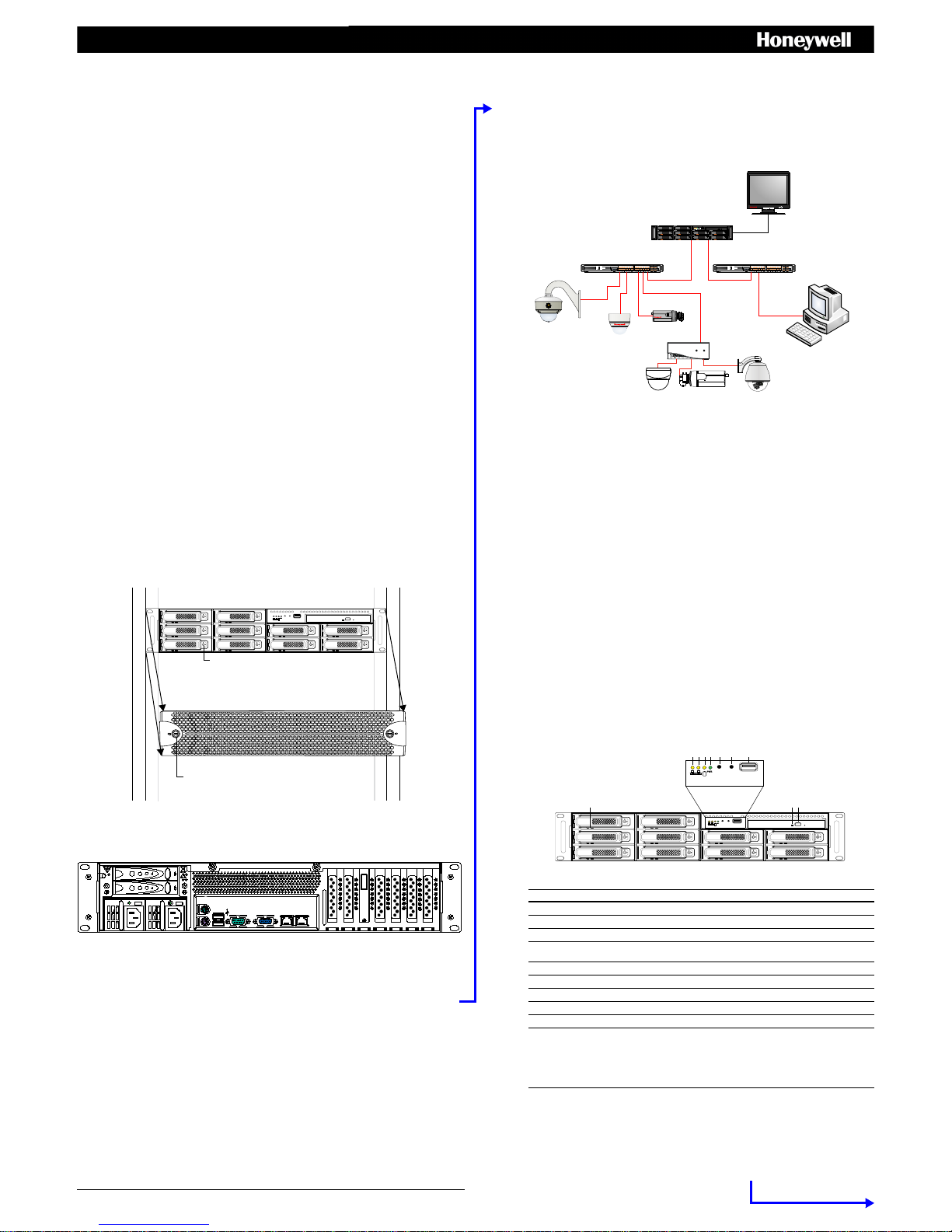
Mounting the MAXPRO NVR Unit in a Rack and Installing Hard Drives
1. Remove the bezel from the front of the unit. To remove the bezel, turn the two bezel key locks clockwise, and then
pull the bezel away from the unit.
2. The MAXPRO NVR PE unit should be mounted with the supplied rail hardware kit. The kit allows the MAXPRO NVR
PE unit to slide in and out of the rack it is mounted in and provides rear support for the chassis. Refer to the
installation instructions included with the rail hardware kit.
3. Install the supplied video storage hard drives in the hard drive slots located on the front of the unit. The drives are
numbered from 1 to 10, from the top left to the bottom right.
Note
The video storage hard drives are pre-configured for RAID 5 in the factory but can be reconfigured f or RAID 6
if required, however there will be less usable video storage space.
4. Replace the bezel on the front of the unit. To replace the bezel, align the bezel key locks with the handles on the
front plate of the unit, and then slide the bezel into place. Turn the bezel key locks counterclockwise to secure the
bezel.
3. Connecting Hardware
Rear Panel Connections
•Power cord
• Keyboard (PS/2)
•Mouse (PS/2)
•This guide
• Video storage hard drives
• Recovery DVD
• Rail hardware kit with instructions for rack mount installations
• MAXPRO NVR Software and Documentation for Server and
Client Installation DVD
• MAXPRO Viewer Multi-Site Viewing Software Kit
(includes DVD and Quick Install Guide)
Bezel key lock (×2)
Hard drive release button.
# Connector Connects to...
1 DIN-8 Connector PC PS/2 mouse
2 DIN-8 Connector PC PS/2 keyboard
3 USB Port Various devices
4 USB Port Various devices
5 COM1 Port
6 DB-15 VGA Connector Monitor
7 Gigabit LAN 1- Camera Network Port Network *
8 Gigabit LAN 2 - Client Network Port Network *
11
2
# Connector Connects to...
9-10 Blank N/A
11 SAS Connector N/A
12-15 Blank N/A
16 AC Power Connector AC power
17 AC Power Connector AC power
3
1
10 12 13 14 15
* Network connectors have two LEDs:
• Link LED (left) indicates the connection speed (yellow = 1 Gbps, green = 100 Mbps).
• Activity LED (right) flashes yellow when active.
16 17
9
5 6 7 8
4
Cameras
Connect a network switch to the Gigabit LAN 1 connector (camera network port) at the rear of the MAXPRO NVR PE
unit. Connect your cameras to the network switch with CAT5 Ethernet cables. The Gigabit LAN 2 (client network port)
can be used to connect remote client workstations on a separate network, isolating the load on the camera port.
Monitor(s)
Connect a VGA monitor. The recommended settings for your monitor are 1280 × 1024 pixels (resolution), and 65K
colors non-interlaced (color quality). Refer to the MAXPRO® NVR Commissioning and Installation Guide for more
information on configuring the monitor display properties. The local VGA monitor can be used to configure the NVR,
however continuous local video monitoring is not recommended.
Keyboard and Mouse
Before powering up the MAXPRO NVR PE, connect the supplied PS/2 keyboard and mouse to the DIN-8 connectors at
the rear of the unit.
Keyboard Controller
Follow the documentation that was included with your keyboard controller to connect it to the MAXPRO NVR PE unit
through the network.
4. Powering On the Unit
Note Honeywell recommends using an uninterruptible power supply (UPS) for the MAXPRO NVR PE unit,
camera network switch, and the cameras. Powering the cameras, network switch, and unit from a UPS
ensures that the MAXPRO NVR PE unit can continue to record video during a power outage. If you need to
monitor video during a power outage, consider a UPS for the client workstation and client network switch
as well.
MAXPRO NVR PE Power On Sequence
1. Turn on the camera(s) and other hardware connected to the MAXPRO NVR PE unit.
Note Honeywell recommends turning on the cameras before turning on the MAXPRO NVR PE unit since IP
cameras can take up to two minutes to boot up. Online cameras can be easily discovered by the unit after
startup. It is also recommended to turn on other associated network components, such as a network switch
or router, before turning on the MAXPRO NVR PE.
2. Press the power button on the front of the MAXPRO NVR PE unit (the power button is labelled 6 in the image
below).
3. After powering on the unit, you are prompted to log on. The default user is user name: Administrator, password:
Password1. The user name and password are case sensitive.
Front Panel
ClientWorkstation
Local Monitor
CAT5e
CAT5e
Client Network SwitchCamera Network Switch
MAXPRO NVR PE
CAT5e
CAT5e
CAT5e
CAT5e
CAT5e
HD4HDIH
Encoder
Analog Cameras
HD3HDIH
HCD5HIH
Honeywell andThird-Party
IP Cameras and Encoders
1234 5 6 7
8910
No. LEDs, Buttons, Ports Color Behavior
1 NIC2 LED (Client Port) Yellow On = There is client network activity.
2 NIC1 LED (Camera Port) Yellow On = There is camera network activity.
3 HDD LED Yellow On = There is OS hard drive activity.
4 Power LED Green On = The system is powered on.
Off = The system is powered off.
5 Reset button Black Resets the unit.
6 Power button Black Powers on the unit.
7 USB port — Receives a USB device.
8 DVD Drive LED Green On = There is DVD activity.
9 DVD Drive button Black Opens the DVD tray.
10 HDD Activity/Ready LED
HDD Failure LED
Blue
Red
On = Hard drive is inserted and detected.
Flashing = System is accessing the hard drive.
Off = Hard drive is not detected.
On = The hard drive is detected as a failure by the host.
Flashing = RAID rebuilding.
Off = There is no hard drive, or the hard drive is operating normally.
www.honeywellvideo.com
+1.800.796.CCTV (North America only)
HVSsupport@honeywell.com
Document 800-12139 – Rev A – 06/2012
MAXPRO® NVR PE Quick Installation Guide
© 2012 Honeywell International Inc. All rights reserved. No part of this publication may be reproduced by any means without written
permission from Honeywell. The information in this publication is believed to be accurate in all respects. However, Honeywell cannot
assume responsibility for any consequences resulting from the use thereof. The information contained herein is subject to change
without notice. Revisions or new editions to this publication may be issued to incorporate such changes.
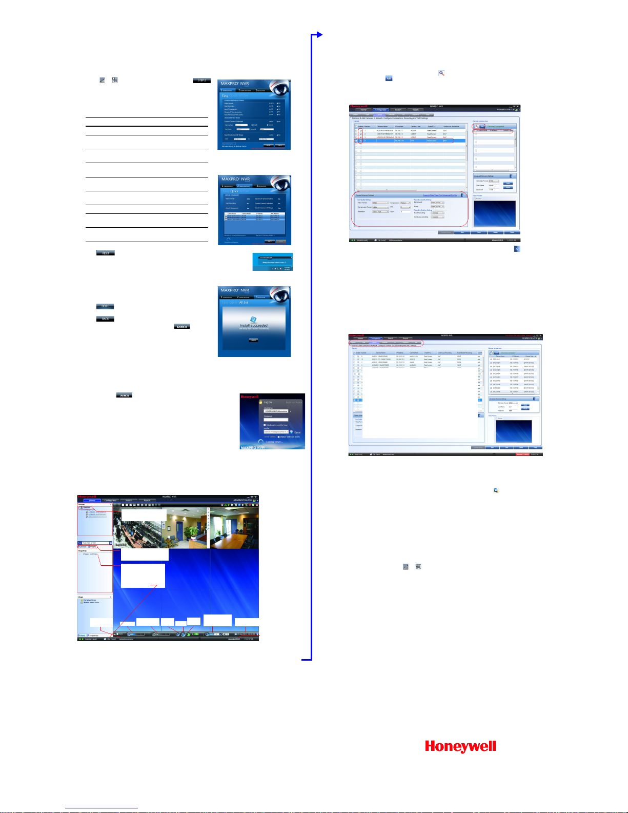
5. Honeywell IP Camera Configuration
Using the MAXPRO NVR Wizard (3 Clicks to Live Video)
The setup wizard starts automatically after you log on (this can take up
to two minutes).
1. The CONFIGURATION page is displayed. When the network is
ready ( or appears in the notification area), click
to accept the default settings and proceed to CAMERA
DISCOVERY.
To modify the settings for your unique system requirements, refer
to the table below. (After initial setup, you can do this in the
MAXPRO NVR client.)
Click to reset the values without saving any changes.
2. The CAMERA DISCOVERY page is displayed. Each newly
connected camera is identified and an IP address is assigned to
the camera by the Wizard, after which the camera reboots.
It may take a few minutes before the cameras are discovered and
added. You will see a
Discovery in progress… indicator in
addition to a pop-up message on the lower right of your monitor.
The list disappears as the cameras are added to the MAXPRO
NVR.
Click only after all connected cameras are discovered
and added.
Click to return to the CONFIGURATION page.
3. The INSTALLATION page is displayed. Click
to start the
MAXPRO NVR application (see 3 Live View).
Note To add non-Honeywell devices, see 7. Third-Party Device
Configuration.
6. Live View
Log On to the MAXPRO NVR Viewer
1. When you click in the Setup Wizard, the Log On dialog box appears.
Please wait while the system logs you on automatically as a Windows LoggedIn User.
2. MAXPRO NVR launches and the Viewer tab appears (see below). The
Devices area in the left pane lists all of the discovered network cameras.
View Live Video
To view video from cameras, double-click MAXPRO NVR in the Devices list to
display video from all discovered cameras in the Viewer. You can also highlight
and drag each camera into a panel.
Note For continuous monitoring of live video, it is recommended that you use a remote client workstation.
You can install a remote client using the installation software contained on the software and documentation
DVD included with your unit. Select Client Installation as the Installation Type during setup. For more
details, refer to the MAXPRO
®
NVR Commissioning and Installation Guide.
Field Description
Video Format NTSC, PAL
Start Recording Start recording as soon as the camera
is added in MAXPRO NVR.
Auto IP Assignment Software assigns IP address
automatically.
Dynamic IP
Synchronization
Software synchronizes any change in
a device’s IP address.
Auto Add
Discovered Camera
Any newly connected device is
automatically added to the device list.
Custom Camera
Credentials
Not configurable in the Wizard.
Camera Type Not configurable in the Wizard.
Username,
Password
Not configurable in the Wizard.
Camera IP Range The system automatically detects all
cameras in this range on the network.
STEP 1: CONFIGURATION
STEP 2: CAMERA DISCOVERY
STEP 3: INSTALLATION
Pop-up
message
List of Honeywell IP cameras
connected to and discovered
by MAXPRO NVR.
Devices tab: Currently active.
Alarms tab: Acknowledge and
clear alarms.
Images/Clips: Select images
and clips to view.
Double-click or drag the clip
to a Viewer panel to view.
To export a clip for forensics,
click Clip Export.
Number of alarms detected
Timeline
User currently
logged on
Change
playing speed
Play in
reverse
Pause
Play
forward
Select date and time
to start recording
Time jump control
to quickly locate
video
7. Third-Party Device Configuration
Non-Honeywell devices are configured using the MAXPRO NVR software. To set up cameras for video input:
1. Launch MAXPRO NVR.
2. On the Configurator tab, click the Camera tab.
3. In the Discover cameras here area, click to discover the connected cameras in the subnet,
and then click to add a camera to the Camera list.
4.
In the
Camera
list, ensure that the
Enable
check box is selected for the camera(s) that you have added and that the
user name and password that appears on the screen matches the user name and password of the camera. The user
names and passwords must match for the MAXPRO NVR PE unit to connect and stream video
.
5. To change the default parameters of a camera, select the camera, and then click next to Advanced
Discovery Settings to open an advanced settings pane where you can modify the settings as required.
6. Click Save for your new settings to take effect.
8. Advanced Features
Note For more detailed information on the advanced features available in MAXPRO NVR PE, please refer to the
comprehensive guides available in the UserManuals folder on the software and documentation DVD.
Configurator Tab
Use the Configurator tab to configure video devices and set up your MAXPRO NVR PE system. The Configurator tab
consists of seven sub-tabs: System, Disk, Camera, Schedule, I/O, Sequence, User.
Search Tab
Use the Search tab to search for recorded video (clips) or events.
1. Select the check box next to the camera(s) from which the video was recorded.
2. Select search conditions in the Date time filter, and then click Search ().
9. MAXPRO NVR PE Default IP Addresses
Your MAXPRO NVR PE unit has two configured network ports with the following default IP addresses:
• 192.168.1.101 for NIC1 (Camera Network)
• 172.25.254.101 for NIC2 (Client Workstation Network)
If more than one MAXPRO NVR PE unit is on the same network, it is recommended that you assign a unique IP address
and computer name to each unit (the default name is MAXPRO-NVR).
To change the IP address
1. Click the network icon ( or ) in the notification area, click Open Network and Sharing Center, and then
click Change adapter settings.
2. Right-click Camera Network or Client Workstation Network, and then click Properties.
3. Click Internet Protocol Version 4 (TCP/IPv4), and then click Properties.
4. Click Use the following IP address, and then, in the IP address, Subnet mask, and Default gateway boxes,
type the IP address settings.
5. Click Use the following DNS server addresses, and then, in the Preferred DNS server and Alternate DNS
server boxes, type the addresses of the primary and secondary DNS servers.
To change the computer name
1. Click Start, right-click Computer, click Properties, click Advanced system settings, click the Computer Name
tab, and then click Change...
2. Under Computer name, delete the old computer name, type a new computer name, and then click OK. The name
cannot contain spaces or all numbers or any of the following characters: < > ; : " * + = \ | ?. After changing the
computer name, you will be prompted to restart the computer.
3. Navigate to the C:\Program Files\Honeywell\MaxproNVR\TrinityFramework\bin folder, and then double-click
MaxProNVRMachineNameUtility.exe to open the Maxpro NVR Utility.
4. The new computer name should automatically appear in the
Machine Name
field. If it does not, enter the name
manually. Click
Update
. The message
Machine Name Updated Successfully
appears when the update is complete.
More Information
For more detailed information than is contained in this guide, please refer to the appropriate user guide located on the
software and documentation DVD, or on the Honeywell product web site at www.honeywellvideo.com. For a
comprehensive list of all the third-party devices supported by MAXPRO NVR, please go to Honeywell Open
Technology Alliance (HOTA) at www.security.honeywell.com/hota/.
Configurator tab sub-tabs:
System: Recording, email, holiday/exceptions for
schedules.
Disk: Hard drive storage capacity, partitioned.
C: reserved for operating system
D: where the data is stored
Camera: Discover and add network cameras, live camera
configuration, recording, video motion detection.
Schedule: Set recording schedules for recorded video.
I/O: Configure input and output for each camera.
Sequence: Select a sequence of cameras for live video.
User: Set user access and permission levels.
 Loading...