

Page 1

MAXPRO® NVR
Operator’s Guide
Document 800-09356V2 – 02/2012
Page 2

This page is intentionally left blank
Page 3

Revisions
Issue Date Description
1.0 July 13, 2011 New document
2.0 October 13, 2011 Added the following:
• Changed the CONFIGURATION screen on p .13
• Changed the storage capacity of MAXPRO NVR SE on p.9
• Added the PAL version of MAXPRO NVR SE system diagram
3.0 January 27, 2012 Updated the whole guide with MAXPRO NVR S/W Only release
changes
4.0 February 14, 2012 Updated the "Licensing" section
Page 4

This page is intentionally left blank
Page 5

MAXPRO NVR
Table of Contents
Table of Contents
A
BOUT MAXPRO® NVR . . . . . . . . . . . . . . . . . . . . . . . . . .5
INTRODUCING MAXPRO® NVR . . . . . . . . . . . . . . . . . . . . . . . . . . . 5
MAXPRO NVR S
FEATURES . . . . . . . . . . . . . . . . . . . . . . . . . . . . . . . . . . . . . . . . . . . . . . 6
INGLE-BOX SOLUTION . . . . . . . . . . . . . . . . . . . . . . 6
MAXPRO NVR SOFTWARE-ONLY SOLUTION . . . . . . . . . . . . . . . . . . .7
FEATURES . . . . . . . . . . . . . . . . . . . . . . . . . . . . . . . . . . . . . . . . . . . . . . 7
MAXPRO NVR SINGLE-BOX SOLUTION SYSTEM ARCHITECTURE . . . . . . . . 9
MAXPRO NVR SE SYSTEM DIAGRAM (PAL VERSION). . . . . . . . . . . . . . . . . . . 9
MAXPRO NVR SE SYSTEM DIAGRAM (NTSC VERSION). . . . . . . . . . . . . . . . . . 9
MAXPRO NVR XE SYSTEM DIAGRAM. . . . . . . . . . . . . . . . . . . . . . . . . . . . 10
MAXPRO NVR SOFTWARE-ONLY SOLUTION SYSTEM ARCHITECTURE . . . . 11
MAXPRO NVR STANDALONE SYSTEM ARCHITECTURE . . . . . . . . . . . . . . . . . . . . . 11
MAXPRO NVR DISTRIBUTED SYSTEM ARCHITECTURE . . . . . . . . . . . . . . . . . . . . . 11
MAXPRO NVR WIZARD . . . . . . . . . . . . . . . . . . . . . . . . . . 13
L
ICENSING INFORMATION . . . . . . . . . . . . . . . . . . . . . . . . . . 17
VIEWING THE VERSION AND LICENSE INFORMATION OF MAXPRO NVR . . . 17
REGISTRATION AND LICENSING. . . . . . . . . . . . . . . . . . . . . . . . . . . . . . . . . . 18
LOGGING ON AND FAMILIARIZATION . . . . . . . . . . . . . . . . . . . . 19
LOGGING ON USING PROFILES . . . . . . . . . . . . . . . . . . . . . . . . . . . 19
LOGGING ON TO MAXPRO NVR . . . . . . . . . . . . . . . . . . . . . . . . . . . . . . . . 19
SAVING A SERVER ADDRESS IN A PROFILE. . . . . . . . . . . . . . . . . . . . . . . . . . . . 20
SETTING THE DEFAULT PROFILE. . . . . . . . . . . . . . . . . . . . . . . . . . . . . . . . . 21
MODIFYING A PROFILE . . . . . . . . . . . . . . . . . . . . . . . . . . . . . . . . . . . . . . 21
DELETING A PROFILE . . . . . . . . . . . . . . . . . . . . . . . . . . . . . . . . . . . . . . . 21
EDITING THE PORTS . . . . . . . . . . . . . . . . . . . . . . . . . . . . . . . . . . . . . . . 22
PORT FORWARDING . . . . . . . . . . . . . . . . . . . . . . . . . . . . . . . . . . . . . . . . . . . 22
LOGGING OFF . . . . . . . . . . . . . . . . . . . . . . . . . . . . . . . . . . . . . . . . . . . 24
CLOSING THE MAXPRO NVR USER INTERFACE . . . . . . . . . . . . . . . . . . . . . . . . 24
FAMILIARIZING WITH THE MAXPRO NVR USER INTERFACE . . . . . . . . . . 25
VIEWER TAB. . . . . . . . . . . . . . . . . . . . . . . . . . . . . . . . . . . . . . . . . . . . 25
CONFIGURATOR TAB . . . . . . . . . . . . . . . . . . . . . . . . . . . . . . . . . . . . . . . 29
SEARCH TAB. . . . . . . . . . . . . . . . . . . . . . . . . . . . . . . . . . . . . . . . . . . . 30
1
Page 6

MAXPRO NVR
Table of Contents
REPORT TAB . . . . . . . . . . . . . . . . . . . . . . . . . . . . . . . . . . . . . . . . . . . 31
SETTING PREFERENCES . . . . . . . . . . . . . . . . . . . . . . . . . . . . . . 31
SETTINGS FOR VIDEO RENDERING . . . . . . . . . . . . . . . . . . . . . . . . . . . . . . . . 31
PAUSING THE VIDEO RENDERING . . . . . . . . . . . . . . . . . . . . . . . . . . . . . . . . 32
ETTINGS FOR ALARM PREVIEW PANE. . . . . . . . . . . . . . . . . . . . . . . . . . . . . . 33
S
S
ETTING THE ALARM THRESHOLD VALUE . . . . . . . . . . . . . . . . . . . . . . . . . . . . 34
CONFIGURING THE SNAPSHOT CLIP EXPORT SETTINGS . . . . . . . . . . . . . . . . . . . . 34
CONFIGURING THE OSD SETTINGS . . . . . . . . . . . . . . . . . . . . . . . . . . . . . . . 35
CONFIGURING THE TIMELINE SETTINGS . . . . . . . . . . . . . . . . . . . . . . . . . . . . . 35
CONFIGURING THE DIAGNOSTIC SETTINGS . . . . . . . . . . . . . . . . . . . . . . . . . . . 36
CONFIGURING THE DEFAULT SETTINGS . . . . . . . . . . . . . . . . . . . . . . . . . . . . . 36
CONFIGURING MAXPRO NVR . . . . . . . . . . . . . . . . . . . . . . .37
CONFIGURING THE SYSTEM SETTINGS . . . . . . . . . . . . . . . . . . . . . . . . . . . . . . 37
GENERAL SYSTEM SETTINGS . . . . . . . . . . . . . . . . . . . . . . . . . . . . . . . . . . . . . . .37
VENT RECORDING SETTINGS . . . . . . . . . . . . . . . . . . . . . . . . . . . . . . . . . . . . . .38
E
MAIL SETTINGS . . . . . . . . . . . . . . . . . . . . . . . . . . . . . . . . . . . . . . . . . . . . .38
E
H
OLIDAYS/EXCEPTIONS SETTINGS . . . . . . . . . . . . . . . . . . . . . . . . . . . . . . . . . . . .39
CONFIGURING THE DISK MANAGEMENT SETTINGS . . . . . . . . . . . . . . . . . . . . . . . 39
CONFIGURING THE CAMERAS. . . . . . . . . . . . . . . . . . . . . . . . . . . . . . . . . . . 42
ADDING THE CAMERAS . . . . . . . . . . . . . . . . . . . . . . . . . . . . . . . . . . . . . . . . . .42
PDATING THE CAMERAS . . . . . . . . . . . . . . . . . . . . . . . . . . . . . . . . . . . . . . . . 46
U
D
ELETING THE CAMERAS . . . . . . . . . . . . . . . . . . . . . . . . . . . . . . . . . . . . . . . . .47
ONFIGURING THE ADVANCED DISCOVERY SETTINGS . . . . . . . . . . . . . . . . . . . . . . . . . .47
C
DDING THIRD PARTY PSIA, ONVIF AND AXIS CAMERAS . . . . . . . . . . . . . . . . . . . . . .47
A
CONFIGURING THE SCHEDULES . . . . . . . . . . . . . . . . . . . . . . . . . . . . . . . . . 48
CREATING A SCHEDULE . . . . . . . . . . . . . . . . . . . . . . . . . . . . . . . . . . . . . . . . . .48
ELETING A SCHEDULE . . . . . . . . . . . . . . . . . . . . . . . . . . . . . . . . . . . . . . . . . .50
D
CONFIGURING THE INPUT AND OUTPUT FOR A CAMERA . . . . . . . . . . . . . . . . . . . . 50
CONFIGURING THE SEQUENCES . . . . . . . . . . . . . . . . . . . . . . . . . . . . . . . . . 51
CREATING A SEQUENCE . . . . . . . . . . . . . . . . . . . . . . . . . . . . . . . . . . . . . . . . .51
U
PDATING A SEQUENCE . . . . . . . . . . . . . . . . . . . . . . . . . . . . . . . . . . . . . . . . .52
D
ELETING A SEQUENCE . . . . . . . . . . . . . . . . . . . . . . . . . . . . . . . . . . . . . . . . . .53
PERFORMING USER ADMINISTRATION . . . . . . . . . . . . . . . . . . . . . . . . . . . . . . 53
ADDING A USER . . . . . . . . . . . . . . . . . . . . . . . . . . . . . . . . . . . . . . . . . . . . . .53
U
PDATING A USER . . . . . . . . . . . . . . . . . . . . . . . . . . . . . . . . . . . . . . . . . . . .55
D
ELETING A USER . . . . . . . . . . . . . . . . . . . . . . . . . . . . . . . . . . . . . . . . . . . .55
MONITORING A SITE . . . . . . . . . . . . . . . . . . . . . . . . . . . . .57
SALVO LAYOUTS AND PANELS . . . . . . . . . . . . . . . . . . . . . . . . . . 57
ALVO VIEW . . . . . . . . . . . . . . . . . . . . . . . . . . . . . . . . . . . . 59
S
2
Page 7

MAXPRO NVR
Table of Contents
CREATING A SALVO VIEW. . . . . . . . . . . . . . . . . . . . . . . . . . . . . . . . . . . . . 59
SALVO BAR . . . . . . . . . . . . . . . . . . . . . . . . . . . . . . . . . . . . . . . . . . . . . . . .59
SURROUNDING CAMERAS . . . . . . . . . . . . . . . . . . . . . . . . . . . . . . 60
SWITCHING TO THE SURROUNDING CAMERA VIEW FOR A CAMERA 60
LIVE VIDEO . . . . . . . . . . . . . . . . . . . . . . . . . . . . . . . . . . . . . 61
VIEWING LIVE VIDEO . . . . . . . . . . . . . . . . . . . . . . . . . . . . . . . . . . . . . . . 61
CONTEXT MENU OPTIONS. . . . . . . . . . . . . . . . . . . . . . . . . . . . . . . . . . . . . . . . 61
PLAYING A SEQUENCE . . . . . . . . . . . . . . . . . . . . . . . . . . . . . . . . . . . . . . 62
VIDEO RECORDING AND VIEWING . . . . . . . . . . . . . . . . . . . . . . . . . 63
VIDEO RECORDING . . . . . . . . . . . . . . . . . . . . . . . . . . . . . . . . . . . . . . . . 63
ABOUT THE RECORDING SETTINGS FOR MAXPRO NVR. . . . . . . . . . . . . . . . . . . . 63
VIEWING RECORDED VIDEO . . . . . . . . . . . . . . . . . . . . . . . . . . . . . . . . . . . 63
TIMELINE . . . . . . . . . . . . . . . . . . . . . . . . . . . . . . . . . . . . . . . 64
PLAYING RECORDED VIDEO USING THE TIMELINE. . . . . . . . . . . . . . . . . . . . . . . . 64
VIEWING THUMBNAILS . . . . . . . . . . . . . . . . . . . . . . . . . . . . . . . . . . . . . . . . . .65
LAYER CONTROLS . . . . . . . . . . . . . . . . . . . . . . . . . . . . . . . . . . . . . . . . . . . . 65
P
C
ONTEXT MENU OPTIONS . . . . . . . . . . . . . . . . . . . . . . . . . . . . . . . . . . . . . . . . 66
PLAYING RECORDED VIDEO USING MARK IN AND MARK OUT POINTS IN THE TIMELINE . . . 67
CREATING A LOOP BY ADDING A MARK IN AND MARK OUT POINT IN THE TIMELINE . . . . . . . . .67
LAYING VIDEO FROM THE LOOP . . . . . . . . . . . . . . . . . . . . . . . . . . . . . . . . . . . . 67
P
T
O STOP PLAYING VIDEO . . . . . . . . . . . . . . . . . . . . . . . . . . . . . . . . . . . . . . . . 68
MARKING POINTS OF INTEREST IN THE TIMELINE USING BOOKMARKS . . . . . . . . . . . . . 68
ADDING A BOOKMARK . . . . . . . . . . . . . . . . . . . . . . . . . . . . . . . . . . . . . . . . . .68
DDING COMMENTS TO A BOOKMARK . . . . . . . . . . . . . . . . . . . . . . . . . . . . . . . . . . 68
A
B
ROWSING FROM ONE BOOKMARK TO THE OTHER . . . . . . . . . . . . . . . . . . . . . . . . . . .69
UT, COPY, AND PASTE BOOKMARKS . . . . . . . . . . . . . . . . . . . . . . . . . . . . . . . . . .69
C
ELETING A BOOKMARK . . . . . . . . . . . . . . . . . . . . . . . . . . . . . . . . . . . . . . . . .69
D
VIDEO CONTROL . . . . . . . . . . . . . . . . . . . . . . . . . . . . . . . . . . 70
VIDEO CONTROL OPTIONS IN THE PANEL TOOLBARS. . . . . . . . . . . . . . . . . . . . . . 70
PANNING, TILTING, AND ZOOMING . . . . . . . . . . . . . . . . . . . . . . . . . . . . . . . 71
ZOOMING THE VIDEO DISPLAY . . . . . . . . . . . . . . . . . . . . . . . . . . . . . . . . . . . . . .72
P
ANNING AND TILTING . . . . . . . . . . . . . . . . . . . . . . . . . . . . . . . . . . . . . . . . . . 72
IMAGES AND CLIPS . . . . . . . . . . . . . . . . . . . . . . . . . . . . . . . . . 73
SAVING IMAGES . . . . . . . . . . . . . . . . . . . . . . . . . . . . . . . . . . . . . . . . . . 73
CREATING CLIPS . . . . . . . . . . . . . . . . . . . . . . . . . . . . . . . . . . . . . . . . . 73
NAMING CONVENTION FOR CLIPS . . . . . . . . . . . . . . . . . . . . . . . . . . . . . . . . . . . .74
VIEWING IMAGES AND CLIPS . . . . . . . . . . . . . . . . . . . . . . . . . . . . . . . . . . . 75
IMAGES . . . . . . . . . . . . . . . . . . . . . . . . . . . . . . . . . . . . . . . . . . . . . . . . . .75
IEWING OPTIONS FOR IMAGES . . . . . . . . . . . . . . . . . . . . . . . . . . . . . . . . . . . . .75
V
V
IEWING VIDEO RELATED TO AN IMAGE . . . . . . . . . . . . . . . . . . . . . . . . . . . . . . . . .75
C
LIPS . . . . . . . . . . . . . . . . . . . . . . . . . . . . . . . . . . . . . . . . . . . . . . . . . . .75
DELETING IMAGES AND CLIPS. . . . . . . . . . . . . . . . . . . . . . . . . . . . . . . . . . . 76
3
Page 8

MAXPRO NVR
Table of Contents
ALARMS . . . . . . . . . . . . . . . . . . . . . . . . . . . . . . . . . . . . . . . 77
ACKNOWLEDGING ALARMS . . . . . . . . . . . . . . . . . . . . . . . . . . . . . . . . . . . . 77
CONTEXT MENU OPTIONS . . . . . . . . . . . . . . . . . . . . . . . . . . . . . . . . . . . . . . . . .78
CLEARING ACKNOWLEDGED ALARMS . . . . . . . . . . . . . . . . . . . . . . . . . . . . . . . 78
CONTEXT MENU OPTIONS . . . . . . . . . . . . . . . . . . . . . . . . . . . . . . . . . . . . . . . . .79
SEARCHING RECORDED VIDEO IN MAXPRO NVR . . . . . . . . . . . .81
PLAYING VIDEO AFTER SEARCHING . . . . . . . . . . . . . . . . . . . . . . . . . . . . . . . 82
DELETING THE RECORDED VIDEO . . . . . . . . . . . . . . . . . . . . . . . . . . . . . . . . 82
INTELLISENSE SEARCH . . . . . . . . . . . . . . . . . . . . . . . . . . . . . . . . . . . . . . 82
GENERATING REPORTS . . . . . . . . . . . . . . . . . . . . . . . . . . .85
OVERVIEW . . . . . . . . . . . . . . . . . . . . . . . . . . . . . . . . . . . . . 85
EVENT HISTORY REPORT. . . . . . . . . . . . . . . . . . . . . . . . . . . . . . . . . . . . . 85
OPERATOR LOG REPORT. . . . . . . . . . . . . . . . . . . . . . . . . . . . . . . . . . . . . 85
GENERATING THE EVENT HISTORY REPORT . . . . . . . . . . . . . . . . . . . 86
ENERATING THE OPERATOR LOG REPORT . . . . . . . . . . . . . . . . . . . 88
G
IEWING, PRINTING, AND SAVING THE REPORT . . . . . . . . . . . . . . . . 90
V
4
Page 9

. . . . .
. . . . . . . . . . . . . . . . . . . . . . . . . . . . . . . . . . .
ABOUT MAXPRO® NVR
. . . . . . . . . . . . . . . . . . . . . . . . . . . . . . . . . . . . . . . . . . . . . . . . . . . . . . . . . . .
INTRODUCING MAXPRO® NVR
This guide introduces the MAXPRO® NVR.
MAXPRO NVR is a Network Video Recorder (NVR) based on MAXPRO® VMS platform.
MAXPRO NVR is offered in the following two variants.
• Single-box solution
• Software-Only solution
MAXPRO NVR Operator’s Guide 5
Page 10

ABOUT MAXPRO® NVR
. . . . . . . . . . . . . . . . . . . . . . . . . . . . . . . . . . . . . . . . . . . . . . . . . . . . . . . . . . .
MAXPRO NVR Single-box Solution
MAXPRO NVR SINGLE-BOX SOLUTION
MAXPRO NVR is a Network Video Recorder (NVR) based on MAXPRO® VMS platform.
MAXPRO NVR is offered as a Single-box solution, and is available in the following two
editions.
• MAXPRO NVR XE (Xpress Edition) - entry level NVR supporting up to 16 IP cameras.
• MAXPRO NVR SE (Standard Edition) - mid tier NVR supporting up to 32 IP cameras.
Honeywell’s MAXPRO NVR boxed solution is an ideal solution for entry into IP video
surveillance systems, and utilizes Honeywell's High-Definition cameras to offer a powerful high
definition IP recording and security monitoring system. MAXPRO NVR comes pre-installed
with the required software and pre-licensed with the required channels depending on the
MAXPRO NVR edition you purchase.
FEATURES
MAXPRO NVR Single-box solution offers the following features.
• Comes bundled with the software, hardware and licenses.
• Connects up to 16 IP cameras in MAXPRO NVR XE (Xpress Edition) and 32 IP
cameras in MAXPRO NVR SE (Standard Edition), including support for IP Highdefinition cameras.
• Supports Honeywell Performance Series IP, EQUIP® Series cameras including
HD,PSIA cameras. Please visit the following URL:
http://www.security.honeywell.com/hota/ for the most up to date list of supported
Honeywell and 3rd party IP cameras.
• Includes a dual DVI/VGA graphics card for dual monitor support in MAXPRO NVR SE
(Standard Edition) and VGA graphics card for monitor support in MAXPRO NVR XE
(Xpress edition).
• Supports storage capacities: MAXPRO NVR SE (Standard Edition) 24TB (PAL
version, MAXPRO NVR XE (Xpress Edition) 1TB.
• Includes a separate Operating System hard drive from storage drives.
• Includes a DVD R/W drive for burning evidence clips.
• Includes a 22" depth chassis supporting shallow racks (only for MAXPRO NVR SE
(Standard Edition)).
6 MAXPRO NVR Operator’s Guide
Page 11

ABOUT MAXPRO® NVR
. . . . . . . . . . . . . . . . . . . . . . . . . . . . . . . . . . . . . . . . . . . . . . . . . . . . . . . . . . .
MAXPRO NVR Software-Only Solution
MAXPRO NVR SOFTWARE-ONLY SOLUTION
Honeywell’s MAXPRO NVR software is a flexible, scalable and open IP video surveillance
system. Supporting Honeywell's High definition (HD) cameras and broad integration with third
party IP cameras and encoders, the MAXPRO NVR family is a powerful HD IP recording and
security monitoring system for a variety of applications. MAXPRO NVR software ensures
flexibility for end user IT departments when choosing NVR hardware in deploying a recording
solution, but end users find it as easy as a DVR to configure and operate.
FEATURES
MAXPRO NVR Software-Only solution offers the following key features that differentiates it
from other IP video surveillance systems.
INDUSTRY STANDARDS
MAXPRO NVR software is an open platform and supports broad third party device integrations
with support for PSIA and ONVIF standards, Real Time Streaming Protocol (RTSP) standard
and native device integrations. MAXPRO NVR provides easy to use desktop clients and
mobile apps - MAXPRO® Mobile.
FLEXIBLE LICENSING
MAXPRO NVR software comes with all required software applications and a license for 32
channels allowing for up to 32 cameras as your system grows. Minimum hardware
specifications for different levels of recording and monitoring performance are provided for IT
departments to choose the appropriate hardware platform.
. . . . .
ROLE BASED OPERATOR PRIVILEGES
MAXPRO NVR software offers role-based operator privileges supporting Windows and Local
users.
EASY CONFIGURATION
A quick and easy 3-click wizard to set up the system with auto-configuration and autodiscovery of IP cameras, recording and monitoring configuration, makes installing HD IP
systems quick and efficient without requiring any IP expertise. Simple and logical
configuration pages make setup a breeze even for the novice installer.
USER FRIENDLY AND FEATURE RICH USER INTERFACE
The MAXPRO NVR software user interface is based on Honeywell's flagship MAXPRO® VMS
user interface which offers a feature rich user experience. Utilization of this familiar interface
allows for the “Learn One, Know Them All” concept that ensures familiarity across a broad
range of Honeywell products.
RECORDING AND PLAYBACK OPERATIONS
MAXPRO NVR software supports simultaneous recording, live and playback viewing, search
and system management for up to 32 IP cameras including HD formats in a single server
instance.
ENRICHED VIDEO VIEWING EXPERIENCE
MAXPRO NVR software offers enriched video viewing experience through the intuitive video
rendering engine that optimizes CPU utilization by altering the video frame rate.
MAXPRO NVR Operator’s Guide 7
Page 12

ABOUT MAXPRO® NVR
MAXPRO NVR Software-Only Solution
EFFICIENT EVENT AND ALARM VIEWING CAPABILITY
MAXPRO NVR software provides the ability to investigate events and alarms by
simultaneously viewing alarm videos at various stages. For every alarm, users can view the
video captured during pre-alarm, on-alarm, and post-alarm, and also view live video from the
camera which triggered the alarm.
SIMULTANEOUS VIDEO RECORDING AND VIDEO VIEWING
MAXPRO NVR software supports multiple simultaneous operations such as video recording
and video viewing or alarm monitoring on the server unit without the need for an additional
workstation and also provides the option of remote monitoring clients. Users can view live
video while simultaneously performing searches.
MULTI-LANGUAGE SUPPORT
MAXPRO NVR software supports multiple languages such as English, Chinese, French,
German. English is the default language.
KEYBOARD SUPPORT
MAXPRO NVR software supports industry standard keyboards such as UltraKey Plus and
UltraKey Lite over Ethernet.
CLIP EXPORT
MAXPRO NVR software supports exporting clips and still images in simple .wmv and .bmp
formats. The clips can be signed with digital signatures for further analysis.
E-MAIL NOTIFICATION
MAXPRO NVR software supports e-mail notification on camera, system and operator events.
VIDEO SURROUND FEATURE
MAXPRO NVR software offers Video Surround, a Honeywell-patented feature, which provides
the ability to track subjects of interest as they move between areas covered by adjacent
cameras by simply double-clicking on the panel where the subject is currently visible.
REPORTS
Using the MAXPRO NVR software, you can generate Event History and Operator Log reports,
each of which having its own significance. These reports can be exported in .pdf, Crystal
Reports, Excel and Word formats.
INTEGRATION CAPABILITY
Multiple MAXPRO NVRs can be deployed for system expansion using a distributed
architecture and integrated with the MAXPRO Viewer multi-site software or MAXPRO VMS
enterprise video management system
8 MAXPRO NVR Operator’s Guide
Page 13
ABOUT MAXPRO® NVR
. . . . . . . . . . . . . . . . . . . . . . . . . . . . . . . . . . . . . . . . . . . . . . . . . . . . . . . . . . .
MAXPRO NVR Single-box Solution System Architecture
MAXPRO NVR SINGLE-BOX SOLUTION SYSTEM
ARCHITECTURE
MAXPRO NVR SE SYSTEM DIAGRAM (PAL VERSION)
The following figure illustrates the PAL version of MAXPRO NVR SE (Standard Edition system
digram).
. . . . .
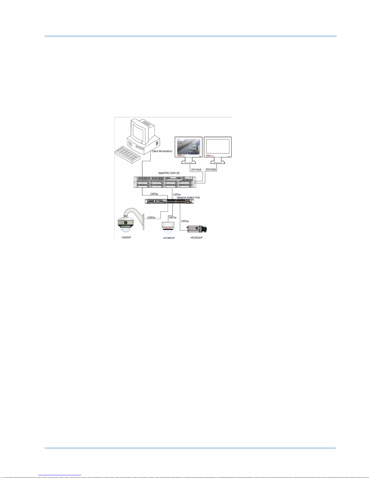
MAXPRO NVR SE SYSTEM DIAGRAM (NTSC VERSION)
The following figure illustrates the NTSC version of MAXPRO NVR SE (Standard Edition
system digram).
MAXPRO NVR Operator’s Guide 9
Page 14
ABOUT MAXPRO® NVR
MAXPRO NVR Single-box Solution System Architecture
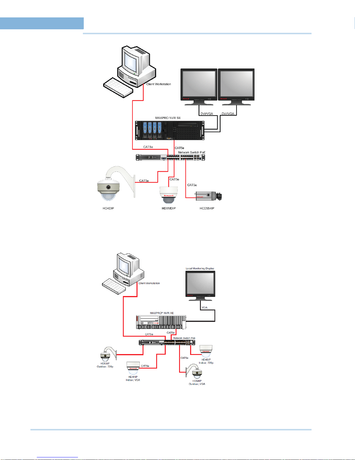
MAXPRO NVR XE SYSTEM DIAGRAM
The following figure illustrates the MAXPRO NVR XE (Xpress Edition) system diagram.
10 MAXPRO NVR Operator’s Guide
Page 15
ABOUT MAXPRO® NVR
. . . . . . . . . . . . . . . . . . . . . . . . . . . . . . . . . . . . . . . . . . . . . . . . . . . . . . . . . . .
MAXPRO NVR Software-Only Solution System Architecture
MAXPRO NVR SOFTWARE-ONLY SOLUTION SYSTEM
ARCHITECTURE
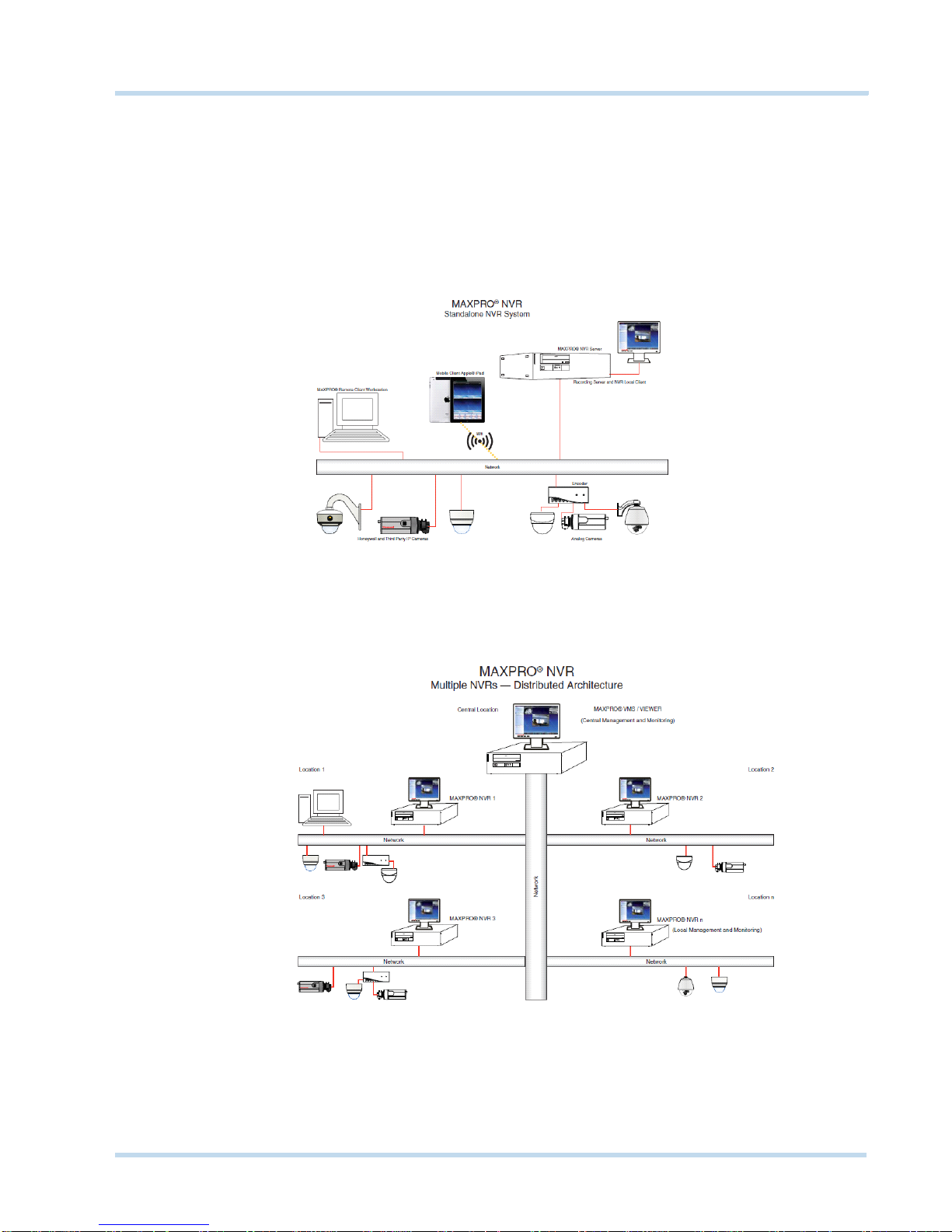
MAXPRO NVR STANDALONE SYSTEM ARCHITECTURE
The following figure illustrates the MAXPRO NVR standalone system architecture.
. . . . .
MAXPRO NVR DISTRIBUTED SYSTEM ARCHITECTURE
The following figure illustrates the MAXPRO NVR distributed system architecture.
MAXPRO NVR Operator’s Guide 11
Page 16

ABOUT MAXPRO® NVR
MAXPRO NVR Software-Only Solution System Architecture
This page is intentionally left blank
12 MAXPRO NVR Operator’s Guide
Page 17
. . . . .
. . . . . . . . . . . . . . . . . . . . . . . . . . . . . . . . . . .
MAXPRO NVR W
MAXPRO NVR Wizard is an easy three-step procedure to live video. This wizard automatically
starts each time you power-on the MAXPRO NVR system.
The MAXPRO NVR Wizard includes the following three steps.
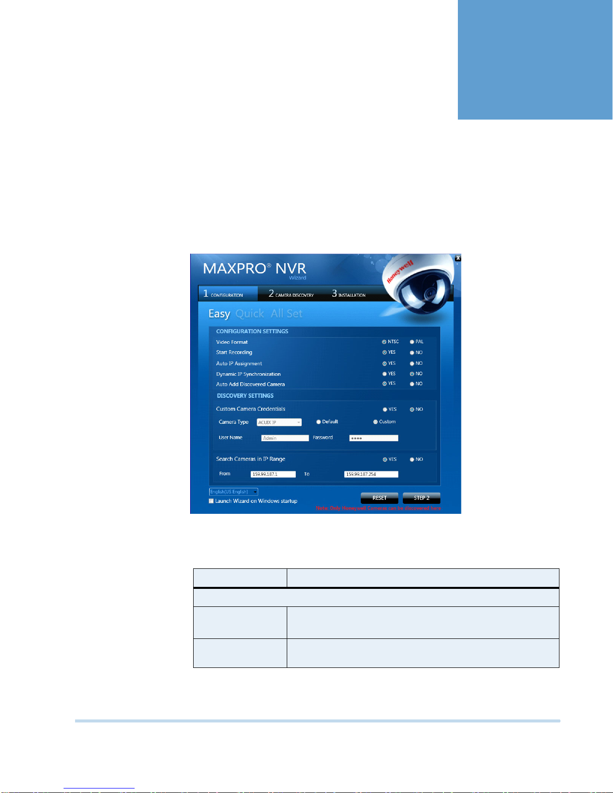
1. Step 1 - The CONFIGURATION page displays.
IZARD
• if you want to change the default settings, select “YES” or “NO”corresponding to the
fields listed in the following table or click STEP 2 to accept the default settings, and
proceed to the CAMERA DISCOVERY page in step 2.
Field Description
CONFIGURATION SETTINGS
Video Format Select “NTSC” or “PAL” based on your region.
Start Recording Start recording as soon as soon as the camera is added. 24/7
continuous recording is enabled for all the cameras.
MAXPRO NVR Operator’s Guide 13
Page 18

MAXPRO NVR WIZARD
Field Description
Auto IP
Assignment
Assigns a valid address to cameras with Automatic Private IP
Addressing (APIPA).
Note: Use this option only if you do not have a DHCP server and
want to assign an IP address in your computer network range to
the cameras.
Dynamic IP
Synchronization
MAXPRO NVR software automatically synchronizes any change
in the camera’s IP address.
For example. if a camera is restarted, and a new IP is associated
to the camera, then the MAXPRO NVR software automatically
detects the changed IP address and synchronizes it to the
camera so that live viewing and recording is not disturbed.
Auto Add
Discovered
Any newly connected camera is automatically discovered and
added to the camera’s list.
Camera
DISCOVERY SETTINGS
Custom Camera
Credentials
Camera Type This option is disabled as only Honeywell cameras are
Default Select this option to retain the default username and password
Custom Select this option to change the default username and password
Specifies the custom credentials (username and password) for
the cameras .
discovered here.
for the camera.
for the camera
Username,
Password
Search Cameras
IP Range
The username and password for the camera.
This option is enabled only if you select the Custom option.
The MAXPRO NVR system automatically detects all the cameras
in this range on the network.
From, To Type the IP range.
• Select the required language from the drop-down list. The supported languages are
French, German, Russian, Italian, Spanish, and English. The default language is English
(US English).
• Select the Launch Wizard on Windows startup check box to launch the wizard
automatically each time you start Windows.
Note: Click RESET to restore the default settings for each of fields listed in the above
table.
14 MAXPRO NVR Operator’s Guide
Page 19
MAXPRO NVR WIZARD
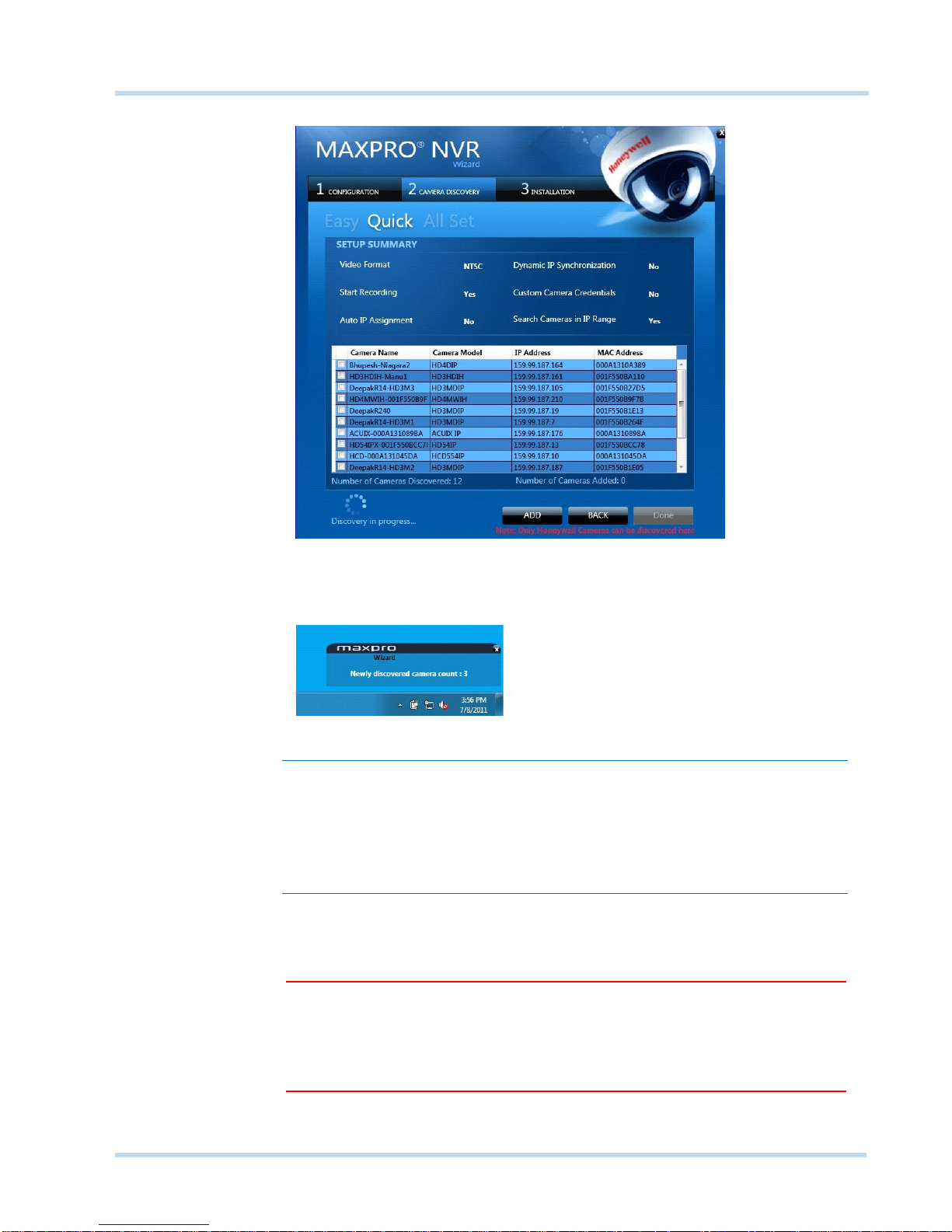
2. Step 2 - The CAMERA DISCOVERY page displays.
. . . . .
• All the settings that you have saved on the CONFIGURATION page are listed, along with
the discovered cameras. As each connected camera is discovered (notice the message
that displays on the lower right of your monitor) it is added to the list. This list disappears
as the cameras are added to the MAXPRO NVR software.
Note: The ADD button on the CAMERA DISCOVERY page displays only if you have
selected “NO” corresponding to Auto Add Discovered Camera in the
CONFIGURATION page. Use the ADD button to add discovered cameras of
your choice to the MAXPRO NVR software. Select the check boxes
corresponding to a camera from the discovered list, and click ADD to add the
cameras.
•Click BACK to return to the CONFIGURATION page or Click DONE when the number of
cameras discovered equals the number of connected cameras.
Caution: Only Honeywell cameras are discovered and added in the MAXPRO NVR
Wizard. To discover and add other Third party PSIA/ONVIF compliant
cameras, see Adding Third Party PSIA, ONVIF and AXIS Cameras on page
47. For adding and configuring Third party RTSP cameras, the RTSP
settings must be specified, see RTSP Settings on page 45.
MAXPRO NVR Operator’s Guide 15
Page 20
MAXPRO NVR WIZARD
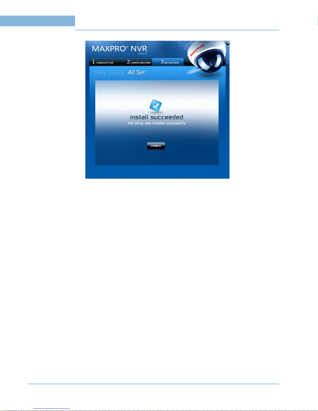
3. Step 3 - The INSTALLATION page displays.
•Click LAUNCH. The MAXPRO NVR Log On dialog displays. Please wait while the system
logs you on automatically as a Windows Logged-In User. MAXPRO NVR launches and
the Viewer tab displays. The Devices window on the left pane lists all the discovered
network cameras.
16 MAXPRO NVR Operator’s Guide
Page 21
. . . . .
. . . . . . . . . . . . . . . . . . . . . . . . . . . . . . . . . . .
L
. . . . . . . . . . . . . . . . . . . . . . . . . . . . . . . . . . . . . . . . . . . . . . . . . . . . . . . . . . .
ICENSING INFORMATION
VIEWING THE VERSION AND LICENSE INFORMATION OF
MAXPRO NVR
Caution: Honeywell’s boxed solutions, come pre-licensed or included with all
camera licenses, and this varies for MAXPRO NVR SE and MAXPRO NVR
XE.
MAXPRO NVR software comes with all the required software applications and a license for 32
channels allowing for up to 32 cameras as your system grows.
You can view the version and license information of MAXPRO NVR software from the User
menu.
1. Click the User menu (the name of the currently logged in user is displayed as the User
menu on the top right of each screen). The User menu options appear.
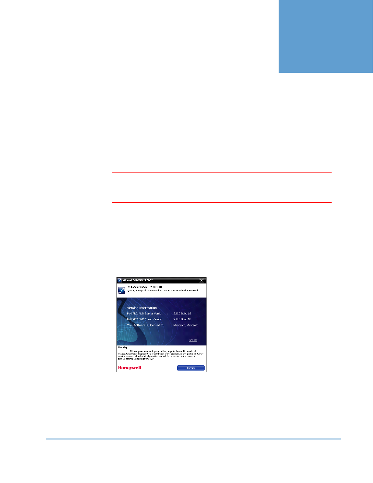
2. Click About. The version information of MAXPRO NVR displays.
1
Figure 1-1 About MAXPRO NVR
3. Click License option. The License Management Console dialog box appears.
MAXPRO NVR Operator’s Guide 17
Page 22
LICENSING INFORMATION
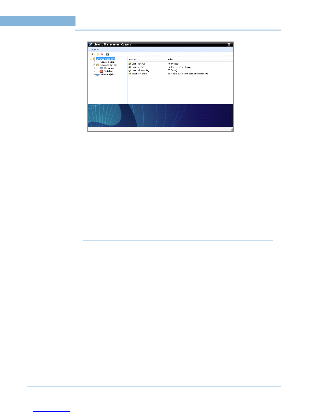
1
Viewing the Version and License Information of MAXPRO NVR
Figure 1-2 License Management Console
MAXPRO NVR setup comes with a 60 day trial period and enables you to add up to 32
cameras and 10 clients. You must purchase the license to continue using MAXPRO NVR.
REGISTRATION AND LICENSING
To register and install the license
1. Click License in the License Management Console dialog box.
2. On the License menu, click Generate Host ID File. The Browse For Folder dialog box
appears.
3. Select the path where you want to generate Host ID file, and then click OK.
Note: Host ID is a unique ID generated for the computer.
4. Refer to the MAXPRO NVR Getting Started Guide to register and get license certificate
from Honeywell.
5. Perform step 1 through 2, and then select Install License from License menu. The New
License Configuration Wizard dialog box appears.
6. Click Next. The Locate Your License File dialog box appears.
7. Click the Browse to locate your license certificate, and then click Next. The License
Comparison dialog box appears.
8. The License Comparison dialog box displays the details of the existing license and the
newly procured license . Compare the columns Existing License and Selected License
corresponding to General Features and Devices, and then click Next. The Device
Configuration Changes dialog box appears.
9. Check for the accuracy of details, and then click Next. The Confirm New License dialog
box appears.
10. Click Finish. The New License Configuration Wizard dialog box appears.
11. Click Yes.
18 MAXPRO NVR Operator’s Guide
Page 23
. . . . .
. . . . . . . . . . . . . . . . . . . . . . . . . . . . . . . . . . .
L
. . . . . . . . . . . . . . . . . . . . . . . . . . . . . . . . . . . . . . . . . . . . . . . . . . . . . . . . . . .
OGGING ON AND
LOGGING ON USING PROFILES
The MAXPRO NVR server addresses are saved in profiles. You need to select the profile
before logging on. You can set a profile as the default profile. When a profile is set as default,
you do not need to select the profile each time you log on to MAXPRO NVR. You can also
modify and delete profiles.
LOGGING ON TO MAXPRO NVR
Caution: On Honeywell provided systems a default Windows user, “Administrator”
F
AMILIARIZATION
and password, “Password1” is already configured and hence you are
automatically logged in.
2
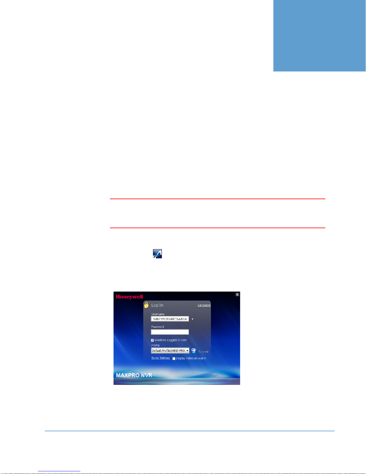
To log on to MAXPRO NVR
1. Double-click on the desktop. The Log On dialog box appears.
Or
Click Start -> Programs -> Honeywell -> MAXPRO NVR. The Log On dialog box
appears.
Figure 2-1 MAXPRO NVR Log on dialog box
2. Click the Language option, and then select the required language from the drop-down
list. The supported languages are French, German, Russian, Italian, Spanish, and English.
The default language is English (US English).
MAXPRO NVR Operator’s Guide 19
Page 24
LOGGING ON AND FAMILIARIZATION
2
Logging on using Profiles
3. Type your Username. The default user name is “Admin”.
4. Type your Password. The default password is “trinity”.
Note: Select the Windows Logged-In User check box for logging on using the
Windows user name and password. If the Windows Logged-In User check box
is cleared, the MAXPRO NVR user name and password is used for authentication.
5. If there is no profile set as default, then select the Profile corresponding to the MAXPRO
NVR server to which you want to connect.
Note: Set profiles if you have multiple MAXPRO NVRs and use the drop-down to
choose which NVR you would like to connect to.
6. Select the Display Video on Alarm check box to display the viewer as an alarm monitor.
7. Press ENTER or click . The Viewer tab displays.
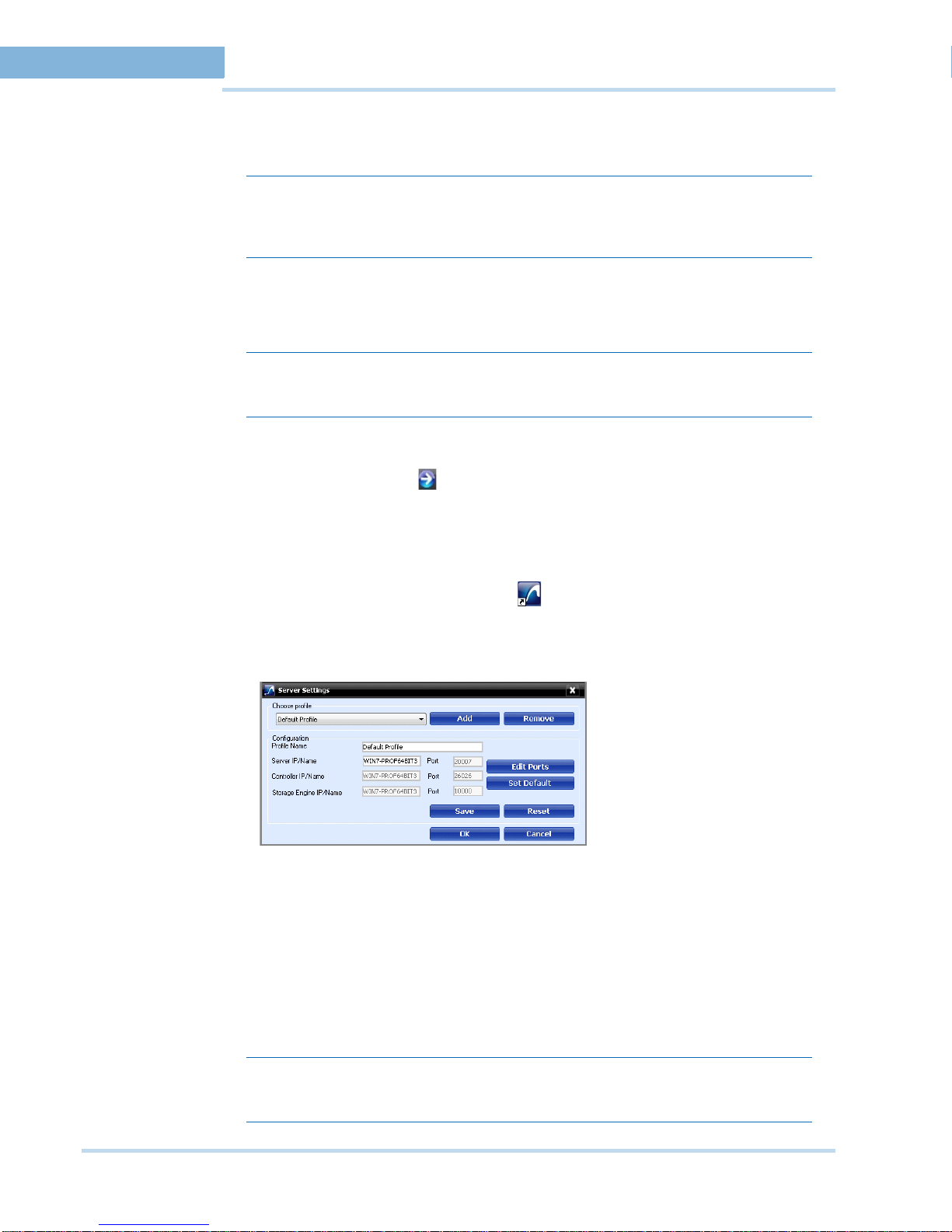
SAVING A SERVER ADDRESS IN A PROFILE
To save a server address
1. In the client workstation, double-click icon on the desktop to display the Log On
dialog box.
2. Click Server Settings. The Server Settings dialog box displays.
Figure 2-2 Server Settings dialog box
3. Click Add.
4. Type the Profile Name to identify the profile.
5. Type the Server IP/Name (numerical IP address or the network name of the MAXPRO
NVR server).
6. Click Save.
7. Click OK. The server address is saved in the profile.
Note: You can click Set Default in the server settings dialog box to set the profile as the
20 MAXPRO NVR Operator’s Guide
default profile.
Page 25
LOGGING ON AND FAMILIARIZATION
Logging on using Profiles
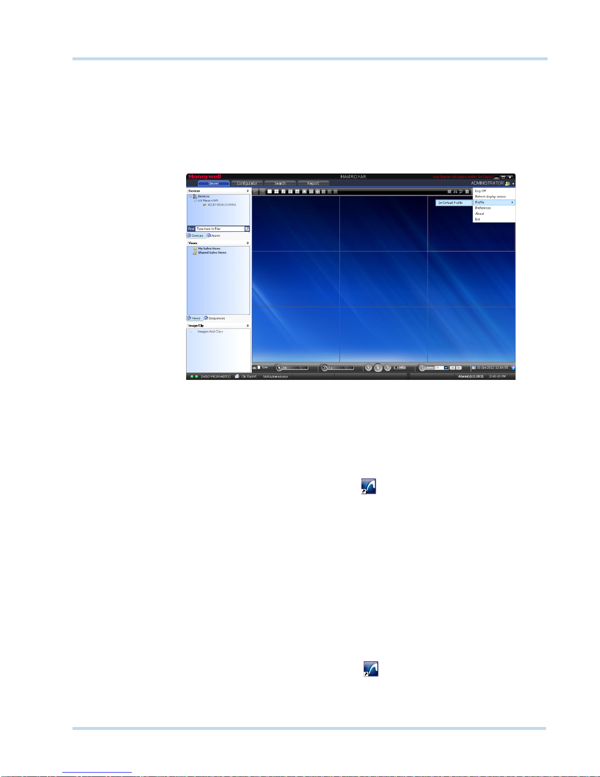
SETTING THE DEFAULT PROFILE
To set the default profile
1. Select the profile you want to set as default before logging on to MAXPRO NVR.
2. In the User menu (the name of the currently logged in user is displayed as the user menu
on the top right of each screen), click Profiles and select Set Default Profile. The profile
is set as the default profile. The default profile appears selected in the Profile box in the
Log On dialog box.
. . . . .
Figure 2-3 Setting the Default Profile
MODIFYING A PROFILE
You can modify the profile name and the server address saved in the profile.
To modify a profile
1. In the client workstation, double-click the icon on the desktop to display the Log On
dialog box.
2. Click Server Settings. The Server Settings dialog box displays.
3. In the Choose Profile box, select the profile you want to modify. The profile details
appear under Configuration in the Server Settings dialog box.
4. Change the Profile Name as applicable.
5. Change the Server IP/Name as applicable.
6. Click Save.
7. Click OK. The profile is modified.
DELETING A PROFILE
To d e let e a pr o fi le
1. In the client workstation, double-click the icon on the desktop to display the Log
On dialog box.
2. Click Server Settings. The Server Settings dialog box displays.
3. In the Choose Profile box, select the profile you want to delete.
MAXPRO NVR Operator’s Guide 21
Page 26
LOGGING ON AND FAMILIARIZATION
2
Logging on using Profiles
4. Click Remove.
5. Click OK. The profile is deleted.
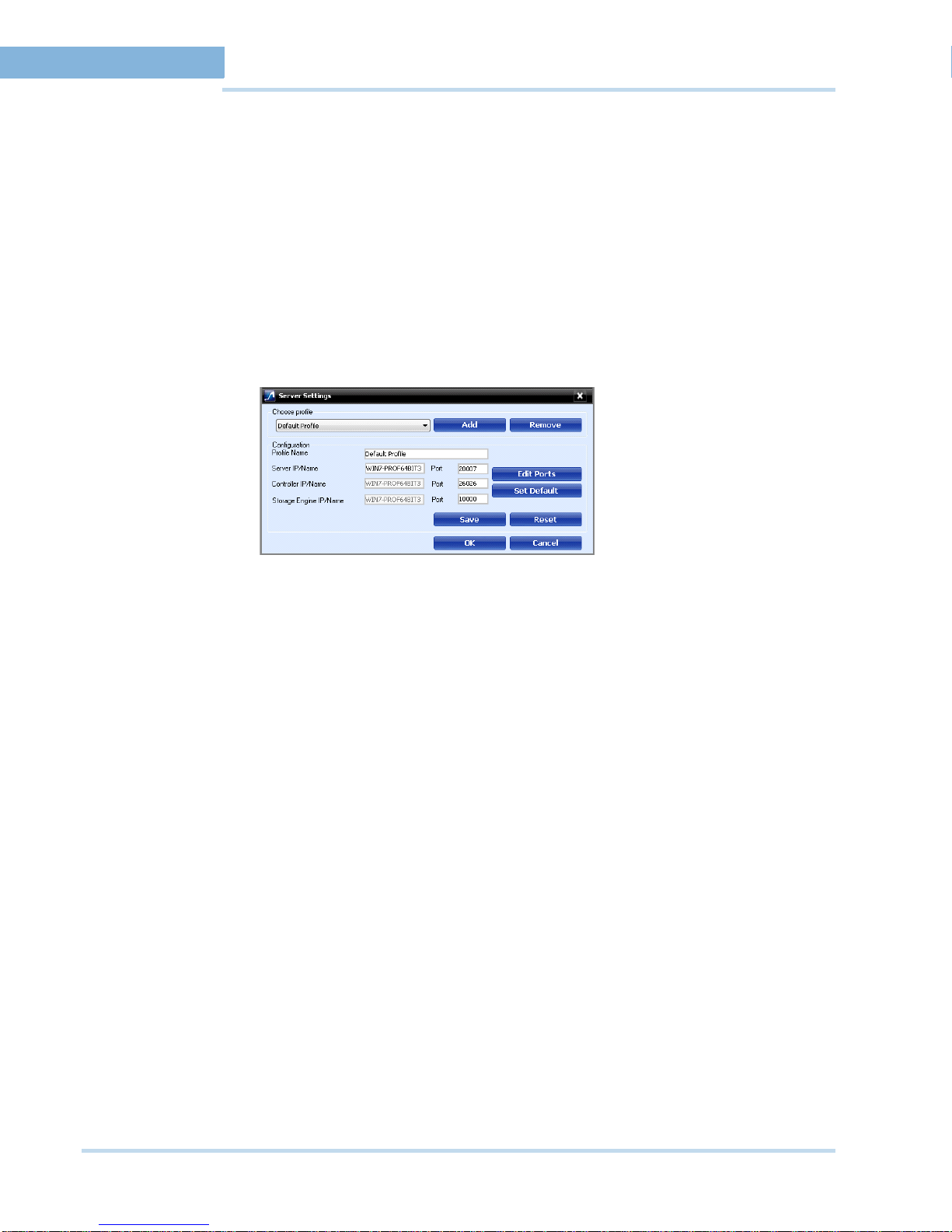
EDITING THE PORTS
The MAXPRO NVR user interface includes a provision to modify the port number associated to
the following components:
•Trinity Server
• Trinity Controller
• NeoEngine Server
To edit the ports
1. In the Server Settings dialog box, click Edit Ports. The port numbers associated to Server
IP/Name, Controller IP/Name and Storage Engine IP/Name are enabled for editing.
Figure 2-3 Editing the Ports
2. Change the port numbers as applicable.
3. Click Save.
PORT FORWARDING
The Port Forwarding feature is generally used when an Internet client wants to connect to a
particular computer in a private Local Area Network (LAN). This feature is enabled by defining
port forwarding rules in the Router. By defining these rules, you can send data using the range
of ports on the internet side to a port and IP addresses on the private LAN network.
SCENARIOS OF PORT FORWARDING
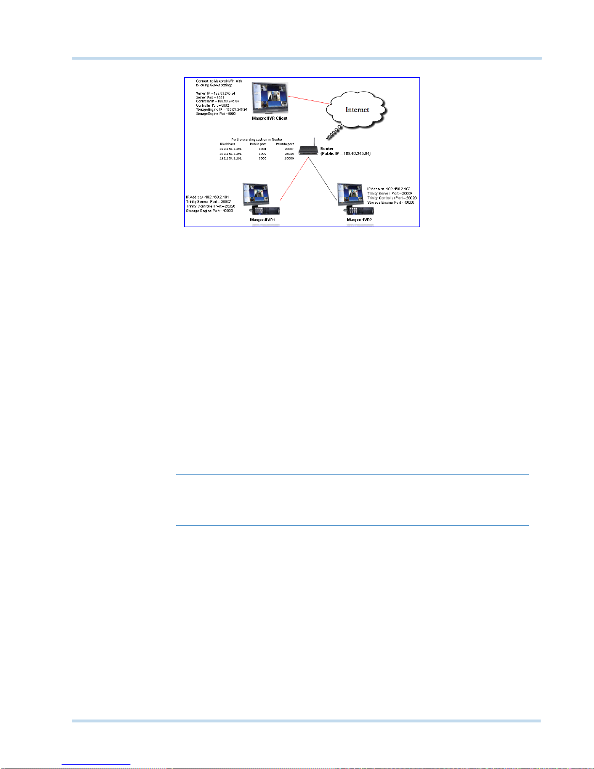
Scenario1- Services mapped to different ports
Two NVRs in a private LAN are configured behind the router, and all the services on the NVRs
are running on the default ports. In the router’s port forwarding section we need to map the
ports for each of the services running in the NVR’s. An internet MAXPRO NVR client can
connect to a NVR, by specifying the public IP address given to the router and corresponding
ports mapped in the port forwarding table in the router .
22 MAXPRO NVR Operator’s Guide
Page 27
LOGGING ON AND FAMILIARIZATION
Logging on using Profiles
Figure 2-4 Port Forwarding Scenario 1
In the above figure:
MAXPRO NVR 1 and MAXPRO NVR 2 have the default port numbers, 20007, 26026, 10000
configured for the following services respectively.
•Trinity Server
• Trinity Controller
• Storage Engine
In the Router’s Port Forwarding table, the default ports numbers for these services are
mapped to the public port numbers (8001, 8002, 8003) of the Router.
An external MAXPRO NVR client can access the MAXPRO NVRs using the following settings:
Server IP: 199.63.245.84
Server Port: 8001
Controller IP: 199.63.245.84
Controller Port: 8002
Storage Engine IP: 199.63.245.84
Storage Engine Port: 8003
. . . . .
Note: The mapping of the ports 8001, 8002, 8003 to the respective ports (20007, 26026,
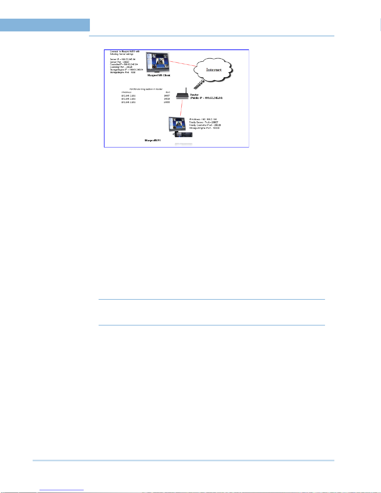
Scenario 2: Services mapped to existing ports
Single NVR is configured behind the router, and all the services on the NVR are running on the
default ports. In the router’s port forwarding section specify the default ports. The Internet
client can just specify the public IP Address and default ports to connect to the NVR. The
drawback of mapping to the same ports is that only one NVR can be behind the router.
MAXPRO NVR Operator’s Guide 23
1000) helps an external MAXPRO NVR Internet client to connect to the MAXPRO
NVR system.
Page 28
LOGGING ON AND FAMILIARIZATION
2
Logging on using Profiles
Figure 2-5 Port Forwarding scenario 2
In the above figure:
There is a single MAXPRO NVR 1 with the default port numbers, 20007, 26026, 10000
configured for the following services respectively.
•Trinity Server
• Trinity Controller
• Storage Engine
In the router’s port forwarding table, the default ports numbers for these services are specified.
An external MAXPRO NVR client can access the MAXPRO NVRs using the following settings:
Server IP: 199.63.245.84
Server Port: 20007
Controller IP: 199.63.245.84
Controller Port: 26026
Storage Engine IP: 199.63.245.84
Storage Engine Port: 10000
Note: In this scenarios, as ports are not mapped in the router, you can connect to only
LOGGING OFF
You can log off from MAXPRO NVR from the User menu. The name of the currently logged in
user is displayed as the User menu on the top right of each screen.
To log off from MAXPRO NVR
1. Click the User menu. The user menu options appear.
2. Click Log Off. The Logon dialog box displays after logging off from MAXPRO NVR.
CLOSING THE MAXPRO NVR USER INTERFACE
You can close the MAXPRO NVR user interface from the User menu. The name of the currently
logged in user is displayed as the User menu on the top right of each screen.
To close the MAXPRO NVR
1. Click the User menu. The user menu options appear.
24 MAXPRO NVR Operator’s Guide
one MAXPRO NVR from an external MAXPRO NVR Client.
Page 29
LOGGING ON AND FAMILIARIZATION
. . . . . . . . . . . . . . . . . . . . . . . . . . . . . . . . . . . . . . . . . . . . . . . . . . . . . . . . . . .
Familiarizing with the MAXPRO NVR User Interface
2. Click Exit. A dialog box appears prompting you to confirm the action.
3. Click Ye s.
FAMILIARIZING WITH THE MAXPRO NVR USER
INTERFACE
The user interface of MAXPRO NVR is easy-to-use because of its intuitive icons and userfriendly features. You can configure the devices in the video surveillance network through the
MAXPRO NVR user interface. The user interface consists of tabs, tree-structures, status bar,
floating windows, and icons. On opening the user interface, you see the following four tabs:
Viewer, Configurator, Search and Report. Based on the tab you select, windows, tree
structures, and other settings relevant to the tab appear on the screen.
A status bar is displayed at the bottom of the user interface. The status bar displays the
following: the connection status with the MAXPRO NVR server and controller, the status of clip
creation, the role of the user, the number of unacknowledged alarms, and the time.
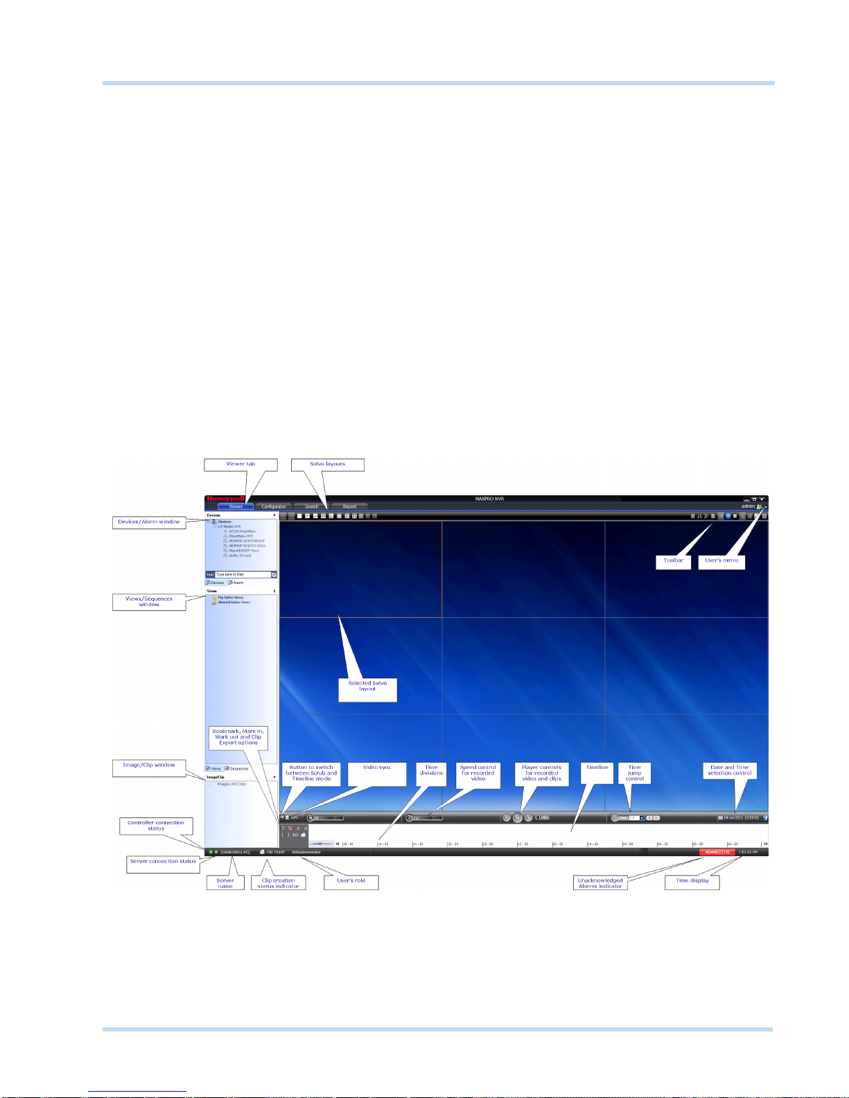
VIEWER TAB
The following figure illustrates the Viewer tab.
. . . . .
Figure 2-1 Viewer tab
MAXPRO NVR Operator’s Guide 25
Page 30

LOGGING ON AND FAMILIARIZATION
2
Familiarizing with the MAXPRO NVR User Interface
The following components are displayed on the screen.
Component Description
Devices/Site window A floating window that displays recorder and cameras in a
tree structure. You can select one or more devices from
the Devices window to view video in the Salvo Layout.
Intellisense search
The Intellisense search option simplifies the search for
cameras. When a part of the camera name is typed in the
text box, the Intellisense search displays the list of
cameras that are connected to the MAXPRO NVR in the
Devices window. For example, if you are searching for
Camera 2 connected to MAXPRO NVR, then type Ca in
the text box. The list of camera names which contain 'ca'
are displayed.
Intellisense search also supports wild characters while
searching. For example:
• ca* — camera names that begin with the 'ca' are
displayed.
• *ca — camera names that end with the 'ca' are
displayed.
• *ca* — camera names that contain 'ca' are displayed.
• ! ca — cameras that do not have 'ca' in their name are
displayed.
Select the required filter string and click on the filter
button.You can toggle between the Filter On and Off
mode using the option or right-click , and select
between Filter ON and Filter OFF. The hot key to activate
intellisense search is F4.
Devices /Site window
continued...
The context menu options in the Devices window include:
• Show Live - to view live video.
• Preview - to preview the live video.
• Refresh - to refresh the camera status.
• Refresh from Device - to refresh the camera status
from the device.
• Show Device ID - to display the device ID.
• Hide Device ID - to hide the display of device ID.
• Sort By Name - to sort the list of devices by name. By
default, names are sorted in ascending order.
Alarm window Click to display a floating window that lists the alarms. You
can acknowledge and clear the alarms from this window.
See Alarms on page 77.
26 MAXPRO NVR Operator’s Guide
Page 31

LOGGING ON AND FAMILIARIZATION
Familiarizing with the MAXPRO NVR User Interface
Component Description
Image/Clip window Click to display a floating window that lists the images and
clips in a tree structure. You can select the images and
clips to view.
You can right-click on the images folder or the images to
display context menu. The context menu options include,
• Refresh - to refresh the images/clips in the respective
folder.
• Show Video - to show the video.
• Delete - to delete an image.
• Show In Folder - to view the folder in which the
images are stored.
See Images and Clips on page 73.
Sequences window Click to display a floating window that lists the sequences.
You can play the sequence using the play sequence
action.
You can right-click on the devices to display a context
menu. The context menu options include:
• Play Sequence - to play any sequence.
• Show Device ID - to display the device ID.
• Sort By Name - to sort the list of sequences by name.
By default, names are sorted in ascending order.
See Configuring the Sequences on page 51.
. . . . .
MAXPRO NVR Operator’s Guide 27
Page 32

LOGGING ON AND FAMILIARIZATION
2
Familiarizing with the MAXPRO NVR User Interface
Component Description
Views window A floating window that lists the salvo views. The View
window consists of My Salvo views and Shared Salvo
views. Salvo views corresponding to the logged on user
are listed under My Salvo Views in the Views window.
You can copy a salvo view from My Salvo Views to
Shared Salvo Views using the drag and drop option or
right-click and select Add to Shared Salvo Views.
Similarly, you can copy a salvo view from Shared Salvo
Views to My Salvo Views using the drag and drop option.
Devices grouped under Shared Salvo Views are
displayed on all client workstations irrespective of the
logged in user.
To add a salvo view to Shared Salvo Views, right-click on
a salvo view, and then click Add to Shared Salvo Views.
You can copy a salvo view from Shared Salvo Views to
My Salvo Views by dragging and dropping a salvo view.
You can right-click on the salvo view to display a context
menu. The context menu options include:
• Show - to view the salvo view.
• Rename - to rename a salvo view.
• Remove - to remove a salvo view.
• Save - to save a salvo view.
• Add to Shared Salvo Views - to add a salvo view to
the Shared Salvo views.
• Show Device ID - to display the device ID.
• Hide Device ID - to hide the display of device ID.
• Refresh - to refresh the salvo views in the list.
• Sort By Name - to sort the list of salvo views by
name. By default, names are sorted in ascending
order.
See Salvo View on page 59.
Salvo Layout An arrangement of panels in which video is displayed.
See Salvo Layouts and Panels on page 57.
Timeline window A window that enables you to view video from a specified
date and time. It also consists of other features such as
mark in and mark out and selective viewing using
bookmarks. You can also create clips from video
recordings. You can select between the scrub mode or full
timeline mode using the icon. See Video Recording
and Viewing on page 63.
28 MAXPRO NVR Operator’s Guide
Page 33

Familiarizing with the MAXPRO NVR User Interface
CONFIGURATOR TAB
The following figure illustrates the Configurator tab.
LOGGING ON AND FAMILIARIZATION
. . . . .
Figure 2-2 Configurator tab
The settings in the Configurator tab enable you to add and configure the video devices and
set up the MAXPRO NVR system.
Components Description
System tab Helps you to configure the system level
information for MAXPRO NVR.
Disk tab Helps you to configure the disk settings for
video storage.
Camera tab Helps you to configure the camera settings.
Schedules tab Helps you to configure the schedules for live
video.
IO tab Helps you to configure the input and output
for a camera.
Sequence tab Helps you to select a sequence of cameras
for live video.
User tab Helps in user administration.
MAXPRO NVR Operator’s Guide 29
Page 34

LOGGING ON AND FAMILIARIZATION
Sear ch
filter
Selecti ng
Recorder
Selecting
Cameras
associated to the
Record er
Sele c tin g th e
Events
Selecting the
Date and Time
Searc h result s
wind ow
Sear c h ta b Salvo
layo uts
Toolbar
2
Familiarizing with the MAXPRO NVR User Interface
SEARCH TAB
The following figure illustrates the Search tab.
Figure 2-3 Search tab
You can search for recorded video and events in MAXPRO NVR from the Search tab.
30 MAXPRO NVR Operator’s Guide
Page 35

REPORT TAB
. . . . . . . . . . . . . . . . . . . . . . . . . . . . . . . . . . . . . . . . . . . . . . . . . . . . . . . . . . .
Repo r t tab
Ev e n t H isto ry
Repor t
Displays the
content for the
selected report
Operator Log Report
Repor t conte nt
area
The following figure illustrates the Report tab.
LOGGING ON AND FAMILIARIZATION
Setting Preferences
. . . . .
Figure 2-4 Report tab
SETTING PREFERENCES
The Preferences option in the User menu enables you to configure the general settings and
the On Screen Display (OSD) settings. In general settings, you can configure the frame rate
for panels that are not selected in the salvo layout, the video rendering settings, the video to
be displayed for alarms, and the alarm threshold settings. The OSD settings can be
configured to change the font properties like type, color, and size for the text that appears over
the video displayed in a panel.
You can also select the default values for the general and OSD settings using the Preferences
option.
SETTINGS FOR VIDEO RENDERING
There are two types of rendering modes, Default and No Video Display. The Default
rendering is the recommended mode which enables the user to view live video from multiple
cameras at optimum quality. Selecting No Video Display does not display any video. You can
also set the frame rate for panels that are not selected in the salvo layout. The frame rate for
the panels that are not selected can be set to improve the video signal transmission over
lower bandwidth networks.
To select the video rendering option
1. Click the Preferences option in the user menu. The Preferences dialog box displays. By
default, the General Settings tab is selected.
MAXPRO NVR Operator’s Guide 31
Page 36

LOGGING ON AND FAMILIARIZATION
2
Setting Preferences
Figure 2-5 General Settings tab
2. Click the Rendering Settings tab.
Figure 2-6 Rendering Settings tab
3. Select the Renderer Option (Default/No Video Display) for video rendering.
4. Select the Mange CPU Load (Throttle Frame Rate) check box if you want to throttle the
frame rate if the CPU usage reaches 90 per cent.
5. Select the Show Time Stamp For Live check box if you want the camera name and time
to be displayed on the live video.
6. Select the Deinterlace Selected Panel check box if you want to deinterlace the selected
panel.
7. Select the check box beside Set FPS Limit For Unselected Panel.
8. Select the FPS Limit. The default frame rate is 5 fps and is the recommended setting for
unselected panels.
9. Click Apply.
10. Click OK to close the dialog box.
PAUSING THE VIDEO RENDERING
You can pause the video rendering to momentarily stop the rendering of video when a tab that
does not display video is selected (for example, when the Report tab is selected, the video
rendering can be paused to improve the application performance). The rendering of video
starts again when you select a different tab in the user interface.
To select the tab which pauses video rendering
1. Click the Preferences option in the User menu. The Preferences dialog box displays. By
default, the General Settings tab is selected.
32 MAXPRO NVR Operator’s Guide
Page 37

LOGGING ON AND FAMILIARIZATION
Setting Preferences
2. For Pause Video Rendering, select the check box next to the tab names that you want to
select.
Figure 2-7 Settings for pausing the Video Rendering
3. Click Apply.
4. Click OK to close the dialog box.
SETTINGS FOR ALARM PREVIEW PANE
When the video related to an alarm is played from the Alarm window, the salvo layout
changes to a four panel layout. You can define the video display for each panel namely, Pre
Alarm, Post Alarm, Live, and On Alarm. The following table defines these options.
. . . . .
Option Description
Pre Alarm The video before the occurrence of the event that triggered the
alarm is played.
Post Alarm The video after the occurrence of the event that triggered the alarm
is played.
Live Live video is played.
On Alarm The video is played from the occurrence of the event that triggered
the alarm.
Note: You can view video related to alarms for the cameras connected to MAXPRO
NVR. For Pre Alarm, Post Alarm, and On Alarm, the video is played only when the
video recording pertaining to the date and time of alarm is available.
To define the video display for each preview panel
1. Click the Preferences option in the User menu. The Preferences dialog box displays. By
default, the General Settings tab is selected.
2. Select the video option for each panel corresponding to Preview Pane. When you select
Pre Alarm and Post Alarm, a dialog box appears. Select the time in seconds for which
you want to view video related to pre alarm and post alarm in the dialog box and click
OK.
MAXPRO NVR Operator’s Guide 33
Page 38

LOGGING ON AND FAMILIARIZATION
2
Setting Preferences
Figure 2-8 Settings for the Alarm Preview Pane
3. Click Apply.
4. Click OK to close the dialog box.
SETTING THE ALARM THRESHOLD VALUE
When configuring the event settings for a recorder and camera, you can specify a value
known as the Severity Level for each event. When the event occurs, the Severity Level value
is compared with the value in the Alarm Severity Threshold box in the Preferences dialog
box. The alarm is triggered only when the Severity Level value is greater than the Alarm
Severity Threshold value.
For example, the alarm is triggered if the Severity Level for an event is 50 and the Alarm
Severity Threshold value is 40.
To set the Alarm Severity Threshold value
1. Click the Preferences option in the User menu. The Preferences dialog box displays. By
default, the General Settings tab is selected.
2. Under Server Level Settings, type the Alarm Severity Threshold.
Figure 2-9 Setting the Alarm Threshold
3. Click Apply.
4. Click OK to close the dialog box.
CONFIGURING THE SNAPSHOT CLIP EXPORT SETTINGS
You can configure the time interval for the exported snapshot.
To configure the time interval for the exported snapshot
1. Click the Preferences option in the User menu. The Preferences dialog box displays. By
default, the General Settings tab is selected.
34 MAXPRO NVR Operator’s Guide
Page 39

LOGGING ON AND FAMILIARIZATION
Setting Preferences
2. Under SnapShot Clip Export Settings, select the Clip Export time in seconds.
Figure 2-10 Settings for SnapShot Clip Export
3. Click Apply.
4. Click OK to close the dialog box.
CONFIGURING THE OSD SETTINGS
You can configure the OSD settings to change the properties such as type, color, and size of
the text that appears over the video displayed in a panel.
To set the font properties
1. Click the Preferences option in the User menu. The Preferences dialog box displays.
2. Click the OSD Settings tab.
. . . . .
Figure 2-11 OSD Settings tab
3. Click Edit and select the font and color properties in the dialog box.
4. Click OK to close the font properties dialog box.
5. Click Apply in the Preferences dialog box.
6. Click OK to close the Preferences dialog box.
CONFIGURING THE TIMELINE SETTINGS
To configure the timeline settings
1. Click the Preferences option in the User menu. The Preferences dialog box displays.
2. Click the Timeline Settings tab.
MAXPRO NVR Operator’s Guide 35
Page 40

LOGGING ON AND FAMILIARIZATION
2
Setting Preferences
Figure 2-12 Timeline Settings tab
3. Under Timeline Jump Control Configuration, set the time for the intervals (Interval 1 to
Interval 6) as applicable.
4. Under Snapshot Duration Settings, select the Daywise or Hourwise option button as
applicable.
5. Click Apply.
6. Click OK to close the Preferences dialog box.
CONFIGURING THE DIAGNOSTIC SETTINGS
To configure the diagnostic settings
1. Click the Preferences option in the User menu. The Preferences dialog box displays.
2. Click the Diagnostic Settings tab.
Figure 2-13 Diagnostic Settings tab
3. Under Change log level settings, select the check boxes corresponding to logs as
applicable.
4. Click Apply.
5. Click OK to close the Preferences dialog box.
CONFIGURING THE DEFAULT SETTINGS
To apply the default settings
1. Click Reset to apply default settings while setting preferences.
2. Click System Defaults to apply the system default settings while setting preferences.
36 MAXPRO NVR Operator’s Guide
Page 41

. . . . .
. . . . . . . . . . . . . . . . . . . . . . . . . . . . . . . . . . .
C
ONFIGURING
3
MAXPRO NVR
Configuring MAXPRO NVR involves the following tasks.
• Configuring the System settings
• Configuring the Disk settings
• Configuring the Cameras
• Configuring the Schedules
• Configuring the Input and Output for a camera
• Configuring the Sequences
• Performing User administration
CONFIGURING THE SYSTEM SETTINGS
The System settings enable in configuring the following:
• General System Settings
• Event Recording Settings
• Email Settings
• Holiday/Exception Settings for Schedules
To configure the system settings
•Click the Configurator tab. The System page appears by default.
Figure 3-1 System page
GENERAL SYSTEM SETTINGS
The general settings enable configuring of the device address, device name, and device
description for MAXPRO NVR.
MAXPRO NVR Operator’s Guide 37
Page 42

CONFIGURING MAXPRO NVR
3
To configure the general system settings
1. Under General Settings
•The Device Address displays by default. You can type a new device address as
applicable.
•The Device Name displays by default. You can type a new device name as
applicable
•The Description of the device displays by default. You can type a new description as
applicable.
Note: The information in the Device Address and the Device Name fields is
mandatory.
EVENT RECORDING SETTINGS
The event recording settings enable configuring of the times associated to video motion
detection and user based recording.
2. Under Event Recording Settings
•The Pre-event Time (the length of time (in seconds) recording takes place before
motion is detected) and displays by default. Select a new Pre-event Time as
applicable.
•The Record for (the length of time (in seconds) recording takes place after motion is
detected) displays by default. Select a new Record for Time as applicable.
•The User based Recording Time (duration for which the recording is done after the
user action) displays by default. Select a new User based Recording Time as
applicable. The user based recording is the recording initiated by the user manually
and is applicable for all the cameras connected to MAXPRO NVR.
Note: To start user based recording, right-click the panel displaying live video and click
Start Recording. To stop the recording, right-click the panel displaying live video
and click Stop Recording.
EMAIL SETTINGS
The email settings enable configuring of the SMTP server settings for email communication of
events.
3. Under Email Settings
• Type the SMTP Server Name.
•The Port displays by default. Type a new Port number as applicable.
• Type the User Name of the user.
• Type the Password of the user.
Note: Select the Use Default Credentials check box if you want to use the credentials
that are used while logging on.
38 MAXPRO NVR Operator’s Guide
Page 43

CONFIGURING MAXPRO NVR
Note: Select the Stop Email Service check box, if you do not want to send an e-mail
from the configured settings.
HOLIDAYS/EXCEPTIONS SETTINGS
The holidays/exceptions settings enable setting of the holiday and exceptions for schedule
based video recording.
4. Under Holidays/Exceptions
To set holidays and exceptions
• Select a day from the calendar, and click Set as Holiday to set the selected day
as holiday. The selected holiday displays under List of Holidays.
• Select a day from the calendar, and click Set as Exception to set the selected
day as exception. The selected exception displays under List of Exceptions.
To remove holidays and exceptions
• Under List of Holidays, select the check box for the holiday you want to
remove, and then click Remove Holiday.
• Select the check box for the exception you want to remove, and click Remove
Exception.
5. Click Save to save the information or click Reset to clear the information entered.
. . . . .
CONFIGURING THE DISK MANAGEMENT SETTINGS
Disk Management helps you to configure the disk settings for saving the recorded video. All
the drives available on the MAXPRO NVR system are automatically added in the Disk
Management page.
To configure the Disk Management settings
1. Click the Configurator tab. The System page displays by default.
2. Click the Disk tab to open the Disk Management page.
Figure 3-2 Disk Management page
MAXPRO NVR Operator’s Guide 39
Page 44

CONFIGURING MAXPRO NVR
3
All the drives available on the MAXPRO NVR system are listed.
Note: By default, the check boxes corresponding to all the drives except C:\ are selected.
C:\ is reserved for the Operating System data.
3. The following information displays under Disk Management.
• Drive Name - displays the drive name such as C:\, D:\ and so on.
• Drive Type - displays the drive type (Fixed or Network).
Note: By default, only the fixed drives are listed. See step 5 to explicitly add a network
drive or fixed drive.
• Storage Path - displays the default storage path for saving the recorded video. You
can type a new path for saving the recorded video
• Selected for Storage - By default, this check box is selected for all the fixed drives
that are listed except C: To disable video recording on a particular drive, clear the
Select for Storage check box corresponding to the drive.
• Total Space (GB) - displays the total space available on the drive.
• Free Space (GB) - displays the free space available on the drive.
• Current Recording Drive - displays a status indicator indicating that recording is
taking place on the drive. “Green” indicates that current recorded video is saved on
the drive.
4. Under Disk Space
The overall drive statistics specified for the recorded video at any point of time is indicated
by the following fields:
• Total available disk space - displays the total storage space available on the
drives used for saving the recorded video.
• Used non video disk space - displays the disk space used by non video data
on the drives.
• Used video disk space - displays the disk space on the drives used for saving
the recorded video.
• Free disk space - displays the free disk space available on the drives.
40 MAXPRO NVR Operator’s Guide
Page 45

CONFIGURING MAXPRO NVR
You can also view a graphical illustration of the drive statistics with legends for each of the
above fields.
Figure 3-3 Graphical Illustration
•In the Recording recycle at box, type a value. The Recording recycle refers to a
state when the oldest video recordings are automatically deleted, if there is no
disk space on the drives for new video recordings.
•In the Low disk alarm at box, type a value. The Low disk alarm refers to a state
when the space on the drives for video storage is nearing the maximum size of
the drives.
. . . . .
Caution: The Low disk alarm at value must be always greater than the Recording
recycle at value.
Note: Click Refresh to refresh the information under Disk Space at any point of time.
5. Click Add Drive to add a fixed drive or a network drive.
• The fixed drive that you are adding must be available on the MAXPRO NVR system,
else an “Invalid Drive” text displays in the Total Space (GB) column.
• Add a network drive in the following format: \\<IP address >\<folder name> for
example, \\192.168.1.12\Recorded Clips.
Note: The Network drive added must be valid with proper folder permissions set for the
installed default user, else an “Invalid Drive” text displays in the Total Space
(GB) column.
6. Click Save to save the information or click Reset to clear the information entered.
MAXPRO NVR Operator’s Guide 41
Page 46

CONFIGURING MAXPRO NVR
3
Note: To remove a drive, select the check box corresponding to the drive, and then
click Delete.
CONFIGURING THE CAMERAS
Cameras are sources for a video input in MAXPRO NVR. The maximum number of cameras
that can configured in MAXPRO NVR is 32.
ADDING THE CAMERAS
To add cameras
1. Click the Configurator tab. The System page displays by default.
2. Click the Camera tab to open the Camera page.
Figure 3-4 Camera page
3. Under Discover cameras here
• Click to discover the cameras in the network. By default, the check boxes
corresponding to all the discovered cameras are selected.
Note: The cameras are added based on the Advanced Discovery Settings. See
•Click Add to add all the discovered cameras. To add only specific cameras, first clear
the check boxes of the cameras you do not want to add, and then click Add. The
selected cameras appear under the Camera pane.
42 MAXPRO NVR Operator’s Guide
Configuring the Advanced Discovery Settings for more information.
Page 47

CONFIGURING MAXPRO NVR
Note: The cameras added have the default parameters for all their settings.
4. Under the Camera pane, select a camera to change the default parameters for the
following settings.
• Enable/Disable - Enables or disables a camera for recording and live video. By
default the check box corresponding to a camera to enable live video preview is
selected. To disable live video preview, clear the check box corresponding to a
camera. The live video appears under Video Preview at the bottom right corner of
the Camera page.
• Number - Displays the camera number. You cannot modify the camera number.
• Camera Name - Displays the camera name. You can type a new camera name
limited to a maximum of 50 alphanumeric characters.
• IP Address - Displays the IP address of the camera. You can type the new IP
address for the camera as applicable.
• Camera Type - Displays the type of camera.
Note: For the camera type, “Generic - RTSP, you must specify the RTSP settings for the
camera in the Camera Advanced Settings pane. See RTSP Settings for more
information.
. . . . .
• Fixed/PTZ - Indicates whether the camera is a PTZ or fixed.
Note: By default, ACUIX cameras are PTZ enabled.
• Continuous Recording - All cameras added are defaulted to “24/7” recording. You
can choose a different option from the drop-down list.
• Event Based Recording - This is “None” by default. Select an option from the dropdown if you want to do motion based recording.
• User Name- Displays the default user name, “Admin” for the camera. You can type a
new user name for the camera as applicable.
Note: Change this only if the user has been changed on the camera.
• Password - Displays the password, if any, for the camera. You can type a new
password for the camera as applicable.
Note: Change this only if the password has been changed on the camera.
• Video Channel Number - Displays the video channel number for the camera.
5. Click to open the Camera Advanced Settings pane.
MAXPRO NVR Operator’s Guide 43
Page 48

CONFIGURING MAXPRO NVR
3
Figure 3-5 Camera Advanced Settings pane
Note: The Camera Advanced Settings pane is disabled when there are no cameras
available in the system.
6. Click Launch Web View for Advanced Set Up to launch the web page for the camera.
Use the camera's web page to view IP and firmware settings, bit rate statistics, camera
exposure, day night and white balance settings, and set up video motion detection and
other analytic events.
7. Under Live Quality Settings
• Select the Video Format (NTSC or PAL). The NTSC and PAL are the widely used
video formats.
•The Compression Format is defaulted to “MPEG4”.
•The Resolution is defaulted to a fixed value based on the camera model (for
example, HD3MDIP model defaults to 1280 x 720 resolution).
• Select the PTZ Sensitivity for PTZ camera. Available PTZ options are: Low, Normal,
High and Maximum.The higher the compression, the lower the bit rate, the lower the
image quality and the more processor power is consumed.
Note: The PTZ Sensitivity field is not available for fixed cameras.
•The Compression is defaulted to “Medium”. You can select a new Compression
ratio as applicable.
• Select the FPS for a camera. FPS refers to the number of pictures displayed in
exactly one second. FPS is a measure of how much information is used to store and
display motion video. The term applies to digital video. Each frame is a still image;
displaying frames in quick succession creates the illusion of motion.
44 MAXPRO NVR Operator’s Guide
Page 49

CONFIGURING MAXPRO NVR
Note: For live streaming, 30 FPS is the default frame rate in NTSC format and 25 FPS is
the default frame rate in PAL format.
•The GOP is defaulted to “5”. Type a new GOP as applicable. Group of Pictures
(GOP) are individual frames (number of pictures) that are grouped together and
played back for viewing. A GOP consists of “IFrame” picture type that represents a
fixed image independent of other picture types. Each GOP begins with this type of
picture.
8. Under Record Quality Settings
• Select the FPS for Background recording.
• Select the FPS for Event based recording.
Live/Recording Quality can be varied by controlling GOP. The formula for this is calculated
as follows: Recording Quality resulting FPS = Live FPS/(GOP*I Frame Number for
recording).
For example, in the following table if Live FPS is configured as “30” and Continuous
recording is set to record “Every I frame” and Event recording is set to “Same as Live” with
GOP value set to “5” , the result is 6 FPS continuous recording quality and 30 FPS event
recording quality.
. . . . .
Note: GOP value below 5 may not be achieved from all the cameras.
9. Under Recording Deletion Settings
• Select the Event Recording clip deletion duration.
• Select the Continuous Recording clip deletion duration.
RTSP SETTINGS
Real Time Streaming Protocol (RTSP) is a control protocol for streaming video over the
Internet. For the camera type “Generic RTSP”, you must specify the following RTSP settings.
MAXPRO NVR Operator’s Guide 45
Page 50

CONFIGURING MAXPRO NVR
3
Figure 3-6 RTSP Settings
• Type the RTSP URL. Click for help on RTSP URLs format that can be assigned
to different camera types.
Note: The Help that opens lists only a few manufacturers. Most cameras are RTSP, and
all RTSP 3rd party cameras can be configured. If the RTSP URL format for a
particular camera type is not listed in the Help, then the URL format can be
obtained from the camera manufacturer.
•Click Get Configuration to get the resolution and compression format for the
camera.
Note: For RTSP, all settings like FPS must be configured on the camera web page.
10. Click Save.
Note: If a particular camera is not discovered by the system, you can add it manually by
clicking New.
UPDATING THE CAMERAS
You can modify the settings of a camera to change the camera name, IP address, camera
type, fixed/PTZ, advanced camera settings, and so on. You can update the camera settings
only if you have admin rights.
To update a camera
1. Click the Configurator tab. The System page displays by default.
2. Click the Camera tab to navigate to the Camera page. The list of cameras configured are
displayed.
3. Select the row corresponding to the camera you want to modify.
4. Change the settings such as camera name, IP address, and so on.
46 MAXPRO NVR Operator’s Guide
Page 51

CONFIGURING MAXPRO NVR
5. Click Save.
DELETING THE CAMERAS
To delete a camera
1. Click the Configurator tab. The System page displays by default.
2. Click the Camera tab to navigate to the Camera page.
3. Select the check box corresponding to the camera you want to delete.
4. Click Delete. A confirmation message appears at the bottom of the display area.
5. Click Ye s. The selected camera is deleted.
CONFIGURING THE ADVANCED DISCOVERY SETTINGS
The advanced discovery settings enable you to choose between NTSC and PAL format for a
camera. Advanced discovery settings can be configured for cameras connected to MAXPRO
NVR.
Note: Advanced Discovery Settings are only applicable for PSIA, ONVIF compliant and
AXIS cameras.
. . . . .
To configure the Advanced Discovery Settings
1. On the Camera page>Advanced Discovery Settings pane, perform the following:
• Select “NTSC” or “PAL” from Set Video Format list.
•Type a Username for the camera.
•Type a Password for the camera.
Note: You are prompted to type the username and password for a PSIA, ONVIF and
AXIS cameras.
•Click Apply to save the changes or click Reset to clear the information entered.
Note: The username and password entered is applicable for all NTSC or PAL cameras.
However, the username and password can be changed while configuring a
particular camera.
ADDING THIRD PARTY PSIA, ONVIF AND AXIS CAMERAS
The Third party PSIA, ONVIF and AXIS cameras that are discovered in the MAXPRO NVR user
interface do not display the model name. However, the Camera Type field associated to the
ONVIF, PSIA, and AXIS cameras displays “ONVIF DEVICE”, “PSIA DEVICE” and “No Streamer
Type” in the Discovery window on the Camera page.
MAXPRO NVR Operator’s Guide 47
Page 52

CONFIGURING MAXPRO NVR
3
Figure 3-7 Camera Type field displaying “ONVIF DEVICE” for a ONVIF camera
You must add the discovered camera(s) using the Add button to view the model name(s).
After adding the camera(s), you can view the model name(s) from the Camera Type drop
down in the left pane of the Camera page.
To add Third Party PSIA/ONVIF cameras in MAXPRO NVR through Discovery
1. After the discovery, the check boxes corresponding to all the cameras are selected by
default. To add the third party PSIA/ONVIF cameras, first clear the check boxes
corresponding to all other cameras other than PSIA and ONVIF cameras.
2. Select a third party PSIA/ONVIF camera that you want to add, and click to open the
Advanced Discovery Settings pane.
3. Type the User Name and Password of the third party PSIA/ONVIF camera as shown in
the following figure.
4. Click Apply.
5. Click Add to add the camera.
Note: After adding a third party PSIA/ONVIF camera, you can manually add a new third
party PSIA/ONVIF camera, using the New button located at the bottom of the
Camera page.
CONFIGURING THE SCHEDULES
A schedule defines the date and times when continuous recording and video analytics
(motion detection) functions are enabled for a camera.
CREATING A SCHEDULE
You can create schedules for the camera to record video at recurring intervals.
To create a schedule
1. Click the Configurator tab. The System page displays by default.
48 MAXPRO NVR Operator’s Guide
Page 53

CONFIGURING MAXPRO NVR
2. Click the Schedule tab to navigate to the Schedule page. By default MAXPRO NVR
supports the following 4 default schedules: 24 x 7, Weekday, DayTime, and NightTime.
Figure 3-8 Schedule page
. . . . .
Note: You cannot modify/delete any of the default schedules.
3. Click Add to create a new schedule.
4. Configure the schedule details as listed in the following table.
Type Setting
Schedule
Name
Schedule
Description
The schedule name appears by default. You can type a new
schedule name as applicable.
Type the schedule description.
Advanced schedule settings
Select row Select the day of the week.
From Select the from date.
To Select the to date.
Select Click Select. The schedule details entered appear under Scheduler
Settings.
Clear Click Clear to clear the information entered.
5. Click Save or click Reset to undo the changes.
MAXPRO NVR Operator’s Guide 49
Page 54

CONFIGURING MAXPRO NVR
3
Note: You can create a maximum of 50 schedules in MAXPRO NVR.
DELETING A SCHEDULE
You can delete a schedule for the camera when you do not want to record video at recurring
intervals.
To delete a schedule
1. Click the Configurator tab. The System page displays by default.
2. Click the Schedule tab to navigate to the Schedule page.
3. Under Schedules, select the schedule you want to delete from the list. The schedule’s
details appear.
4. Click Delete, and then click Ye s in response to the confirmation message.
CONFIGURING THE INPUT AND OUTPUT FOR A CAMERA
Almost all the IP cameras have one or more input and output slots that can be configured. For
example, you can configure an input of a camera to a motion detected sensor and output of a
camera to a door. In this example, if a motion is detected by the camera, the door
automatically opens.
In MAXPRO NVR, the inputs and outputs of a camera are configured by default in the
database while adding a camera. MAXPRO NVR has a specialized interface that lists the
inputs and outputs associated to the configured cameras. Camera output is also referred to as
Relay (an output contact that can be triggered from MAXPRO NVR. Relays can be connected
to devices like cameras. Relays send signals that perform various actions).
To configure input and output
1. Click the Configurator tab. The System page displays by default.
2. Click the I/O tab to open the I/O page.
Figure 3-4 IO page
3. The Input(s) pane lists the inputs for the configured cameras.
4. The Output(s) pane lists the outputs for the configured cameras.
50 MAXPRO NVR Operator’s Guide
Page 55

CONFIGURING MAXPRO NVR
5. In the Output(s) pane, select an output and then click On to turn on the relay manually or
Click Off to turn off the relay manually.
6. Click Save or click Reset to undo the changes.
CONFIGURING THE SEQUENCES
A sequence is a set of live video streamed one after the other from cameras for a specified
time interval. You can select the cameras or presets to be included in a sequence and also
specify the time interval for which the video from each camera or preset must be displayed.
Note: Presets must be defined for the cameras before including them in the sequence.
CREATING A SEQUENCE
You can create a sequence to display video that is captured from different cameras connected
to MAXPRO NVR.
Note: You can add a maximum of 50 sequences in MAXPRO NVR.
. . . . .
To c r eat e a s eq ue n c e
1. Click the Configurator tab. The System page displays by default.
2. Click the Sequence tab to navigate to the Sequence page.
Figure 3-1 Sequence page
3. Click Add.
4. Under Details
•The Sequence Name appears by default. You can type a new Sequence Name as
applicable.
MAXPRO NVR Operator’s Guide 51
Page 56

CONFIGURING MAXPRO NVR
3
Note: The Sequence Name is limited to a maximum of 18 alphanumeric characters.
•The Dwell Time (Sec) appears by default. You can type a new Dwell Time(Sec) for
the camera to display video before advancing to the next camera.
5. Under Sequence camera Association
• Select the check box corresponding to the camera that must be included in the
sequence under the Available List, and then click >. The selected camera appears
under the Associated List.
•Click >> to move all the cameras to the Associated List.
• Select the check boxes corresponding to the camera that you do not want to include
in the sequence under the Associated List and then click <. The selected camera
appears under the Available List.
•Click << to move all the cameras to the Available List.
• To include presets in the sequence, select the preset number from the drop-down list
under the Preset column next to a camera. The video from each camera in the list is
displayed sequentially.
Note: The drop-down list is not visible in the Preset column for a fixed camera.
6. Click Save.
REARRANGING THE CAMERAS IN THE SEQUENCE
You can rearrange the cameras and presets in the sequence. When you rearrange them, the
sequence of live video streaming from each of the cameras is altered based on the
rearrangement.
To rearrange the cameras
1. Select the check box corresponding to the camera you want to rearrange inside the
sequence.
2. Click Up to move the camera one row up, or click Down to move the camera one row
down.
3. Click Save.
REMOVING PRESETS FROM A SEQUENCE
You can remove a preset when you do not want it to be associated with a sequence.
To remove presets from a camera
1. In the Preset column, do not select any preset from the drop-down list.
2. Click Save.
UPDATING A SEQUENCE
Updating a sequence allows you to change the sequence of video display from cameras.
To u p dat e a s eq uen c e
1. Click the Configurator tab. The System page displays by default.
2. Click the Sequence tab to navigate to the Sequence page.
3. Select the check box corresponding to the sequence you want to update.
4. You can change the sequence name, dwell time and sequence of the cameras.
52 MAXPRO NVR Operator’s Guide
Page 57

CONFIGURING MAXPRO NVR
5. Click Save.
DELETING A SEQUENCE
To d e let e a se q ue nc e
1. Click the Configurator tab. The System page displays by default.
2. Click the Sequence tab to navigate to the Sequence page.
3. Select the check box corresponding to the sequence you want to delete.
4. Click Delete. A confirmation message appears on the top of the display area.
5. Click Ye s.
PERFORMING USER ADMINISTRATION
A user in MAXPRO NVR is responsible for performing various operations like viewing video,
reporting alarms, and other video surveillance tasks. You can create two types of users in
MAXPRO NVR: System Local User and Windows User.
SYSTEM LOCAL USER
A System local user can access only MAXPRO NVR. This user may not have access to a client
workstation.
WINDOWS USER
A Windows user can access a client workstation and also MAXPRO NVR.
. . . . .
USERS AND ROLES
Roles are provided to a user. These roles comprise a set of privileges. When a user is
associated to a role, the privileges that are available for the role are also assigned to the user.
THE “ADMIN” USER
The first time MAXPRO NVR is installed, a default user named “admin” is created. The admin
user is assigned the role “NVRAdministrator”. Only the user having “NVRAdministrator”
privilege can add new users, assign roles to the added users, add or modify the privileges to
the users, and perform various configurations in MAXPRO NVR.
ADDING A USER
You can add a user by providing a unique user name and a password. Only the “admin” user
can add a new user in MAXPRO NVR. After you add a new user, you can assign a role to it.
To add a user
1. Click the Configurator tab. The System page displays by default.
2. Click the User tab to navigate to the User page.
MAXPRO NVR Operator’s Guide 53
Page 58

CONFIGURING MAXPRO NVR
3
Figure 3-2 User page
3. Click Add. A new row is created with a default set of values for the user.
4. Under the User Name column, the default user name is displayed. You can type a new
user name as applicable.
5. Under the User Description column, type a description for the user.
6. Under the Role column, select the role you want to assign to the user from the drop-down
list.
7. Under the Password column, type the user's password.
8. Under the IsWindowsUser column, select the check box if the user is a Window's user.
9. Under the Email Address column, type the user's email address.
10. Click the Camera Association tab to associate cameras to the user.
• To associate one camera at a time, under the Available List, select a camera and
then click >. The selected camera appears under the Associated List.
•Click >> to associate all cameras to the Associated List.
• To remove an associated camera, under the Associated List, select a camera and
then click <. The selected camera appears under the Available List.
•Click << to disassociate all the cameras to the Available List.
11. Click the Recorder Event Association tab to associate recorder events to the user.
• To associate one particular event, under the Available List, select the check box
corresponding to the event and then click >. The select recorder event appears
under the Associated List.
•Click >> to associate all events to the Associated List.
• To remove an event, under the Associated List, select a check box corresponding to
the event and then click <. The selected event appears under the Available List.
•Click << to disassociate all the events to the Available List.
12. Click the Input Event Association tab to associate input events to the user.
• To associate one particular input event, under the Available List, select the check
box corresponding to the input event and then click >. The selected input event
appears under the Associated List.
•Click >> to associate all the input events to the Associated List.
• To remove an input event, under the Associated List, select a check box
corresponding to the input event and then click <. The selected input event appears
under the Available List.
•Click << to disassociate all the input events to the Available List.
54 MAXPRO NVR Operator’s Guide
Page 59

CONFIGURING MAXPRO NVR
13. Click the Camera Event Association tab to associate camera events to the user.
• To associate one particular event, under the Available List, select the check box
corresponding to the event and then click >. The select camera event appears under
the Associated List.
•Click >> to associate all the camera events to the Associated List.
• To remove an event, under Associated List, select a check box corresponding to
the event and then click <. The selected camera event appears under the Available
List.
•Click << to disassociate all the camera events to the Available List.
14. Click Save to save the information.
Note: You can add a maximum of 10 users in MAXPRO NVR.
UPDATING A USER
You can modify the settings of a user to change the user ID, password, role, description,
IsWindowsUser flag, and email address. You can update user settings only if you have admin
rights.
To update a user
1. Click the Configurator tab. The System page displays by default.
2. Click the User tab to navigate to the User page.
3. Select the check box corresponding to the user you want to modify.
4. Change the settings such as user name, user description, and so on.
5. Click Save.
. . . . .
DELETING A USER
You can remove a user from MAXPRO NVR. When you delete a user, all the associations
made to the user are also removed.
To d e let e a us e r
1. Click the Configurator tab. The System page displays by default.
2. Click the User tab to navigate to the User page.
3. Select the check box corresponding to the user you want to delete.
4. Click Delete. A confirmation message appears at the bottom of the display area.
5. Click Ye s.
MAXPRO NVR Operator’s Guide 55
Page 60

CONFIGURING MAXPRO NVR
3
This page is intentionally left blank
56 MAXPRO NVR Operator’s Guide
Page 61

. . . . .
. . . . . . . . . . . . . . . . . . . . . . . . . . . . . . . . . . .
M
. . . . . . . . . . . . . . . . . . . . . . . . . . . . . . . . . . . . . . . . . . . . . . . . . . . . . . . . . . .
ONITORING A SITE
SALVO LAYOUTS AND PANELS
The salvo layout is an arrangement of panels that displays video. You can view the salvo
layout when you select the Viewer tab. At a time, you can select one of the salvo layouts from
the toolbar on the top of the screen (for example, if you want to view video from two cameras,
select a salvo layout with two or more panels). Following are the features of the salvo layout:
EASY VIDEO SOURCE SELECTION
You can drag and drop a video source such as a camera or scan sequence from the Site
window on the Salvo layout. The video is displayed in the panel of the salvo layout. You can
also double-click the video source name to select it.
MULTIPLE VIDEO SOURCE SELECTION
You can drag and drop multiple video sources from the Site window on the salvo layout. The
salvo layout starts displaying video from the devices in different panels.
4
Note: Ensure that enough panels are available before you drag and drop multiple video
sources on the salvo layout. This is necessary to avoid automatic closing of the
present video display. For example, if a salvo layout consists of only one panel
displaying video, select another salvo layout containing more panels before
dragging and dropping multiple video sources.
MULTIPLE PANEL SELECTION
You can select multiple panels on the salvo layout. This enables you to perform actions on
multiple video displays simultaneously. For example, you can select multiple video display
and start recording video, apply color correction, and perform other similar actions. See Video
Control Options in the Panel Toolbars.
CONTEXT MENU COMMANDS
When you right-click on a panel, a context-menu appears. The commands in the contextmenu vary based on the type of video display such as live or recorded. See Viewing live video
and Playing Recorded Video using the Timeline.
ENLARGED DISPLAY
You can double-click a panel to maximize its size and view an enlarged display of the video.
Double-click the panel again to restore the panel to its original size.
MAXPRO NVR Operator’s Guide 57
Page 62

MONITORING A SITE
4
Salvo Layouts and Panels
SURROUNDING CAMERAS
The Surrounding Cameras feature allows you to associate a group of cameras to each
camera. This feature is particularly useful when you want to view video from a group of
cameras at the same time. For example, when you want to view video from cameras located in
the same area. See Surrounding Cameras.
SALVO VIEWS
Salvo views enable you to save a salvo layout. The cameras and scan sequences displaying
video in a salvo layout is saved in a salvo view. When you want to view video from the same
cameras and scan sequences again, you can select the corresponding salvo view. See Salvo
View.
SWAPPING OF VIDEO DISPLAY BETWEEN PANELS
The video display in a panel can be dragged and dropped on another panel. This feature lets
you swap the video display between panels.
PANEL TOOLBARS
Hovering the mouse over a panel displays a toolbar. The toolbar that appears on top of a
panel enables you to view the name of the video source and close the video display. The
toolbar that appears on the bottom of a panel consists of icons that enable you to zoom in and
zoom out of the video display, flip the video display, view the mirror image of the video display,
cancel the digital PTZ effects on the video display, and perform color correction on the video
display. You can also move the camera to a preset position, save a preset position, and start
recording video. See Video Control Options in the Panel Toolbars.
58 MAXPRO NVR Operator’s Guide
Page 63

MONITORING A SITE
. . . . . . . . . . . . . . . . . . . . . . . . . . . . . . . . . . . . . . . . . . . . . . . . . . . . . . . . . . .
Salvo View
SALVO VIEW
A salvo layout that is customized based on your preference is a salvo view. You can select the
cameras and scan sequences from which you want to frequently view video and save the
salvo layout as a salvo view. The salvo view is saved and appears as an option in the Views
window. When you want to view the video from the preferred cameras and scan sequences,
you can select the salvo view. The video from the cameras and scan sequences are displayed
in the salvo layout.
CREATING A SALVO VIEW
To create a salvo view
1. Click the Viewer tab.
Note: Before you create a salvo view, select the salvo layout you want and the preferred
cameras and scan sequences. The selected salvo layout, cameras, and scan
sequences are saved in the salvo view.
2. Right-click on the toolbar, and then click Create Salvo view or click on the toolbar on
the top of the salvo layout. A drop-down box appears.
. . . . .
SALVO BAR
A salvo bar appears on top of a salvo view. The salvo bar indicates the name of the salvo view.
You can save a salvo view after you realign the cameras using the Save option on the Salvo
Bar. You can also use the Save As option to save an existing salvo view with a different name.
The context menu options on the salvo bar include Create Salvo View, and FullScreen.
MAXPRO NVR Operator’s Guide 59
Page 64

MONITORING A SITE
. . . . . . . . . . . . . . . . . . . . . . . . . . . . . . . . . . . . . . . . . . . . . . . . . . . . . . . . . . .
4
Surrounding Cameras
SURROUNDING CAMERAS
You can associate a camera to a group of cameras using the “Surrounding Cameras” feature.
This feature enables you to view video from a group of related cameras at the same time. For
example, when you want to view video from cameras located in the same area.
To define the surrounding cameras for a camera
1. Click the Viewer tab.
2. Click on the toolbar on the top of the salvo layout. The surrounding cameras salvo
layout appears.
3. Select the camera for which you want to associate a group of cameras from the Devices
window. You need to drag and drop the camera in the central panel of the salvo layout.
The panel starts displaying video from the camera.
4. From the Site window, select the cameras you want to associate with the camera selected
in the previous step. The panel starts displaying video from the cameras.
5. Click to save the surrounding cameras salvo layout.
SWITCHING TO THE SURROUNDING CAMERA VIEW FOR A CAMERA
• Click on the toolbar. The surrounding cameras salvo layout appears. Select the
camera from the Site window. The surrounding cameras salvo layout starts displaying
video from the camera and the associated cameras.
Or
• Hover the mouse over the panel displaying video from the camera. A panel toolbar
appears. Click in the panel toolbar. The surrounding cameras salvo layout starts
displaying video from the camera and the associated cameras.
60 MAXPRO NVR Operator’s Guide
Page 65

MONITORING A SITE
. . . . . . . . . . . . . . . . . . . . . . . . . . . . . . . . . . . . . . . . . . . . . . . . . . . . . . . . . . .
Live Video
LIVE VIDEO
You can view live video and play any selected sequence using the options available in
MAXPRO NVR.
VIEWING LIVE VIDEO
The panels in the salvo layout display video. You can select the video source such as cameras
or sequences from the Devices/Site window.
To view live video
1. Click the Viewer tab.
2. Double-click the video source in the Devices/Site window. You can also drag and drop
the video source on a panel in the salvo layout.
. . . . .
Figure 4-1 A panel displaying live video
You can select multiple video sources and view live video in different panels of the salvo
layout. When you hover the mouse over a video display, toolbars appear over the panel. The
toolbars enable you to perform actions such as flipping the video display, applying color
correction, and so on. See Video Control Options in the Panel Toolbars.
CONTEXT MENU OPTIONS
When you right-click on a panel displaying live video, a context menu appears. The following
table lists the commands in the context menu.
Command Click to...
Full Screen maximize the salvo layout to full screen.
Alternatively, you can click in the toolbar
on the top of the salvo layout.
Remove Text Overlay to remove text overlay displayed on the
video. Alternatively, you can click in the
toolbar on the top of the salvo layout.
Digital PTZ enable digital PTZ. See Panning, Tilting, and
Zooming for information on digital PTZ.
MAXPRO NVR Operator’s Guide 61
Page 66

MONITORING A SITE
4
Live Video
Command Click to...
Add Bookmark add a bookmark in the timeline. You can also
Mark In add a mark in point in the timeline. You can
Mark Out add a mark out point in the timeline. You can
Save Image save the frame displayed in the panel as an
Save Image As save the frame displayed in the panel in
add a bookmark by pressing the CTRL + B
keys. See Video Recording and Viewing.
also add a mark in point by pressing the
CTRL + I keys. See Video Recording and
Viewing.
also add a mark out point by pressing the
CTRL + O keys. See Video Recording and
Viewing.
image in the BMP format. Alternatively, you
can click in the toolbar on the top of the
salvo layout to save the image in BMP format.
different image formats such as JPG, PNG,
and GIF. See Saving Images.
Preview view the preview of the video at any given
time. You can view a list of previewed videos
with the corresponding date and time stamp.
Select a previewed video, and click to
export the previewed clip.
Show Surrounding Cameras to view video from the associated cameras.
See Surrounding Cameras.
PLAYING A SEQUENCE
A sequence is a set of live video streamed one after the other from cameras for a specified
time interval.
To play a sequence
1. Click the Viewer tab.
2. Click the Sequences window.
3. Double-click the sequence you want to play or select the sequence, and then click Play
Sequence. You can drag and drop the sequence on a panel in the salvo layout.
62 MAXPRO NVR Operator’s Guide
Page 67

MONITORING A SITE
. . . . . . . . . . . . . . . . . . . . . . . . . . . . . . . . . . . . . . . . . . . . . . . . . . . . . . . . . . .
Video Recording and Viewing
VIDEO RECORDING AND VIEWING
VIDEO RECORDING
In the Configurator tab, you can configure the settings to record video for the cameras
connected to MAXPRO NVR. Three types of record settings are available for the cameras
connected to MAXPRO NVR. They are user activated, scheduled/ background recording, and
motion detected recording.
ABOUT THE RECORDING SETTINGS FOR MAXPRO NVR
User Activated
You can configure the user activated settings for recording moments of interest while viewing
live video from the camera. After configuring the user activated settings, the operator can start
recording of video when needed. The video is recorded for the time period specified in the
settings for user activated recording.
See Video Control Options in the Panel Toolbars for information on how to start the user
activated recording of video from a camera.
Motion Detected Recording
After configuring the motion detection settings, the camera starts recording video when
motion is detected.
. . . . .
Scheduled Recording
After configuring the scheduled recording settings, the camera starts recording video on the
specified date and time.
VIEWING RECORDED VIDEO
You can use the following to play recorded video:
Timeline
You can easily retrieve and view recorded video using the timeline and the date and time
controls in the Timeline window. When you select a camera from the Devices window to view
video, a timeline appears in the Timeline window. The name of the corresponding camera
appears on the left of each timeline. You can add comments and mark points of interest in the
timeline using the bookmark feature. The bookmarks are helpful for future review of recorded
video.
You can also add mark in and mark out points in a timeline. Recorded video between a mark
in and mark out point can be played repeatedly. This feature is referred to as loop playback of
video.
You can view the frames from the recorded video as thumbnails in the timeline. You can also
create clips from recorded video.
Player Controls
You can play recorded video at speeds ranging from 1/64X to 256X. You can also forward and
reverse play the video. The frames from the recorded video can also be viewed one at a time
in the panel.
Using the time jump feature, you can skip time intervals while viewing recorded video. This
feature is helpful when viewing recorded video that spans across a long time interval.
See Playing Recorded Video using the Timeline for more information on timeline and player
controls.
MAXPRO NVR Operator’s Guide 63
Page 68

MONITORING A SITE
. . . . . . . . . . . . . . . . . . . . . . . . . . . . . . . . . . . . . . . . . . . . . . . . . . . . . . . . . . .
4
Timeline
TIMELINE
PLAYING RECORDED VIDEO USING THE TIMELINE
Timeline enables you to play recorded video from a particular date and time. A timescale is
displayed in the lower part of the Timeline window. You can refer to the divisions in the
timescale to locate a video recording in the timeline. Using the date and time calendar box in
the timeline window, you can select a date and time from which you want to play recorded
video.
You can add comments and mark points of interest in the timeline using the bookmark feature
(See Marking Points of Interest in the Timeline using Bookmarks). This enables you to locate
moments of interest when reviewing recorded video. You can also add mark in and mark out
points in a timeline (See Playing Recorded Video using Mark In and Mark Out Points in the
Timeline) to play a selected part of video repeatedly. Clips of the video recorded in MAXPRO
NVR can be created from marked points in the timeline.
To play recorded video using the timeline
1. Click the Viewer tab.
2. Select the camera. To select the camera, double-click the video source in the Site
window. You can also drag and drop the camera on a panel in the salvo layout. The video
is displayed in the panel. Alternatively, you can click on a panel displaying video to select
the corresponding camera from which you want to view video. A timeline appears in the
Timeline window with the name of the camera on the left in full timeline mode.
3. Play the recorded video from a date and time in one of the following ways:
• Click on the timeline from where you want to view video. You can refer to the divisions on
the timescale that is displayed in the lower part of the timeline window to locate the date
and time.
Note: You can set any timescale between seconds and days using the
slider. Move the slider towards left or right as required. This helps you to locate
the video recording in the timeline. Click to view the divisions on the left of
the timescale. Click to view the divisions on the right of the timescale.
Or
• Select the date and time in the date and time calendar box
and then click . The video recording is played from the selected date and time.
In the timeline, the time duration for which recording is available is indicated in green color.
The time duration for which recording is not available is indicated in white color. This helps you
to locate the video recording in the timeline.
Note: The timeline shows the green color and gray color only for the cameras
connected to MAXPRO NVR. You can click the timeline to play the recorded
video. The following table lists the colors that appear in the timeline.
64 MAXPRO NVR Operator’s Guide
Page 69

MONITORING A SITE
Color Indicates...
recording is available for the corresponding date and time.
recording is not available for the corresponding date and time.
VIEWING THUMBNAILS
To view the thumbnail frames
• Expand the camera name in the left of the timeline. The thumbnail frames appear.
PLAYER CONTROLS
You can do the following actions using the player controls:
• Play the video
Click the icon to play video. The icon changes to the . You can click
this
icon to pause the playing of video.
• View frames in the recorded video
Click the icon to view the forward frames or click the icon to view the
reverse frames.
Timeline
. . . . .
Note: You can view the frames only when video is paused.
• Play video that is paused
Click the icon or the icon to forward play video. To reverse play
the video, click the icon.
• Change the playing speed
Hover the mouse over the while video is playing and move
the slider to change the playing speed.
Note: To move the slider you can use the mouse scroll wheel. Scrolling up increases
the speed and scrolling down decreases the speed.
The speed appears in the icon when you move the slider. For example, 1x in the icon
indicates the playing speed.
• Skip time intervals using the time jump control
Skipping enables you to easily locate the portion you want to view in a video
recording. This is particularly useful when the video recording spans across a long
time interval.
MAXPRO NVR Operator’s Guide 65
Page 70

MONITORING A SITE
4
Timeline
• Sync video
CONTEXT MENU OPTIONS
A context menu appears when you right-click on a panel displaying live video. The following
table lists the commands in the context menu.
Command Click to...
Click the drop-down arrow on the while video is
playing and select a time interval. Click the to jump backward or click the
to jump forward. The video jumps to the selected time interval.
Sync video allows you to synchronize the display of video from multiple cameras. In
the salvo layout, select the cameras, select the Sync check box on the timeline
window or click on the tool bar above salvo layout to enable sync playback
mode. Any actions performed like jump, forward, and rewind is synched in the entire
salvo layout. When a new camera is dragged and dropped, the video from that
camera is also synched.
Full Screen maximize the salvo layout to full screen.
Alternatively, you can click in the
toolbar on the top of the salvo layout.
Remove Text Overlay to remove text overlay displayed on the
video.
Alternatively, you can click in the toolbar on
the top of the salvo layout.
Digital PTZ enable digital PTZ. See Panning Tilting and
Zooming for information on digital PTZ. See
Panning, Tilting, and Zooming.
Add Bookmark add a bookmark in the timeline. You can also
add a bookmark by pressing the CTRL + B
keys.
Mark In add a mark in point in the timeline. You can
also add a mark in point by pressing the
CTRL + I keys.
See Video Recording and Viewing.
Mark Out add a mark out point in the timeline. You can
also add a mark out point by pressing the
CTRL + O keys.
See Video Recording and Viewing.
Save Image save the frame displayed in the panel as an
image in the BMP format.
Alternatively, you can click in the
toolbar on the top of the salvo layout to save
the image in BMP format. See Saving Images.
Save Image As save the frame displayed in the panel in
66 MAXPRO NVR Operator’s Guide
different image formats such as JPG, PNG,
and GIF.
See Saving Images.
Page 71

MONITORING A SITE
Timeline
Command Click to...
Show Surrounding Cameras to view video from the associated cameras.
See Surrounding Cameras.
PLAYING RECORDED VIDEO USING MARK IN AND MARK OUT
P
OINTS IN THE TIMELINE
Mark in and Mark out feature is useful when you want to play a portion of video repeatedly.
You can add a mark in point to mark the start date and time in the timeline. To mark the end
date and time, add a mark out point in the timeline. The portion of the timeline between a mark
in and mark out point is referred to as a loop.
You can add bookmarks between a loop to identify moments of interest in the video. See
Marking Points of Interest in the Timeline using Bookmarks. The video in a loop can also be
saved as a clip. See Creating Clips.
CREATING A LOOP BY ADDING A MARK IN AND MARK OUT POINT IN THE TIMELINE
To create a loop
1. Click to select the timeline in the Timeline window in which you want to add mark in and
mark out points.
Or
Click a panel displaying video to select the corresponding timeline.
2. To set the start date and time of the loop, add a mark in.
To add a mark in
Click the point in the timeline where you want to add a mark in and click .
Alternatively, you can right-click the point in the timeline where you want to add a
mark in and click Add Mark In in the context menu. The mark in can also be added
from a panel displaying video. Right-click the panel and click Add Mark In in the
context menu. The mark in is added at the corresponding date and time in the
timeline.
. . . . .
3. To set the end date and time of the loop, add a mark out.
To add a mark out
To add a mark out, click the point in the timeline where you want to add a mark out
and click . Alternatively, you can right-click the point in the timeline where you want
to add a mark out and click Add Mark Out in the context menu. The mark out can
also be added from a panel displaying video. Right-click the panel and click Add
Mark Out in the context menu. The mark out is added at the corresponding date and
time in the timeline.
Note: You can add multiple mark in and mark out points in the same timeline. However,
you cannot add two mark in points in succession. A mark out point needs to be
added after each mark in point.
PLAYING VIDEO FROM THE LOOP
To play video from the loop
1. To select the loop, click anywhere between the mark in and mark out points.
MAXPRO NVR Operator’s Guide 67
Page 72

MONITORING A SITE
4
Timeline
Note: A tool tip appears when you hover the mouse over a loop. The tool tip indicates
2. Click to play the loop. You can also right-click on a loop to display a context menu
and click Play Loop.
TO STOP PLAYING VIDEO
To s t op p l ay in g vi d eo
1. In the Timeline window, click to select the loop.
Or
Click the panel displaying video pertaining to the loop. The corresponding timeline is
selected.
2. Click the icon. Alternatively, you can right-click the loop to display a context menu
and click Stop Loop.
the start time and end time of the loop.
MARKING POINTS OF INTEREST IN THE TIMELINE USING
OOKMARKS
B
You can add bookmarks in a timeline to mark points of interest in a video recording. For
example, if you notice an event in the video and you want to review the portion later, you can
add a bookmark. You can also add comments to the bookmarks and browse from one
bookmark to the other in the timeline. In addition, you can cut and copy a bookmark and
paste it at a different point in the timeline. The bookmark comments appear as tool tips in the
timeline at marked points and are helpful while reviewing recorded video.
ADDING A BOOKMARK
You can add a bookmark in one of the following ways:
• Click the point in the timeline where you want to add a bookmark and click .
• Right-click the point in the timeline where you want to add a bookmark and click Add
Bookmark in the context menu.
• Right-click on the panel displaying video and click Add Bookmark in the context menu.
You can also select a panel and press the CTRL + B keys to add a bookmark. The
bookmark is added at the corresponding point in the timeline.
ADDING COMMENTS TO A BOOKMARK
To add comments to a bookmark
1. Right-click the bookmark in the timeline and click Add Comments in the context menu. A
dialog box appears.
2. Type your comments and click OK. The comments are saved and appear as ToolTip
when you hover the mouse over the bookmark.
Note: To edit the comments, right-click the bookmark and click Edit Comments in the
68 MAXPRO NVR Operator’s Guide
context menu. Modify the comments in the dialog box and click OK.
Page 73

MONITORING A SITE
Timeline
BROWSING FROM ONE BOOKMARK TO THE OTHER
Using this feature, you can skip those portions in the timeline that are not bookmarked. This
enables you to selectively view video only from bookmarked portions in the timeline.
To browse from one bookmark to the other
1. Select a timeline by clicking it in the Timeline window. You can also click on a panel
displaying video to select the corresponding timeline.
2. Click the icon to view video from the next bookmarked point or click the icon to
view video from the previous bookmarked point.
Or
Right-click a bookmark in the timeline to display a context menu. Click Next
Bookmark to view video from the next bookmarked point or click Previous
Bookmark to view video from the previous bookmarked point in the timeline.
CUT, COPY, AND PASTE BOOKMARKS
To cut, copy and paste bookmarks
1. Right-click a bookmark in the timeline to display the context menu. Click the Cut or Copy
command in the context menu as needed.
2. Right-click the point in the timeline where you want to paste the bookmark and click
Paste in the context menu.
. . . . .
DELETING A BOOKMARK
You can delete a bookmark in any of the following ways.
• Right-click the bookmark you want to delete. A context menu appears. Click Remove
Bookmark in the context menu.
• Click to select the bookmark you want to delete and then click the icon or press the
DELETE key.
MAXPRO NVR Operator’s Guide 69
Page 74

MONITORING A SITE
. . . . . . . . . . . . . . . . . . . . . . . . . . . . . . . . . . . . . . . . . . . . . . . . . . . . . . . . . . .
4
Video Control
VIDEO CONTROL
VIDEO CONTROL OPTIONS IN THE PANEL TOOLBARS
The panel toolbars appear when you hover the mouse over the video displayed in a panel.
The toolbar that appears on top of a panel enables you to view the name of the video source
and close the video display. The toolbar that appears on the bottom and on the right of a panel
consists of icons that enable you to perform the following actions:
Icon Click to...
zoom in to the video.
zoom out of the video.
flip the video display. Alternatively, you can
click this icon in the toolbar on the top of the
salvo layout.
view the mirror image of the video display.
Alternatively, you can click this icon in the
toolbar on top of the salvo layout.
reset the digital PTZ effects on the video
display
display the color correction window. Move
the sliders to set the brightness, contrast,
hue, and saturation. You can select the Blur
check box to blur the video display and the
Sharpness check box to increase the image
sharpness or clarity.
Alternatively, you can click this icon in the
toolbar.
Note: Select the Apply color changes check
box to save the settings. Clicking the Reset
button sets the color correction settings to
default values.
displays a drop-down list of presets. You can
select a preset for the camera.
Note: The drop-down list is disabled when
digital PTZ is enabled. You need to disable
the digital PTZ feature to select a preset. See
Panning, Tilting, and Zooming for information
on enabling and disabling the digital PTZ
feature.
70 MAXPRO NVR Operator’s Guide
Page 75

Icon Click to...
move a preset camera position.
To move a preset, select a preset number
from the drop-down list and then click the
icon. The camera position (pan, tilt, and
zoom) is moved to the selected preset.
Note: The icon is disabled when digital PTZ
is enabled. You need to disable the digital
PTZ feature to move a preset. See Panning,
Tilting, and Zooming for information on
enabling and disabling the digital PTZ
feature.
store a preset camera position.
To store a preset, select a preset number
from the drop-down list and then click the
icon. The camera position (pan, tilt, and
zoom) is saved in the selected preset.
Note: The icon is disabled when digital PTZ
is enabled. You need to disable the digital
PTZ feature to store a preset. See Panning,
Tilting, and Zooming for information on
enabling and disabling the digital PTZ
feature.
MONITORING A SITE
Video Control
. . . . .
view video from associated cameras. See
Surrounding Cameras.
pan left.
pan right.
tilt up.
tilt down.
PANNING, TILTING, AND ZOOMING
You can pan, tilt, and zoom (PTZ) the video displayed in a panel. Using the digital PTZ feature
in MAXPRO NVR, you can perform panning and tilting on live and recorded video and clips.
The digital PTZ feature when enabled allows you to perform panning and tilting on the video
display that is zoomed or enlarged.
MAXPRO NVR Operator’s Guide 71
Page 76

MONITORING A SITE
4
Video Control
ZOOMING THE VIDEO DISPLAY
Use the mouse scroll wheel to enlarge (zoom in) or reduce (zoom out) the video display in the
panel. Alternatively, hover the mouse over the video display. A toolbar appears in the lower
part of the panel. You can click to zoom in and to zoom out the video display.
PANNING AND TILTING
To perform digital PTZ
1. Right-click on the video display in a panel. A context menu appears.
2. Select Digital PTZ. The digital PTZ feature is enabled for the video display in the panel.
3. Zoom the video display.
4. Center-click anywhere on the video panel. A point along with left, right, up, and down
arrows appear.
5. Move the mouse in the required direction to pan and tilt.
6. Center-click again to stop panning and tilting.
72 MAXPRO NVR Operator’s Guide
Page 77

MONITORING A SITE
. . . . . . . . . . . . . . . . . . . . . . . . . . . . . . . . . . . . . . . . . . . . . . . . . . . . . . . . . . .
Images and Clips
IMAGES AND CLIPS
SAVING IMAGES
While viewing video in the panel, you can save a frame of the video as an image. The image
can be saved in Bitmapped Graphics (BMP), Joint Photographic Experts Group (JPG) format,
Portable Graphics format (PNG), and Graphics Interchange Format (GIF).
To save a frame displayed in a panel as an image
1. Click the Viewer tab.
2. Right-click the panel to display a context menu.
3. Select Save Image to save the image in.BMP format. Alternatively, you can click on
the toolbar on top of the salvo layout. The images are saved in the ImagesAndClips
folder at the location in the hard drive in which MAXPRO NVR files are installed. For
example, X:\Program Files\Honeywell\TrinityFramework\ImagesAndClips. Here, X: is
the hard drive.
Or
Select Save Image As to save the image in other formats. The Save As dialog box
appears when you select the Save Image As command. You can select the format in the
Save As Type box and type the File Name. You can also select a folder to save the
image.
To save the salvo layout as an image
. . . . .
• Click on the toolbar on top of the salvo layout.
The salvo layout is saved as an image (.BMP format) in the ImagesAndClips folder.
Note: The images saved in the ImagesAndClips folder appear in the Image/Clip
window. See Viewing Images and Clips for information on how to view images.
CREATING CLIPS
You can create clips from recorded video. These clips can be saved with digital signatures.
Digital signatures ensure authenticity of clips. Digital signatures are primarily used to
authenticate videos that are produced in courts as evidence. A digital signature generates a
unique string for the clip using algorithms recommended by the W3C. The World Wide Web
Consortium (W3C) is an international consortium where member organizations, a full-time
staff, and the public work together to develop Web standards. If the video in the clip is
modified, a verification check for the unique string fails indicating that the content is tampered.
When a clip is saved with the digital signature, a package file with the .PKG extension is
created to save the clip.
To create a clip
1. Click the Viewer tab.
2. Specify the loop for which you want to create a clip.
3. Click in the Timeline window. A dialog box appears with the name of the cameras
from which video is displayed in the salvo layout.
Or
Right-click a loop in the Timeline window and select Export Clip in the context menu. A
dialog box appears.
MAXPRO NVR Operator’s Guide 73
Page 78

MONITORING A SITE
4
Images and Clips
4. Select one of the following options in the dialog box:
Option Select to...
Include only marked area and
Auto split on recording gap
Create clip for entire duration specify the time duration of video that you
save one or more loop in the timelines as
clips.
want to save in the clip. After selecting this
option, the date and time (start and end) can
be specified in the From and To boxes.
5. Under Streams, select the cameras. Only the video from the selected cameras are saved
as clips.
6. Under Stream, select the required Format.
7. Type the Job Name or retain the default name assigned by MAXPRO NVR.
8. Select the Location (folder in which you want to save the clip). You can click to
select another folder location.
9. To archive the clip with the digital signature, select the Archive and Digital Signature
check box. A package is created with all the exported clips and stored in the specified
location.
10. Type the Comments for the job to be created.
11. Click OK to create the clip. The clip creation status is indicated in the status bar. The clip
is saved with an automatically generated name.
Note: The playback session is closed while creating a clip from the cameras connected
to the recorder with playback limitation. You have to restore playback session
manually after the clip creation is complete.
To cancel the clip creation
1. Click the clip creation status indicator in the status bar. The Clip Export Status dialog box
appears.
2. Right-click the job name that you want to cancel, and then select Cancel. To cancel all the
jobs, select Cancel All.
NAMING CONVENTION FOR CLIPS
The following table explains the automatic naming convention for a clip using an example.
Example of a clip name: 080109125809_CameraDoor_(1).MP4.
Clip Name Description
080109 The first two digits indicate the year, the next
two digits indicate the month, and the last
two digits indicate the date of clip creation.
125809 The first two digits indicate the hour, the next
two digit indicate the minutes, and the last
two digits indicate the seconds.
CameraDoor The name of the camera.
(1) The file extension for the clip.
74 MAXPRO NVR Operator’s Guide
Page 79

MONITORING A SITE
Images and Clips
Clip Name Description
MP4 The file extension for the clip.
Note: The file extension can be MP4 or WMV.
VIEWING IMAGES AND CLIPS
From the Images/Clip window, you can view the images and clips saved in the
ImagesAndClips folder at the location in the hard drive in which MAXPRO NVR files are
installed.
To view the list of saved images and clips
1. Click the Viewer tab, and then click the Images/Clip tab.
2. In the Images/Clip window, expand the Images and Clips folder. Folders with names
indicating the date in which the images and clips are created appears. The first two digits
of the folder indicate the date, the next two digits indicate the month, and the last digits
indicate the year.
3. Expand the folder corresponding to the date on which the image or clip you want to view
is saved. Inside the folder, the clips are saved in the Clips sub-folder and images are
saved in the Images sub-folder.
4. You can refresh the list of images and clips in the Image/Clip window to update the list.
Refreshing the list displays the latest images and clip names. To refresh, right-click in the
Image/Clip window to display a context menu and click Refresh.
. . . . .
IMAGES
To view the images
In the Images/Clip window, right-click the image to display a context menu and select Image
View. The salvo layout changes and the image is displayed on the screen.
Note: You can click on the toolbar to view the salvo layout again. To view the
image again from the salvo layout, click .
VIEWING OPTIONS FOR IMAGES
Option Description
Image Size On the toolbar, you can select the image size in the box. The image
sizes available are Small, Medium, and Large.
VIEWING VIDEO RELATED TO AN IMAGE
If video recording is available, you can view video from the date and time of saving the image.
•In the Image/Clip window, right-click the image to display a context menu and click
Show Video. The video is played from the starting date and time of saving the image.
CLIPS
To view the clips
•In the Images/Clip window, right-click the clip to display a context menu and select
Show Video. The video is displayed in the salvo layout.
MAXPRO NVR Operator’s Guide 75
Page 80

MONITORING A SITE
4
Images and Clips
Or
• Double-click the clip.
Or
• Drag the clip on a panel in the salvo layout.
To view the clips folder
•In the Images/Clip window, right-click the Clips folder or any clip to display a context
menu and click Show In Folder to view the folder in which the clips are saved.
You can view the first frame of video in a clip as an image.
To view the first frame as an image
•In the Images/Clip window, right-click the clip to display a context menu and select
Image View. The salvo layout changes and the first frame from the clip is displayed on the
screen.
DELETING IMAGES AND CLIPS
In the Image/Clip window, you can delete the images and clips that you do not need.
To delete an image or clip
1. Click the Viewer tab.
2. Expand the folder in which the image or clips is saved in the Images/Clip window.
3. Right-click the image or clip which you want to delete. A context menu appears.
4. Click Delete.
76 MAXPRO NVR Operator’s Guide
Page 81

MONITORING A SITE
. . . . . . . . . . . . . . . . . . . . . . . . . . . . . . . . . . . . . . . . . . . . . . . . . . . . . . . . . . .
Alarms
ALARMS
Alarms notify the occurrence of events to the operators. You can configure alarms to be
triggered for the following events: adding a camera, recorder disk space nearing full, motion
detection, and so on. The events that trigger an alarm can be selected while configuring
MAXPRO NVR.
Each alarm goes through the following states:
New or Unacknowledged
When an alarm is triggered it appears in the Alarm window. The state of the alarm after it is
triggered is referred to as unacknowledged. You can view the list of all the unacknowledged
alarms in a table in the Alarm window. For each unacknowledged alarm, the following details
are listed.
Column Indicates...
Description name of the event that triggered the alarm. For example, camera
motion detected.
Event Details name of the event attribute. Only the key event attribute is displayed
in this column.
Device Name name of the device such as recorder, camera associated with the
event. For example, the name of the camera that detected motion.
. . . . .
IO Status displays the input and output status.
Date:Time date and time when the alarm is triggered.
Severity severity of the alarm.
Site site name where the device is located.
Global ID global unique identification number of the event.
The number of unacknowledged alarms is displayed in a blinking mode in the status bar in
red color (for example, Alarms (10) indicate that there are ten unacknowledged alarms).
Acknowledged
An acknowledged alarm indicates that the operator has taken the necessary action. After
acknowledging the alarm, it is moved to the acknowledged alarms list in the Alarm window.
Cleared
After the response action is taken, you can remove or clear the alarms from the acknowledged
list in the Alarm window.
Beep on alarm
The beep on alarm option can be selected if you want the beep sound to occur when there is
an active alarm. The option is selected by default. To deselect the option, right-click the alarms
indicator on the status bar, and then click to clear the Beep on Alarm check box.
ACKNOWLEDGING ALARMS
You can acknowledge an alarm to accept that the necessary response action is being taken.
To acknowledge an alarm
1. Click the Viewer tab, and then click Alarm tab.
2. Click to select the alarm you want to acknowledge in the Alarm window. The
unacknowledged alarms are listed in the first table in the Alarm window.
MAXPRO NVR Operator’s Guide 77
Page 82

MONITORING A SITE
4
Alarms
Note: To select more than one unacknowledged alarm, press the CTRL key.
3. Click Acknowledge. The acknowledged alarm appears in the second table in the Alarm
window.
If you have selected multiple alarms, all the alarms are acknowledged and appear in the
second table in the Alarm window.
CONTEXT MENU OPTIONS
When you right-click on the list of unacknowledged alarms in the first table, a context menu
appears. The following table lists the commands in the context menu:
Command Click to....
Ack acknowledge the selected alarm.
Clear on Ack automatically clear the alarms when they are acknowledged.
Ack All acknowledge all the alarms.
Show Video view video from the time corresponding to the occurrence of the
event that triggered the alarm. The video is played in the currently
selected panel in the salvo layout.
Note: The video is played only when the video recording is
available.
Show Preview
Pane
Show Details view the details of the alarm. This feature lists the device from which
Freeze stop receiving the new or unacknowledged alarms in the Alarm
Receive
Alarms Only
Receive
Events Only
Receive Both
Alarms and
Events
view video related to the alarm in a four panel salvo layout. See
Setting Preferences for more information.
the alarm was triggered, description, date time when the alarm was
triggered, status of the alarm, global event ID, and the event attribute
associated to the alarm. You can also use the previous and next
buttons to view the details of the alarms listed in the alarms window.
window. You can click this command again to start receiving the
alarms. This feature is useful when the Alarm window contains many
unacknowledged alarms and it becomes difficult to manage them.
You can stop receiving the alarms momentarily and start receiving
again when needed.
list only the alarms in the Alarm window. Alarms are listed only when
the severity level of the corresponding event that triggered the alarm
is greater than or equal to the alarm severity threshold value. See
Setting Preferences for more information.
list only the events in the Alarm window. Events whose severity level
is greater than or equal to the alarm severity threshold value are
listed. See Setting Preferences for more information.
list both alarms and events in the Alarm window.
CLEARING ACKNOWLEDGED ALARMS
You can clear the acknowledged alarms after taking the necessary action.
78 MAXPRO NVR Operator’s Guide
Page 83

MONITORING A SITE
Alarms
To clear an acknowledged alarm
1. Click the Viewer tab.
2. Click to select the alarm you want to clear in the Alarm window. The acknowledged
alarms are listed in the second table in the Alarm window.
Note: To select more than one unacknowledged alarm, press the CTRL key.
3. Click Clear. The alarm is removed from the list of acknowledged alarms.
If you have selected multiple alarms, then all the alarms are cleared.
To clear all the acknowledged alarms
•Click Clear All. All the acknowledged alarms are cleared and removed from the list of
acknowledged alarms.
CONTEXT MENU OPTIONS
When you right-click on the list of acknowledged alarms in the second table, a context menu
appears. The following table lists the commands in the context menu:
. . . . .
Command Click to....
Clear clear the selected acknowledged alarm.
Clear All clear all the acknowledged alarms.
Show Video view video from the time corresponding to
the occurrence of the event that triggered the
alarm. The video is played in the currently
selected panel in the salvo layout.
Note: The video is played only when the
video recording is available.
Show Preview Pane view video related to the alarm in a four panel
salvo layout. See Setting Preferences for
more information.
Show Details view the details of the alarm. This feature lists
the device from which the alarm was
triggered, description, date time when the
alarm was triggered, status of the alarm,
global event ID, and the event attribute
associated to the alarm. You can also use the
previous and next buttons to view the details
of the alarms listed in the alarms window.
Freeze stop receiving the new or unacknowledged
alarms in the Alarm window. You can click
this command again to start receiving the
alarms. This feature is useful when the Alarm
window contains many unacknowledged
alarms and it becomes difficult to manage
them. You can stop receiving the alarms
momentarily and start receiving again when
needed.
Clear on Ack automatically clear the alarms when they are
MAXPRO NVR Operator’s Guide 79
acknowledged.
Page 84

MONITORING A SITE
4
Alarms
Command Click to....
Receive Alarms Only list only the alarms in the Alarm window.
Receive Events Only list only the events in the Alarm window.
Receive Both Alarms and Events to list both alarms and events in the Alarm
Alarms are listed only when the severity level
of the corresponding event that triggered the
alarm is greater than or equal to the alarm
severity threshold value. See Setting
Preferences for more information.
Events whose severity level is greater than or
equal to the alarm severity threshold value
are listed. See Setting Preferences for more
information.
window.
80 MAXPRO NVR Operator’s Guide
Page 85

S
. . . . .
. . . . . . . . . . . . . . . . . . . . . . . . . . . . . . . . . . .
EARCHING
NVR
R
ECORDED
You can search for video recorded from cameras connected to MAXPRO NVR. You can filter
the search for recorded video based on search conditions like video recorded today,
yesterday, and others.
To search for recorded video and events
1. Click the Search tab. By default MAXPRO NVR is displayed under Recorders in the Filter
window.
V
IDEO IN
MAXPRO
5
Figure 5-1 Search tab
2. Select “Events” or “Clips” from the Search for list.
3. The list of cameras that are connected to MAXPRO NVR are displayed under the
Cameras section (in the Filter window). Select the check box next to the cameras from
which the video is recorded. Select the Select all check box to select all the cameras.
MAXPRO NVR Operator’s Guide 81
Page 86

SEARCHING RECORDED VIDEO IN MAXPRO NVR
5
4. Select one of the following search conditions corresponding to Date time filter.
• Today - video recorded in MAXPRO NVR today.
• Yesterday - video recorded in MAXPRO NVR yesterday.
• Last 7 Days - video recorded in MAXPRO NVR in the last seven days.
• Last 30 Days - video recorded in MAXPRO NVR in the last 30 days.
• On - video recorded on a particular date in MAXPRO NVR. The From box to select
the date is enabled when you select On.
• On or Before - video recorded in the MAXPRO NVR up to a particular date. The
From box to select the date is enabled when you select On or Before.
• Between - video recorded in the MAXPRO NVR between a time duration. The From
and To boxes are enabled when you select Between. You can select the start time
and date in the From box. The end time and date can be selected in the To box.
5. In the Ty pe list, select the check boxes for the events you want to include in the search
result. Select the Select All check box to include all the events.
6. Click the icon. The recorded video is searched based on the search conditions. The
search results are listed in the Results window.
PLAYING VIDEO AFTER SEARCHING
Drag and drop the search result from the Results window on the salvo layout. The panel starts
displaying the recorded video.
Note: To select more than one search result, press the CTRL key.
DELETING THE RECORDED VIDEO
Caution: Deleting the recorded video from the search result also deletes it from the
MAXPRO NVR.
To delete the recorded video
1. Select the recorded video from the list of search results.
Note: To select more than one search result, press the CTRL key.
2. Click the icon. The recorded video is deleted from MAXPRO NVR.
INTELLISENSE SEARCH
The Intellisense search option makes the search of cameras simpler and easier. When a part
of the camera name is typed in the text box, the Intellisense search displays the list of cameras
that are connected to various recorders in the Devices window. For example, if you are
searching for Camera 2 connected to particular recorder, then type Ca in the text box, the list
of camera names that contain 'ca' displays.
82 MAXPRO NVR Operator’s Guide
Page 87

SEARCHING RECORDED VIDEO IN MAXPRO NVR
Intellisense search also supports wild characters while searching. For example,
ca* — camera names that begin with 'ca' are displayed.
*ca — camera names that end with 'ca' are displayed.
*ca* — camera names that contain 'ca' are displayed.
! ca — cameras that do not have 'ca' in their name are displayed.
Select the required filter string and click on the filter button. You can toggle between the
Filter On and Off mode using the option or right-click , and select between Filter ON
and Filter OFF. The hot key to activate Intellisense search is F4.
. . . . .
MAXPRO NVR Operator’s Guide 83
Page 88

SEARCHING RECORDED VIDEO IN MAXPRO NVR
5
This page is intentionally left blank
84 MAXPRO NVR Operator’s Guide
Page 89

. . . . .
. . . . . . . . . . . . . . . . . . . . . . . . . . . . . . . . . . .
G
. . . . . . . . . . . . . . . . . . . . . . . . . . . . . . . . . . . . . . . . . . . . . . . . . . . . . . . . . . .
ENERATING
6
R
EPORTS
OVERVIEW
You can generate the following two types of reports: Event History report and Operator Log
report.
EVENT HISTORY REPORT
The event history report can be generated for cameras and recorders. The event history report
lists the events related to a device during a time period. For example, for a camera, you can
generate the event history report to know the occurrence of events like enabling of camera
motion detection, starting of background recording, and others. You can select the device and
list of events that you want to view while generating the report.
OPERATOR LOG REPORT
The operator log report can be generated to view the activities performed by users. The
operator log report lists the activities performed by users during a time period. For example,
creating clips, adding bookmarks, and other actions performed by a user. You can select the
users and the list of activities you want to view while generating the report.
MAXPRO NVR Operator’s Guide 85
Page 90

GENERATING REPORTS
. . . . . . . . . . . . . . . . . . . . . . . . . . . . . . . . . . . . . . . . . . . . . . . . . . . . . . . . . . .
6
Generating the Event History Report
GENERATING THE EVENT HISTORY REPORT
To generate an event history report
1. Click the Report tab.
2. In the Reports window, select the Event History Report.
3. Click Show Report. The Event History Report dialog box appears.
Figure 6-1 Event History Report
4. In the Date box, select the date for which you want to view the list of events. The following
table lists the options in the Date box
Option Description
Today event history report for today's events.
Yesterday event history report for yesterday's events.
Last 7 days event history report for the last seven day's events.
Custom Date Range event history report between a start date and end date. The
From and To boxes under Custom Date Range are
enabled when you select this option. You can select the
start date in the From box and the end date in the To box.
5. Select the Site.
6. In the Device Types box, select the check box next to the type of device for which you
want to generate the event history report. You can select more than one type of device.
You can select the Select all check box to select all the device types. Based on the
selection in the Device Type box, the list of devices appear in the Devices box. For
example, if you have selected Video Inputs in the Device Types box, all the camera
names appear in the Devices box.
7. Under Custom Events, select the IO Alarms check box to include the input and output
alarms.
86 MAXPRO NVR Operator’s Guide
Page 91

GENERATING REPORTS
Generating the Event History Report
8. In the Devices box, select the device for which you want to generate the event history
report. The selected devices appear in the Selected Devices box.
• To select a device
Select the check box next to the device name and click . You can select
more than one device. To select all the devices in the Devices box, click .
• To remove a device
Select the check box next to the device name and click . You can select
more than one device. To remove all the devices in the Selected Devices box, click
.
9. In the Events box, select the events that you want to include in the event history report.
The selected events appear in the Selected Events box.
• To select a device
Select the check box next to the event name and click . You can select
more than one event. To select all the events in the Events box, click .
• To select a device
Select the check box next to the event name and click . You can select
more than one event. To select all the events in the Selected Events box, click
.
10. In the Event Severity list, select the severity of the event.
11. Click Generate Report. The event history report is generated and appears in the display
area.
. . . . .
MAXPRO NVR Operator’s Guide 87
Page 92

GENERATING REPORTS
. . . . . . . . . . . . . . . . . . . . . . . . . . . . . . . . . . . . . . . . . . . . . . . . . . . . . . . . . . .
6
Generating the Operator Log Report
GENERATING THE OPERATOR LOG REPORT
To generate the operator log report
1. Click the Report tab.
2. In the Reports window, select the Operator Log Report.
3. Click Show Report. The Operator Log Report dialog box appears.
Figure 6-2 Operator Log Report
4. In the Date box, select the date for which you want to view the list of events. The following
table lists the options in the Date box.
Option Description
Today operator log report for today's events.
Yesterday operator log report for yesterday's events.
Last 7 days operator log report for the last seven day's events.
Custom Date Range operator log report between a start date and end date.
The From and To boxes under Custom Date Range are
enabled when you select this option. You can select the
start date in the From box and the end date in the To
box.
5. In the Operators box, select the check box next to the operators for which you want to
generate the operator log report. You can select the Select All check box to select all the
operators.
6. In the Activities box, select the check box next to the activities which you want to view in
the operator log report. You can select the Select all check box to select all the activities.
7. In the Output type box, select the type of operator log report you want to generate. You
can select Tabular to view the operator log report in a table or Graphical to view the
operator log report in a graph.
88 MAXPRO NVR Operator’s Guide
Page 93

GENERATING REPORTS
Generating the Operator Log Report
8. Click Generate Report. The operator log report is generated and appears in the display
area.
. . . . .
MAXPRO NVR Operator’s Guide 89
Page 94

GENERATING REPORTS
. . . . . . . . . . . . . . . . . . . . . . . . . . . . . . . . . . . . . . . . . . . . . . . . . . . . . . . . . . .
6
Viewing, Printing, and Saving the Report
VIEWING, PRINTING, AND SAVING THE REPORT
You can use the following options in the toolbar on top of the report:
Icon Click to...
save the report. By default, the report is saved in Crystal Reports (.rpt)
format. You can also save the report in Adobe Acrobat PDF (.pdf),
Microsoft Excel (.xls), Microsoft Excel Data Only (.xls), Microsoft Word
(.doc), and Rich Text (.rtf) formats.
print the report.
toggle the display of report names on the left of the display area.
view the first page.
view the previous page.
view the next page.
view the last page.
go to a page number.
search for text in the report.
enlarge (zoom in) and reduce (zoom out) the report view.
close the current view.
90 MAXPRO NVR Operator’s Guide
Page 95

This page is intentionally left blank
Page 96

Honeywell Systems (Head Office)
2700 Blankenbaker Pkwy, Suite 150
Louisville, KY 40299, USA
www.honeywellvideo.com
+1.800.796.2288
Honeywell Security Northern Europe
Ampèrestraat 41
1446 TR Purmerend, The Netherlands
www.honeywell.com/security/nl
+31.299.410.200
Honeywell Security Europe/South Africa
Aston Fields Road, Whitehouse Industrial Estate
Runcorn, Cheshire, WA7 3DL, UK
www.honeywell.com/security/uk
+44.01928.754028
Honeywell Systems Caribbean/Latin America
9315 NW 112th Ave.
Miami, FL 33178, USA
www.honeywellvideo.com
+1.305.805.8188
Honeywell Systems Pacific
Level 3, 2 Richardson Place
North Ryde, NSW 2113, Australia
www.honeywellsecurity.com.au
+61.2.9353.7000
Honeywell Systems Asia
35F Tower A, City Center, 100 Zun Yi Road
Shanghai 200051, China
www.asia.security.honeywell.com
+86 21.5257.4568
Honeywell Security Middle East/N. Africa
Post Office Box 18530
LOB Building 08, Office 199
Jebel Ali, Dubai, United Arab Emirates
www.honeywell.com/security/me
+971.04.881.5506
Honeywell Security Deutschland
Johannes-Mauthe-Straße 14
D-72458 Albstadt, Germany
www.honeywell.com/security/de
+49 74 31 / 8 01-18 70
Honeywell Security France
Immeuble Lavoisier
Parc de Haute Technologie
3-7 rue Georges Besse
92160 Antony, France
www.honeywell.com/security/fr
+33.(0).1.40.96.20.50
Honeywell Security Italia SpA
Via della Resistenza 53/59
20090 Buccinasco
Milan, Italy
www.honeywell.com/security/it
+39.02.4888.051
Honeywell Security España
Avenida de Italia, n° 7, 2
a
planta
C.T.C. Coslada
28821 Coslada, Madrid, Spain
www.honeywell.com/security/es
+34.902.667.800
© 2011 Honeywell International Inc. All rights reserved. No part of this publication may be reproduced by any means without written
permission from Honeywell. The information in this publication is believed to be accurate in all respects. However, Honeywell cannot
assume responsibility for any consequences resulting from the use thereof. The information contained herein is subject to change
without notice. Revisions or new editions to this publication may be issued to incorporate such changes.
www.honeywellvideo.com
+1.800.796.CCTV (North America only)
HVSsupport@honeywell.com
Document 800-09356V2 – 02/2012
 Loading...