

Honeywell MAXON VALUPAK-II, MAXON VALUPAK-II 60, MAXON VALUPAK-II 150, MAXON VALUPAK-II 300, MAXON VALUPAK-II 600 Technical Catalogue

32-00188-01
VALUPAK®-II
Low Temperature Burners
TECHNICAL CATALOG
• High turndown
•Available in 4 sizes
• Capacities 2 kW - 558 kW (HHV)
• Stable and clean combustion
• Suitable for UV scanner and flame rod
• Low gas pressure requirements
• Ease of installation and operation with low
maintenance requirements
• All metal construction
• Multi voltage and frequency blower motors
• Better control on CO over the entire turndown of the
burner
• Pilot connection availability
• Easily Switch between Natural Gas and Propane
PRODUCT DESCRIPTION
The VALUPAK®-II is designed for process air heating
applications.
A motorized gas control valve controls the heat output of
the burner over the full operating range. The gas flows
through the nozzle and then along the inside of the burner
cone where combustion air is progressively and
tangentially mixed with the gas. This results in a short, very
stable flame and clean combustion.
Like many other Honeywell products, the standard
VALUPAK-II burner can be customized into a package
which could include a gear motor, burner controls,
automatic shut-off valves, flame sensors and/or pressure
switches.
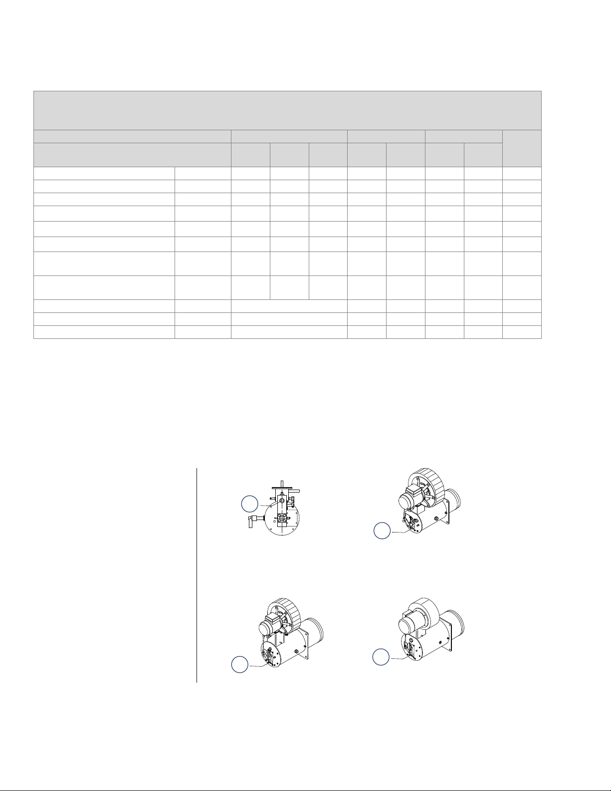
VALUPAK®-II
VALUPAK®-II 60
VALUPAK
®
-II 600
VALUPAK®-II 150
VALUPAK®-II 300
1) 1/2" NPT gas inlet
2) 3/4" NPT gas inlet
3) 1" NPT gas inlet
4) 1" NPt gas inlet
1
2
3
4
AVAILABLE VALUPAK®-II SIZES
Capacity and selection data in kW, 50 Hz operation
Gross heating value = 10.9 kWh/m
All figures are for balanced - 0 mbar - duct pressure
VALUPAK®-II size 60 [2] 150[2] 300[2]
Standard blower type
Maximum heat release
UHC
102
[3] kW (HHV) 40 60 80 225 185 290 360 558
UHC
122
Minimum heat release kW (HHV) 2 2 3 6 6 6 10 15
Turndown 20:1 30:1 27:1 38:1 31:1 48:1 36:1 37
Gas Q max.
Gas Q min.
Max. combustion air volume
Gas pressure at test connection
at maximum heat release
Gas pressure at inlet burner
at maximum heat release
m3 (st)/h
3
m
(st)/h
3
(st)/h
m
mbar 5.4 9 18 14.6 9.8 5 7.7 10.2
mbar 6.7 11.5 24 20.8 14.2 10.8 15.2 16.2
3.7 5.5 7.3 21.8 17.9 28.1 34.8 54
0.18 0.18 0.28 0.6 0.6 0.6 1 1.5
48 64 98 251 206 323 401 622
Blower motor 3x220-420x50 Hz kW 0.09 0.25 0.09 0.25 0.55 1.1
Weight kg n/a 24.2 20 29.7 31.5 47.6
Flame length
[4] m up to 0.4 (after sleeve) 1 1 1.3 1.5 1.6
3(st), d = 0.6
UMI
300
UMI
300
[1]
U/HC
122
UMI
300[5]
UMI
390
600
[1] Air pressure switches should be selected to have a setpoint ranging from (2-10) mbar-, with exception of the
VALUPAK®-II 60 burner with a capacity of 40 kW or 60 kW: setpoint ranging from (0.4 - 3) mbar
[2] Single phase blower motor available.
[3] Use of the standard round air inlet filter will cause a ± 15% capacity reduction. UMI blowers are not suited for filters.
Use of the standard VALUPAK®-II burner at 60 Hz will result in a higher max. capacity to which the gas pressures
need to be adapted.
[4] When firing in open air. Firing in a cross flow shortens flame.
[5] As an alternative blower U/HC 142 (0.18 kW)can be used , performance are same as with UMI300 blower
Protection: IP 54
32-00188-01 2 E - m - 6/18
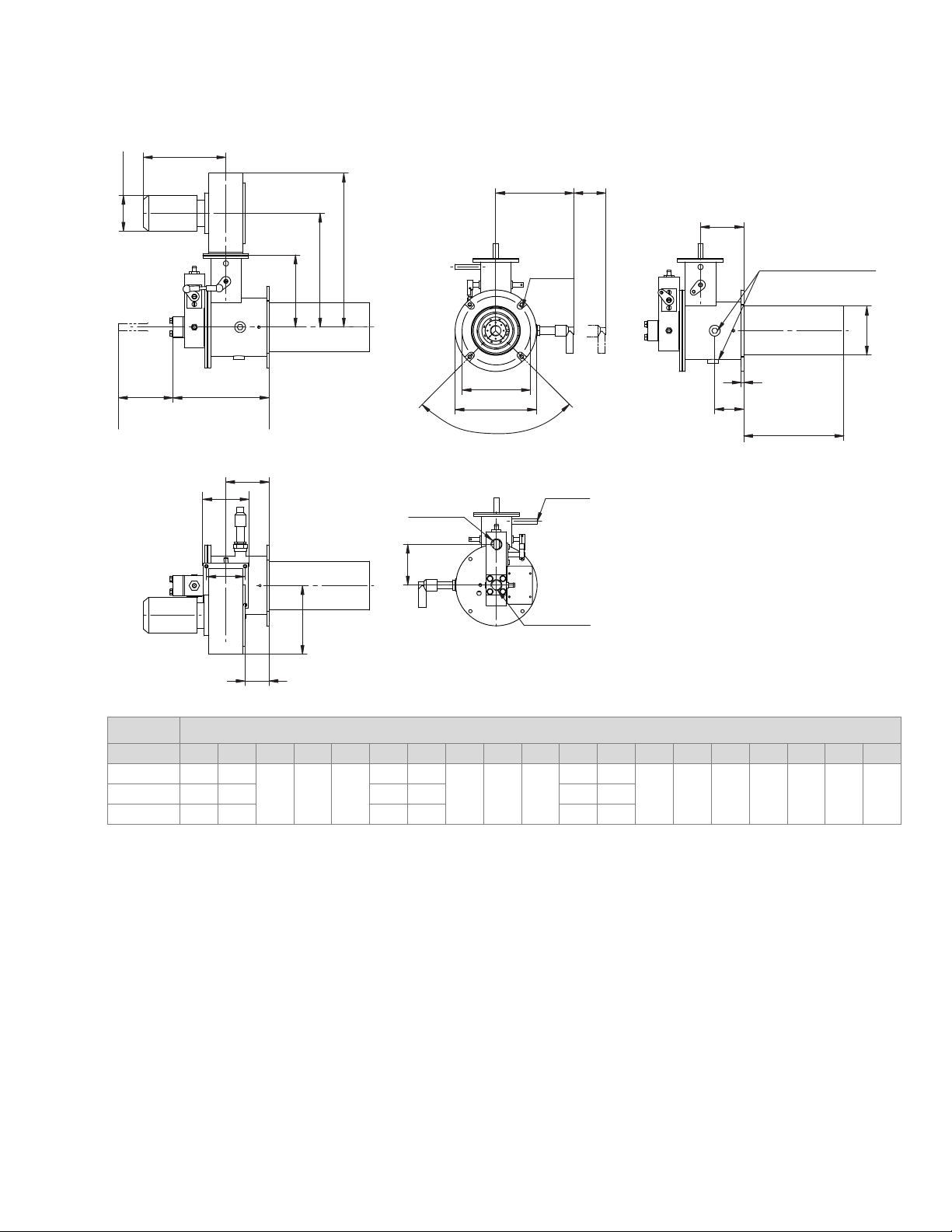
DIMENSIONS - VALUPAK®-II 60
G
ØF
A
B
C
M
4 x Ø12
VALUPAK®-II
N[2]
T
Plug
(Alternative SI position)
DIMENSIONS AND WEIGHTS
DE[1]
H
I
J
L
K
Rp 1/2"
Gas Inlet
T
ØO
ØP
4 x 90°
5
Q
R
Rc1/4"
1/2" NPT
Flame Rod
ØS
VP-II 60 Dimensions in mm unless stated otherwise
Blower A B C D E[1] ØF G H I J K L M N[2] ØO ØP Q ØS T
UHC 102 302 224
142 189 270
70,5 162
85 90 76
47 135
154 150 135 160 57 96 85UHC 122 442 331 112 208 42 179
UMI 300 539 389 120 247 41 248
[1] min. free space required for flame rod removal.
[2] min. free space required for SI removal.
E - m - 6/18 3 32-00188-01
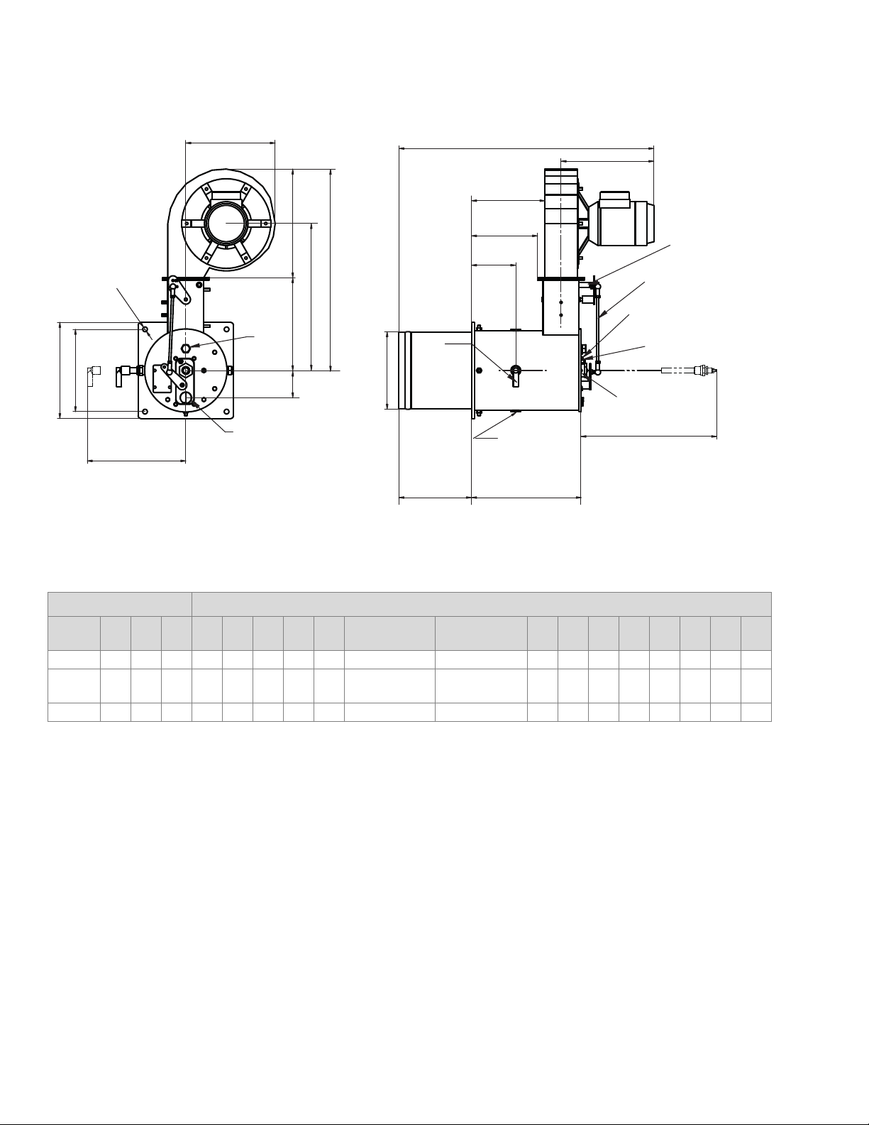
VALUPAK®-II
B
A
D
C
E
H
Gasinlet 1" NPT
Sight
glas
Q[1]
□F
□G
4 x Ø 13
Ø N
I
J
P
O
K
M L
R[2]
see note
(Plug for
alternatif
spark ignitor
position (4x90°))
NOTE : 4 possible
Spark Ignitor position
arrangements
L : Left side (standard)
R : Right side
U : Up (Fan side)
D : Down side.
AIR-GAS
linkage
1/4" NPT Air
switch connection
1/8" Gas pressure
test connection
1/8" Combustion air
pressure test connection
1/2" NPT flame
supervision
connection
Spark ignitor
1/2" NPT
DIMENSIONS - VALUPAK®-II 150, 300 & 600
VALUPA K®-II Dimensions in mm unless stated otherwise
Burner
size
A B C D E F G H I J K L M ØN O P Q[1] R[2]
150 481 248 300 332 182 184 214 55 637 257 123 275 150 160 165 186 240 500
300 553 248 300 404 254 226 264 75
600 549 248 287 403 262 286 318 85 805 293 131 379 200 262 227 250 325 560
[1] Minimum free space required for Spark Ignitor removal.
[2] Minimum free space required for Flamerod removal.
706 (UMI300)
733 (UMI390)
Dimensions with alternatives for UMI blowers available on request.
32-00188-01 4 E - m - 6/18
257 (UMI300)
284 (UMI390)
123 303 200 213 183 204 277 500
 Loading...