

Page 1
MasterLogic-200
High Speed Counter
2MLF-HO2A
2MLF-HD2A
10310000614 Printed in Korea
For more information on MasterLogic PLCs , contact your nearest Honeywell office
Australia
Honeywell Ltd.
Phone : (61) 2-9353-4500
Fax : (61) 2-9353-7677
China
Honeywell (Tianjin) Ltd. – Beijing
Phone: (86-10) 8458-3280
Fax: (86-10) 8458-3102
Honeywell (Tianjin) Ltd. – Shanghai
Phone: (86-21) 6237-0237
Fax : (86-21) 6237-3102
Indonesia
PT Honeywell Indonesia
Phone : (62) 21-535-8833
Fax : (62) 21-5367-1008
India
Honeywell Automation India Ltd.
Phone: (91) 20-5603-9400
Fax: (91) 20-5603-9800
Japan
Honeywell Inc.
Phone: (81)3-5440-1395
Fax: (81)3-5440-1368
South Korea
Honeywell Co., Ltd.
Phone : (82) 2-799-6114
Fax : (82) 2-792-9015
Malaysia
Honeywell Engineering Sdn Bhd.
Phone: (603) 7958-4988
Fax: (603) 7958-8922
New Zealand
Honeywell Ltd.
Phone: (64-9) 623-5050
Fax: (64-9) 623-5060
Philippines
Honeywell Systems Inc.
Phone: (63-2) 633-2830
Fax: (63-2) 638-4013
Singapore
Honeywell Pte Ltd.
Phone: (65) 6355-2828
Fax: (65) 6445-3033
Thailand
Honeywell Systems Ltd.
Phone: (662) 693-3099
Fax: (662) 693-3085
Taiwan
Honeywell Taiwan Ltd.
Phone: (886) 2-2245-1000
Fax: (886) 2-2245-3241
For Countries (SE Asia) Listed
below, call Honeywell Singapore
Office
Pakistan, Cambodia, Laos,
Myanmar, Vietnam and East Timor
For Countries Listed below,
call Honeywell India Office
Bangladesh, Nepal, and Sri Lanka
Honeywell Co., Ltd.
Honeywell Process Solutions
17F, Kukje Center Building, 191 Hangangro-2ga,
Yongsan-gu, Seoul 140-702, Korea
Tel : 82-2-799-6114 / Fax : 82-2-792-9015
Email : MasterLogic@Honeywell.com
10310000614 Printed in Korea
Safety Precautions
► Safety Precautions is for using the product safe and correct in order to prevent the accidents and
danger, so always follow the instructions.
► The precautions explained here only apply to the 2MLF-HO2A and 2MLF-HD2A module. For safety
precautions on the PLC system, refer to the MasterLogic-200 CPU User’s manual.
► The precautions are divided into 2 sections, ‘Warning’ and ‘Caution’. Each of the meanings is
represented as follows.
If violated instructions, it may cause death, fatal injury or considerable
loss of property.
If violated instructions, it may cause a slight injury or slight loss of
products
► The symbols which are indicated in the PLC and User’s Manual mean as follows
Gives warnings and cautions to prevent from risk of injury, fire, or malfunction.
Gives warnings and cautions to prevent from risk of electrical shock.
► Store this datasheet in a safe place so that you can take out and read whenever necessary.
Always forward it to the end user.
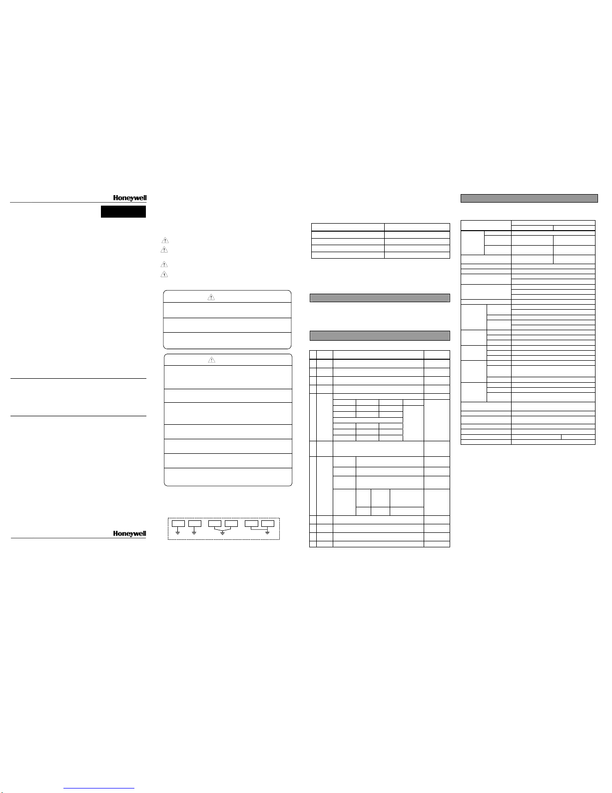
Precautions for use
► Do not install in any places other than PLC controlled place.
► Ensure that the FG terminal is grounded with class 3 grounding which is dedicated to the PLC.
Otherwise, it may cause disorder or malfunction of PLC
► Connect expansion connector correctly when expansion modules are needed.
► Do not detach PCB from the case of the module and do not modify the module.
► Turn off the power when attaching or detaching module.
► Cellular phone or walkie-talkie should be farther than 30cm from the PLC
► Input signal and communication line should be farther than minimum 100mm from a high-tension
line and a power line in order not to be affected by noise and magnetic field.
Before handling the product
Before using the product, read the datasheet and the User’s manual through to the end carefully in
order to use the product efficiently.
MasterLogic-200 User’s Manual
Name Code
2MLK-CPUH/CPUS User’s manual 10310000648
MasterLogic-200 Basic instruction manual 10310000649
MasterLogic-200 Software manual 10310000650
2MLF-HO2A/HD2A User’s manual 10310000618
High speed counter module designed for MasterLogic-200 series is used to count high
speed pulses from the encoder and there are two types of the pulse type 2MLF-HO2A
and the line drive type 2MLF-HD2A.
General specifications of MasterLogic-200 series are as specified below.
No Item Specifications
Related
specifications
1
Operating
temp.
0℃∼+55℃
2
Storage
temp.
-25℃∼+70℃
3
Operating
humidity
5∼95%RH, no dew allowed
4
Storage
humidity
5∼95%RH, no dew allowed
For discontinuous vibration
Frequency Acceleration Amplitude Number
10≤f< 57㎐ - 0.075mm
57≤f≤150㎐ 9.8m/s2(1G) -
For continuous vibration
Frequency Acceleration Amplitude
10≤f< 57㎐ - 0.035mm
5
Vibration
proof
57≤f≤150㎐ 4.9m/s2(0.5G) -
Each 10 times in
X,Y,Z directions
IEC 61131-2
6 Impact proof
* Max. impact acceleration: 147㎨(15G)
* Authorized time: 11㎳
* Pulse wave : Sign half-wave pulse (Each 3 times in X,Y,Z directions)
IEC 61131-2
Square wave
impulse noise
±1,500V -
Static electric
discharging
Voltage : 4kV(contact discharging)
IEC61131-2,
IEC61000-4-2
Radiation
electromagnetic
field noise
27 ~ 500MHz, 10 V/m
IEC61131-2,
IEC61000-4-3
Class Power module
Digital/
Analog I/O
communication interface
7 Noise proof
Fast Transient
/ burst noise
Voltage 2kV 1 kV
IEC61131-2,
IEC61000-4-4
8
Ambient
conditions
No corrosive gas or dust
Operating
height
2,000m or less
10
Pollution
level
2 or less
11 Cooling type Natural air cooling
Performance specifications of high speed counter module are as specified below.
Specification
Item
2MLF-H02A 2MLF-HD2A
Signal A-phase, b-phase
Input type
Voltage input
(Open Collector)
Differential input
(Line Drive):
Count
Input signal
Signal level
DC 5/12/24V
RS-422A Line Drive/
HTL LEVEL Line Drive
Max.count speed 200Kpps
500kpps
(HTL input is 250kpps)
Number of channels 2
Count range Signed 32-bit (-2,147,483,648 ~ 2,147,483,647)
Linear count (if 32-bit range exceeded, carry/borrow occurs)
Count type
(program setting)
Ring count (repeated count within setting range)
1-phase input
2-phase input
Input mode
(program setting)
CW/CCW input
Signal type
Voltage
Increasing/decreasing operation setting by B-phase input
1-phase input
Increasing/decreasing operation setting by program
2-phase input Automatic setting by difference in phase
A-phase input: increasing operation
Up/down
Setting
CW/CCW
B-phase input: decreasing operation
1-phaseinput 1/2 multiplier (program setting)
2-phaseinput 1/2/4 multiplier (Program setting)
Multiplier
function
CW/CCW
1-multiplier
Sign Preset command input, additional function command input
Sign level DC 5V/12V/24V(select terminal)input type
Control input
Sign type
Voltage
Output points 2-point/channel(for each channel): terminal output available
Type
Select single-compared(>, >=, =, =<, <) or section
compared output (included or excluded) (program setting)
External output
Output type
Open collector output(Sink)
Input sign
A-phase, B-phase, Preset command, additional function
command
Output sign OUT1, OUT2
Function to
display
operation
status
Operation
status
Module Ready, A/B phase pulse input status
Count enable
To be set through program
(count available only in enable status)
Preset function To be set through terminal or program
Additional functions
(program setting)
Count clear, count latch,
Section count (time setting value: 1~60000ms)
M t f i t f
Terminal 40-pin connector
I/O Occupied points
Fixed point assignment
: 64,
Variable point assignment
: 16
Internal consumed current
270 mA 270 mA
Weight
(g)
90g
1. Introduction
2. General specifications
3. Performance specifications
Caution
Warning
► Before wiring the PLC, ensure to check the rated voltage and
terminal arrangement for the module before wiring work.
Risk of electric shock, fire and malfunction
►
Tighten the screw of terminal block with the specified torque range.
Risk of fire and electric shock if the terminal screw looses.
► Use the PLC in an environment that meets the general
specifications contained in this datasheet.
Risk of electrical shock, fire, erroneous operation and deterioration of the PLC.
►
Be sure that external load does not exceed the rating of output module.
Risk of fire and erroneous operation.
► Do not use the PLC in the environment of direct vibration
Risk of electrical shock, fire and erroneous operation.
► Do not disassemble, repair or modify the PLC.
Risk of electrical shock, fire and erroneous operation.
► When disposing of PLC and battery, treat it as industrial waste.
Risk of poisonous pollution or explosion.
Caution
PLC Others
< Best >
PLC Others PLC Others
< Good > < Bad >
X Do not contact the terminals while the power is applied.
Risk of electric shock and malfunction.
X Do not drop or insert any metallic object into the product.
Risk of fire, electric shock and malfunction.
X Do not charge, heat, short, solder and break up the battery.
Risk of injury and fire by explosion and ignition.
Warning
DATASHEET
Page 2
1. Count input specifications
Specification
Item
Voltage input type Differential type
Input voltage
24V DC
(17.0V ~ 26.4V)
12V DC
(9.8V ~ 13.2V)
5V DC
(4.5V~5.5V)
Line Driver
Input current
7~11 mA 7~11 mA 7~11mA
ON guaranteed
voltage( min.)
17.0 V 9.8V 4.1V
OFF guaranteed
voltage (max.)
4.5V 3.0V 1.7V
RS-422A Line Driver
HTL LEVEL Line Driver
2. Preset/Gate input specifications
Item Preset/Gate input
Input voltage
24V DC 12V DC 5V DC
Input current
3~6 mA 3~6 mA 3~6 mA
ON guaranteed voltage
15.2 V 10.8V 4.1V
OFF guaranteed voltage
3.2V 2.5V 1.4V
On delayed time
1ms or less
Off delayed time
1ms or less
3. Transistor output (sink) specifications
Item Specification
Rated output
DC 24V, 100 mA/point
Leaked current
0.1 mA
or less
Saturated area voltage
1.3 V
or less
On delayed time
0.1 ms
or less
Off delayed time
0.1 ms
or less
5.1 2MLF-HO2A/HD2A
No. Designation
Description
∅
A
A-phase pulse input
∅
B
B-phase pulse input
P
External preset input
G
External gate input
OUT0
OUT0 compared output
OUT1
OUT1 compared output
①
LED
display
READY
Ready signal
② I/O connector
Terminal for I/O with external device
5.2 Specifications of interface with external devices
Designations of signals Pin
assignment
Pin/Ch
2MLF-HO2A 2MLF-HD2A
1 A12V A-phase DC12V input AⅠ-_ AI- input (TTL LEVEL input)
2 A24V A-phase DC24V input AⅠ+ AI+ input (TTL LEVEL input)
3 A_C A-phase COM terminal AⅡ-_ AII- input (HTL LEVEL input)
4 A5V A-phase DC5V input AⅡ+ AII+ input (HTL LEVEL input)
5 B12V B-phase DC12V input BⅠ-_ BI- input (TTL LEVEL input)
6 B24V B-phase DC24V input BⅠ+ BI+ input (TTL LEVEL input)
7 B_C B-phase COM terminal BⅡ-_ BII- input (HTL LEVEL input)
8 B5V B-phase DC5V input BⅡ+ BII+ input (HTL LEVEL input)
9 P12V Preset DC12V input P12V Preset DC12V input
10 P24V Preset DC24V input P24V Preset DC24V input
11 P_C Preset COM terminal P_C Preset COM terminal
12 P5V Preset DC5V input P5V Preset DC5V input
13 G12V Gate DC12V input G12V Gate DC12V input
14 G24V Gate DC24V input G24V Gate DC24V input
15 G_C Gate COM terminal G_C Gate COM terminal
16
C
H
0
G5V Gate DC5V input G5V Gate DC5V input
17 A12V A-phase DC12V input AⅠ-_ AI- input (TTL LEVEL input)
18 A24V A-phase DC24V input A +Ⅰ AI+ input (TTL LEVEL input)
19 A_C A-phase COM terminal AⅡ-_ AII- input (HTL LEVEL input)
20 A5V A-phase DC5V input A +Ⅱ AII+ input (HTL LEVEL input)
21 B12V B-phase DC12V input BⅠ-_ BI- input (TTL LEVEL input)
22 B24V B-phase DC24V input B +Ⅰ BI+ input (TTL LEVEL input)
23 B_C B-phase COM terminal BⅡ-_ BII- input (HTL LEVEL input)
24 B5V B-phase DC5V input B +Ⅱ BII+ input (HTL LEVEL input)
25 P12V Preset DC12V input P12V Preset DC12V input
26 P24V Preset DC24V input P24V Preset DC24V input
27 P_C Preset COM terminal P_C Preset COM terminal
28 P5V Preset DC5V input P5V Preset DC5V input
29 G12V Gate DC12V input G12V Gate DC12V input
30 G24V Gate DC24V input G24V Gate DC24V input
31 G_C Gate COM terminal G_C Gate COM terminal
32
C
H
1
G5V Gate DC5V input G5V Gate DC5V input
33 OUT1 Compared output OUT1 OUT1 Compared output OUT1
34
C
H
0
OUT0 Compared output OUT0 OUT0 Compared output OUT0
35 OUT1 Compared output OUT1 OUT1 Compared output OUT1
36
C
H
1
OUT0 Compared output OUT0 OUT0 Compared output OUT0
37 24V 24V 24V 24V
38 24V 24V 24V 24V
39 24G 24V COM 24G 24V COM
40 24G 24V COM 24G 24V COM
1) Do not drop or give impact on the product.
2) Do not detach PCB from the case, it may cause malfunction.
3) During wiring or other work, do not allow any wire chips get inside the product.
4) Switch off the external power before mounting or removing the module and
the cable.
5) Ensure to turn off the drive device for detaching or inserting the cable
1) Ensure to separate the power line and the signal line during wiring.
2) Wire the cable as short as possible.
3) Use the separate cable between the AC power line and the signal line not to be
affected by the AC surge or inductive noise.
4) Use the stable external power source for DC24V.
5) Place the cable away from heat and avoid direct contact with oil for long. It may
cause malfunction, short or damage.
8.1 Input setting area
Internal memory
CH0 CH1
Details
00 25 Select counter type
01 26 Select pulse input type
02 27
03 28
Set preset value
04 29
05 30
Ring count min.value
06 31
07 32
Ring count max.value
08 33 Select OUT0 type
09 34 Select OUT1 type
10 35
11 36
OUT0 compared based value(single-compared)/ min.setting value
(section compared)
12 37
13 38
OUT0 compared based value max. setting value(section- compared)
14 39
15 40
OUT1 compared based value(single-compared)/
min.setting value (section-compared)
16 41
17 42
OUT1 compared based value max. setting value(section-compared)
50 50 Define output status when PLC CPU stops (CH0, CH1 common)
18 43 Select additional function type
19 44 Section count time setting or Revolutions per hour count time setting
20 45 Revolutions per hour function, pulses per revolution input
21 46 Select frequency displayed mode
8.2. Output setting area
Internal memory
CH0 CH1
Details
Uxy.02 Uxy.12
Uxy.03 Uxy.33
Present count value
Uxy.04 Uxy.44
Uxy.05 Uxy.15
Latch count value
Uxy.06 Uxy.16
Uxy.07 Uxy.17
Section count value
Uxy.08 Uxy.18
Uxy.09 Uxy.19
Input frequency value
Uxy.10 Uxy.20
Uxy.11 Uxy.21
Revolutions per hour value
PLC <- HS counter PLC -> HS counter
Ch
Address Details Address Details
Uxy.00.0
Increasing/decreasing count
sign
Uxy.23.0 Count operation enabled sign(Level)
Uxy.00.1 External input preset flag Uxy.23.1 Preset enabled sign(edge)
Uxy.00.2 - Uxy.23.2 Increasing/decreasing count setting sign (Level)
Uxy.00.3 Carry sign Uxy.23.3 Additional function use command(edge, level)
Uxy.00.4 Borrow sign Uxy.23.4 Compared function use command(Level)
Uxy.00.5
Flag during additional function
Uxy.23.5
Compared output external terminal enabled
Uxy.00.6 OUT0 output sign Uxy.23.6 OUT0 identical reset sign(Edge)
Uxy.00.7 OUT1 output sign Uxy.23.7 OUT1 identical reset sign(Edge)
Uxy.00.8 - Uxy.23.8 Uxy.00.9 - Uxy.23.9 Uxy.00.A - Uxy.23.A Carry/Borrow reset sign(Edge)
Uxy.00.B - Uxy.23.B Preset external input setting sign
Uxy.00.C - Uxy.23.C
Command of additional function use
Uxy.00.D - Uxy.23.D External input preset flag reset sign
Uxy.00.E CH0 error flag Uxy.23.E -
0
Uxy.00.F Module Ready Uxy.23.F -
Uxy.01.0
Increasing/decreasing count
sign
Uxy.24.0 Count operation enabled sign(Level)
Uxy.01.1 External input preset flag Uxy.24.1 Preset enabled sign(edge)
Uxy.01.2 - Uxy.24.2 Increasing/decreasing count setting sign (Level)
Uxy.01.3 Carry sign Uxy.24.3 Additional function use command(edge, level)
Uxy.01.4 Borrow sign Uxy.24.4 Compared function use command(Level)
Uxy.01.5
Flag during additional function
operation
Uxy.24.5
Compared output external terminal enabled
sign(Level)
Uxy.01.6 OUT0 output sign Uxy.24.6 OUT0 identical reset sign(Edge)
Uxy.01.7 OUT1 output sign Uxy.24.7 OUT1 identical reset sign(Edge)
Uxy.01.8 - Uxy.24.8 Uxy.01.9 - Uxy.24.9 Uxy.01.A - Uxy.24.A Carry/Borrow reset sign(Edge)
Uxy.01.B - Uxy.24.B Preset external input setting sign
Uxy.01.C - Uxy.24.C
Command of additional function use
Uxy.01.D - Uxy.24.D External input preset flag reset sign
Uxy.01.E CH0 error flag Uxy.24.E -
1
Uxy.01.F Module Ready Uxy.24.F -
Unit : ㎜
1) 2MLF-HO2A/HD2A
4. External Input/output specifications
5. Designations of Parts
6. Handling precaution
7. Wiring
8. Internal memory (Parameter setting)
9. Input / Output signals
10. External dimension
①
DC24V
P12V P24V
P_C P5V
G12V G24V
G_C G5V
OUT1 OUT0
OUT1 OUT0
24V 24V
24G 24G
CH0
CH0
CH1
P12V P24V
P_C P5V
G12V G24V
G_C G5V
CH1
P12V P24V
P_C P5V
G12V G24V
G_C G5V
OUT1 OUT0
OUT1 OUT0
24V 24V
24G 24G
CH0
CH0
CH1
P12V P24V
P_C P5V
G12V G24V
G_C G5V
CH1
DC24V
A12V
A24V
P12V P24V
P_C P5V
G12V G24V
G_C G5V
OUT1 OUT0
OUT1 OUT0
24V 24V
24G 24G
CH0
CH0
CH1
P12V P24V
P_C P5V
G12V G24V
G_C G5V
CH1
P12V P24V
P_C P5V
G12V G24V
G_C G5V
OUT1 OUT0
OUT1 OUT0
24V 24V
24G 24G
CH0
CH0
CH1
P12V P24V
P_C P5V
G12V G24V
G_C G5V
CH1
A_C A5V
B12V B24V
B_C
B5V
A12V A24V
A_C
A5V
B12V B24V
B_C B5V
XGF-HO2A
RDY
CH0
CH1
φA φB P G
O0
O1
AII- AII+
BII- BII+
AII- AII+
BII- BII+
AI- AI+
BI- BI+
AI- AI+
BI- BI+
XGF-HD2A
RDY
CH0
CH1
φA φB P G O0
O1
DC24V
P12V P24V
P_C P5V
G12V G24V
G_C G5V
OUT1 OUT0
OUT1 OUT0
24V 24V
24G 24G
CH0
CH0
CH1
P12V P24V
P_C P5V
G12V G24V
G_C G5V
CH1
P12V P24V
P_C P5V
G12V G24V
G_C G5V
OUT1 OUT0
OUT1 OUT0
24V 24V
24G 24G
CH0
CH0
CH1
P12V P24V
P_C P5V
G12V G24V
G_C G5V
CH1
DC24V
P12V P24V
P_C P5V
G12V G24V
G_C G5V
OUT1 OUT0
OUT1 OUT0
24V 24V
24G 24G
CH0
CH0
CH1
P12V P24V
P_C P5V
G12V G24V
G_C G5V
CH1
P12V P24V
P_C P5V
G12V G24V
G_C G5V
OUT1 OUT0
OUT1 OUT0
24V 24V
24G 24G
CH0
CH0
CH1
P12V P24V
P_C P5V
G12V G24V
G_C G5V
CH1
DC24V
A12V
A24V
P12V P24V
P_C P5V
G12V G24V
G_C G5V
OUT1 OUT0
OUT1 OUT0
24V 24V
24G 24G
CH0
CH0
CH1
P12V P24V
P_C P5V
G12V G24V
G_C G5V
CH1
P12V P24V
P_C P5V
G12V G24V
G_C G5V
OUT1 OUT0
OUT1 OUT0
24V 24V
24G 24G
CH0
CH0
CH1
P12V P24V
P_C P5V
G12V G24V
G_C G5V
CH1
A_C A5V
B12V B24V
B_C
B5V
A12V A24V
A_C
A5V
B12V B24V
B_C B5V
XGF-HO2A
RDY
CH0
CH1
φA φB P G
O0
O1
AII- AII+
BII- BII+
AII- AII+
BII- BII+
AI- AI+
BI- BI+
AI- AI+
BI- BI+
XGF-HD2A
RDY
CH0
CH1
φA φB P G O0
O1
DC24V
A12V
A24V
P12V P24V
P_C P5V
G12V G24V
G_C G5V
OUT1 OUT0
OUT1 OUT0
24V 24V
24G 24G
CH0
CH0
CH1
P12V P24V
P_C P5V
G12V G24V
G_C G5V
CH1
P12V P24V
P_C P5V
G12V G24V
G_C G5V
OUT1 OUT0
OUT1 OUT0
24V 24V
24G 24G
CH0
CH0
CH1
P12V P24V
P_C P5V
G12V G24V
G_C G5V
CH1
A_C A5V
B12V B24V
B_C
B5V
A12V A24V
A_C
A5V
B12V B24V
B_C B5V
XGF-HO2A
RDY
CH0
CH1
φA φB P G
O0
O1
AII- AII+
BII- BII+
AII- AII+
BII- BII+
AI- AI+
BI- BI+
AI- AI+
BI- BI+
XGF-HD2A
RDY
CH0
CH1
φA φB P G O0
O1
AII- AII+
BII- BII+
AII- AII+
BII- BII+
AI- AI+
BI- BI+
AI- AI+
BI- BI+
XGF-HD2A
RDY
CH0
CH1
φA φB P G O0O1O0
O1
②
CH1
OUT1 OUT0
24G 24G
24V 24V
+
-
XGF-HD2A
DC24V
A- A+
CH1
CH0
G12V
GCOM
G24V
G5V
P12V P24V
PCOM P5V
PCOM P5V
P12V P24V
CH0
OUT1
GCOM
G12V
OUT0
G5V
G24V
O0 O1G
RDY
PØA
CH1
CH0
XGF-HD2A
ØB
A- A+
B+B-
B+B-
A+
A-
B+B-
B+B-
A+A-
LINEDRIVE
-0.2
0
-0.2
0
27
98
90±0.1
1
3
5
7
9
11
13
15
17
19
21
23
25
27
29
31
33
35
37
39
2
4
6
8
10
12
14
16
18
20
22
24
26
28
30
32
34
36
38
40
 Loading...