

Page 1

MasterLink Software Application User's Guide
Version 3.0 | July 2020
Patch Release to Support MIWI350 R110.1
Honeywell Process Solutions | Mercury Instruments
1280 Kemper Meadow Drive,
Cincinnati, OH 45240
855 251-7065 – United States & Canada | 302 669-4253 – Outside the United States
MI-TAC-Support@Honeywell.com | www.honeywellprocess.com
Page 2

Copyright July 2020. Honeywell Process Solutions. All rights reserved.
Information in this document is subject to change without notice. The software described in
this document is furnished under a license agreement or non-disclosure agreement. The
software may be used or copied only in accordance with the terms of those agreements. No
part of this publication may be reproduced, stored in a retrieval system, or transmitted in
any form or any means electronic or mechanical, including photocopying and recording for
any purpose other than the purchaser's personal use without the written permission of
Honeywell Process Solutions.
For technical assistance, email at MI-TAC-Support@Honeywell.com.
Page 3

CONTENTS
1 About MasterLink 1
1.1 Features 1
1.2 Security Considerations 2
1.1 Supported Device Functionality 3
1.2 Supported File formats and extensions 5
2 Installation 7
2.1 Before you install 7
2.2 Interoperability with SuiteSQL 8
2.3 Silent Installation 8
2.4 MasterLink Client Installation with SQL Server 9
2.4.1 Installing MasterLink with remote SQL Server 15
2.5 Installing MasterLink with SQLite 20
2.6 Upgrading MasterLink with SQLite/ SQL Server 26
2.7 Post Installation Steps 27
3 MasterLink User Interface 29
3.1 Getting Started 29
3.1.1 User Creation and Activation Process 29
3.1.1.1 Site Administrator Creation 29
3.1.1.2 Creating Users 30
3.1.1.3 User Registration 30
3.1.1.4 Forgot Password 32
3.2 Sites 33
3.2.1 Add Site 34
3.2.2 Connecting to a Site 37
3.2.3 Direct Connect 39
3.3 Dashboard 40
3.3.1 User Interface 43
3.3.2 Instrument Data 47
3.3.3 Alarms 48
3.3.4 Configuration Check 50
3.3.5 Time Sync 52
3.3.6 Firmware Update 53
3.3.7 Data Transfer 55
3.3.8 Instrument or Modem Power 57
3.3.9 Update User Account 61
3.3.10 Change Password 62
3.4 View and Edit 63
3.4.1 Configure by Group 63
3.4.2 Configure by Item 66
3.4.3 Send Item File 69
3.4.4 Logging Configuration 71
3.4.5 Manage User Table 74
3.4.6 Manage Shortlist 76
3.4.7 Manage AGA-8 77
3.5 Calibrate 78
3.5.1 Pressure Calibration P1 78
3.5.2 Pressure Calibration P2 86
3.5.3 Pressure Calibration P3 86
3.5.4 Temperature Calibration 88
Page 4

3.5.5 Calibration Parameter 94
3.6 Read Data 95
3.6.1 Item File 96
3.6.2 Audit Trail 100
3.6.2.1 Audit Trail Graphs 105
Line Graphs 107
Circular Graphs 110
3.6.3 Alarm Logs 113
3.6.4 Event Logs 116
3.6.5 Diagnostic Logs 119
3.6.6 Cellular Logs 121
3.6.7 Shortlist 123
3.6.8 Activity Log 125
3.6.9 Item Reference CSV Export 127
3.7 Live Data 128
3.8 Administer 134
3.8.1 Activity Log - Purge 134
3.8.2 Export Instrument Data 137
3.8.3 Import Instrument Data 141
3.8.4 Item Template Configuration 146
3.8.5 Clear Logs 149
3.9 Settings 150
3.9.1 Communications Setup 150
3.9.2 Time-Sync Properties 153
3.9.3 Auto Download Settings 154
3.9.4 Device Properties 155
3.10 Security and User Management 156
3.10.1 User Configuration 157
3.10.1.1 Passkey Generation 159
3.10.2 User Roles 161
CONTENTS
4 Updates and Upgrades 163
4.1 EC 350/ ERX 350 Firmware Update 163
4.2 CloudLink Modem Firmware Update 164
4.3 Upload CloudLink Modem Certificates 165
4.4 Legacy Devices Firmware Upgrades 167
5 Glossary 169
5.1 Troubleshooting scenarios 171
Page 5

1 About MasterLink
1 About MasterLink
MasterLink application provides a single software package to configure, calibrate and access data
from gas volume correctors. The software’s intuitive dashboard enables users to quickly determine
the overall health status of instruments. Employing standardized terminology, it is now an easy
task to configure and calibrate instruments, import data, and generate reports and graphs, thereby
eliminating time-consuming manual effort.
This software employs a dashboard based design philosophy enabling users to get a one-shot
status of connected devices. A gas industry first, the software can connect to the device using a
choice of short- range wireless communication protocols. The dashboard displays information
about alarms, battery voltage, audit trail, configuration integrity, firmware status, time sync and
live data. This helps the user understand the current condition of the connected device from a hol-
istic point of view.
MasterLink software addresses the increasing adoption of mobile devices for functions like check-
ing the health of field devices, downloading reports, instrument calibration and other activities
once performed exclusively on a laptop. It offers versatile wireless connectivity and is compatible
with the latest versions of both iOS and Android operating systems.
1.1 Features
MasterLink allows users to:
Define dashboard data (auto) download settings
Secure critical site data
Enable SSL encrypted communication with site Over the Air (OTA)
View / Edit item parameters of a connected device
Provides a wizard based calibration approach
Generate reports such as:
Item report - Item Report by Group, Site Report and Calibration Report
Audit Trail report (Plot graph over Audit Trail data)
Alarm Log report
Event Log report
Diagnostic Log report
Cellular Log report
Short List report
Activity Log report
Item Reference CSV Export
Capture live data and plot graphs
Honeywell | 1
Page 6

Perform Database Administrative tasks such as
Activity Log Purge
Import/Export site or instrument data
Item Template Configuration
Clear Logs
Configure settings
Communication Setup
Time Sync Properties
Auto Download Settings for Dashboard
Device Properties
Email Options
Perform role based user administration for MasterLink
1 About MasterLink
Administer access privileges for device level functions by sending user table
Perform offline log-in configuration and send to instrument when connected
Perform instrument and modem firmware updates
1.2 Security Considerations
It is recommended to use the CloudLink modem in integrated mode with EC 350 for better
security during pairing
For data protection, it is recommended to provide full privileges to the Pro-
gramData\Honeywell\MasterLink folder only to appropriate MasterLink users
It is recommended to keep the PC used for MasterLink updated with the security patches
released by the respective platforms
It is also recommended to enable SSL for secure communication with MasterLink.
Its highly recommended to Install latest operating system security patches on the
machine where ML is installed.
Do not share MLK file with any unintended user
Honeywell | 2
Page 7

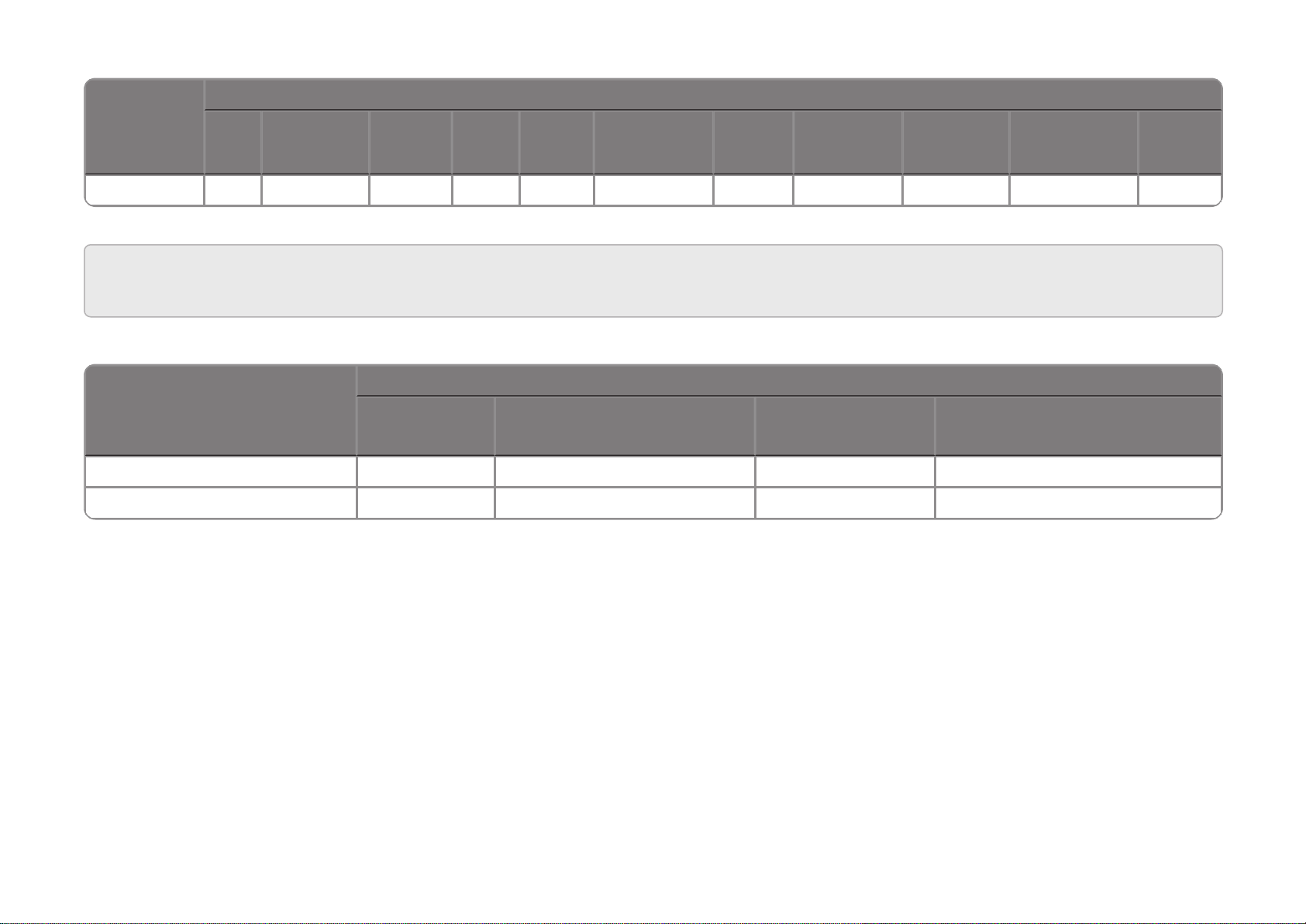
1.1 Supported Device Functionality
*CL = CloudLink, PA = Pulse Accumulator, TC = Turbo Corrector
EC 350 CL*EC350 +CLPA* CNI4
Mini-
Max
ERX TCI
Mini-
AT
TC* Accutest ERX 350
ERX 350 +
CL
Mini
Turbo
Monitor
PT Mod-
bus
ER ECAT
Item Report
ü ü ü ü ü ü ü ü ü ü ü ü ü ü ü ü ü ü
Audit Report
ü û ü ü ü ü ü ü ü ü ü ü ü û û û ü ü
Alarm Report
ü ü ü û ü ü û û ü ü ü ü ü û û û û ü
Event Report
ü ü ü û ü ü û û ü ü ü ü ü û û û û ü
Diagnostic Report
û ü ü û ü û û û û û û û ü û û û û û
Cellular Report
û ü ü û ü û û û û û û û ü û û û û û
Shortlist Report
ü ü ü ü ü ü ü ü ü ü ü ü ü ü ü ü ü ü
Activity Report
ü ü ü ü ü ü ü ü ü ü ü ü ü ü ü ü ü ü
Send Log
Configuration
ü û ü û û û û û û û û ü ü û û û û û
Change
Instrument
Access Code
û û û ü û ü ü ü ü ü ü û û ü ü ü ü ü
Send User Table
ü ü ü û ü û û û û û û ü ü û û û û û
Send Item File
ü ü ü ü ü ü ü ü ü ü ü ü ü ü ü ü ü ü
Config Check
Template
ü û ü ü ü ü ü ü ü ü ü ü ü ü ü ü ü ü
P1 Calibration
ü û ü û û ü ü û ü ü ü ü ü ü û û ü ü
P2 Calibration
ü û ü û û û ü û ü ü ü ü ü û û û ü û
P3 Calibration
û û û û û û ü û û û û û û û û û û û
Temperature
ü û ü û û ü ü ü ü ü ü ü ü ü û û ü ü
Page 8

*CL = CloudLink, PA = Pulse Accumulator, TC = Turbo Corrector
EC 350 CL*EC350 +CLPA* CNI4
Mini-
Max
ERX TCI
Mini-
AT
TC* Accutest ERX 350
ERX 350 +
CL
Mini
Turbo
Monitor
PT Mod-
bus
ER ECAT
Calibration
Firmware
Download
ü ü ü û ü û û û û û û ü ü û û û û û
Config By Item Or
Group
ü ü ü ü ü ü ü ü ü ü ü ü ü ü ü ü ü ü
Audit Trail Edit
ü û ü ü ü ü ü ü ü ü ü ü ü û û û ü ü
Shut Down Device
ü û ü ü ü ü ü ü ü ü ü ü ü ü ü ü ü ü
Live Data Graph
ü û ü û û ü ü ü ü ü ü ü ü ü û û ü ü
Administer Data
ü ü ü ü ü ü ü ü ü ü ü ü ü ü ü ü ü ü
EVC Firmware
Download
ü û ü ü ü ü ü ü ü ü ü ü ü ü ü ü ü ü
Certificate Upload
û ü ü û ü û û û û û û û ü û û û û û
Modem Firmware
Download
û ü ü û ü û û û û û û û ü û û û û û
Time Sync
ü ü ü ü ü ü ü ü ü ü ü ü ü û û û ü ü
Write Items
ü ü ü ü ü ü ü ü ü ü ü ü ü ü ü ü ü ü
Active Alarms
ü ü ü ü ü ü ü ü ü ü ü ü ü ü ü û ü ü
User
Management
ü ü ü ü ü ü ü ü ü ü ü ü ü ü ü ü ü ü
Generate Reports
ü ü ü û ü ü ü ü ü ü ü ü ü ü ü ü ü ü
EVC Reset Battery
ü ü ü û û û û ü û û û ü ü û û û û û
Page 9

1.2 Supported File formats and extensions
FILE FORMAT EXTENSION
Item
File
Item Tem-
plate File
Firmware
File
User
Table
Shortlist
file
Logging Con-
figuration
Audit
Graphs
Live Graph
Setting
Live Graph
Values
Shortlist file with
value
Certificate
file
EC 350 IE3 TE3 BIN UTE CE3 LC AGS LGS LGV KE3
CloudLink
Modem
ICL TCL BIN UTE CCL KCL PEM
EC 350 +
CloudLink
ECL TEL BIN UTE CEL LC AGS LGS LGV KEL
Pulse Accumulator
IPA TPA MMX CPA KPA
CNI4 INI4 TNI4 MMX/BIN UTE SNI4 KNI4
Mini-Max IMX TMX MMX CMX LGS LGV KMX
ERX IEX TEX MMX CEX LGS LGV KEX
TCI ITC TTCI TCA CTC LGS LGV KTC
Mini-AT IMA TMA TXT CMA LGS LGV KMA
Turbo Corrector
ITT TTT CTT LGS LGV KTT
Accutest ITA TTA CTA LGS LGV KTA
ERX 350 IER3 TER3 BIN UTE CER3 LCER3 LGS LGV KER3
ERX 350 +
CloudLink
IER3L TER3L BIN UTE CER3L LCER3 AGS LGS LGV KER3L
Mini IMN TMN CMN LGV KMN
Turbo Monitor ITB TTB TBX/T8X CTB KTB
PT Modbus IPTC TPTC PTX CPTC KPTC
ER IER TER CER LGS LGV KER
Page 10
FILE FORMAT EXTENSION
Item
File
Item Tem-
plate File
Firmware
File
User
Table
Shortlist
file
Logging Con-
figuration
Audit
Graphs
Live Graph
Setting
Live Graph
Values
Shortlist file with
value
Certificate
file
ECAT IAT TAT CAT LGS LGV KAT
Note: While upgrading R500 to R510, the file format extensions of CloudLink Modem and EC 350 + CloudLink Integrated device are to be changed as
FILE FORMAT EXTENSION
Item File Item Template File Shortlist file
Shortlist file with value
CloudLink Modem ICL TCL CCL KCL
EC 350 + CloudLink ECL TEL CEL KEL
below.
Page 11

2 Installation
Component Requirement
CPU Quad Core and above
RAM 8 GB and above
Disk Space 80 GB and above
Operating System
Microsoft Windows 2008 Standard Edition 32 bit
Microsoft Windows 2008 Standard Edition 64 bit
Microsoft Windows 2008 R2 Standard Edition 32 bit
Microsoft Windows 2008 R2 Standard Edition 64 bit
Windows Server 2012 – SP1 (Standard, Essentials) : 64 bit
Windows Server 2012 R2 –SP1 (Standard, Essentials) : 64 bit
Windows Server 2016 (Standard, Essentials) : 64 bit
Database Server
SQL Server 2008 R2 (Standard, Enterprise) : 32 bit
SQL Server 2012 (Standard, Enterprise) : 32 bit
SQL Server 2014 (Standard, Enterprise) : 32 bit
SQL Server 2008 R2 (Standard, Enterprise) : 64 bit
SQL Server 2012 (Standard, Enterprise) : 64 bit
SQL Server 2014 (Standard, Enterprise) : 64 bit
SQL Server 2016 (Standard, Enterprise) : 64 bit
SQL Server 2017 (Standard, Enterprise) : 64 bit
2 Installation
This chapter describes the installation of MasterLink software.
2.1 Before you install
Here are the recommended system specifications:
Database Server Configuration
Note: If you are using a database instance on your network, you need to have domain user per-
mission.
Honeywell | 7
Page 12

Client Configuration
Component Requirement
CPU Dual Core and above
RAM 4 GB and above
Disk Space 40 GB and above
Operating System
Windows 7 – SP2 / Convenience rollup (Professional, Enterprise, Ultimate) :
32bit, 64 bit
Windows 8 – (Core, Pro, Enterprise) : 32bit, 64 bit
Windows 8.1 – (Core, Pro, Enterprise) : 32bit, 64 bit
Windows 10 – (latest build 2 months before release) : 32bit, 64 bit
Windows Vista Standard Edition 32 bit
Android
Android OS 4.3x, 4.4.0-4.4.4, 5.0.0-5.0.2, 5.1.x, 6.0
RAM: 1 GB onwards Memory: 8 GB onwards
Processor Speed: Dual-core 1 GHz onwards
Communication BLE compatible
General availability of Mail Client required
iOS
OS 7.1.x, 8.4.x, 9.1.x, 10.1.x
Memory: 8 GB onwards
Screen Size: 3.5 inches onwards
RAM: 1 GB onwards
Communication BLE capability
General availability of Mail Client required
Mobile Recommendations
2 Installation
2.2 Interoperability with SuiteSQL
MasterLink application can coexist with Suite SQL.
New MasterLink can be used with either SQL database Server or SQLite database.
If a single data source is preferred with an existing MasterLink SQL installation, please choose SQL
Server as a database option during installation.
2.3 Silent Installation
TO INSTALL SQL LITE IN SILENT MODE:
Command to Install the exe
Msiexec /i “<Path to MasterLink515.1exe>” /S /v”/qn DBTYPE=2 INSTALLDIR= <Path to Install>”
Honeywell | 8
Page 13

2 Installation
Note:
INSTALLDIR is an optional argument, if it is not passed, by default it will get installed to
“C:\Program Files(x86) \Honeywell\MasterLink”
There is no space between /v and “
/S is case sensitive and it must be upper case.
DBTYPE is passed as empty, then SQLite DB will be installed
Example:
“C:\E569427___tanmay\RMG (\ML\build\MasterLinkR515.1.exe” /S /v”/qn DBTYPE=2 INSTALLDIR-
R=\”C:\Program Files(x86)\Honeywell\MasterLink\””
Path to Masterlink.exe - C:\E569427___tanmay\RMG (\ML\build\MasterLinkR515.1.exe
Path to Install - \”C:\Program Files(x86)\Honeywell\MasterLink\””
TO INSTALL SQL DB SERVER IN SILENT MODE:
Command to Install the exe
Msiexec /i “<Path to MasterLink515.1exe>” /S /v”/qn DBTYPE=1 INSTALLDIR= <Path to
Install> IS_DATABASESERVER=< Database Server that you are installing > DATABASEDIR=
<Place to Install the Database>”
Note:
INSTALLDIR is an optional argument, if it is not passed, by default it will get installed to
“C:\Program Files(x86) \Honeywell\MasterLink”
There is no space between /v and “
/S is case sensitive and it must be upper case.
DBTYPE is passed as empty, then SQLite DB will be installed. So DBTYPE=1 is mandatory
IS_DATABASESERVER= Database Server that you are installing to
DATABASEDIR = C:\Programdata\Honeywell\MasterLink\SQL (default value)
Example:
“C:\E569427___tanmay\RMG (\ML\build\MasterLinkR515.1.exe” /S /v”/qn DBTYPE=1
INSTALLDIR= \”C:\Program Files(x86)\Honeywell\MasterLink\” IS_DATABASESERVER-
R=IE1FLT5614GH2 DATABASEDIR=\”C:\ProgramData\Honeywell \MasterLink\SQL\\””
Path to Masterlink.exe - C:\E569427___tanmay\RMG (\ML\build\MasterLinkR515.1.exe
Path to Install - \”C:\Program Files(x86)\Honeywell\MasterLink\”
Database Server that you are installing - IE1FLT5614GH2
Place to install the Database - \”C:\ProgramData\Honeywell \MasterLink\SQL\\””
2.4 MasterLink Client Installation with SQL Server
Prerequisites:
Honeywell | 9
Page 14
If you are using SQL Server, then a SQL Server instance must be installed before installing
MasterLink.
Administrative Privileges are required to install the application.
Ensure Masterlink.exe and Redist folder should be in the same path to avoid any errors on
crystal report.
To Install MasterLink Installation with SQL Server:
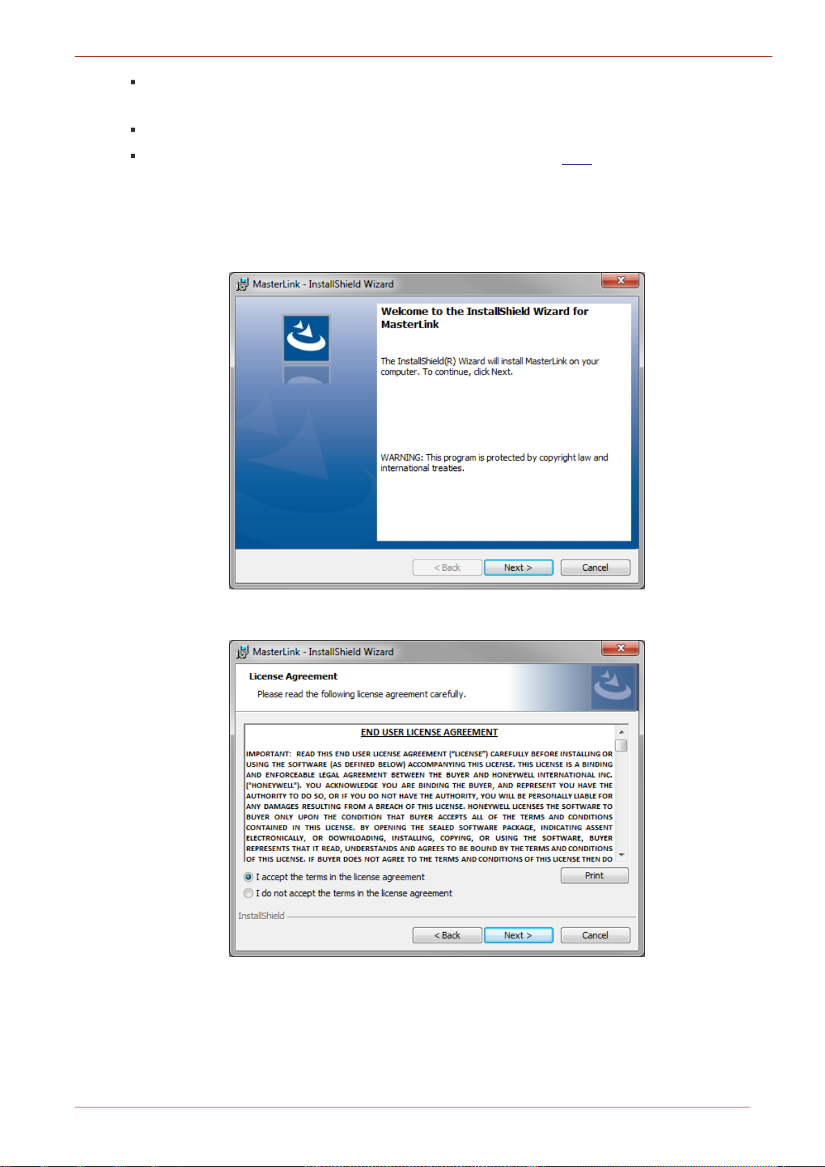
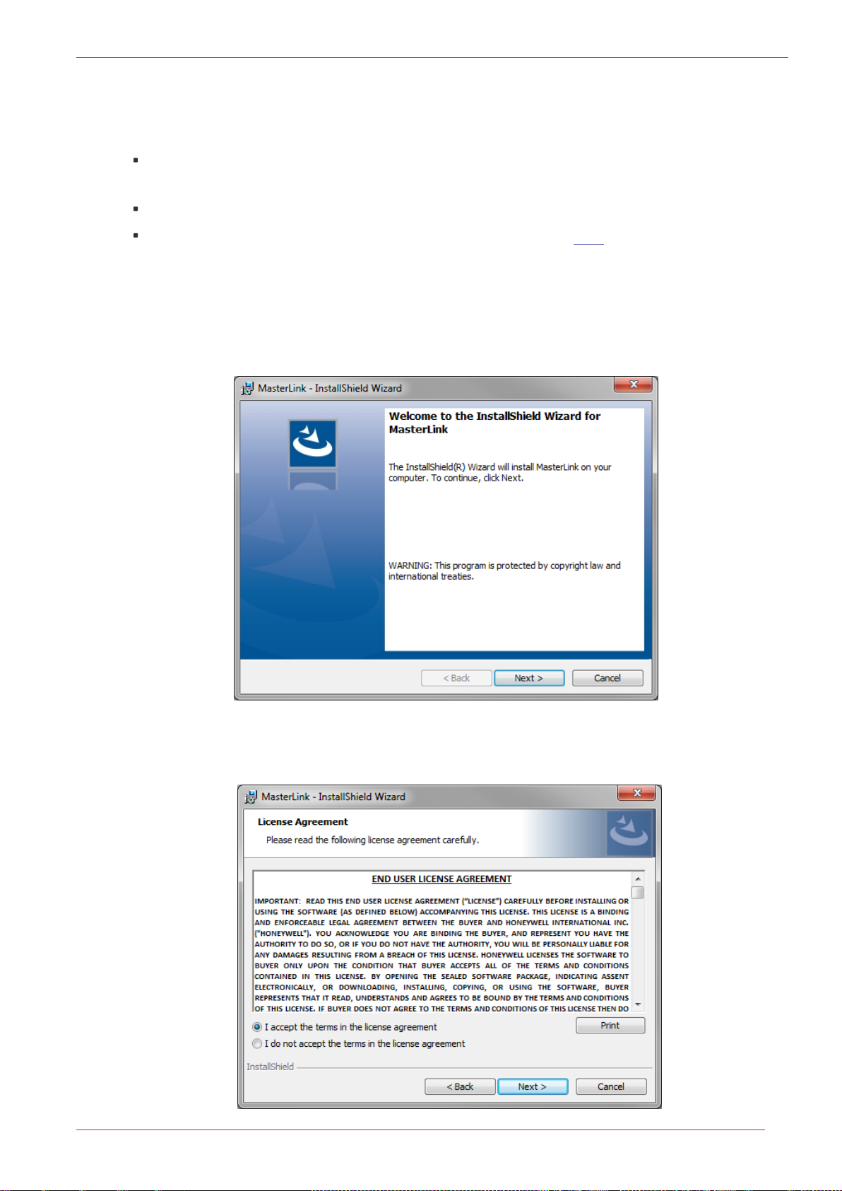
1. Launch the installer. The MasterLink - InstallShield Wizard appears. Click Next.
2 Installation
2. The License Agreement page appears. Click I accept... and then click Next.
Honeywell | 10
Page 15
2 Installation
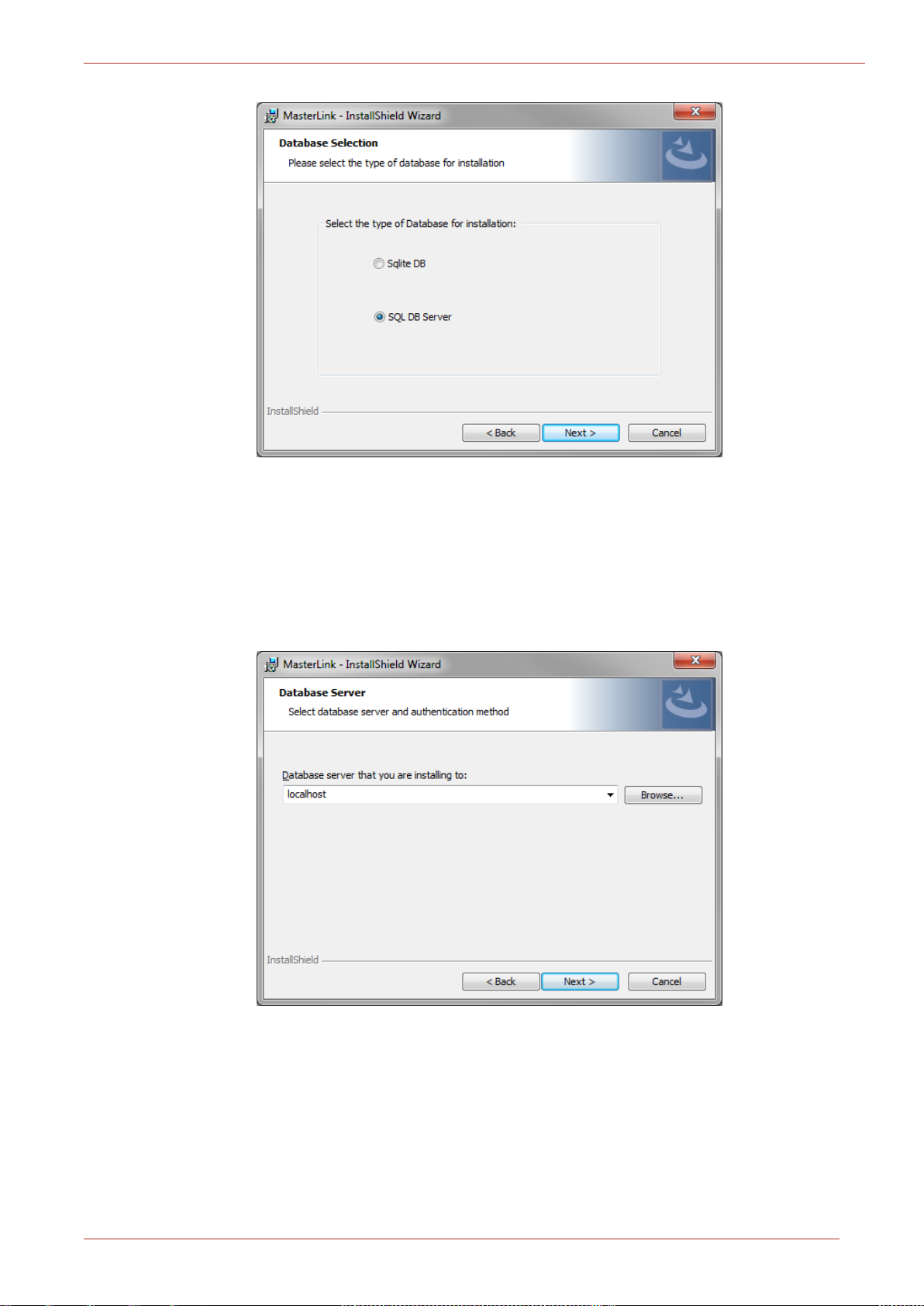
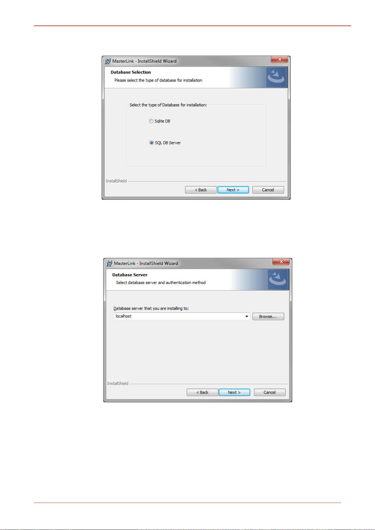
3. The Database Selection page appears. By default, SQL DB Server is selected.
If you choose to continue with a SQL DB Server for installation, then you will see the
following page (as shown in step 4), where you need to select the database server
instance.
Click Next to continue.
4. The Database Server page appears. Click Next.
Honeywell | 11
Page 16
2 Installation
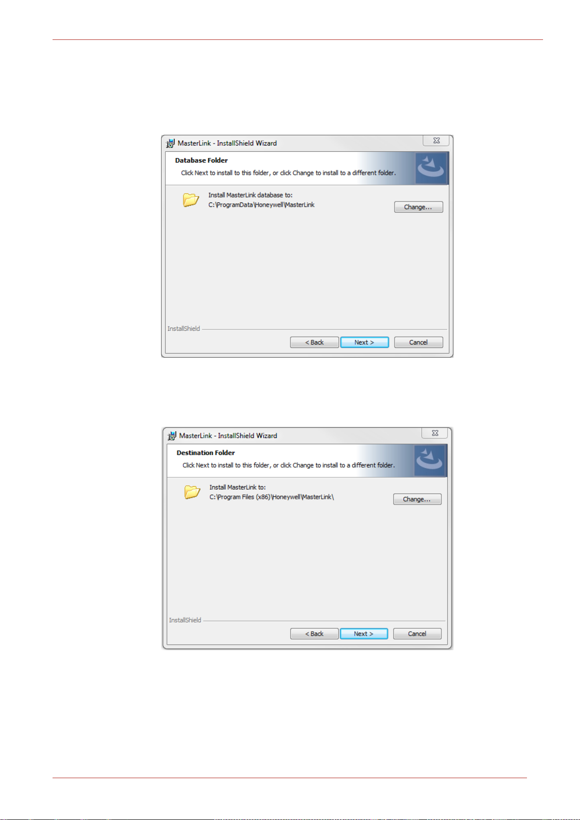
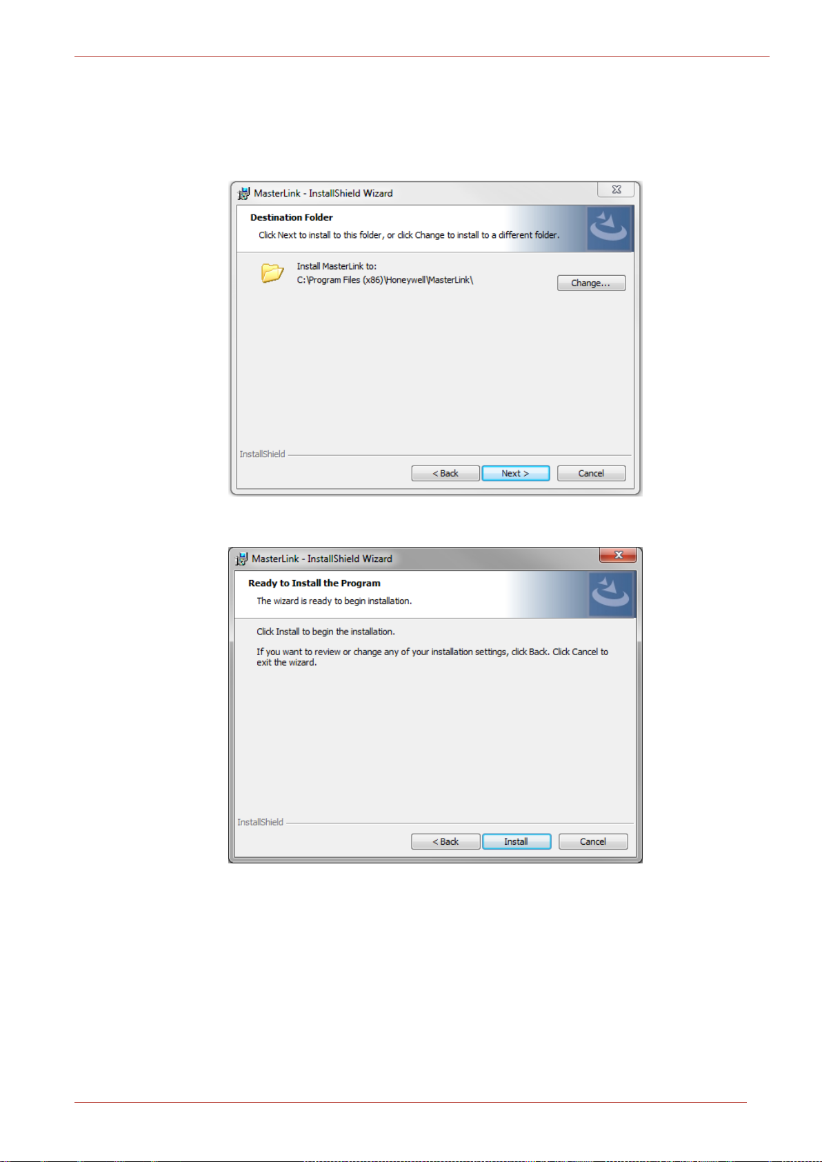
5. The Database Folder page appears. Browse and select the folder where you need to install
MasterLink and database files.
Click Next.
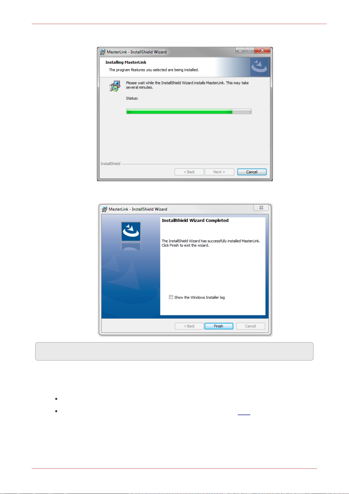
6. The Destination folder page appears, displaying information about the default destination
folder.
Click Next.
Honeywell | 12
Page 17
2 Installation
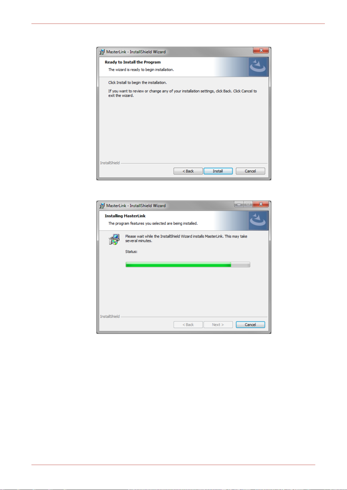
7. The Ready to install the Program page appears. Click Install to continue.
Honeywell | 13
Page 18
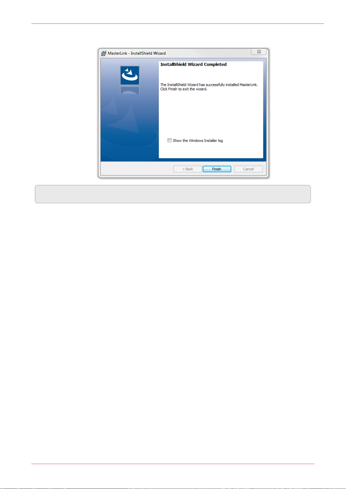
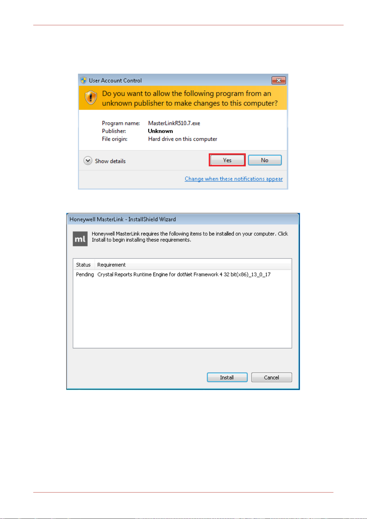
8. Finally, click Finish to complete.
2 Installation
Note: Select the check box to view the Installer log.
Honeywell | 14
Page 19
2 Installation
2.4.1 Installing MasterLink with remote SQL Server
Prerequisites:
If you are using SQL Server, then a SQL Server instance must be installed before installing
MasterLink.
Administrative Privileges are required to install the application.
Ensure Masterlink.exe and Redist folder should be in the same path to avoid any errors on
crystal report.
To Install MasterLink with remote SQL Server
1. Right-click Setup file and then click Run as administrator. The MasterLink - InstallShield Wiz-
ard appears. Click Next.
2. The License Agreement page appears.
Click I accept the terms in the license agreement and then click Next.
Honeywell | 15
Page 20
2 Installation
3. The D
atabase Selection page appears.
By default, SQL DB Server is selected. If you choose to continue with a SQL DB Server
for installation, then you will see the following page (as shown in step 4), where you
need to select the database server instance. Click Next.
4. The Database Server page appears.
Honeywell | 16
Page 21
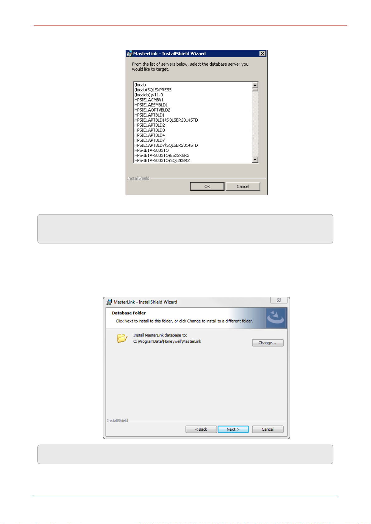
You can browse and select a database on your network. Click OK.
2 Installation
Click Next after selecting the required database.
Note: If you are using a database instance on your network, you need to have domain user per-
mission.
5. The Database Folder page appears. Click on Change and enter the path on the remote
machine where user intends to create the Database files. The path selected on remote
machine should not exist on the machine where the installer is running.
Click Next.
Note: The path selected on remote machine should exist on remote machine.
Honeywell | 18
Page 22
2 Installation
6. The Destination folder page appears, displaying information about the default destination
folder. The path selected on remote machine should not exist on current machine where
installer is running.
Click Next.
7. The Ready to install the Program page appears. Click Install to continue.
Honeywell | 19
Page 23
2 Installation
8. Click Finish to complete.
Note: Select the check box to view the Installer log.
2.5 Installing MasterLink with SQLite
Prerequisites:
Administrative Privileges are required to install the application.
Ensure Masterlink.exe and Redist folder should be in the same path to avoid any errors on
crystal report.
Honeywell | 20
Page 24
2 Installation
1. Right-click Setup file and then click Run as administrator. Allow the program to make
changes to your computer by clicking Yes.
2. Click 'Install' to allow the Crystal Reports installation on your machine.
Honeywell | 21
Page 25
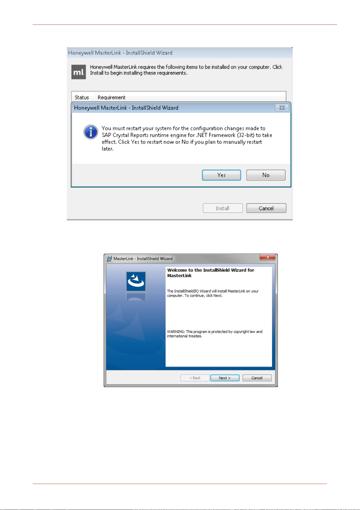
3. For smooth installation, click 'Yes' to allow the changes to be effective immediately.
2 Installation
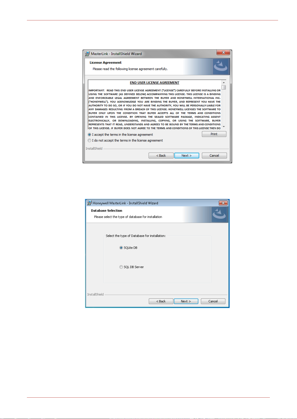
4. The MasterLink - InstallShield Wizard appears.
Click Next.
Honeywell | 22
Page 26
2 Installation
5. The License Agreement page appears.
Click I accept the terms in the license agreement and then click Next.
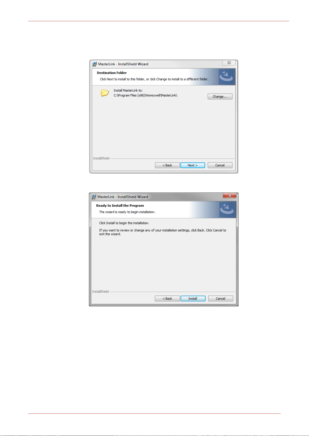
6. The Database Selection page appears. By default, SQLDB Server is selected. User is required
to select SQLite DB.
Click Next.
Honeywell | 23
Page 27
2 Installation
7. The Destination folder page appears, displaying information about the default destination
folder.
Click Next.
8. The Ready to install the Program page appears. Click Install to continue.
Honeywell | 24
Page 28
2 Installation
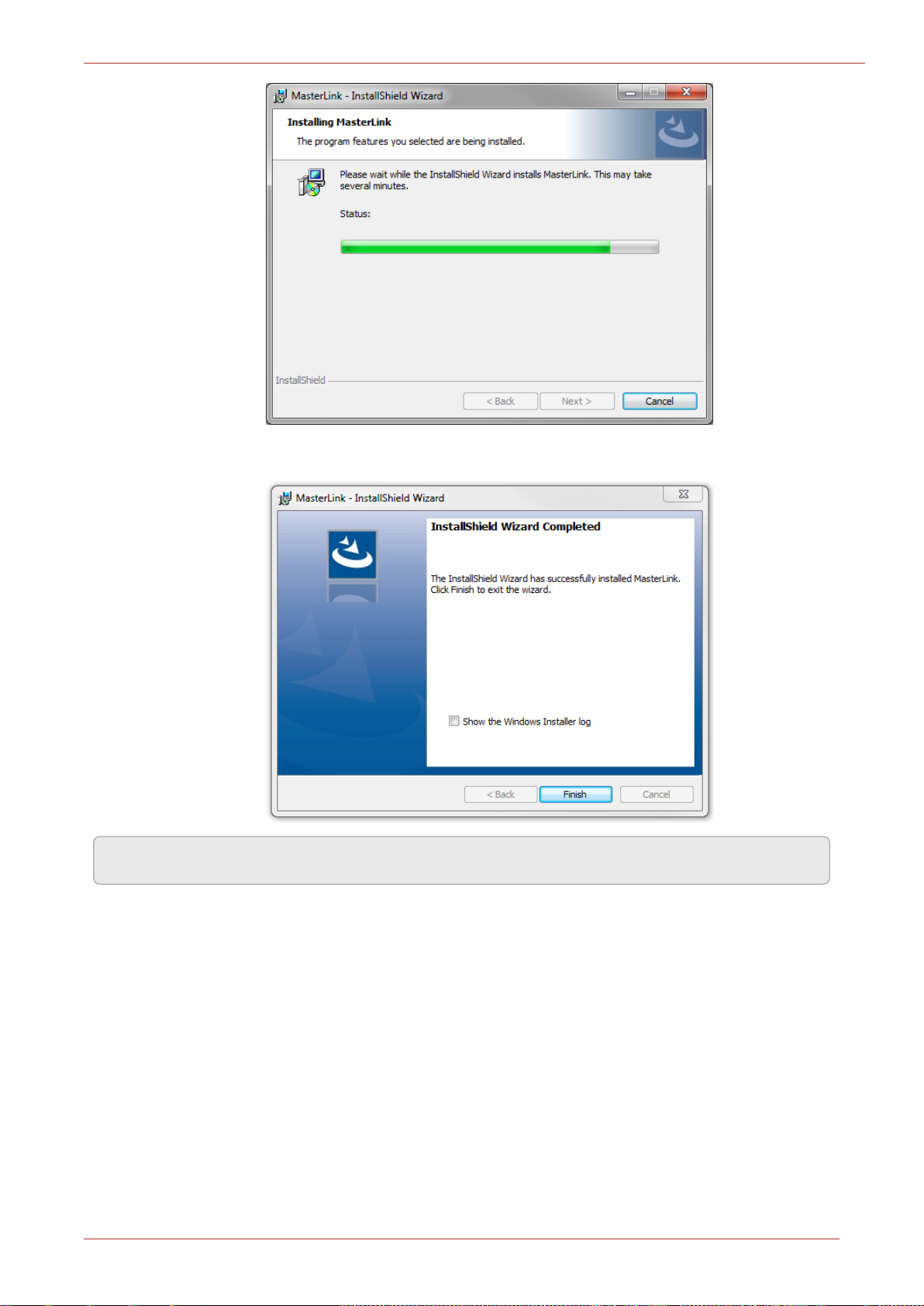
9. Click Finish to complete.
Note: Select the check box to view the Installer log.
Honeywell | 25
Page 29
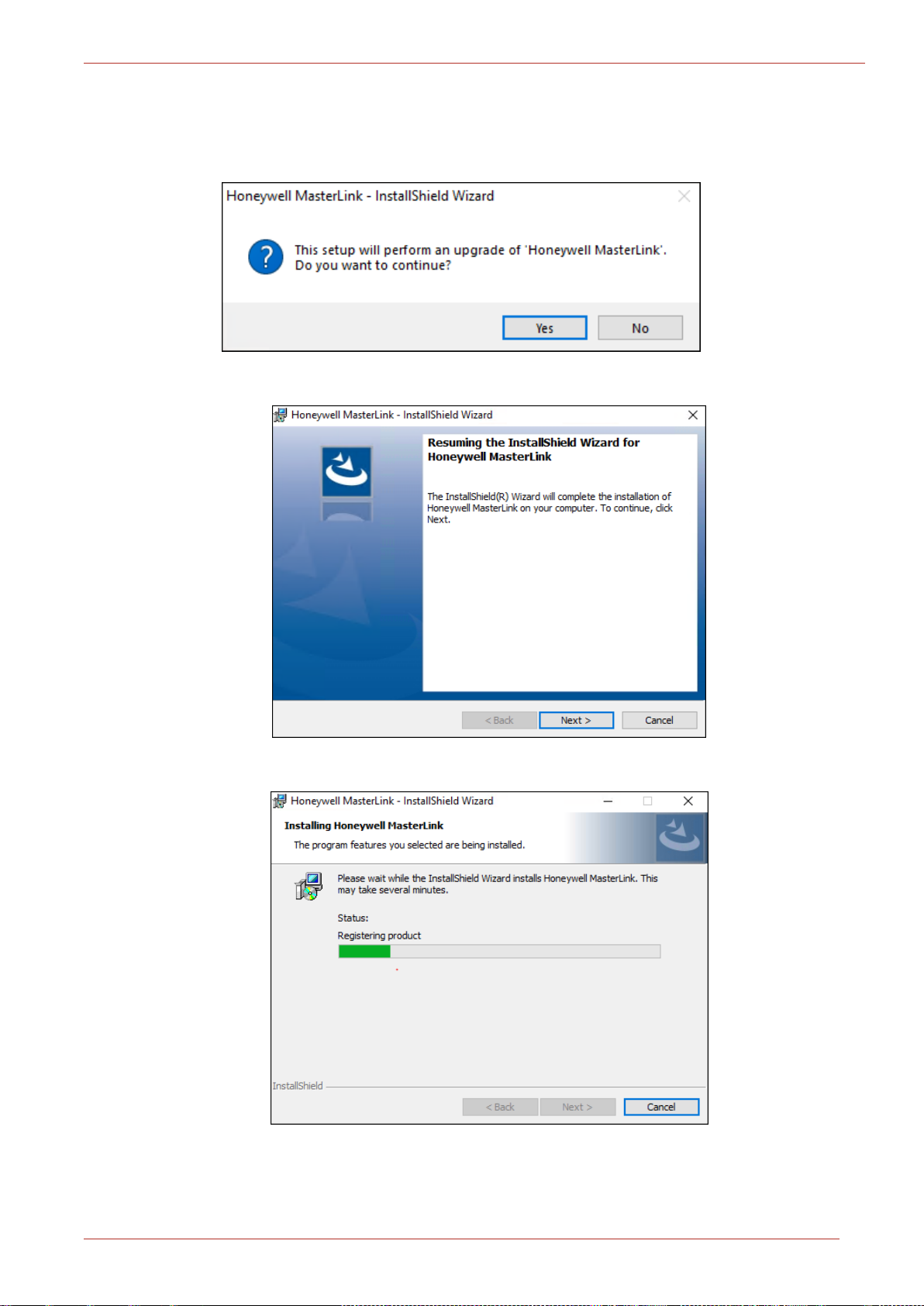
2.6 Upgrading MasterLink with SQLite/ SQL Server
1. Right-click Setup file and then click Run as administrator. Allow the wizard to perform an
upgrade to your computer by clicking Yes.
2. The MasterLink - InstallShield Wizard appears. Click Next.
2 Installation
View the download process in the progress bar.
Honeywell | 26
Page 30
2 Installation
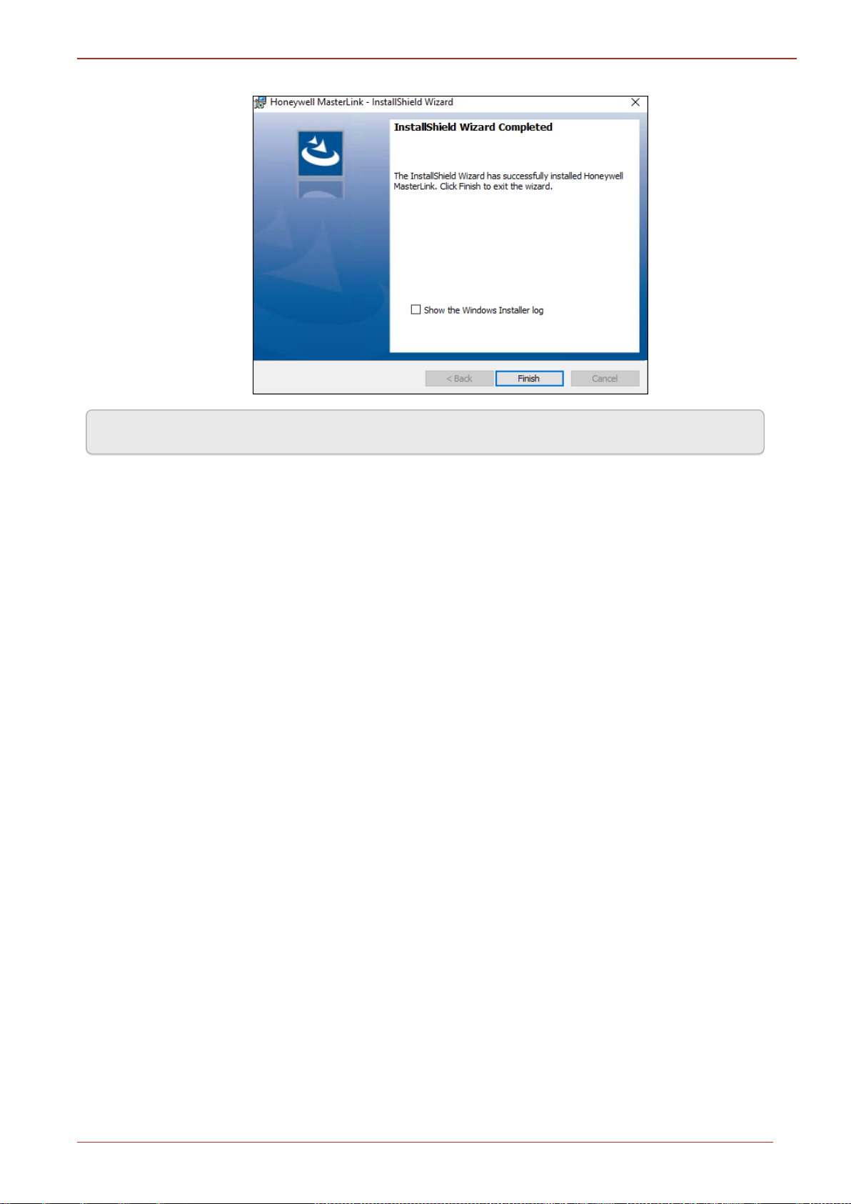
3. Click Finish to complete.
Note: Select the check box to view the Installer log.
2.7 Post Installation Steps
1. To log on to MasterLink application, users need access to C:\Pro-
gramData\Honeywell\Masterlink. By default, all users under Users group has the required
privileges.
If a user falls under any other user group, then administrator should give “Full Control” priv-
ileges on folder “C:\ProgramData\Honeywell\Masterlink” for that particular user group.
Honeywell | 27
Page 31

2 Installation
If SQL server is used as a database while installing the MasterLink application, then all users who
will use the application must be provided DBO access on SUITE32 database.
Honeywell | 28
Page 32

3 MasterLink User Interface
3 MasterLink User Interface
This chapter describes the steps of getting started with MasterLink. This chapter also explains the
user interface along with the different features that are available in separate tabs.
DISCLAIMER: Please DONOT compare or verify the software build number shown in this
manual with the build that you are using. Special demonstration builds were used specifically to
capture screenshots for this manual, and so the build number may differ from the version that
you are using.
3.1 Getting Started
On launching the MasterLink, you will see a screen to log on.
3.1.1 User Creation and Activation Process
To start using MasterLink Application, one must create a Site Administrator user who
can in turn create multiple users with different privileges based on the business require-
ments.
3.1.1.1 Site Administrator Creation
The Site Administrator must initially get a MasterLink license from Honeywell Process
Solutions. This license key can be used to register a Site Administrator in the Master-
Link Application. Contact TAC team to get your license key.
Honeywell | 29
Page 33

3 MasterLink User Interface
3.1.1.2 Creating Users
After the site administrator is registered, they can create new users using Security fea-
ture. To know more on passkey generation refer to User Configuration.
For individual user, the generated license key must be emailed to the respective users
allowing them to register and start using MasterLink application.
3.1.1.3 User Registration
For a first time user, click New User and register. User is required to register with
license key provided by the site Administrators. The User name you enter while regis-
tering must match with the user name used while creating the license key.
Enter the log-in details, browse and select the license key, and then click Register.
The Login screen appears.
Log on with your credentials. Click Sign In.
Honeywell | 30
Page 34

3 MasterLink User Interface
The following screen is displayed:
Refer MasterLink Installation Guide for understanding the prerequisites and installation instruc-
tions.
MLK files (license key) generated with MasterLink Old Release (R510.1, R510.2, R510.4 till Build
11.1.39) will not work with Release R510.4 Build 11.1.41 onwards.
The following error appears if you are using the old license key.
Honeywell | 31
Page 35

3 MasterLink User Interface
3.1.1.4 Forgot Password
If users forget their password they can reach out to the site Administrator for a new passkey. Once
the key is received, users can reset their passwords by clicking the Forgot Password link. The For-
got Password screen appears.
Enter your user-name, browse and select the license key, and finally enter your new password. Click
Reset to log-in with the new password.
Honeywell | 32
Page 36

3 MasterLink User Interface
3.2 Sites
The 'Sites' screen lists all sites configured in the MasterLink application. A Site refers to a field
instrument such as:
1. Accutest
2. CloudLink Modem
3. CNI4
4. EC 350
5. EC 350 + CloudLink Modem
6. ECAT
7. ER
8. ERX
9. ERX 350
The user can also add a new Site, as well as edit or remove an existing Site. From the 'Sites' screen,
users can connect to a device deployed on the field.
This section describes the steps to configure and add a site to MasterLink. It also explains how to
connect and communicate with existing sites.
Note: In Coexistence scenario, any CloudLink related sites that are added using New Master link
will be displayed as “Unknown” sites in MasterLink.
10. ERX 350 + CloudLink Modem
11. Mini
12. Mini-AT
13. Mini-Max
14. PT Modbus
15. Pulse Accumulator
16. TCI
17. Turbo Corrector
18. Turbo Monitor
Note: By Default, EC 350 will be selected in Instrument Type drop-down.
Honeywell | 33
Page 37

3.2.1 Add Site
Serial IrDA Modem Internet*
Accutest
ü û ü ü
CloudLink
ü û û ü
CNI4
ü û û ü
EC 350
ü ü ü ü
EC 350 + CloudLink
ü ü û ü
ECAT
ü û ü ü
ER
ü û ü ü
ERX
ü û ü ü
ERX 350
ü û ü ü
ERX 350 + CloudLink
ü ü û ü
Mini
ü û ü ü
Mini-AT
ü û ü ü
Mini-Max
ü û ü ü
PT Modbus
ü û ü û
Pulse Accumulator
ü û ü ü
TCI
û ü û û
In the 'Site Management' screen, you can configure and connect to site.
3 MasterLink User Interface
Site can be connected and configured over the following interfaces based on deployment (device
type):
Honeywell | 34
Page 38

3 MasterLink User Interface
Serial IrDA Modem Internet*
Turbo Corrector
ü û ü ü
Turbo Monitor
ü û ü ü
* Assuming that a cellular modem is being used.
Note: Before adding a new site, ensure that you have configured your communication settings
under Settings > Communications Setup.
Click the '+' icon on the top-right corner of the screen to create a new site or a field device. This
function is used to add site information to the Site List.
Configure the site details and click Save.
Attention: In integrated mode, Site IDs must be identical for device and modem. (If you are using
EVC or Recorder's Site ID with 8 digits, then Modem ID should be Last 6 digits).
Also, an integrated site must be added in 'Integrated' mode only. Otherwise only the CloudLink
modem will be added as a site followed by a sync with the central server. A Site once created
and synced with the central server cannot be deleted from the server. However, the site can be
deleted from Technician's mobile app.
Attention: Site IDs must not be changed after it is synced with the central server. If the Site ID is
changed after the sync, then the mobile iOS app may not work as expected.
While adding an integrated site, the EVC or Recorder's site IDs will be shown as Site IDs of integ-
rated sites. The CloudLink modem's Site ID will not be displayed as the Site ID of the integrated
Honeywell | 35
Page 39

3 MasterLink User Interface
site. However, the Site ID of the CloudLink modem will still be used to scan and detect the integ-
rated site.
The 'Site Management' screen has 2 views:
1. Tile View:
2. List View:
Honeywell | 36
Page 40

3 MasterLink User Interface
3.2.2 Connecting to a Site
When you log on to MasterLink and if you are NOT connected to a site or a device, you will see the
following screen.
Click on the Site tab or the Connect to a site link to get started.
Configured sites can be connected using the Site/Site Management screen of MasterLink.
Note: To connect an instrument through serial interface or modem configure the communication
settings in the Settings tab.
After successfully connecting to the device, the dashboard starts downloading the data.
Note: It is recommended that the user waits till the dashboard data is loaded.
EC 350 Dashboard:
Honeywell | 37
Page 41

3 MasterLink User Interface
ERX 350 Dashboard:
Note: Panels with red icons indicate that user attention is required.
Honeywell | 38
Page 42

3 MasterLink User Interface
3.2.3 Direct Connect
The 'Direct Connect' feature lets the MasterLink connect to a site which is physically connected to a
computer. The Direct Connect functionality works based on the serial port or IrDA settings con-
figured under Settings > Communications Setup.
To connect a device:
1. Physically connect the instrument using a serial or IrDA interface.
2. Configure the required communication settings, go to Settings > Communications Setup.
3. Configure the user specific User ID and Access Code, go to Settings > Device Properties
4. Click Connect located at the bottom left. The device will be connected and the dashboard
starts loading.
In case of integrated device, for example CNI4 (Pulse Accumulator + CloudLink Modem). If Master-
Link is able to connect to Pulse Accumulator only and not the CloudLink Modem, then the dash-
board loads only the with the Pulse Accumulator data and notifies users that it could not connect
to CNI4. This scenario arises if the site is already added as CNI4, but only the Pulse Accumulator is
connected. In this case, If the site is not already added, MasterLink will just treat the connected
device as standalone Pulse Accumulator.
Honeywell | 39
Page 43

3 MasterLink User Interface
3.3 Dashboard
On successful site connection, dashboard data gets loaded automatically based on the 'Auto Down-
load Settings'.
Dashboard has various panels that show current data from the connected site. User can further
drill down to see relevant data by clicking on respective panels. The dashboard automatically reads
and displays the following data:
Critical instrument data
Active alarms
Configuration checks based on the item template file
Time Sync
Firmware
Audit Trail data
Instrument/Modem Power
Using Data Download Settings, you can configure the dashboard data and as per your requirement.
Note: The instrument data can vary based on the connected device type.
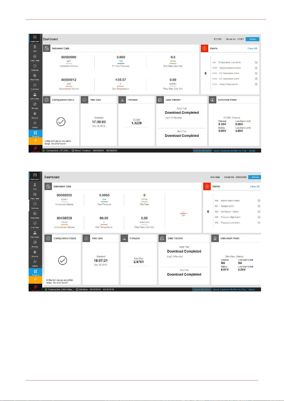
EC 350 + CloudLink Modem Dashboard:
Honeywell | 40
Page 44
3 MasterLink User Interface
EC 350 Dashboard:
Mini-Max Dashboard:
Honeywell | 41
Page 45

3 MasterLink User Interface
ERX 350 + CloudLink Modem Dashboard when the device is externally powered:
ERX 350 + CloudLink Modem Dashboard when the device is battery powered:
Honeywell | 42
Page 46

3 MasterLink User Interface
Icons The icons displayed on the footer are used to illustrate the following:
3.3.1 User Interface
User Interface consists of the following sections:
Note: You can now connect to an Instrument and Modem with dedicated settings via Instrument
and CloudLink buttons on the left pane of the dashboard.
- You can connect to CloudLink Modem directly by setting the necessary configurations
in Settings -> Communications Setup option.
- You can connect to an Instrument i.e., EC 350. ERX 350, Mini-AT, Integrated (EC
350+CL) etc.. directly by setting the necessary configurations in Settings -> Communications Setup
option.
Tiles related to the application features include:
Header contains:
MasterLink application release and build number
About MasterLink button
MasterLink Application help button
User account button
Footer contains the following information:
Honeywell | 43
Page 47

3 MasterLink User Interface
- Not connected to any site, - Connecting to a site, - Connected
to a site
Comm Monitor
Displays all the communications (command/responses) between MasterLink application and the connected site.
Send Capture
Buffer to File
Allows the user to save all the communication into a file for analysis.
Email
This is ONLY available in online mode or connected mode. Allows you to
email a set of files to the TACsupport team MI-TAC-Sup-
port@Honeywell.com.
After an active connection is established and once the dashboard is downloaded click on Email
option, a pop-up window appears as below:
Note: This Email option is an Outlook functionality. User should be outlook configured before
proceeding with this option.
Click 'Yes' if you wish to proceed else 'No'. Once you proceed further, you will be redirected to
Microsoft Outlook message window. This email will be sent to TAC Support team with minimal
sender details which is a mandatory fill before sending to the TAC Support.
Honeywell | 44
Page 48

3 MasterLink User Interface
1. Email is auto directed to TAC support email communication address.
2. Set of files (Item, alarm, event, diagnostic and audit logs) zipped to be sent as an attach-
ment.
3. Mandatory minimal contact details to be filled by the sender before sending the Email.
When outlook is not pre-configured in your machine, the below pop-up screen appears.
You can save all the file attachments in the pre-defined folder path : C:\Pro-
gramData\Honeywell\Masterlink\Email. As the outlook is not configured, you can only save the
documents but, not send them.
Honeywell | 45
Page 49

3 MasterLink User Interface
When you click the ShortList button, MasterLink will automatically connect to the site and opens
the Shortlist tab. Also, a ReadData File window opens, where you can select the Shortlist file based
on which a Shortlist report is generated.
After opening the shortlist file, the following screen appears.
Honeywell | 46
Page 50

3 MasterLink User Interface
3.3.2 Instrument Data
The Dashboard shows current instrument data from the connected site. This data is read from the
instrument and displayed under the Instrument Data widget.
On clicking any value, further details are displayed.
Honeywell | 47
Page 51

3 MasterLink User Interface
3.3.3 Alarms
User can drill down to alarm and event history by clicking on the number of active alarms dis-
played on the dashboard.
Individual alarms can be cleared by clicking
All active alarms can be cleared at once, by clicking Clear All
User can access alarm log and event log reports from the Dashboard.
Honeywell | 48
Page 52

3 MasterLink User Interface
Refer Auto Download Settings page for more details.
Honeywell | 49
Page 53

3 MasterLink User Interface
3.3.4 Configuration Check
After connecting to the instrument, MasterLink compares values of items defined in the template
with actual values in the instrument and reports the status of Configuration Check widget on Dash-
board. User can correct the values from the drill-down screen.
When all the values are corrected, the Configuration Check widget reports status as All items found
are within range. No error found!
When the customized files are a part of default templates list the Dashboard will show Multiple
item templates exist in the Configuration Check panel. See below.
Honeywell | 50
Page 54

3 MasterLink User Interface
User can drill-down the panel screen to view the list of templates available. You can select any tem-
plate for config check from the drop-down and correct the values if required.
Refer Item Template Configuration page for more details.
Honeywell | 51
Page 55

3 MasterLink User Interface
3.3.5 Time Sync
'Time Sync' page provides a user configurable option to enable/disable auto time synchronization
of the connected device with your PC.
Alternatively, time can be synchronized manually by clicking onSync.
Time difference trigger point is taken into account when application reports time synchronization
status.
Note: In case of integrated devices, Time Sync for both device and modem are considered but
user can see only Device’s date and time in the Dashboard Time Sync panel. If device time is in
sync but the modem time is not, the Time Sync panel shows an error.
Note: The Computer time displayed on the Time Sync is not dynamic. It is the actual PC time
when the Time Sync tab is opened. It changes only when the Time Sync tab is refreshed. The
Computer time can be different from the actual PC time.
Refer Time Sync Properties page for more details.
Honeywell | 52
Page 56

3 MasterLink User Interface
3.3.6 Firmware Update
Dashboard reports the current firmware revision/version(s) loaded in the instrument(s).
Firmware versions can be upgraded using the firmware drill down screen.
Honeywell | 53
Page 57

3 MasterLink User Interface
The Update screen consists of three tabs:
EC 350 Firmware Upgrade
CloudLink Modem and
Certificate
The current firmware version details are displayed on the relevant update screen. The firmware file
to be used can be browsed and version of the firmware to be upgraded is displayed under 'Selected
Firmware Details' section.
Browse and select the required firmware file to be uploaded and observe application displays the
information of firmware file selected under 'Selected Firmware Details' section.
The new firmware is transferred to the instrument and then installed.
Note: MasterLink R500 Application (Windows & Mobile) supports firmware upgrade to the EC
350 and CloudLink Modem, only if the devices have the following firmware versions:
CloudLink Modem: 1.0001
EC 350: 1.1032
It is not recommended to perform a firmware upgrade, unless the devices are running on the ver-
sions mentioned above.
Honeywell | 54
Page 58

3 MasterLink User Interface
3.3.7 Data Transfer
As soon as you connect an instrument to MasterLink Software Applications, Audit Trail data and
Item File from the instrument is automatically downloaded.
Screen shot showing Audit Trail data.
Instrument data is automatically downloaded if the Auto Download settings are enabled.
Honeywell | 55
Page 59

3 MasterLink User Interface
Refer Auto Download Settings for more details.
Honeywell | 56
Page 60

3 MasterLink User Interface
3.3.8 Instrument or Modem Power
While connecting to the site, application reads the type of power source (Battery or External). Cor-
responding voltage is displayed on Dashboard.
A drill down on the panel depicts a plot of battery/external voltage against time.
Note: Instrument/Modem Power drill down can be done on 1.4030 firmware version & 15.1.25.0
MasterLink build version onwards only.
Scenario 1: Below is the Standalone EC 350 battery voltage plot.
Scenario 2: Below is the Standalone CloudLink battery voltage plot.
Honeywell | 57
Page 61

3 MasterLink User Interface
Scenario 3: B
powered.
elow is the Integrated (EC 350 + CL) battery voltage plot when EC 350 is battery
Scenario 4: Below is the Integrated (EC 350 + CL) battery voltage plot when CloudLink is battery
powered.
Honeywell | 58
Page 62
Honeywell | 59
3 MasterLink User Interface
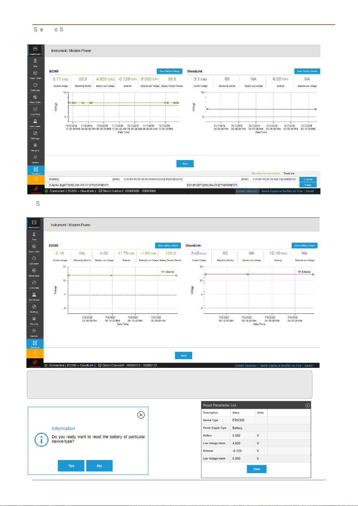
S
c nari : Below is the Integrated (EC 350 + CL) battery voltage plot when both EC 350 and
CloudLink is battery powered.
Scenario 6: Below is the Integrated (EC 350 + CL) external supply voltage plot when both EC 350
and CloudLink is externally powered.
Note: In case of new battery replacement, click on 'New Battery Reset' to read the list of para-
meters in the device. See below.
[
Page 63

3 MasterLink User Interface
3.3.9 Update User Account
If privileges associated with user role are modified, then the respective user account needs to be
updated with a new passkey shared by administrator.
Click on username on the dashboard header and select Update User Account.
The Update User Account pop-up appears.
Update user account using the new key sent by the administrator.
Honeywell | 61
Page 64

3 MasterLink User Interface
3.3.10 Change Password
Password of an existing user can be changed using the Change Password option.
Click on user-name and select Change Password.
The Change Password pop-up appears.
Type current password, and then the new password. You also need to confirm your new password
by typing it again.
After you finish making the required changes, click Change to save the changes.
Honeywell | 62
Page 65

3 MasterLink User Interface
3.4 View and Edit
This tab has the functionality for performing various interactions with device such as read/write
item, read item file etc.
3.4.1 Configure by Group
MasterLink must be connected to an instrument for this function to work. Configure by Group tab
displays groups categorized by items corresponding to connected instrument.
Instrument items (which vary per type of instrument) can be grouped by function. The Configure by
Group tab displays the item values that apply to the type of connected instrument after grouping
them by function. For example, all items related to pressure calibration are displayed on one
screen.
When connected to an instrument, you can click on the Read button to read item values from the
connected instrument.
To change item values:
1. Click on the desired function group (panel on left) to see the group items (panel on right).
2. Select an item by clicking the check box next to it.
3. Enter a value for the selected item number, and click on Write Item button.
Note: Third Pressure P3 is supported ONLY for MIWI350 with Pressure expansion board from
1.4016 firmware version onwards. Instruments (EC 350, ERX 350) prior to firmware version
Honeywell | 63
Page 66

1.3318 will not support P3.
3 MasterLink User Interface
Advanced Options: It has three options
1. Raw Item Access - You can modify (Read/Write) the value of any item by typing an item num-
ber in the pop-up below.
2. Read Raw Item File - Reads all the item numbers in one click.
3. Shut Down - Clicking this will shut down the device.
Honeywell | 64
Page 67

3 MasterLink User Interface
Honeywell | 65
Page 68

3 MasterLink User Interface
3.4.2 Configure by Item
MasterLink must be connected to an instrument for this function to work as different instruments
have different items and groups categorized. Configure by Item tab displays all items cor-
responding to connected instrument and by default, all items are sorted by item number.
An item can be searched with Item number or description. The check box must be checked in order
to read/write value(s) of any item.
To change item values:
1. Select an item by clicking on the check box next to it.
2. Enter a value for the item number.
3. Click Write Item after making the changes. This will write the new item value to the connected
instrument.
Sliding the mouse over the column divider until a cross is displayed, then dragging it to the desired
width can re size the column widths. Use the up/down arrows or across arrows for full viewing of
all data fields.
Honeywell | 66
Page 69

3 MasterLink User Interface
Click on Advance Options and select Raw Item Access to modify the value of an item.
Search for a particular item either by number or description.
Read Raw Item File will read all the item numbers in one click.
Clicking on Shut down will shut down the device.
Note: When Pressure factor mode (Item 109) is changed from Fixed to Live, P1 Transducer
Enable (Item 1052) should be manually changed from NO to YES to get the Live value of P1
Gas Pressure (Item 008).
Honeywell | 67
Page 70

3 MasterLink User Interface
Note: When Temperature factor mode (Item 111) is changed from Fixed to Live, T1 Temp Probe
Enable (Item 1055) should be manually changed from NO to YES to get the Gas Temperature
(Item 026).
Note: When Supercompress Method (Item 147) is changed to Fixed Super, Unsquared Super-
compress (Item 047) and Squared Supercompress (Item 116) will be updated with Fixed Unsq
Super Factor (Item 1457) within 30 seconds.
Honeywell | 68
Page 71

3 MasterLink User Interface
3.4.3 Send Item File
An Item File stores the current instrument’s item code values on your computer in a file. You can
configure different items corresponding to an instrument in an Item File and then send it to the
device.
Click Browse and select the item file. (.IE3 for EC 350, .ICL for CloudLink Modem, .ECL for EC 350 +
CloudLink Modem)
View the values configured for different item numbers.
Honeywell | 69
Page 72

3 MasterLink User Interface
Device Type Supported Types in Send Item File
Accutest Pressure1, Pressure2, Temperature, Non-Cal Items
CloudLink Modem Non-Cal Items
CNI4 Non-Cal Items
EC 350 Pressure1, Pressure2, Temperature, Non-Cal Items
EC 350 + CloudLink Pressure1, Pressure2, Temperature, Non-Cal Items
ECAT Pressure1, Temperature, Non-Cal Items
ER Pressure1, Pressure2, Temperature, Non-Cal Items
ERX
Pressure1, Pressure2, Pressure3, Board Temperature, Non-Cal
Items
ERX 350 Pressure1, Pressure2, Temperature, Non-Cal Items
ERX 350 + CloudLink
Modem
Pressure1, Pressure2, Temperature, Non-Cal Items
Mini Pressure1, Temperature, Non-Cal Items
Mini-AT Pressure1, Pressure2, Temperature, Non-Cal Items
Mini-Max Pressure, Temperature, Board, Non-Cal Items
PT ModBus Non-Cal Items
Pulse Accumulator Non-Cal Items
TCI Temperature, Non-Cal Items
Turbo Corrector Pressure1, Pressure2, Temperature, Non-Cal Items
Turbo Monitor Non-Cal Items
View the values configured for different item numbers. The Item types will differ based on the con-
nected instrument.
Refer to the table below for the item types displayed for specific devices.
Click Send to Device to send the Item File to the connected field instrument.
Honeywell | 70
Page 73

3 MasterLink User Interface
3.4.4 Logging Configuration
Available only for EC 350 and ERX 350 devices
Using MasterLink software, an instrument can be configured to contain as many as 5 independent
logs, each with its own collection of item values and collection (sample) frequency. Each log can be
configured to collect values for up to 20 items.
You cannot add/enable P3 items to the log configuration if the Pressure Expansion Board is not
physically connected to the device (EC350/ERX350) hardware. And if you still try to configure, a
pop-up error window appears as seen below.
Honeywell | 71
Page 74

3 MasterLink User Interface
The order of the items in the Log Configuration list determines the order in which the values are
stored and thus the order in which they will later appear in a report. Items in the list can be moved
up and down to change the order.
The selected items from a log can be removed by clicking
The configuration can be saved for future references to a configuration file (*.cnfg) with the Save
setup to file button. It can later be retrieved with the Read setup from file button. Only *.cnfg files
can be read; item files (*.ie3) are not compatible.
Honeywell | 72
Page 75

3 MasterLink User Interface
In the Allocate log memory tab, configure the percentage of available memory which can be alloc-
ated to each log.
Note: The sum total of memory allocated for all logs must be equal to 100%.
The consequence of a particular allocation setting is reflected in the number of days' worth of data
as well as the number of records that can be written before overwriting will occur. The smaller a
log’s allocation, the less data it will be able to store. When the limit is reached, the oldest records
will be overwritten with the newer ones.
Note: A log’s interval setting will impact days, but not record numbers.
The Enable check-boxes may be used to suspend data collection for one or more logs. A log’s exist-
ing records will not be affected when the log is disabled.
Ensure that the device is connected to MasterLink. Click Send to Instrument to push the log con-
figuration to the device. A few seconds will be required for the transfer. A window should appear
indicating Successfully Configured.
Click Read setup from Device to read logging configuration settings from the connected instru-
ment.
Attention: When you change the log configuration by modifying the memory allocation, all exist-
ing logs will be erased.
Attention: It is recommended to save the item file and log configuration file before changing the
memory allocation of the logs.
Honeywell | 73
Page 76

3 MasterLink User Interface
3.4.5 Manage User Table
Access to an instrument can be controlled by defining users and assigning them Pass codes with
defined privileges. Start by creating a role, then assign the role to the user and define Passcode.
User IDs and Pass codes are used to log-in to an instrument. When creating a user account, assign
User ID, and a Passcode, and assign a role to the new user. Valid User IDs are 0 through 99
(decimal numeric). Valid pass codes are 00000 through 99999 (decimal numeric). The Passcode
must be 5 digits in length.
Click on Open and load an existing saved .UTE (Manage User Table) file.
Based on the privileges assigned to the role, the value of the privilege changes or vice-
versa.
1. Click the check box under privileges to assign permissions to the role.
2. After a role is created, click Add User to create a new user.
3. After updating the privileges, click Update to save the changes.
Honeywell | 74
Page 77

3 MasterLink User Interface
The following privileges can be granted:
Modify Open Items
Modify Event Items
Modify Sealed Items
Can Read Event Log
Can Change User table
HMI Level 2 Access
HMI Level 3 Access
CloudLink Write
To add a user:
1. Click Add User to add new users.
2. Enter the User ID and Password.
3. Assign a role or change the role of an existing user by selecting a different role from the Role
drop-down.
4. Click Add to complete the process of adding a new user.
Click Save As to save a copy of the user table created. This user table is encrypted and saved in
.UTE format.
Click on Send to Device to send a user table to the connected instrument.
Note: For CNI4 device, the User Table must be created with only one user.
Honeywell | 75
Page 78

3 MasterLink User Interface
3.4.6 Manage Shortlist
A Shortlist is the same as the standard Item list (stores the current instrument’s item values),
except that you can customize it to include required items.
To create a Shortlist:
1. Start by selecting the instrument type.
2. The items displayed in the Items column are populated based on the selected instrument
type.
3. Use the Add button to move selections to the Selected Items pane.
4. Items listed in the Selected Items column will be printed using Shortlist Report.
The Save option, saves the Shortlist to the database.
The Save Setup to file option exports the shortlist.
Note: By default, instrument specific short lists are created (all sites). Use the Site ID 1 and Site
ID2 drop-downs to create site specific short lists. The short list files are named as <SiteID1>_
<SiteID2>_yymmddhhmmss.CE3 file. Example: 44571111_44571111_161214120204
You can save and download the Shortlist as a file for later use. You can also read an existing Short-
list file.
Note: By default all shortlist files are stored in C:\Pro-
gramData\Honeywell\MasterLink\ShortListFiles.
Honeywell | 76
Page 79

3 MasterLink User Interface
3.4.7 Manage AGA-8
AGA-8 calculations determine the compressibility of natural gas and other hydrocarbons based on
it's components. These calculations are ideally designed to determine the compressibility of natural
gas. These calculations can be gross or detailed. These (.aga) files can be generated using
SuiteSQL (MasterLink SQL) software. You can use the Manage AGA-8 tab to send .aga files to a
connected instrument. This feature is supported by the following legacy Mercury devices:
Mini-Max
Mini-AT
Accutest
Turbo Corrector
ECAT
On the Manage AGA screen, Browse and then select a .aga file.
Finally click Send to send the .aga file to the connected legacy Mercury instrument.
Honeywell | 77
Page 80

3 MasterLink User Interface
3.5 Calibrate
3.5.1 Pressure Calibration P1
This procedure is used to calibrate the pressure transducer to a pressure calibration standard.
Understanding Pressure Calibration:
This is a simple two-point calibration. First, calibrate pressure at a low scale pressure and then
again at a high scale pressure. Each time, adjust the pressure calculated by the instrument to
match the reading from your pressure standard (reference standard calibrator). Adjusting the low
scale pressure is called "Zero Calibration" while adjusting the high scale pressure is called "Span
Calibration". Span calibration actually uses some of the information determined from performing
the zero calibration. For this reason, you will need to at least "sample" a low scale pressure before
you can begin the span calibration. Sampling occurs when you indicate that the pressure is ready
to be averaged.
Before starting the Pressure Calibration:
Make certain that the following items have been verified for correctness:
Pressure Calibrator
Pressure Unit Code (unit of measure)
Transducer Serial Number (assigned at the factory)
Type of Transducer (gauge or absolute)
P1 Calibration table displays current Calibration pressure and two previous pressure values along
with Calibration date in mm-dd-yy format. Current span Calibration pressure and two previous pres-
sure values are also displayed.
Honeywell | 78
Page 81

3 MasterLink User Interface
To calibrate pressure:
1. Apply a zero reference pressure (low range) to the P1 pressure transducer of the instrument,
and wait for the instrument to stabilize.
2. Click Average Now to apply a zero reference pressure to the instrument.
Honeywell | 79
Page 82

3 MasterLink User Interface
3. The averaged pressure appears. Click Change to enter a zero cal point.
Honeywell | 80
Page 83

3 MasterLink User Interface
4. Change the value to accurately match the zero reference pressure applied to the pressure
transducer. Click Apply.
Honeywell | 81
Page 84

3 MasterLink User Interface
5. Click Span Calibration. Apply a high pressure such that the pressure applied is at least 50%
more than the zero reference pressure. Wait for the pressure reading displayed on the Pres-
sure 1 dialog box to exceed the zero reference pressure by 50%.
Note: For example, if the zero reference pressure on a 100 PSI transducer equals 0.00 PSI, then
the span reference pressure must be between 50.00 and 100.00 PSI. If the zero reference pres-
sure on a 600 PSI transducer equals 0.00 PSI, then the span reference pressure must be between
300.00 and 600.00 PSI.
Honeywell | 82
Page 85

3 MasterLink User Interface
6. After the pressure stabilizes, click Average Now. MasterLink averages the reading and dis-
plays the average pressure.
7. Click Apply.
Honeywell | 83
Page 86

3 MasterLink User Interface
Honeywell | 84
Page 87

3 MasterLink User Interface
8. To complete the calibration process, restore the normal line pressure to the instrument, and
then click Done.
9. For Recalibration, click Recalibrate and repeat the same process.
Honeywell | 85
Page 88

3 MasterLink User Interface
3.5.2 Pressure Calibration P2
P2 Calibration contains different calibration items. The procedure is same as performed for P1 cal-
ibration.
3.5.3 Pressure Calibration P3
P3 Calibration contains different calibration items. The procedure is same as performed for P1 cal-
ibration.
ERX :
Honeywell | 86
Page 89

3 MasterLink User Interface
ERX 350 :
EC 350 :
Honeywell | 87
Page 90

3 MasterLink User Interface
3.5.4 Temperature Calibration
Understanding Temperature Calibration
This is a simple two-point calibration. First, calibrate the gas temperature sensor at a low scale
temperature and then again at a high scale temperature. Each time, adjust the temperature cal-
culated by the instrument to match the reading from your reference standard calibrator.
Adjusting the low scale temperature is called Zero Calibration while adjusting the high scale tem-
perature is called Span Calibration. A low temperature source, usually an ice bath (32 °F) is used to
determine the Temperature Zero Calibration. A higher temperature source is used to determine the
Temperature Span Calibration (gain). The default Calibration Parameters require the Span Tem-
perature exceed the Zero Temperature by at least 10% of the instrument’s temperature range.
Span calibration actually uses some of the information determined from performing the zero cal-
ibration. For this reason, you will need to at least "sample" a low scale temperature before you can
begin the span calibration. Sampling occurs when you indicate that the temperature is ready to be
averaged.
Honeywell | 88
Page 91

3 MasterLink User Interface
To calibrate temperature:
Insert the temperature probe of the instrument, along with an accurately calibrated thermometer
into a low temperature bath or dry well, which provides the temperature zero reference. Wait for the
temperature reading displayed on the Temperature Calibration dialog box to be stabilized.
1. Click Average Now. MasterLink averages the reading and displays the average temperature.
2. The averaged temperature appears. Click Change to change the value to accurately match
the temperature measured by the calibrated thermometer placed in the low temperature bath.
Honeywell | 89
Page 92

3 MasterLink User Interface
3. Click Apply.
Honeywell | 90
Page 93

3 MasterLink User Interface
Note: On entering incorrect values, an error message is displayed.
4. Click Span Calibration.
Insert the temperature probe of EC 350 and the calibrated thermometer into a high tem-
perature bath, which provides the temperature span reference. The temperature reading dis-
played on the Temperature Calibration dialog box must exceed the zero reference
temperature by at least 15% to proceed with span calibration.
Honeywell | 91
Page 94

3 MasterLink User Interface
5. After the reading stabilizes, click Average Now.
MasterLink averages the reading and displays the average temperature.
Honeywell | 92
Page 95

3 MasterLink User Interface
6. Click Change. Change the value to accurately match the temperature measured by the cal-
ibrated thermometer placed in the high calibration bath. Finally click Apply.
7. To complete the calibration process, first restore normal line temperature to the instrument,
and then click Done.
Note: Supported temperature range: -40 °C to 70 °C
8. For Recalibration, click Recalibrate and repeat the same process.
Honeywell | 93
Page 96

3 MasterLink User Interface
3.5.5 Calibration Parameter
This tab is used to configure calibration parameters for legacy Mercury devices, such as ERX, ER,
and Mini.
Enter the values and click Save to calibrate the connected legacy Mercury device.
Honeywell | 94
Page 97

3 MasterLink User Interface
3.6 Read Data
The Read data functionality is now re-designed to read and report data from the same screen.
Users can read the logs from the instrument and can also generate reports.
In EC 350/Standalone mode, tabs corresponding to cellular logs and diagnostic logs are disabled.
While working with a CloudLink modem, if you start downloading the device logs, you cannot can-
cel or abort the ongoing download process.
Attention: The site must be added to MasterLink application to use the Read Data tab. If the site
is not already added, the following warning pop-up message appears.
After closing the warning pop-up message, the Add Site page will appear. Provide required site
details and click on Save.
Honeywell | 95
Page 98

3 MasterLink User Interface
3.6.1 Item File
Use the Item File tab to read the item numbers and their current values from the instrument. An
Item File stores the connected site instrument’s item values in a file (*.IE3 for EC 350, *.ICL for
CloudLink Modem, *.ECL for EC 350 + CloudLink Modem).
Item file can be read (online) from the connected instrument or can be viewed (offline) from a
stored item file.
On checking the Connected Site click Read Item File tab.
The ItemFile report appears.
Honeywell | 96
Page 99

3 MasterLink User Interface
You can Save As or Print the data obtained.
You can also choose Preview to export the data.
On checking the Connected Site click View Item Report by Group tab.
The ItemFile report appears by Group.
Honeywell | 97
Page 100

3 MasterLink User Interface
You can Print the data that is obtained.
You can also choose Preview to export the data.
Note: Application must be connected to an instrument to perform this operation.
Honeywell | 98
 Loading...