

Page 1

L
MagneW 3000
PLUS
Smart Electromagnetic
Flowmeter Specification
and Application Guide
36-KI-29-02
1/98
T tal P lan t
Page 2

Copyright, Notices, and Trademarks
Copyright 1998 by Honeywell Inc.
Revision 1.0 – January 5, 1998
While this information is presented in good faith and believed to be accurate,
Honeywell disclaims the implied warranties of merchantability and fitness for a
particular purpose and makes no express warranties except as may be stated in its
written agreement with and for its customer.
In no event is Honeywell liable to anyone for any indirect, special or consequential
damages. The information and specifications in this document are subject to
change without notice.
TotalPlant, TDC 3000 and SFC are U.S. registered trademarks of Honeywell Inc.
Other brand or product names are trademarks of their respective owners.
Honeywell
Industrial Automation and Control
Automation College
2820 West Kelton Lane
Phoenix, AZ 85023
(602) 313-5669
ii MagneW 3000
PLUS
Specification and Application Guide 1/98
Page 3

Table of Contents
INTRODUCTION.....................................................................................................................1
COMPONENTS......................................................................................................................1
PRINCIPLE OF OPERATION...................................................................................................2
HARDWARE CONFIGURATION ..............................................................................................2
FEATURES............................................................................................................................3
DETECTOR ...........................................................................................................................3
CONVERTER.........................................................................................................................3
OPERATOR INTERFACE .......................................................................................................4
DIAGNOSTICS .......................................................................................................................5
COMMUNICATIONS SUMMARY..............................................................................................5
SUMMARY OF MAGNEW 3000
WIRING SUMMARY.................................................................................................................7
Electrical Connection Considerations .................................................................................8
Cable Types......................................................................................................8
Laying of Cables................................................................................................8
Cable Lengths...................................................................................................8
Grounding.........................................................................................................8
Terminal Connections ..........................................................................................................9
Cabling for Remote Detector/Converter..............................................................................10
RANGING FUNCTION............................................................................................................1 1
SELECTION OF CORROSION RESISTANT MATERIALS.......................................................12
APPLICATION DATA WORKSHEET......................................................................................13
INSTALLATION PLANNING CONSIDERATIONS ....................................................................14
Environmental Conditions ...............................................................................................14
Fluid to be Measured.........................................................................................................15
Measured Liquid Flow Conditions.......................................................................................15
Detector Location in Piping................................................................................................1 6
Clearance for Maintenance.................................................................................................18
PLUS
FEATURES...................................................................6
SPECIFICATIONS ................................................................................................................19
Performance ...................................................................................................................19
Design ......................................................................................................................... .....1 9
Environmental and Operating Conditions ............................................................................2 3
DIMENSIONS25
ORDERING DATA AND SPECIAL INSTRUCTIONS.................................................................36
1/98 MagneW 3000
PLUS
Specification and Application Guide iii
Page 4

Table of Contents
MODEL SELECTION GUIDES
MagneW 3000
PLUS
Integral Converter and MGG18D Wafer Style Detector,
Size 2.5-200mm..............................................................................36-KI-16-24
MagneW 3000
PLUS
Integral Converter and MGG18F Flange Style Detector,
Size 15-200mm...............................................................................36-KI-16-25
MagneW 3000
PLUS
Remote Converter .......................................................36-KI-16-26
MagneW 3000
PLUS
Remote Detector Wafer Type, Size 2.5-200mm .............. 36-KI-16-29
MagneW 3000
PLUS
Remote Detector Flange Type, Size 25-400mm ..............36-KI-16-30
MagneW 3000
PLUS
Remote Detector Wafer Type, Size 2.5-200mm .............. 36-KI-16-31
MagneW 3000
PLUS
Remote Detector Flange Type, Size 25-600mm ..............36-KI-16-32
MagneW 3000
PLUS
Submersible Detector Wafer Type, Size 15-200mm ........ 36-KI-16-33
MagneW 3000
PLUS
Submersible Remote Detector Flange Type,
Size 25-600mm...............................................................................36-KI-16-34
MagneW 3000
PLUS
Cables.............................................................................36-KI-16-35
MAGNEW 3000
PLUS
APPLICATION DATA SHEET............................................36-KI-08-01
iv MagneW 3000
PLUS
Specification and Application Guide 1/98
Page 5

Figures and Tables
Figure 1 MagneW 3000
Figure 2 Principle of Operation.....................................................................................2
Figure 3 Typical SFC Connection to the 4 to 20 mA Loop...............................................4
Figure 4 Typical SFC Prompts.......................................................................................4
Figure 5 Digital Operator Panel Display (configured for % flow range)...............................4
Figure 6 MagneW 3000
Figure 7 Overview of MagneW 3000
Figure 8 Typical Wiring Connections for the MagneW 3000
Integral Flowmeters.........................................................................................9
Figure 9 Cable Length Versus Fluid Conductivity.........................................................10
Figure 10 Direct Direction, Automatic Dual Range Transfer Hysteresis.............................1 1
Figure 11 Direct/Reverse Transfer Hysteresis................................................................1 1
Figure 12 Wall Mounting Dimensions............................................................................25
Figure 13 2-inch Pipe Mounting Dimensions.................................................................2 6
Figure 14 Dimensions for Integral Model—Refer to Table 8.............................................27
Figure 15 Union Joint Dimensions – 2.5 mm to 15 mm (0.1 in. to 0.6 in.)..........................28
Figure 16 Hose Joint Dimensions – 2.5 mm to 15 mm (0.1 in. to 0.6 in.)...........................29
Figure 17 IDF/Tri-Clamp Dimensions – 2.5 mm to 15 mm (0.1 in. to 0.6 in.).......................30
Figure 18 Wafer Dimensions – 2.5 mm to 15 mm (0.1 in. to 0.6 in.) and 25 mm to
200 mm (1 in. to 7.9 in.)—Refer to Table 8.....................................................31
Figure 19 Flange Dimensions – 25 mm (1 in.).................................................................33
Figure 20 Flange Dimensions – 40 mm to 140 mm (1.6 in. to 3.9 in.) and 150 mm to
600 mm (5.9 in. to 23.6 in.)—Refer to Table 9.................................................34
Table 1 Available Models.............................................................................................3
Table 2 Summary of Major MagneW 3000
Table 3 Summary of Range Function Options.............................................................11
Table 4 Characteristics of Wet Contact Materials..........................................................12
Table 5 Summary of Installation Considerations..........................................................1 4
Table 6 Specifications for MagneW 3000
Table 7 Minimum and Maximum Ranges.....................................................................24
Table 8 Dimensions for Figures 14 and 18..................................................................32
Table 9 Dimensions for Figure 20..............................................................................3 5
PLUS
Components..................................................................1
PLUS
Communications Hierarchy for TPS..................................5
PLUS
Wiring Requirements ...................................7
PLUS
Remote and
PLUS
Features.............................................6
PLUS
..........................................................19
1/98 MagneW 3000
PLUS
Specification and Application Guide v
Page 6

Page 7
Introduction
The MagneW 3000
electromagnetic flowmeter consists of a
detector/converter combination that
operates on the principles of Faraday’s
Law. Based on Honeywell’s proven
MagneW 3000 flow measurement
technologies, the
expanded flow rate and process
measurement capabilities when used
with the new range of
PLUS
PLUS
detectors offer
PLUS
converters.
The MagneW 3000
• a wide range of wafers and flanges,
• IDF and Tri-Clamp couplings,
• local data setting device,
• batch control with preset counter trip,
• automatic dual-range switchover with
reverse flow,
• high and low alarm settings,
• continuous self-diagnostics, and
• remote communication with SFC.
The MagneW 3000
TotalPlant Solution (TPS) system.
TPS is the evolution of TDC 3000
PLUS
offers
PLUS
is part of the
X
.
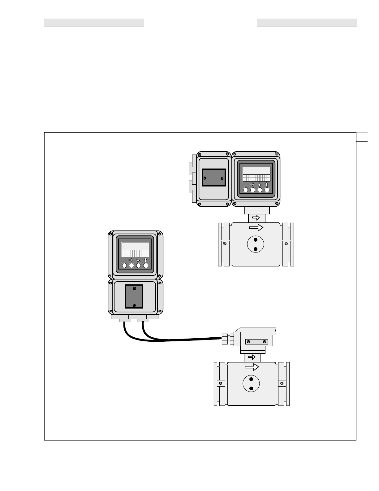
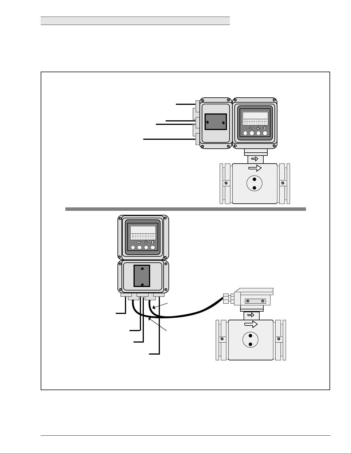
Integral Converter/Detector
Components
As shown in Figure 1, the MagneW 3000
PLUS
flowmeter includes a detector and
converter available in an integral-type
or a remote-type configuration.
With an integral-type configuration, the
converter mounts directly onto the
detector.
With a remote-type configuration, the
detector is connected by cables to the
converter which can be mounted up to
300 meters (984 feet) away, depending
on the application.
Remote Converter
8888888888888888888888
88
8888888888888888888888
Remote Detector
88
Figure 1—MagneW 3000
PLUS
Components
1/98 MagneW 3000
23441
PLUS
Specification and Application Guide 1
Page 8
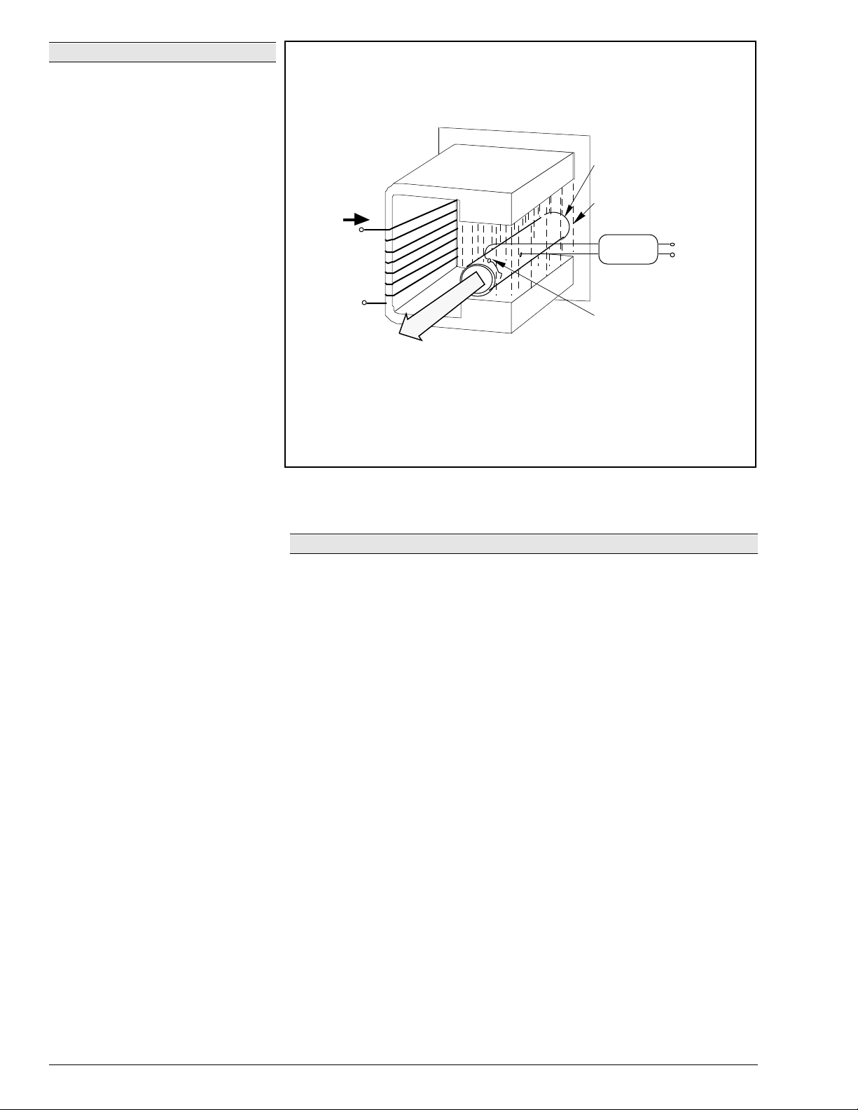
Principle of Operation
The MagneW 3000
operating principle is based on
Faraday’s Law:
PLUS
flowmeter’s
The voltage induced
across any conductor, as it moves at
right angles through a magnetic field, is
proportional to the conductor’s velocity.
The detector fits on the pipe and
measures the flow. The detector’s
excitation coils receive power from the
converter. These coils create a
magnetic field at a right angle to the flow
direction.
As the conductive liquid flows through
this magnetic field, a voltage which is
proportional to the liquid flow velocity is
produced across the electrodes. The
detector sends these voltage signals to
the converter. Refer to Figure 2.
The converter, which holds the circuitry
that calculates and displays the flow
data, converts the detector signals into
outputs for recording and control
instrumentation.
The relationship between the liquid flow
velocity and the voltage is expressed in
Faraday’s formula:
E is proportional to V x B x D
where:
E = Induced Electromagnetic
Voltage
Voltage generated by the flow of
the conductive liquid through the
magnetic field of the flowmeter.
V = Average Flow Velocity (m/s)
The average velocity of the liquid
through the cross section of the
flowmeter.
B = Magnetic Flux Density
The strength of the magnetic
field generated by the field coils.
D = Inside Diameter of the Pipe
The distance between the
electrodes which detect the
signal voltage (E) that is
generated.
This means that the voltage (E)
depends on the average flow velocity
(V), the magnetic flux density (B), and
the inside diameter of the pipe (D).
Detector
Core
Exciting
current
Power
Supply
Liquid Flow
(average velocity V)
Figure 2—Principle of Operation
Measuring Pipe
(inside diameter D)
Magnetic Field
(flux density B)
Converter
Electrode (emf E)
Output
Signal
21701
Hardware Configuration
The MagneW 3000
• an integral unit—converter mounted on detector, or
• a remote converter/remote detector.
The detector is mounted to the process piping, using one of the following types of
connections:
• wafer,
• flange,
• union,
• hose, or
• IDF or Tri-clamp.
The type of connection used is dependent upon diameter size and the application.
Where applicable, gaskets are supplied unless the grounding rings are made of
SUS material.
If using the remote converter/remote detector combination, either a wall- or pipemounting kit for the converter and cables to connect the converter and detector
are needed.
PLUS
flowmeter is available as either:
2 MagneW 3000
PLUS
Specification and Application Guide 1/98
Page 9

Features
)
Liquid crystal display with backlighting
(optional)
• In direct sunlight or in a dark room,
the backlit liquid crystal display (LCD)
can be read easily.
• Simultaneous display of
instantaneous flow volume in %,
actual flow volume in a variety of
engineering units, and indication of
total flow volume.
• When an integral model is installed on
vertical or horizontal pipes, its
display can be rotated through 90
degrees for better visibility.
Setting parameters by infrared touch
sensor (optional)
• Parameters can be set without
opening the cover of the converter.
• A special security feature has been
incorporated to prevent inadvertent
operation of the infrared touch
sensor.
Field-replaceable electrodes
Electrodes are field-replaceable.
High performance lining
• High-quality PFA lining has excellent
electrical and heat resistant
characteristics, low surface friction,
and high anti-adhesive properties.
• The PFA lining is particularly
applicable for measurement of sticky
pulps and gypsum slurries.
• PFA linings with diameter ranges from
2.5 to 600 mm (0.1 to 23.6 in.)
available, making selection of the
best lining easy for a wide variety of
applications.
• The successful, embedded punch
plate offers proven performance
under conditions of rapid thermal
change and/or negative pressure.
Rugged detector structure
• A stainless steel case is used for
diameters of 2.5 to 200 mm (0.1 to
7.9 in.).
A wide variety of piping connections
• A hose, union joint, or clamp can be
selected for very small diameter
models [diameters of 2.5 to 15 mm
(0.1 to 0.6 in.)].
• A flange structure is available for
diameters of 25 to 600 mm (1 to
23.6 in.).
• A wafer construction can also be
selected for diameters of 2.5 to
200 mm (0.1 to 7.9 in.).
• Diameters of 65, 125, and 450 mm
(2.6, 5, and 17.7 in.) have been
added to the existing product line.
Interchangeability
Can be used in combination with
previous model detectors and
converters.
Please consult your Honeywell
representative for details.
Detector
Because the detector does the actual
measuring of the flow rate, it serves as
the primary element for MagneW 3000
PLUS
flowmeters.
The detector measures the current
generated by the conductive fluid as it
moves through a magnetic field and
sends this signal to the converter.
Available models are listed in Table 1.
Converter
The converter takes the electromotiveforce signal from the detector and
converts it to the instantaneous flow
rate. That flow rate is output to the
control equipment as either an analog or
digital signal.
The converter also provides optional
pulse outputs to drive counters and
totalizers.
The converter has an optional Digital
Operator Panel (DOP) which indicates
the instantaneous flow rate or the
integrated flow rate.
Because the converter is a current
output-based device, the flowmeter can
be configured and operated using the
SFC. Or, the flowmeter can be
configured and operated locally using
the DOP.
The converter also supports the digital
enhanced (DE) mode for direct digital
communications with Honeywell’s TPS
system.
Available models are listed in Table 1.
Table 1—Available Models
DETECTORS
Model Lining Pipe Connection Diameter—mm (inches
General/watertight PFA Union/hose/clamp 2.5 to 15 (0.1 to 0.6)
General/watertight PFA
General/watertight PFA
General/submersible PFA Union/hose/clamp 15 (0.6)
General/submersible PFA
General/submersible PFA
General Integral or remote type
1/98 MagneW 3000
Polyurethane rubber
Polyurethane rubber
Chloroprene rubber
Polyurethane rubber
Polyurethane rubber
Chloroprene rubber
PLUS
CONVERTERS
Specification and Application Guide 3
Wafer 2.5 to 200 (0.1 to 7.9)
25 to 200 (1 to 7.9)
Flange 25 to 600 (1 to 23.6)
25 to 200 (1 to 7.9)
250 to 600 (10 to 23.6)
Wafer 15 to 200 (0.6 to 7.9)
25 to 200 (1 to 7.9)
Flange 250 to 600 (10 to 23.6)
25 to 200 (1 to 7.9)
250 to 600 (10 to 23.6)
Page 10
Operator Interface
The MagneW 3000
PLUS
flowmeter can
be configured, communicated with, and
operated using
• a hand-held Smart Field
Communicator (SFC),
• the flowmeter’s optional Digital
Operator Panel (DOP), and/or
• Honeywell’s TPS system.
Communications can be quickly
established with the MagneW 3000
PLUS
through the SFC. It connects to
the output terminals on the converter or
anywhere along the 4 to 20 milliampere
current line. Refer to Figure 3.
Operating parameters can be
configured or operating data can be
read by initiating simple keystroke
sequences on the SFC. As shown in
Figure 4, English language prompts in a
two-line display guide the entry of
configuration data such as:
• Pulse Parameters
• Detector Parameters
• Low Flow Cutoff
• Damping Time
• Range Parameters
• Input and Output Options
• Failsafe Mode
Pertinent operating data values are
displayed in percent or user-selected
engineering units for volume flow, mass
flow, or time.
The optional DOP, allowing local
configuration and operation of the
flowmeter, contains
• a 7-segment, 6-digit main display,
and
• a 16-digit, 2-line auxiliary display.
Analog Mode
+
Red
External
Power
Supply
24 Vdc
+
_
4-20 mA
Output 1
–
250 Ω
Black
L
SFC
(Model
STS103)
DE Mode
+
Process Manager (PM)/
Advanced Process Manager
(APM)/High-Performance
Process Manager (HPM)
internal 24/42 Vdc power
supply with 250Ω resistor
_
–
Black
L
SFC
(Model
STS103)
Figure 3—Typical SFC Connections to the 4 to 20 mA Loop
Red
+
Digital
Output 1
MagneW
PLUS
Integral Model
(or
Remote Model)
MagneW
PLUS
Integral Model
(or
Remote Model)
23442
The main display indicates the
instantaneous flow rate in percent of
span, the instantaneous actual flow
volume in selected engineering units,
and the totalized flow volume (when
pulse output is selected).
Figure 4—Typical SFC Prompts
The auxiliary display allows the operator
to monitor actions for entering/
changing configuration, operation, and
calibration data, as well as checking
diagnostic functions. These actions are
performed using the DOP’s four infrared
touch sensor keys. Refer to Figure 5.
In the DE (Digital Enhanced) mode, the
flowmeter can communicate digitally
with Honeywell’s TPS, and through a
custom field termination assembly
(FTA) to Allen-Bradley controllers.
Figure 5—Digital Operator Panel Display (configured for % flow range)
4 MagneW 3000
DE CONF SFM 1001
F/S = B/O HI
23443
Main
Display
%00.
0.00 m3/h
Auxiliary
0000123456 TOTAL
PLUS
Specification and Application Guide 1/98
Display
23444
Page 11
Diagnostics
k
k
In the event of a malfunction,
diagnostic messages speed up the
troubleshooting process. Messages are
available locally when using the optional
DOP and via the SFC.
When operating in the DE mode, similar
interface operations are possible
through displays at the Universal
X
Station
Station (GUS) in the TPS system.
(UXS) or the Global User
Digital Communications
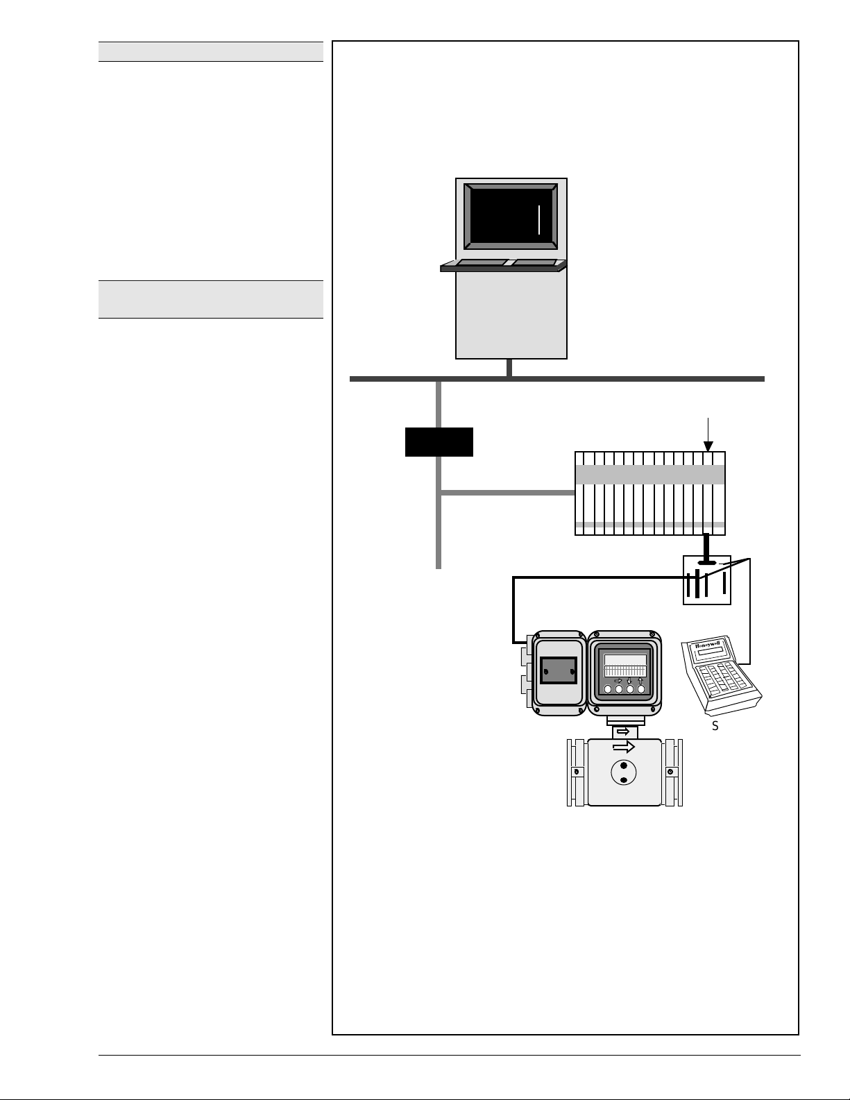
Summary
The SFC (model STS103) can be used
to “talk” to a flowmeter operating in
either the analog or the DE (Digital
Enhanced) mode. The SFC is
connected across the current line at the
flowmeter or any convenient point in the
line. See Specification 34-ST-03-55 for
more details about the SFC.
To “talk” to a flowmeter through displays
at the Universal Station or GUS, the
transmitter is connected to a Smart MV
Transmitter Interface Input/Output
Processor (STI IOP) in the Process
Manager (PM), Advanced Process
Manger (APM), or High-Performance
Process Manager (HPM) through an
FTA as shown in Figure 6. The flowmeter
must be in the DE mode to communicate
with the STI IOP.
Also, through a custom FTA the
flowmeter, in the DE mode, can
communicate with Allen-Bradley
controllers.
Universal
Station
or Global
User
Station
(GUS)
Network
Interface
Module
Universal
Networ
Control
DE/ Digital
Communications
Process Manager or
Advanced Process Manager
(or High-Performance Process
Manager)
Link
TPS Process Networ
Smart MV Transmitter
Interface I/O Processor
STI FTA
L
SFC (Model
MagneW
Integral Model
(or
Remote Model)
Figure 6—Typical MagneW 3000
1/98 MagneW 3000
PLUS
Specification and Application Guide 5
PLUS
PLUS
Communications Hierarchy for TPS
STS103)
23445
Page 12
Summary of MagneW 3000
PLUS
Features
Table 2 provides a summary of major MagneW 3000
Table 2—Summary of Major MagneW 3000
Feature Function
Operating principle based on Faraday’s Law Provides accurate and reliable measurement of process fluid flow rate.
Flange-mounted detector Provides a variety of process connections to match installation
4 to 20 milliampere signal or digital-enhanced
output
SFC and TPS communications Provide means to configure, operate, and troubleshoot MagneW through
Optional built-in counter for pulse output
models
Optional 1- or 2-contact input • External 0% lock input: Locks the flow rate signal (display, analog
PLUS
features and functions.
PLUS
Features
The unit of flow indication can be in percentage, volume flow, mass flow, or
time.
requirements.
Provides signal proportional to flow measurement in analog or digital form
depending upon configuration.
SFC and Universal Station or GUS in TPS system.
• Totalizer: Depending on pulse direction setting, it totals one count at a
time, for forward and reverse flows.
• Totalizer with preset function: A preset value (target total) can be set
between 000000 and 999999. Each forward and reverse flow signal is
counted.
• Forward/reverse flow difference totalizer: The difference in flow volumes
in the forward and reverse directions is calculated and counted.
output, and pulse output) at 0%.
• External zero adjustment input: Allows a zero point adjustment from a
remote location.
• External range switching input: Factory setting is
– Range No. 1 or forward direction when opened
– Range No. 2 or reverse direction when closed.
• Built-in counter reset input (optional for pulse output model): Reset
occurs when contact is ON for 0.2 seconds or more. Counting starts
from counter reset value when contact turns OFF.
Optional 1- or 2-contact output • Alarm contact output: An alarm is output when one of the following
abnormal states occurs.
– flow value alarm
– self-diagnosis—coil disconnection, ROM error, RAM error, NVM error,
ADC error, or
– empty pipe detection.
• Range switching output: Factory setting is
– Range No. 1 or forward direction—when open
– Range No. 2 or reverse direction—when closed
• Counter preset status output (for pulse output model): Activates when
the built-in counter reaches the preset value.
• Self-diagnosis alarm output: Activates when the self-diagnosis function
detects an abnormality.
• Empty pipe detection alarm output (with empty-status detection):
Activates when the fluid level in the detector goes below the electrode
level. Alarm is available only when the electrical conductivity of the
liquid is greater than 150µS/cm.
• High/Low limit alarm: Activates when the flow volume exceeds the set
upper and lower limit values.
• Two-stage flow value alarm output (with two contact outputs): An alarmactuating contact is output when the simultaneous flow value exceeds
the set two upper limits (H and HH) or the two lower limits (L and LL).
6 MagneW 3000
PLUS
Specification and Application Guide 1/98
Page 13
Wiring Summary
External excitation and signal cables are required when connecting the remote
detector/converter model.
Figure 7 provides an overview of possible wiring requirements for either model.
Integral Converter/Detector
Power supply
Vac or 24 Vdc
Pulse output
Contact input/output
4 to 20 mA/DE output
8888888888888888888888
88
Remote Converter
and
Remote Detector
Power supply
Vac or 24 Vdc
Pulse output
Contact input/output
4 to 20 mA/DE output
Figure 7—Overview of MagneW 3000
8888888888888888888888
PLUS
Wiring Requirements
88
Signal cable
Excitation cable
23446
1/98 MagneW 3000
PLUS
Specification and Application Guide 7
Page 14

Electrical Connection Considerations
For electrical connections of the
converter/detector the following should
be checked:
• Cable types
• Laying of cables
• Cable lengths
• Grounding
Cable Types
The standard cables for the instrument
are as follows:
Signal cable:
•
double-shielded cable
Excitation cable:
•
cabtyre cable
If standard cables are unavailable,
contact Honeywell for
recommendations.
Laying of Cables
• Do not lay the cables near a motor, a
transformer, or a large-current cable
which may cause induction noise.
Lay the cables 1 meter (3.3 feet) or
more away from heavy-duty power
cables.
• Lay the signal cable in a metallic
conduit, a flexible tube, or a duct,
separately from the excitation current
cable or any other power cables.
• Wire with electrical tube and duct to
keep out water and protect the wire
from external damage. Lay the tube
so that no water gets into the unit.
• Use a waterproof gland at the conduit
connection.
• Do not employ any junction point for
connection of the signal cable or the
exciting cable between the detector
and the converter. When it is
unavoidable to employ a junction
point, use Cable Junction Box (Part
No. 80720002-000) which has been
designed specifically for this
purpose.
• Do not short the excitation current
terminals X and Y of the converter.
2-core individually
2-core chloroprene
Cable Lengths
• The length of the cable between the
detector and the converter depends
on the electrical conductivity (µS/m)
of the fluid to be measured. (Refer to
Figure 9 on page 10.)
In general, the electrical conductivity
of potable water or sewage water is of
a level of 10000 µS/m (100 µΩ/cm).
Therefore, for a detector of 15 mm
(0.6 in.) diameter or over, the
maximum allowable cable length is
300 meters (984 feet).
• Signal Cable
If a signal cable is required to be laid
more than 500 meters (1640 feet),
select a cable cross section so that
the voltage drop in the cable does not
exceed 5V.
To calculate the excitation cable
cross section area, use the following
formula:
A (cross section area: mm
35.6 x L (cable distance: m) x 0.4 (A)
1000 x 5 (V)
• Current output cable (4-20 mA)
The allowable current output load of
the converter is 0 to 600Ω. The sum of
the cable resistance plus load
resistance must be within this range.
With a 2 mm
cable resistance for both-ways
between 1 km (3.281 ft.) distance is
approximately 20Ω. When the
receiver load is 400Ω, the current
output cable can be extended up to 10
km (6.2 miles).
• Pulse output cable
Can be extended up to 1 km
(3,281 ft.).
Grounding
• The grounding circuit should be less
than 100Ω.
• At the converter side, ground the
meter at the E terminal of the terminal
block or the ground terminal of the
case. The E terminal and the ground
terminal are mutually connected in the
unit.
2
(0.003 in2) cable, the
2
) =
8 MagneW 3000
PLUS
Specification and Application Guide 1/98
Page 15
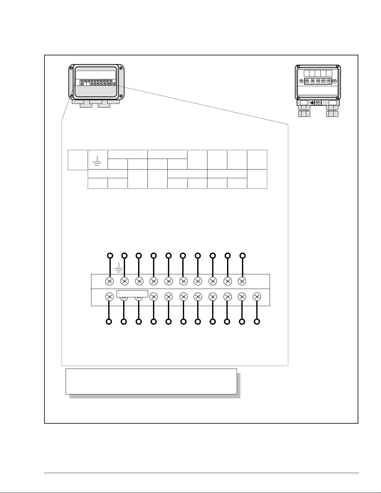
Terminal Connections
Figure 8 shows typical wiring connections for both the integral and remote types.
REMOTE CONVERTER
ABCXY
TERMINAL CONNECTOR BOX
SIG EX
REMOTE
DETECTOR
TERMINALS
STATUS IN
STATUS IN1
OR
STATUS OUT2
OR
*
STATUS OUT
STATUS IN2
STATUS OUT1
—1-contact input and 1-contact output
—2-contact inputs
—2-contact outputs
**
E
+–+–
POWER
LN
Not used
XY
Contact input,
Class 3 grounding
input 1, or output 2
Contact output,
SB SA C A
I.OUTP.OUT
+–+–
Flow rate
input 2, or output 1
signal input
B
E SB SA C A
Not used
Power supply
AC or DC 24V
+–+–
WARNING
LN
XY
Excitation output
Pulse output
NOTE: FOR INTEGRAL CONVERTER/DETECTOR:
Terminal symbols X, Y, SB, SA, A, B, C, and E are not indicated
because these terminals are not used.
Figure 8—Typical Wiring Connections for the MagneW 3000
+–+–
Current output
PLUS
Remote and Integral Flowmeters
B
Flow rate
signal input
Not used
23447
1/98 MagneW 3000
PLUS
Specification and Application Guide 9
Page 16
Cabling for Remote Detector/Converter
Honeywell offers the excitation and signal cables as a set under a separate model
number (Model Number KIW-XXX-XXX). Commercially available cables can be
used. The selection of the signal cables depends on certain conditions:
• fluid conductivity,
• length of cable, and
• diameter of the detector.
Figure 9 shows the relation between fluid conductivity and cable length.
The shaded portions are the
areas where commercially
available cables or cables
without shield drives can be
used.
Cable
Length
mft
300 984
200 656
100 328
50 164
20 65.6
15 49.2
10 32.8
5 16.4
2 6.6
1 3.3
mft
300 984
200 656
100 328
Detector Sizes: 2.5 and 5mm (0.1 and 0.2 in)
3 5 10 20 50 100 200 500 1000
Electrical Conductivity (µΩ/cm)
Detector Sizes: 10mm (0.4 in) and greater
Cable
Length
NOTE: Empty pipe detection alarm is available only when the
electrical conductivity of the fluid is greater than 150 µS/cm.
Figure 9—Cable Length Versus Fluid Conductivity
50 164
20 65.6
15 49.2
10 32.8
10 MagneW 3000
5 16.4
2 6.6
1 3.3
3 5 10 20 50 100 200 500 1000
Electrical Conductivity (µΩ/cm)
PLUS
Specification and Application Guide 1/98
23448
Page 17
Ranging Function
The range function allows the operator to define the basic operating
characteristics of the flowmeter. Table 3 explains the various function options
that are available.
Table 3—Summary of Range Function Options
Analog
Type Description Output Pulse Display
Single Range • Direct flow only with
one 4 to 20 range
Forward:
4-20 mA dc
Reverse:
Proportional Positive No effect
Not delivered Minus
–20%
(0.8 mA)
Direct, Dual
Range, Auto
Selection
• Direct flow only with
two ranges
• Switching between
Both 4 to
20 mA dc
Pulse weight for
both ranges is
the same
measuring ranges is
automatic
(Hysteresis is
illustrated in Figure
10.)
Direct, Dual
Range, External
Selection
• Direct flow only with
two ranges
• Switching between
Both 4 to
20 mA dc
Pulse weight for
both ranges is
the same
ranges is done
externally
Direct/Reverse,
Dual Range,
Auto Selection
• Direct and reverse
flow with two ranges
• Switching between
measuring ranges is
Both 4 to
20 mA dc
Pulse weight is
same
regardless of
flow direction
automatic
(Hysteresis
illustrated in Figure
11)
Minus sign
appears
when flow is
in reverse
direction
Contact
Input Output
No effect Factory setting
1st range: open*
2nd range:
closed*
Range select
1st range:
open
2nd range:
closed
Factory setting
1st range: open*
2nd range:
closed*
contact outputs
(optional)
No effect Factory setting
direct: open*
reverse: closed*
Direct/Reverse,
Dual Range,
External
Selection
• Direct and reverse
flow with two ranges
• Switching between
ranges is done
externally
*Reverse setting is also possible.
Output
20 mA
4 mA
Adjustable by 0-20%
Figure 10—Direct Direction, Automatic
Dual Range Transfer Hysteresis
Input
23449
Both 4 to
20 mA dc
Pulse weight is
same
regardless of
flow direction
Minus sign
appears
when flow is
in reverse
direction
Output20 mA
Reverse
direction
With respect to direct
direction range,
adjustable by 0-20%
Figure 11—Direct/Reverse Transfer Hysteresis
Range select
direct: open
reverse:
closed
Factory setting
direct: open*
reverse: closed*
contact output
(optional)
Direct
direction
Input
With respect to reverse
direction range,
adjustable by 0-20%
23450
1/98 MagneW 3000
PLUS
Specification and Application Guide 11
Page 18
Selection of Corrosion-
Resistant Materials
The corrosiveness of fluids used under
practical conditions may vary according
to the type and amount of impurities
present, the operating temperatures,
the variances in flow rate, and the
concentration of fluids.
Selection of Lining Materials
The lining materials for use in the
MagneW 3000
PFA, alumina ceramic, polyurethane
rubber, and chloroprene rubber. Their
general characteristics are shown in
Table 4.
PLUS
include Teflon
Selection of Materials for Electrodes
Selection of Ground Ring Material
The same material for ground rings as
for electrodes should be selected since
both come in contact with fluids.
and Wet Contact Rings
The general characteristics of electrode
materials is shown in Table 4.
Table 4—Characteristics of Wet Contact Materials
Material Main Component Characteristics Recommended Environment
Lining Materials
Polyurethane rubber Polyurethane A synthetic elastic rubber. Excellent
Teflon PFA Tetrafluoroethyl
Ceramic Alumina ceramic
ene resin
Al
: 99.7%
2O3
abrasion resistance. Little chemical
resistance.
A synthetic polymer containing fluorine
(F) in the molecule. Resistant to almost
all chemicals except for hightemperature fluorine, molten alkalis,
and some halogen compounds.
Excellent heat resistance together with
a low friction characteristic and nonadhesiveness.
Excellent friction resistance. Suited for
high temperatures and high pressures.
Chemical resistance is slightly lower
than that of Teflon PFA. Weak to alkali
fluids.
Temperature:
+122°F)
Pressure:
NOTE: Provides heat resistance in hot
atmospheres.
–40 to +50°C (–40 to
426 psi maximum
Temperature:
–40 to +100°C (–40 to +212°F) for
diameters 2.5 to 10 mm (0.1 to 0.4 in.)
–40 to +160°C (–40 to +320°F) for
diameters 15 to 200 mm (0.6 to 7.9 in.)
–40 to +100°C (–40 to +212°F) for
diameters 2.5 to 10 mm (0.1 to 0.4 in.)
Pressure:
Temperature:
(–40 to +356°F)
Pressure:
Refer to Table 5, page 15.
–40 to +180°C
1 to 40 kg/cm
14 psi maximum
2
Chloroprene rubber Chloroprene The friction and chemical resistances
are almost comparable to those of
polyurethane rubber.
Electrode Materials
SUS316L Cr : 17%
Ni : 13%
Mo : 2.25%
C : <0.03%
Fe : Remainder
Titanium Ti : >99.3% Resistant to corrosion in an oxidizing
Hastelloy C-276 Mo : 16%
Cr : 16%
Fe : 5%
W : 4%
Ni : Remainder
Resistant to corrosion in a weak alkali
or acidic atmosphere.
Unusable in inorganic and organic
acids, chlorides, etc.
atmosphere.
In particular, usable in the presence of
chlorine ions. Unusable in sulfuric acid,
nitric acid, etc.
(The empty-detection function of the
converter cannot be used.)
A wide range of uses since it is usable
in moderately oxidizing and reducing
atmospheres.
Weak to sulfides, sulfuric acid, etc.
Temperature:
Pressure:
Water (tap and sewage) and weak alkalis
(such as caustic soda of 50% or less)
A variety of chloride solutions
(ammonium chloride, potassium
chloride, ferrous chloride, etc.), sea
water, etc.
A variety of organic and inorganic acids,
alkalis, etc.
–10 to +70°C (14 to 158°F)
142 psi maximum
12 MagneW 3000
PLUS
Specification and Application Guide 1/98
Page 19
Table 4—Characteristics of Wet Contact Materials, continued
Material Main Component Characteristics Recommended Environment
Electrode Materials (continued)
Tantalum
For Teflon PFA
lining:
Ta : >99.5%
For ceramic use:
Ta : 90%
W : 10%
Resistant to corrosion in strongly
oxidizing and reducing atmospheres,
but unusable in alkalis, fluorides, and
fuming sulfuric acid.
Because an insulating film may form on
these electrodes, pay special attention
to process conditions when selecting
this material.
(The empty-detection function of the
converter cannot be used.)
Concentrated hydrochloric acid, sulfuric
acid, nitric acid, aqua regia, etc.
Platinum-iridium alloy Pt : 90%
Ir : 10%
Tungsten carbide Highly abrasion-resistant and causes
Nickel Highly corrosion-resistant against
Zirconium Corrosion-resistant against various
Resistant to corrosion in almost all
acids and alkalis except for aqua regia
and ammonium salts. Very expensive.
less slurry noise. Cannot be used for
corrosive fluids.
strong alkali fluids, especially against
caustic soda and fluoric acid as
compared with corrosion resistances of
other metals.
chemicals, especially against sulfides.
Application Assistance
While the technical information provided in this guide is usually adequate for
sizing a meter for a particular application, Honeywell has Application Assistance
available. An Application Data Sheet (36-KI-08-01) is included at the end of this
document. When completed it provides the information necessary for a thorough
review by our Field Instrument Application Engineers. Using your application and
installation information, process fluid data, and cost and operation objectives,
these engineers will apply their wide industry experiences and various application
software programs to assist in determining the most cost-effective flow solution
available. To use this Honeywell service, please complete the Application Data
Sheet and forward it to your Honeywell Representative for submission to Field
Instrument Application Engineering.
Phosphoric acid, nitric acid, fluoric acid,
hydrochloric acid, sulfuric acid, alkalis,
etc.
Cement slurry, muddy slurry, filthy
slurry, earth/sand slurry, etc.
Caustic soda, fluoric acid, alkali fluids,
etc.
Copper sulfide, formic acid, potassium
hydroxide, etc.
1/98 MagneW 3000
PLUS
Specification and Application Guide 13
Page 20

Installation Planning Considerations
w
e
The MagneW 3000
and operation, the following installation conditions should be reviewed:
• Environmental conditions
• Fluid to be measured
• Measured liquid flow conditions
• Detector location in piping
• Clearance for maintenance and inspection
PLUS
planning considerations are summarized in Table 5. To ensure proper flowmeter selection
Table 5—Summary of Installation Considerations
Factor Consideration
Environmental conditions The following should be considered when installing the MagneW 3000
• The ambient temperature should be within the following ranges:
–
Integral model:
–25 to +60°C (–13 to +140°F)
–
Remote converter:
–25 to +60°C (–13 to +140°F)
–
Remote detector:
PLUS
.
PFA lining:
–30 to +80°C (–22 to +176°F)
Polyurethane rubber or Chloroprene rubber lining:
–30 to +60°C (–22 to +140°F)
• Whenever possible, the flowmeter should not be exposed to direct sunlight, rain, or other
unfavorable weather.
• The flowmeter should be installed as far from any pump in the line as practical, so that the flo
does not pulsate.
• The flowmeter must not be subjected to severe vibration, as equipment damage could result.
• The flowmeter must not be subjected to a highly corrosive atmosphere, as equipment damag
could result.
• The flowmeter must be installed sufficiently apart from high-current power lines, motors,
transformers, or any other source of electromagnetic interference.
14 MagneW 3000
PLUS
Specification and Application Guide 1/98
Page 21
Table 5—Summary of Installation Considerations, continued
.
Factor Consideration
Fluid to be measured The fluids to be measured must fall within MagneW 3000
• electrical conductivity—3µS/cm or greater
• temperature
• pressure
kPapsig This area (120 to 160°C/
+2937
+426
+1958
+284
Pressure
+142
LEGEND
+979
-14
-97
-40 0 +50 +100 +160+120
°C
-40 +32 +122 +212 +320+248
°F
Code Liner
Polyurethane
Rubber
Teflon PFA
Teflon PFA
Teflon PFA
Chloroprene
Rubber
Temperature (Degrees)
Detector Size
mm (in.)
25 to 200
(1 to 7.9)
2.5 to 10
(0.1 to 0.4)
15 to 200
(0.6 to 7.9)
250 to 600
(9.8 to 236)
250 to 600
(9.8 to 23.6)
PLUS
specifications for:
248 to 320°F) applies to
remote detectors only with
PFA liner and detector
size 15 to 200 mm (0.6 to
7.9 inches)
Temperature Range
°C °F
–40 to 50
–40 to 100
–40 to 160
–40 to 120
–10 to 70
–40 to 212
–40 to 320
–40 to 248
14 to 158
–40 to 122
23451
Measured liquid flow
conditions
The following liquids may not be successfully measured by MagneW 3000
PLUS
, even if their
conductance, temperature, and pressure fall within its limits.
• Fluids that have sufficient conductivity at high temperatures but not at room temperature,
approximately 20°C (68°F).
EXAMPLE: fatty acids and soap
• Fluids that contain surface active agents
EXAMPLE: shampoo, rinse, and soap material liquids
• Conductive adherents
EXAMPLE: deposition of rosin plus conductive material
• Insulating adherents
EXAMPLE: oil, kaolinite, kaolin, and calcium stearate
When determining the piping location for the flowmeter, make sure the measured liquid flow
meets the following conditions:
• The fluid has the required conductivity for measurement and the distribution of conductance
is uniform.
• The fluid is electrochemically uniform. For example, if two fluids are mixed at an upstream
point, the two fluids should be uniformly mixed by the time they reach the measurement point
• The distribution of suspended solids is uniform.
1/98 MagneW 3000
PLUS
Specification and Application Guide 15
Page 22
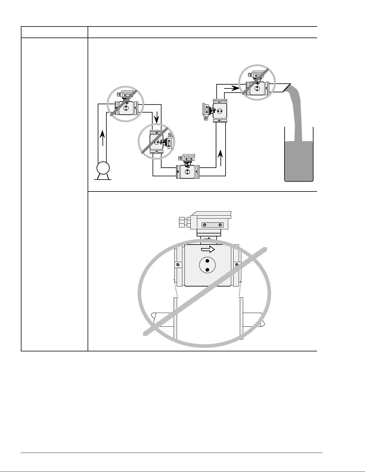
Table 5—Summary of Installation Considerations, continued
Factor Consideration
Detector location in
piping
The detector should be installed in the pipeline where it will always be filled with the measured
fluid.
Not filled with liquid
Air may be entrapped
May not be
filled with liquid
Good
location
Pump
Good location
23452
The face-to-face space between the flanges must be sufficient for the given detector size.
Never force the detector into an insufficient face-to-face space.
16 MagneW 3000
23453
PLUS
Specification and Application Guide 1/98
Page 23
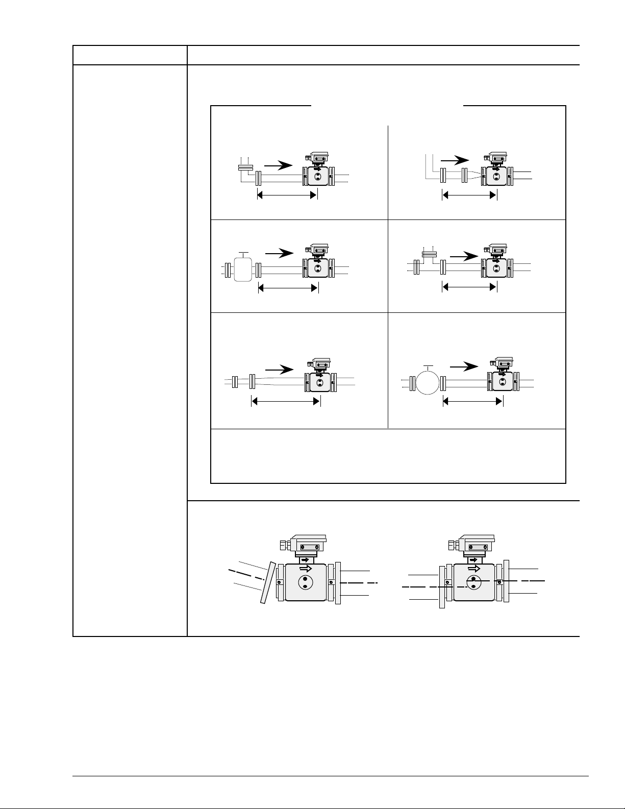
Table 5—Summary of Installation Considerations, continued
r
Factor Consideration
Detector location in
piping (continued)
Straight pipe sections must be provided on the upstream and downstream sides of the detector
as shown.
UPSTREAM SIDE
(D = Nominal diameter of detector)
90-degree elbow
5D or greater
Sluice valve (full open)
5D or greater
Expansion pipe with cone angle 15 degrees
or more (if the cone angle is less than 15
degrees, can be regarded as a straight pipe
section)
Reducer pipe (can be regarded
as a straight pipe section)
5D or greater
Tee
5D or greater
Valve other than a sluice type
5D or greater
10D or greater
DOWNSTREAM SIDE
(D = Nominal diameter of detector)
2D or greater (minimum 2D if drift current or the like is possible)
23454
The process piping with flanges must be straight and centered. Below are examples of imprope
alignments.
Tilted pipe
Off-centered
23455
1/98 MagneW 3000
PLUS
Specification and Application Guide 17
Page 24
Table 5—Summary of Installation Considerations, continued
Factor Consideration
Clearance for
maintenance
Sufficient space must be provided for maintenance of the electrodes and inspection of the
terminals, and for operation of the converter with an integral type flowmeter.
Suggested minimum clearances are provided below.
500 mm
19.7 in.
400 mm
15.8 in.
500 mm
19.7 in.
400 mm
15.8 in.
Integral type
400 mm
15.8 in.
400 mm
15.8 in.
Remote detector
23456
18 MagneW 3000
PLUS
Specification and Application Guide 1/98
Page 25

Specifications
Table 6 summarizes pertinent specification data for the MagneW 3000
Table 6—Specifications for MagneW 3000
PLUS
Performance
Accuracy Refer to the following tables.
Diameters 2.5 mm to 15 mm (0.1 in. to 0.6 in.):
Vs (m/s) Accuracy at Vs ≥40% Accuracy at Vs ≤ 40%
1.0 ≤ Vs ≤ 10 ±0.5% of indicated value ±0.2% of Vs
0.1 ≤ Vs ≤ 1.0 ±(0.1/Vs + 0.4%) of indicated ±0.4 (0.1/Vs + 0.4)% of Vs
value
Diameters 25 mm to 600 mm (1 in. to 23.6 in.):
Vs (m/s) Accuracy at Vs ≥20% Accuracy at Vs ≤20%
1.0 ≤ Vs ≤ 10 ±0.5% of indicated value ±0.1% of Vs
0.1 ≤ Vs ≤ 1.0 ±(0.1/Vs + 0.4%) of indicated ±0.2 (0.1/Vs + 0.4)% of Vs
value
Design
Flow Velocity Ranges 0-0.1 m/s to 0-10 m/s (0-0.3 ft/s to 0-30 ft/s)
The range can be set locally through the DOP or remotely through the SFC.
See Table 7 for minimum and maximum ranges by diameter.
PLUS
.
Upper limit value of Vs = set velocity range
Upper limit value of Vs = set velocity range
Electrical Conductivity of
Liquid
Liquid Pressure and
Temperature Ranges for
Detector
Damping Time Constant Variable from 0.5 to 199.9 seconds.
Low Flow Cutoff Current output corresponding to 0-10% of set range (variable integer)
Dropout Pulse output corresponding to 0-10% of set range (variable integer) for 20 kHz maximum
Lightning Protection 12 kV, 1000A
Power Failure EEPROM retains data record of total flow volume when pulse output is used (retention period
Input (Transmitter) Detector flow signals plus external selections that drive a semiconductor or no-voltage open-
300 microsiemens/m (3 micromhos/cm) minimum.
See Table 5, Page 14.
Incorporated into the power source and external input and output terminals.
approximately 10 years).
close contact signal for any one of the following functions:
External 0% lock:
•
pulse output via contact input.
External automatic zero adjustment:
•
External range changeover:
•
Built-in counter reset (optional for pulse output model):
•
the built-in counter by contact input.
Enables 0% stop of the flow indication, analog output, digital output, and
Adjusts the zero point by contact input.
Switches dual range or forward/reverse range by contact input.
Resets the total flow volume value of
1/98 MagneW 3000
PLUS
Specification and Application Guide 19
Page 26

Table 6—Specifications for MagneW 3000
PLUS
, continued
Design (continued)
Outputs (Transmitter) • Detector’s coil excitation current
Current output without SFC communications requirement:
•
load with external 24 Vdc power supply.
Current output with SFC/DE communications requirement:
•
ohms load with an external 24 Vdc power supply.
1460
620
300
Load Resistance (Ω)
250
•
Contact output:
following condition states:
– Alarm actuating contacts for
Self-diagnosis alarm —Outputs an alarm-actuating contact when the self-diagnosis function
detects an error.
No-load detection alarm (with empty-status detection) —Outputs an alarm-actuating
contact when the fluid level in the detector goes below the electrode level.
Upper/lower flow limit value alarm —Outputs an alarm-actuating contact when the flow
volume exceeds the upper/lower limit values.
Two-stage flow value alarm (with two contact outputs) —Outputs an alarm-actuating contact
when the flow value exceeds the two upper limits (H and HH) or the two lower limits (L and
LL).
– Range identification output—Outputs a contact for large and small ranges, forward and
reverse direction ranges.
– Counter preset status (for pulse output model)—Outputs a contact when the built-in
counter reaches the preset value.
For a maximum external load of 30 Vdc/200 mA, indicating any one of the
Load Resistance (Ω) =
16.0 24.0 45
Supply Voltage (Vdc)
4 to 20 mA dc into a 0 to 600 ohms
4 to 20 mA dc into a 250 to 1460
Supply voltage 8.5
0.025
Operating
Range
21703
Display Display card can rotate 90° for installation on vertical pipe.
Backlit liquid crystal display (LCD).
Display board:
One line with six 7-segmented digits—Main display
Dot matrix, two lines with 16 columns—Auxiliary display
Display contents:
• instantaneous flow rate in percent
• instantaneous actual flow rate in a variety of engineering units
• total volume (with pulse output model)
• engineering data
Operator Interface Four infrared touch sensor keys OR
Hand-held communicator with keyboard and LCD. Connects anywhere in the 4-20 mA output line.
Mounting
Converter:
• Integral mounts directly on detector
• Remote mounts on wall or 2-inch pipe
Detector:
20 MagneW 3000
A variety of piping connections are offered–flange, wafer, hose, sanitary coupling, etc.
PLUS
Specification and Application Guide 1/98
Page 27

Table 6—Specifications for MagneW 3000
Flange Rating •
25 to 50 mm (1 to 2 in.) diameters:
150, ANSI 300, DIN PN10, DIN PN16, DIN PN25, DIN PN40
80 to 200 mm (3.2 to 7.9 in.) diameters:
•
ANSI 150, ANSI 300, DIN PN10, DIN PN16, DIN PN25, DIN PN40, JIS G3451 F12
250 to 600 mm (9.8 to 23.6 in.) diameters with PFA lining:
•
JPI3 00, ANSI 150, ANSI 300, DIN PN10, DIN PN16, DIN PN25, JIS G3451 F12
250 to 600 mm (9.8 to 23.6 in.) diameters with chloroprene rubber lining:
•
ANSI 150, DIN PN10, JIS G3451 F12
PLUS
, continued
Design (continued)
JIS 10K, JIS 16K, JIS 20K, JIS 30K, JPI 150, JPI 300, ANSI
JIS 10K, JIS 20K, JIS 30K, JPI 150, JPI3 00,
JIS 10K, JIS 16K, JIS 20K, JPI 150,
JIS 10K, JPI 150,
Structure
Finish
Color
Material
Converter:
• Converter can rotate 180°.
NEMA 4X, IEC IP66, JIS C 0920 waterproof model
Detector:
• NEMA 4X, IEC IP67, JIS C 0920 watertight model
• NEMA 6, IEC IP68, JIS C 0920 submersible model
Electrode
• Watertight—External insertion (electrode can be removed)
• Submersible—Internal insertion (electrode cannot be removed)
Converter:
acrylic resin
Detector:
• Watertight:
2.5 to 200 mm (0.1 to 7.9 in.) diameters, terminal box only of remote model—corrosionpreventive acrylic resin
250 to 600 mm (9.8 to 23.6 in.) diameters, terminal box of remote model and case of
remote/integral models—Corrosion-preventive polyurethane resin
•
Submersible:
15 to 200 mm (0.6 to 7.9 in) diameters, terminal box only; and 250 to 600 mm (9.8 to 23.6 in.)
diameters, terminal box and case—Corrosion-preventive tar epoxy
Converter:
light beige
Detector:
• Watertight: light beige
• Submersible: black
Converter:
• Main body—Aluminum alloy
• Display cover—Tempered glass, 5 mm thick; aluminum alloy
Detector:
• Flange
25 to 65 mm (1 to 2.6 in.) diameters—SUS304 stainless steel
80 to 600 mm (3.2 to 23.6 in.) diameters—carbon steel plus corrosion-preventive coating
• Case
2.5 to 15 mm (0.1 to 0.6 in) diameters—SCS13 stainless steel
25 to 200 mm (1 to 7.9 in.) diameters—SUS304 stainless steel
250 to 600 mm (9.8 to 23.6 in.) diameters—SS400 carbon steel
• Terminal box—Aluminum alloy (remote model)
1/98 MagneW 3000
PLUS
Specification and Application Guide 21
Page 28

Table 6—Specifications for MagneW 3000
PLUS
, continued
Design (continued)
Wetted Materials
Electrical Conduit 1/2 inch NPT, G1/2, CM20, Pg13.5 internal threads, optional plastic and brass waterproof glands
Lining:
• 2.5 to 600 mm (0.1 to 23.6 in.) diameters—PFA
• 25 to 200 mm (1 to 7.9 in.) diameters—polyurethane rubber
• 250 to 600 mm (9.8 to 23.6 in.) diameters—chloroprene rubber
Electrode:
Platinum/Iridium
Ground ring:
Union joint for diameters 2.5 to 15 mm (0.1 to 0.6 in.):
Hose for diameters 2.5 to 15 mm (0.1 to 0.6 in.):
IDF clamp:
Tri-clamp:
Gasket:
Tantalum, and Platinum. For ground rings made of SUS316, gaskets are supplied by customer;
non-rubber, such as PTFE or joint sheet, is recommended.
O-ring:
(G1/2 only)
SUS316L, Hastelloy C, Titanium, Zirconium, Tantalum, Tungsten-Carbide,
SUS316, Hastelloy C, Titanium, Zirconium, Tantalum, Platinum
SUS316
SUS316
SUS316
SUS316
PTFE gaskets are supplied with ground rings of Hastelloy C, Titanium, Zirconium,
Viton rubber (with union joints)
Nuts and Bolts For wafer construction models only
Electrical Connection
S20C carbon steel, SUS304 stainless steel
Integral:
M4-12P screw terminals
Remote:
• Converter—M4-19P screw terminals
• Detector—M4-5P screw terminals
Cables
Cable Length 300 meters (984 feet) maximum
Grounding Category 3
Dimensions See Figures 12 through 20, as applicable.
Weight
Signal cable:
Coil excitation current cable:
100 ohms maximum ground resistance
Converter:
Detector:
2-core individually double-shielded cable
2-core chloroprene cabtyre cable
3.7 kg (8.2 lbs)
Refer to Table 8, 9, or 10, as applicable.
22 MagneW 3000
PLUS
Specification and Application Guide 1/98
Page 29

Table 6—Specifications for MagneW 3000
PLUS
, continued
Environmental and Operating Conditions
Ambient Temperature
Relative Humidity 5 to 100%
Power Requirements •
Power Consumption 13W (17 VA)
Approval Bodies Model No. Approval Body Approval Type and Classification
CE Mark Conformity
(Europe)
Converter:
–25 to +60°C (–13 to +140°F)
Detector:
• Integral model: –25 to +60°C (–13 to +140°F)
• Remote model, PFA lining: –30 to +80°C (–22 to +176°F)
• Remote model, polyurethane rubber lining/chloroprene rubber lining:
–30 to +60°C (–22 to +140°F)
Voltage (Vac) ±10%:
Voltage (Vdc) ±10%:
•
Frequency:
•
MGG14C CSA and FM Nonincendive – Class I, II, III, Division 2,
Remote Converter Groups A, B, C, D, E, G
MGG17D, F, U CSA and FM Special Protection – Class I, II, III, Division 1,
Remote Detector Groups B, C, D, E, F, G
MGG18D, F, U CSA and FM Nonincendive – Class I, II, II, Division 2,
Remote Detector Groups A, B, C, D, F, G
(Water Tight)
MGG19D, F, U CSA and FM Nonincendive – Class I, II, III, Division 2,
Remote Detector Groups A, B, C, D, F. G
(Submersible)
MGG14C (Converter) CSA and FM Nonincendive – Class I, II, III, Division 2,
MGG18D, F, U Groups A, B, C, D, F, G
Integral Unit
MGG16D, F, U CENELEC EEx de ia II CT4
Remote Detector
MagneW 3000
for EN 50082-2-1995.
50 or 60 Hz
PLUS
100, 110, 115/120, 200, 220, 230/240
24
meets the emission limits for EN 50081-1-1993 and the immunity standards
1/98 MagneW 3000
PLUS
Specification and Application Guide 23
Page 30

Table 7—Minimum and Maximum Ranges
Diameter
mm (inches)
2.5
(0.1)
5
(0.2)
10
(0.4)
15
(0.6)
25
(1)
40
(1.6)
50
(2.0)
65
(2.6)
80
(3.1)
100
(3.9)
Minimum Range—m
[Minimum constant flow speed of
0 to 0.1 m/s (0 to 0.3 ft/s)]
0 to 0.00177
(0 to 0.625)
0 to 0.00707
(0 to 0.2498)
0 to 0.0283
(0 to 1)
0 to 0.0636
(0 to 2.24)
0 to 0.177
(0 to 6.25)
0 to 0.452
(0 to 15.97)
0 to 0.707
(0 to 24.98)
0 to 1.19
(0 to 42.04)
0 to 1.81
(0 to 63.95)
0 to 2.83
(0 to 100)
3
/h (ft3/h)
Maximum Range—m3/h (ft3/h)
[Maximum constant flow speed of
0 to 10 m/s (0 to 30 ft/s)]
0 to 0.177
(0 to 6.25)
0 to 0.707
(0 to 24.98)
0 to 2.83
(0 to 100)
0 to 6.36
(0 to 224.73)
0 to 17.7
(0 to 625.44)
0 to 45.2
(0 to 1, 597.17)
0 to 70.7
(0 to 2,498.23)
0 to 119
(0 to 4,204.94)
0 to 181
(0 to 6,395.75)
0 to 283
(0 to 10,000)
125
(4.9)
150
(5.9)
200
(7.9)
250
(9.8)
300
(11.8)
350
(13.8)
400
(15.8)
450
(17.7)
500
(19.7)
600
(23.6)
0 to 4.42
(0 to 156.18)
0 to 6.36
(0 to 224.73)
0 to 11.31
(0 to 399.64)
0 to 17.67
(0 to 624.38)
0 to 25.45
(0 to 899.29)
0 to 34.64
(0 to 1,224.02)
0 to 45.24
(0 to 1,598.58)
0 to 57.26
(0 to 2,023.32)
0 to 70.70
(0 to 2,498.23)
0 to 101.79
(0 to 3,596.81)
0 to 442
(0 to 15,618.37)
0 to 636
(0 to 22,473.49)
0 to 1,131
(0 to 39,964.66)
0 to 1,767
(0 to 62,438.16)
0 to 2,545
(0 to 89,929.32)
0 to 3,464
(0 to 122,402.82)
0 to 4,524
(0 to 159,858.65)
0 to 5,726
(0 to 202,332.15)
0 to 7,070
(0 to 249,823.32)
0 to 10,179
(0 to 359,681.97)
24 MagneW 3000
PLUS
Specification and Application Guide 1/98
Page 31

Dimensions
Figures 12 through 20 and Tables 8 through 10 list reference dimensions for the
various MagneW 3000
PLUS
styles and sizes.
3.2
0.1
103
4
128
5
248
9.8
216
8.5
Plate
130
5.1
82
3.2
15.5
0.6
150
5.9
110
4.3
14
0.5
Terminal
box
Tag
number
plate
Dimensions:
FOR REFERENCE ONLY
Figure 12—Wall Mounting Dimensions
millimeters
inches
34
1.3
30
1.2
25
25125125
1
1
23671
1/98 MagneW 3000
PLUS
Specification and Application Guide 25
Page 32

50 mm
(2-inch) pipe
Bracket
Material: SPCC
(zinc-plated)
Bolt
Material: SUS304
44.3
1.75
128
5
216
8.5
130
5.1
82
3.2
150
5.9
14
0.5
Terminal
box
Tag
number
plate
Dimensions:
FOR REFERENCE ONLY
millimeters
inches
103
15.5
4
34
1.3
30
1.2
0.6
25
1
25125125
1
23672
Figure 13—2-inch Pipe Mounting Dimensions
26 MagneW 3000
PLUS
Specification and Application Guide 1/98
Page 33

Dimensions:
FOR REFERENCE ONLY
millimeters
128
5
34
1.3
inches
25
25
216
8.5
82
3.2
1
1
130
5.1
øD
W
25
25
1
1
159
6.3
L
23673
Figure 14—Dimensions for Integral Model—Refer to Table 8
1/98 MagneW 3000
PLUS
Specification and Application Guide 27
Page 34

Dimensions:
FOR REFERENCE ONLY
millimeters
47
1.9
inches
84
3.3
30
1.2
max
84
3.3
190
7.5
71
2.79
72
2.83
110
4.3
96
3.8
98
3.9
52
2
100
3.9
23457
Figure 15—Union Joint Dimensions – 2.5 mm to 15 mm (0.1 in. to 0.6 in.) Sizes
28 MagneW 3000
PLUS
Specification and Application Guide 1/98
Page 35

Dimensions:
FOR REFERENCE ONLY
millimeters
47
1.9
inches
84
3.3
30
1.2
max
84
3.3
190
7.5
71
2.79
72
2.83
110
4.3
96
3.8
98
3.9
52
2
100
3.9
23458
Figure 16—Hose Joint Dimensions – 2.5 mm to 15 mm (0.1 in. to 0.6 in.) Sizes
1/98 MagneW 3000
PLUS
Specification and Application Guide 29
Page 36

Dimensions:
FOR REFERENCE ONLY
millimeters
47
1.9
inches
84
3.3
30
1.2
max
84
3.3
190
7.5
71
2.79
72
2.83
110
4.3
96
3.8
98
3.9
52
2
100
3.9
23459
Figure 17—IDF/Tri-Clamp Dimensions – 2.5 mm to 15 mm (0.1 in. to 0.6 in.) Sizes
30 MagneW 3000
PLUS
Specification and Application Guide 1/98
Page 37

Dimensions:
FOR REFERENCE ONLY
millimeters
inches
Sizes 2.5 to 15 mm (0.1 to 0.6 inches)
84
3.3
47
1.9
øD
H1
H3
H2
110
W
4.3
Sizes 25 to 200 mm (1 to 7.9 inches)
84
3.3
30
1.2
H4
30
1.2
max
84
3.3
L
52
2
max
84
3.3
47
1.9
H4
H3
Figure 18—Wafer Dimensions – 2.5 mm to 15 mm (0.1 in. to 0.6 in.) and 25mm to 200 mm (1 in. to 7.9 in.) Sizes—Refer to Table 8
H1
H2
øD
W
L
23460
1/98 MagneW 3000
PLUS
Specification and Application Guide 31
Page 38

Table 8—Dimensions for Figures 14 and 18
e
6
6
6
6
6
8
4
5
2
1
7
4
2
0
8
Detector
Diameter
mm (in.)
2.5
(0.1)
5
(0.2)
10
(0.4)
15
(0.6)
25
(1)
40
(1.6)
50
(2)
65
(2.6)
Face to
Face
Dimension
mm (in.)
L H1 H2H3H4WøD
56
(2.2)
56
(2.2)
56
(2.2)
56
(22)
56
(2.2)
80
(3.2)
86
(3.4)
96
(3.8)
71
(2.79)
71
(2.79)
71
(2.79)
71
(2.79)
77
(3)
84
(3.3)
93
(3.7)
100
(4)
72
(2.83)
72
(2.83)
72
(2.83)
72
(2.83)
34
(1.3)
43.5
(1.7)
52
(2)
62
(2.4)
Height
mm (in.)
190
(7.5)
190
(7.5)
190
(7.5)
190
(7.5)
158
(6.2)
174.5
(6.9)
192
(7.6)
209
(8.2)
96
(3.8)
96
(3.8)
96
(3.8)
96
(3.8)
102
(4)
109
(4.3)
118
(4.7)
125
(5)
Width
mm (in.)
98
(3.9)
98
(3.9)
98
(3.9)
98
(3.9)
106
(4.2)
125
(5)
135
(50)
148
(5.8)
Outer
Diameter
mm (in.)
49.5
(1.95)
49.5
(1.95)
49.5
(1.95)
49.5
(1.95)
68
(2.7)
87
(3.4)
104
(4.1)
124
(4.9)
Inner
Diameter
mm (in.)
2.5 ±0.2
(0.098 ±0.007)
5 ±0.3
(0.196 ±0.011)
10 ±0.5
(0.393 ±0.019)
15 ±0.5
(0.590 ±0.019)
24 ±0.5
(0.944 ±0.019)
38.5 ±1
(1.515 ±0.039)
50 ±1
(1.968 ±0.039)
63 ±1
(2.480 ±0.039)
W
kg
2.
(5.
2.
(5.
2.
(5.
2.
(5.
2.
(5.
2.
(6.
3.
(7.
4.
(9.
80
(3.1)
100
(3.9)
125
(4.9)
150
(5.9)
200
(7.9)
106
(4.2)
120
(4.7)
140
(5.5)
160
(6.3)
200
(7.90)
108
(4.3)
120.5
(4.7)
133
(5.2)
160
(6.3)
185
(7.3)
67
(2.6)
79.5
(3.1)
95
(3.7)
110
(4.3)
135
(5.3)
222
(8.7)
247
(9.7)
275
(10.8)
317
(12.5)
367
(14.5)
133
(5.2)
145.5
(5.7)
158
(6.2)
240
(9.5)
210
(8.3)
164
(6.5)
189
(7.4)
214
(8.4)
240
(9.5)
290
(11.4)
134
(5.3)
159
(6.3)
190
(7.5)
220
(8.7)
270
(10.6)
75 ±2
(2.952 ±0.078)
100 ±2
(3.937 ±0.078)
123 ±3
(4.842 ±0.118)10(2
147 ±3
(5.787 ±0.118)13(3
195 ±3
(7.677 ±0.118)22(4
5.
(1
6.
(1
32 MagneW 3000
PLUS
Specification and Application Guide 1/98
Page 39

Dimensions:
FOR REFERENCE ONLY
47
1.9
187
7.36
77
3
63
2.5
millimeters
inches
84
3.3
96
3.8
30
1.2
max
84
3.3
106
4.2
Inner diameter: 24 ±0.5 mm (0.944 ±0.019 in.)
Weight: 5.5 kg (12.1 lbs.)
Figure 19—Flange Dimensions – 25 mm (1 in.) Sizes
200
7.9
23461
1/98 MagneW 3000
PLUS
Specification and Application Guide 33
Page 40

Dimensions:
FOR REFERENCE ONLY
millimeters
inches
Sizes 40 to 100 mm (1.6 to 3.4 inches)
84
3.3
47
1.9
H4
30
1.2
max
84
3.3
H3
H1
H2
Sizes 150 to 600 mm (5.9 to 23.6 inches)
84
3.3
47
1.9
H1
H4
30
1.2
L
max
84
3.3
H3
H2
L
23462
Figure 20—Flange Dimensions – 40 mm to 100 mm (1.6 in. to 3.9 in.) and 150 mm to 600 mm (5.9 in. to 23.6 in.) Sizes—Refer to Table 9
34 MagneW 3000
PLUS
Specification and Application Guide 1/98
Page 41

Table 9—Dimensions for Figure 20
h
s
Detector
Diameter
mm (in.)
40 (1.6) 200
50 (2) 200
65 (2.6) 200
80 (3.1) 200
100 (3.9) 250
125 (4.9) 250
150 (5.9) 300
200 (7.9) 350
250 (9.8) 450
Face to Face
(7.9)
(7.9)
(7.9)
(7.9)
(9.8)
(9.8)
(11.8)
(13.8)
(17.7)
Dimension
mm (in.)
L H1H2H3 H4
84
(3.3)
93
(3.7)
100
(3.9)
108
(4.3)
120.5
(4.7)
133
(5.2)
160
(6.3)
185
(7.3)
212
(8.3)
85
(3.35)
90
(3.5)
102
(4)
105
(4.1)
115
(4.5)
143
(5.6)
158
(6.2)
175
(7.1)
221
(8.7)
Height
mm (in.)
216
(8.5)
230
(9.1)
249
(9.8)
260
(10.2)
167.5
(6.6)
323
(12.7)
365
(14.4)
411
(16.2)
480
(18.9)
109
(4.3)
118
(4.7)
125
(4.9)
133
(5.2)
45.5
(5.7)
158
(6.2)
185
(7.3)
210
(8.3)
237
(9.3)
Inner
Diameter
mm (in.)
38.5 ±1
(1.515 ±0.039)
50 ±1
(1.968 ±0.039)
63 ±1
(2.480 ±0.039)10(22.1)
75 ±2
(2.952 ±0.078)
100 ±2
(3.937 ±0.078)
123 ±3
(4.842 ±0.118)26(57.3)
147 ±3
(5.787 ±0.118)
195 ±3
(7.677 ±0.118)48(105.8)
245 ±4
(9.645 ±0.157)60(132.3)
Weig
kg (lb
6.5
(14.3)
8.5
(18.7)
12.6
(27.8)
18.4
(40.6)
32.6
(71.9)
300 (11.8) 500
(19.7)
350 (13.8) 550
(21.7)
400 (15.8) 600
(23.6)
450 (17.7) 600
(23.6)
500 (19.7) 600
(23.6)
600 (23.6) 650
(25.6)
235
(9.3)
259
(10.2)
287
(11.3)
339
(13.3)
343
(13.5)
392
(15.4)
250
(9.8)
273
(10.8)
321
(12.6)
364
(14.3)
383
(15.1)
446
(17.6)
532
(20.9)
579
(22.8)
655
(25.8)
750
(29.5)
773
(30.4)
885
(34.8)
260
(10.2)
298
(11.7)
312
(12.3)
364
(14.3)
368
(14.5)
417
(16.4)
295 ±4
(11.614 ±0.167)73(160.9)
345 ±5
(13.582 ±0.196)96(211.6)
395 ±5
(15.551 ±0.196)
445 ±6
(17.519 ±0.236)
495 ±6
(19.488 ±0.236)
595 ±6
(23.425 ±0.236)
128
(282.2)
213
(469.5)
202
(445.3)
272
(599.6)
1/98 MagneW 3000
PLUS
Specification and Application Guide 35
Page 42

Ordering Data and Special Instructions
Refer to the following model selection guides to build the appropriate model
numbers for the MagneW 3000
application requirements.
PLUS
components that you need to meet your
36 MagneW 3000
PLUS
Specification and Application Guide 1/98
Page 43

36-KI-16-24
Issue 3
Page 1 of 5
MagneW 3000
PLUS
Integral Converter
Model Selection Guide
and Wafer Style Detector
Instructions
Select the desired key number. The arrow to the right marks the selection available.
Make one selection from Tables I thru III, using the column below the proper arrow.
Select as many Table IV options as desired. (If no selections are desired, specify 00.)
A dot ( ) denotes unrestricted availability. A letter denotes restricted availability.
Restrictions follow Table IV.
A complete Model Number must have the designated number of digits in each table.
Key Number I II III IV
_ _ _ _ _ _ _ - _ _ _ _ - _ _ _ _ - _ _ - _ , _ _ -
V VI VII VIII
_ _ _ _ _ _ _ _ _ _ _ _ - _ _ - _ - _, _ _
*
KEY NUMBER Selection Availability
Description
MagneW 3000
TABLE I
A - Power Suppl
AC100V 50/60Hz - Refer to Factory for Delivery A _ _ _
AC110V 50/60Hz - Refer to Factory for Delivery B _ _ _
AC115/120V-50/60Hz C _ _ _
AC200V 50/60Hz - Refer to Factory for Delivery D _ _ _
AC220V 50/60Hz - Refer to Factory for Delivery E _ _ _
AC230/240V 50/60Hz F _ _ _
DC24V (Noise Filter 50Hz) G _ _ _
DC24V (Noise Filter 60Hz)
B - Output Signal/Communication
Volume Flow 4-20mA DC Output/without Communication (Active 4-20) _ A _ _
Volume Flow 4-20mA DC Output/with Communication (Passive 4-20) _ B _ _
Volume Flow DE Output/with Communication _ C _ _
Volume Flow Fieldbus Output/with Communication Note 1 _ F _ _
Volume Flow HART Protocol Output/with Communication
C - Conduit Connection/Watertight Gland
G1/2 Internal Thread/without Watertight Gland
G1/2 Internal Thread/with brass (Ni-plated) Watertight Gland _ _ 2 _
Not CSA/FM Approved
G1/2 Internal Thread/with Plastic Watertight Gland
1/2 NPT Internal Thread/without Watertight Gland CSA FM Approved _ _ 4 _
CM20 Internal Thread/without Watertight Gland
Pg13.5 Internal Thread/without Watertight Gland
G1/2 Internal Thread/with SUS304 Watertight Gland
D - Installation/Wiring Direction
Horizontal Piping Mounting/Upstream Side _ _ _ A
Horizontal Piping Mounting/Downstream Side _ _ _ B
Horizontal Piping Mounting/Left Side Viewed from Upstream
PLUS
Integral Converter and MGG 18D Wafer Style Detector
y
Not CSA/FM Approved
Not CSA/FM Approved
Not CSA/FM Approved
Not CSA/FM Approved
Not CSA/FM Approved
MGG14ID
H _ _ _
k
_ H _ _
_ _ 1 _
_ _ 3 _
_ _ 5 _
_ _ 6 _
_ _ 7 _
_ _ _ C
= Stocked
*
*
*
*
Page 44

36-KI-16-24
*
Page 2 of 5
Availability
MGG14ID
TABLE I (continued) Selection
D - Installation/Wiring Direction (continued)
Horizontal Piping Mounting/Right Side View from Upstream _ _ _ D
Vertical Piping Mounting/Downsteam Side (flow direction downstream to _ _ _ E
upstream)
Vertical Piping Mounting/Downstream Side (flow direction upstream to _ _ _ F
downstream)
TABLE II
A - Finish
Standard X _ _ _
Corrosion-Resistant Finish 1 _ _ _
Corrosion-Proof Finish
B - Display
None _ X _ _
Main Display:Instantaneous Indication of Flow Volume in % _ A _ _
Main Display:Instantaneous Indication of Actual Flow Volume _ B _ _
Main Display:Indication of Integrated Flow Volume (need pulse output board) _ C _ _ m
Note 2
C - Contact Inputs/Outputs
None _ _ X _
1 Input and 1 Output (ranging function, warning for contact input/output, etc.) _ _ 1 _
Note 3
2 Inputs (ranging function, external automatic zero adjustment input, etc.) _ _ 2 _
Note 3
2 Outputs (ranging function, warning for contact outputs) Note 3
D - Style Code
None
2 _ _ _
_ _ 3 _
_ _ _ X
n
p
r
TABLE III
A - Version
Honeywell Version (indication other than SI units) SH
TABLE IV
A - Options
Empty Pipe Detection Function A
Pulse Output (open collector) B
Traceability Certificate C
Polycarbonate Window G
Attachment of Tagplate to the Terminal Box Note 4 J
Specific Color Finish Note 5 L
Ranging Functions - See Chart for Availability
Automatic switching dual range F1
External ranges switching F2 tb
Direct/reverse automatic ranges F3 s
Direct/reverse external switching F4 t
s
Page 45

36-KI-16-24
V
*
Page 3 of 5
Availability
MGG14ID
TABLE
Selection
A - Diameter Flow Range Minimum Flow Range Maximum
Millimeter Inches
In US GPM In Litres In US GPM In Litres
2.5 0.1 0.008 0.03 0.779 2.95 002 _ _ _ _ _ _ _ _ _
5.0 0.2 0.031 0.12 3.113 11.78 005 _ _ _ _ _ _ _ _ _
10 0.39 0.125 0.47 12.460 47.17 010 _ _ _ _ _ _ _ _ _
15 0.5 0.280 1.06 28.002 106.00 015 _ _ _ _ _ _ _ _ _
25 1.0 0.779 2.95 77.931 295.00 025 _ _ _ _ _ _ _ _ _
40 1.5 1.990 7.53 199.011 753.34 040 _ _ _ _ _ _ _ _ _
50 2.0 3.113 11.78 311.285 1178.34 050 _ _ _ _ _ _ _ _ _
65 2.5 5.239 19.83 523.945 1983.34 065 _ _ _ _ _ _ _ _ _
80 3.0 7.969 30.17 796.924 3016.68 080 _ _ _ _ _ _ _ _ _
100 4.0 12.46 47.17 1246.02 4716.68 100 _ _ _ _ _ _ _ _ _
125 5.0 19.46 73.67 1946.08 7366.69 125 _ _ _ _ _ _ _ _ _
150 6.0 28.00 106.00 2800.24 10600.04 150 _ _ _ _ _ _ _ _ _
200 8.0 49.80 188.50 4979.68 18850.07
200 _ _ _ _ _ _ _ _ _
B - Liner
PFA _ _ _ P _ _ _ _ _ _ _ _
Polyurethane Rubber (25 to 200mm only)
_ _ _ Q _ _ _ _ _ _ _ _
C - Pipe Connection
Wafer JIS10K _ _ _ _ 11 _ _ _ _ _ _
Wafer JIS20K _ _ _ _ 12 _ _ _ _ _ _ j
Wafer JIS30K _ _ _ _ 13 _ _ _ _ _ _ j
Wafer JIS10/20K for 10mm flange _ _ _ _ 14 _ _ _ _ _ _ g
Wafer JIS30K for 10mm flange _ _ _ _ 15 _ _ _ _ _ _ g
Wafer ANSI150 _ _ _ _ 21 _ _ _ _ _ _
Wafer ANSI300 _ _ _ _ 22 _ _ _ _ _ _
Wafer JIS G3451 F12 (diameter 80mm or larger) _ _ _ _ 31 _ _ _ _ _ _
Wafer DIN PN10 _ _ _ _ 41 _ _ _ _ _ _ j
Wafer DIN PN16 _ _ _ _ 42 _ _ _ _ _ _ j
Wafer DIN PN25 _ _ _ _ 43 _ _ _ _ _ _ j
Wafer DIN PN40 _ _ _ _ 44 _ _ _ _ _ _ j
Wafer DIN PN10/16/25/40 for 10mm flange _ _ _ _ 45 _ _ _ _ _ _ g
Wafer JPI150 _ _ _ _ 61 _ _ _ _ _ _
Wafer JPI300
_ _ _ _ 62 _ _ _ _ _ _
D - Electrodes
SUS316L _ _ _ _ _ _ L _ _ _ _ _
Hastelloy C (with Teflon PFA only) _ _ _ _ _ _ C _ _ _ _ _ c
Titanium _ _ _ _ _ _ K _ _ _ _ _
Zirconium (with Teflon PFA only) _ _ _ _ _ _ H _ _ _ _ _ c
Tantalum (with Teflon PFA only) _ _ _ _ _ _ T _ _ _ _ _ c
Tungsten Carbide (only for size 10mm and above) _ _ _ _ _ _ W _ _ _ _ _ e
Platinum-Iridium (with Teflon PFA only) _ _ _ _ _ _ P _ _ _ _ _ c
Alloy 20 (with Teflon PFA only) _ _ _ _ _ _ A _ _ _ _ _ c
Hastelloy B (with Teflon PFA only) _ _ _ _ _ _ B _ _ _ _ _ c
SUS304 (with Teflon PFA only) _ _ _ _ _ _ E _ _ _ _ _ c
Monel (with Teflon PFA only) _ _ _ _ _ _ M _ _ _ _ _ c
Nickel (with Teflon PFA 15-200mm only) _ _ _ _ _ _ N _ _ _ _ _ f
SUS316L Protruded Tip (with Teflon PFA 15-200mm only) _ _ _ _ _ _ 1 _ _ _ _ _ f
SUS316L for Alumina with Flat Tip (with Teflon PFA 15-200mm only) _ _ _ _ _ _ 2 _ _ _ _ _ f
SUS316L for Alumina with Pointed Tip (with Teflon PFA 15-200mm only)
_ _ _ _ _ _ 3 _ _ _ _ _
d
j
h
f
Page 46

36-KI-16-24
*
*
*
*
Page 4 of 5
Availability
MGG14ID
TABLE V (continued) Selection
E - Grounding Rings
SUS316 _ _ _ _ _ _ _ S _ _ _ _
SS Top Hat Style (Upstream Only) _ _ _ _ _ _ _ G _ _ _ _ c
Hastelloy C (with Teflon PFA only) _ _ _ _ _ _ _ C _ _ _ _ c
Titanium _ _ _ _ _ _ _ K _ _ _ _
Zirconium
Tantalum (with Teflon PFA only) _ _ _ _ _ _ _ T _ _ _ _ c
Platinum (with Teflon PFA only) _ _ _ _ _ _ _ P _ _ _ _ c
Alloy 20 _ _ _ _ _ _ _ A _ _ _ _ c
Hastelloy B _ _ _ _ _ _ _ B _ _ _ _ c
SUS304 _ _ _ _ _ _ _ E _ _ _ _ c
SUS316L _ _ _ _ _ _ _ L _ _ _ _ c
Nickel
F - Wiring Connection/Water Tight Gland
Integral Type
G - Face to Face Dimension
Standard _ _ _ _ _ _ _ _ _ A _ _
Competitive (Refer to Table 103 and Consult Factory)
H - Installation/Wiring Direction
Integral Type
I - Calibration
Standard Calibration - 2 Point (0, 100%) w/ Master Converter _ _ _ _ _ _ _ _ _ _ _ R
3 Point (0, 50, 100%) with Master Converter _ _ _ _ _ _ _ _ _ _ _ P
5 Point (0, 25, 50, 75, 100%) with Master Converter _ _ _ _ _ _ _ _ _ _ _ Q
2 Point (0, 100%) with Customer’s Specific Converter _ _ _ _ _ _ _ _ _ _ _ J
3 Point (0, 50, 100%) with Customer’s Specific Converter _ _ _ _ _ _ _ _ _ _ _ A
5 Point (0, 25, 50, 75, 100%) with Customer’s Specific Converter
(with Teflon PFA only) _ _ _ _ _ _ _ H _ _ _ _ c
_ _ _ _ _ _ _ N _ _ _ _
_ _ _ _ _ _ _ _ 1 _ _ _
_ _ _ _ _ _ _ _ _ 9 _ _
_ _ _ _ _ _ _ _ _ _ H _
_ _ _ _ _ _ _ _ _ _ _ E
c
c
TABLE VI
A - Finish
Standard X _
Corrosion-resistant Finish 1 _
Corrosion-proof Finish
B - Bolts/Nuts
None _ X
Carbon Steel _ 1
SUS304
2 _
_ 2
Page 47

36-KI-16-24
Selection
Page 5 of 5
MGG14ID
TABLE VII Selection
Version
Standard S
TABLE VIII
Options
Calibration Certificate (additional copy) A
Traceability Certificate B
Mill Sheet (only for electrodes and grounding rings) C
Gasket for Plastic Piping J
Attachment of Tagplate to Detector Terminal Box (Note 4) K
Attachment of Tagplate to Neck of Detector (Note 4) L
Specific Color Finish (Note 5) P
Notes
1 Not available with 4 "B".
2 Option "B" must be selected.
3 Observing restriction, please specify required F1-F4 codes from table below.
4 Must be selected if Tag number is required.
5 Order must specify Munsell color number.
5 Must be selected if Tag number is required.
Availability
Code Ranging Functions
1 Input/Output 2 Inputs 2 Outputs
: Available Selection 1 2 3
F1 Automatic Switching Dual Range
F2 External Ranges Switching
F3 Direct/Reverse Automatic Ranges
F4 Direct/Reverse External Switching
RESTRICTIONS
Restriction Available Only With Not Available With
Letter Table Selection
Table
b Select only one from this group.
c VB
_ _ _ P
d VA 002, 005, 010
e VA 002, 005
f VB
_ _ _ P
VA 002, 005, 010
g VA 10
h VA 080, 100, 125, 150, 200
j VA 010
k IV B
m IV B
n IV F1, F2, F3, F4
p IV F2, F4
r IV F1, F3
s 2C
t 2C
_ _ 1, _ _ 3
_ _ 1, _ _ 3
Page 48

36-KI-16-25
Issue 5
Page 1 of 5
MagneW 3000
PLUS
Integral Converter Model Selection Guide
and Flanged Style Detector
Instructions
Select the desired key number. The arrow to the right marks the selection available.
Make one selection from Tables I thru III, using the column below the proper arrow.
Select as many Table IV options as desired. (If no selections are desired, specify 00.)
A dot ( ) denotes unrestricted availability. A letter denotes restricted availability.
Restrictions follow Table IV.
A complete Model Number must have the designated number of digits in each table.
Key Number I II III IV
_ _ _ _ _ _ _ - _ _ _ _ - _ _ _ _ - _ _ - _ , _ -
V VI VII VIII
_ _ _ _ _ _ _ _ _ _ _ _ - _ - _ - _ , _
= Stocked
*
KEY NUMBER Selection Availability
Description
MagneW 3000
TABLE I
A - Power Suppl
AC100V 50/60Hz - Refer to Factory for Delivery A _ _ _
AC110V 50/60Hz - Refer to Factory for Delivery B _ _ _
AC115/120V-50/60Hz C _ _ _
AC200V 50/60Hz - Refer to Factory for Delivery D _ _ _
AC220V 50/60Hz - Refer to Factory for Delivery E _ _ _
AC230/240V 50/60Hz F _ _ _
DC24V (Noise Filter 50Hz) G _ _ _
DC24V (Noise Filter 60Hz)
B - Output Signal/Communication
Volume Flow 4-20mA DC Output/without Communication (Active 4-20) _ A _ _
Volume Flow 4-20mA DC Output/with Communication (Passive 4-20) _ B _ _
Volume Flow DE Output/with Communication _ C _ _
Volume Flow Fieldbus Output/with Communication Note 1 _ F _ _
Volume Flow HART Protocol Output/with Communication
C - Conduit Connection/Watertight Gland
G1/2 Internal Thread/without Watertight Gland
G1/2 Internal Thread/with brass (Ni-plated) Watertight Gland _ _ 2 _
Not CSA/FM approved
G1/2 Internal Thread/with Plastic Watertight Gland
1/2 NPT Internal Thread/without Watertight Gland CSA/FM NI approved _ _ 4 _
CM20 Internal Thread/without Watertight Gland
Pg13.5 Internal Thread/without Watertight Gland
G1/2 Internal Thread/with SUS304 Watertight Gland
D - Installation/Wiring Direction
Horizontal Piping Mounting/Upstream Side _ _ _ A
Horizontal Piping Mounting/Downsteam Side _ _ _ B
Horizontal Piping Mounting/Left Side Viewed from Upstream
PLUS
Integral Converter and MGG18F Flange Style Detector
y
Not CSA/FM approved
Not CSA/FM approved
Not CSA/FM approved
Not CSA/FM approved
Not CSA/FM approved
MGG14IF
*
H _ _ _
*
f
_ H _ _
_ _ 1 _
_ _ 3 _
*
_ _ 5 _
_ _ 6 _
_ _ 7 _
*
_ _ _ C
Page 49

36-KI-16-25
*
*
*
*
*
Page 2 of 5
Availability
MGG14IF
TABLE I (continued) Selection
D - Installation/Wiring Direction (continued)
Horizontal Piping Mounting/Right Side View from Upstream
Vertical Piping Mounting/Downsteam Side (flow direction downstream to
upstream)
Vertical Piping Mounting/Downstream Side (flow direction upstream to
downstream)
TABLE II
A - Finish
Standard X _ _ _
Corrosion-Resistant Finish 1 _ _ _
Corrosion-Proof Finish
B - Display
None _ X _ _
Main Display:Instantaneous Indication of Flow Volume in % _ A _ _
Main Display:Instantaneous Indication of Actual Flow Volume _ B _ _
Main Display:Indication of Integrated Flow Volume (need pulse output board) _ C _ _
Note 2
C - Contact Inputs/Outputs
None _ _ X _
1 Input and 1 Output (ranging function, warning for contact input/output, etc.) _ _ 1 _ g
Note 3
2 Inputs (ranging function, external automatic zero adjustment input, etc.) _ _ 2 _
Note 3
2 Outputs (ranging function, warning for contact outputs) Note 3
D - Style Code
None
_ _ _ D
_ _ _ E
_ _ _ F
2 _ _ _
_ _ 3 _
_ _ _ X
*
e
j
k
TABLE III
A - Version
Honeywell Version (indication other than SI units) SH
TABLE IV
A - Options
Empty Pipe Detection Function A
Pulse Output (open collector) B
Traceability Certificate C
Polycarbonate Window G
Attachment of Tagplate to the Terminal Box Note 4 J
Specific Color Finish Note 5 L
Ranging Functions
Automatic switching dual range F1
External ranges switching F2 rb
Direct/reverse automatic ranges F3 n
Direct/reverse external switching F4 r
Code Ranging Functions 1 Input/Output 2 Inputs 2 Outputs
: Available Selection 1 2 3
F1 Automatic Switching Dual Range
F2 External Ranges Switching
F3 Direct/Reverse Automatic Ranges
F4 Direct/Reverse External Switching
n
Page 50

36-KI-16-25
*
*
Page 3 of 5
Availability
MGG14IF
TABLE V Selection
A - Diameter Flow Range Minimum Flow Range Maximum
Millimeter Inches
25 1.0 0.779 2.95 77.931 295.00 025 _ _ _ _ _ _ _ _ _ _
40 1.5 1.990 7.53 199.011 753.34 040 _ _ _ _ _ _ _ _ _ _
50 2.0 3.113 11.78 311.285 1178.34 050 _ _ _ _ _ _ _ _ _ _
65 2.5 5.239 19.83 523.945 1983.34 065 _ _ _ _ _ _ _ _ _ _
80 3.0 7.969 30.17 796.924 3016.68 080 _ _ _ _ _ _ _ _ _ _
100 4.0 12.46 47.17 1246.02 4716.68 100 _ _ _ _ _ _ _ _ _ _
125 5.0 19.46 73.67 1946.08 7366.69 125 _ _ _ _ _ _ _ _ _ _
150 6.0 28.00 106.00 2800.24 10600.04 150 _ _ _ _ _ _ _ _ _ _
200 8.0 49.80 188.50 4979.68 18850.07
B - Liner
PFA _ _ _ P _ _ _ _ _ _ _ _ _
Polyurethane Rubber (25 to 200mm only)
C - Pipe Connection Flange Material
Flange JIS10K Standard _ _ _ _ J11 _ _ _ _ _ _
Flange JIS20K Standard _ _ _ _ J21 _ _ _ _ _ _
Flange JIS30K Standard _ _ _ _ J31 _ _ _ _ _ _
Flange ANSI 150 Standard _ _ _ _ A11 _ _ _ _ _ _
Flange ANSI 300 Standard _ _ _ _ A21 _ _ _ _ _ _
Flange JIS G3451 F12 (diameter 80mm or larger) Standard _ _ _ _ G11 _ _ _ _ _ _
Flange DIN PN10 Standard _ _ _ _ D11 _ _ _ _ _ _
Flange DIN PN16 Standard _ _ _ _ D21 _ _ _ _ _ _
Flange DIN PN25 Standard _ _ _ _ D31 _ _ _ _ _ _
Flange DIN PN40 Standard
Flange JPI 150 Standard _ _ _ _ P11 _ _ _ _ _ _
Flange JPI 300 Standard
Flange JIS 10K (diameter 80mm or larger) SUS304 _ _ _ _ J14 _ _ _ _ _ _
Flange JIS 20K (diameter 80mm or larger SUS304 _ _ _ _ J24 _ _ _ _ _ _ m
Flange JIS 30K (diameter 80mm or larger) SUS304
Flange ANSI 150 (diameter 80mm or larger) SUS304 _ _ _ _ A14 _ _ _ _ _ _ m
Flange ANSI 300 (diameter 80mm-450mm only) SUS304 _ _ _ _ A24 _ _ _ _ _ _ m
Flange JIS G3451 F12 (diameter 80mm or larger) SUS304 _ _ _ _ G14 _ _ _ _ _ _ m
Flange DIN PN10 (diameter 80mm or larger) SUS304 _ _ _ _ D14 _ _ _ _ _ _ m
Flange DIN PN16 (diameter 80mm or larger) SUS304 _ _ _ _ D24 _ _ _ _ _ _ m
Flange DIN PN25 (diameter 80mm or larger) SUS304 _ _ _ _ D34 _ _ _ _ _ _ m
Flange DIN PN40 (diameter 80mm or larger) SUS304 _ _ _ _ D44 _ _ _ _ _ _ m
Flange JPI150 (diameter 80mm or large) SUS304 _ _ _ _ P14 _ _ _ _ _ _ m
Flange JPI300 (diameter 80mm or larger) SUS304
In US GPM In Litres In US GPM In Litres
200 _ _ _ _ _ _ _ _ _ _
_ _ _ Q _ _ _ _ _ _ _ _ _
_ _ _ _ D41 _ _ _ _ _ _
_ _ _ _ P21 _ _ _ _ _ _
_ _ _ _ J34 _ _ _ _ _ _
_ _ _ _ P24 _ _ _ _ _ _
h
m
m
m
Page 51

36-KI-16-25
*
*
*
*
*
*
Page 4 of 5
Availability
MGG14IF
TABLE V (continued) Selection
D - Electrodes
SUS316L _ _ _ _ _ _ _ L _ _ _ _ _
Hastelloy C (with Teflon PFA only) _ _ _ _ _ _ _ C _ _ _ _ _ c
Titanium _ _ _ _ _ _ _ K _ _ _ _ _
Zirconium
Tantalum (with Teflon PFA only) _ _ _ _ _ _ _ T _ _ _ _ _ c
Tungsten Carbide _ _ _ _ _ _ _ W _ _ _ _ _
Platinum-Iridium
Alloy 20 (with Teflon PFA only) _ _ _ _ _ _ _ A _ _ _ _ _ c
Hastelloy B (with Teflon PFA only) _ _ _ _ _ _ _ B _ _ _ _ _ c
SUS304 (with Teflon PFA only) _ _ _ _ _ _ _ E _ _ _ _ _ c
Monel (with Teflon PFA only) _ _ _ _ _ _ _ M _ _ _ _ _ c
Nickel (with Teflon PFA only) _ _ _ _ _ _ _ N _ _ _ _ _ c
SUS316L Protruded Tip (with Teflon PFA only) _ _ _ _ _ _ _ 1 _ _ _ _ _ c
SUS316L for Alumina with Flat Tip (with Teflon PFA only) _ _ _ _ _ _ _ 2 _ _ _ _ _ c
SUS316L for Alumina with Pointed TIp (with Teflon PFA only)
E - Grounding Rings
SUS316 _ _ _ _ _ _ _ _ S _ _ _ _
SS Top Hat Style (Upstream Only) _ _ _ _ _ _ _ _ G _ _ _ _
Hastelloy C
Titanium _ _ _ _ _ _ _ _ K _ _ _ _
Zirconium
Tantalum (with Teflon PFA only) _ _ _ _ _ _ _ _ T _ _ _ _ c
Platinum (with Teflon PFA only) _ _ _ _ _ _ _ _ P _ _ _ _ c
Alloy 20 (with Teflon PFA only) _ _ _ _ _ _ _ _ A _ _ _ _ c
Hastelloy B (with Teflon PFA only) _ _ _ _ _ _ _ _ B _ _ _ _ c
SUS304 (with Teflon PFA only) _ _ _ _ _ _ _ _ E _ _ _ _ c
SUS316L (with Teflon PFA only) _ _ _ _ _ _ _ _ L _ _ _ _ c
Nickel (with Teflon PFA only)
SS Top Hat Style (Upstream Only) _ _ _ _ _ _ _ _ G _ _ _ _ c
F - Wiring Connection/Watertight Gland
Integral Type
G - Face to Face Dimension
Standard _ _ _ _ _ _ _ _ _ _ A _ _
Competitive (refer to Table 103 and consult factory)
H - Installation/Wiring Direction
Integral Type
I - Calibration
Standard Calibration - 2 Point (0, 100%) w/ Master Converter _ _ _ _ _ _ _ _ _ _ _ _ R
3 Point (0, 50, 100%) with Master Converter _ _ _ _ _ _ _ _ _ _ _ _ P
5 Point (0, 25, 50, 75, 100%) with Master Converter _ _ _ _ _ _ _ _ _ _ _ _ Q
2 Point (0, 100%) with Customer’s Specific Converter _ _ _ _ _ _ _ _ _ _ _ _ J
3 Point (0, 50, 100%) with Customer’s Specific Converter _ _ _ _ _ _ _ _ _ _ _ _ A
5 Point (0, 25, 50, 75, 100%) with Customer’s Specific Converter
(with Teflon PFA only) _ _ _ _ _ _ _ _ C _ _ _ _ c
(with Teflon PFA only) _ _ _ _ _ _ _ _ H _ _ _ _ c
(with Teflon PFA only) _ _ _ _ _ _ _ H _ _ _ _ _ c
(with Teflon PFA only) _ _ _ _ _ _ _ P _ _ _ _ _ c
_ _ _ _ _ _ _ 3 _ _ _ _ _
_ _ _ _ _ _ _ _ N _ _ _ _
_ _ _ _ _ _ _ _ _ 1 _ _ _
_ _ _ _ _ _ _ _ _ _ 9 _ _
_ _ _ _ _ _ _ _ _ _ _ H _
_ _ _ _ _ _ _ _ _ _ _ _ E
c
c
c
Page 52

36-KI-16-25
*
*
Not Available With
Page 5 of 5
MGG14IF
TABLE VI Selection
A - Finish
Standard X
Corrosion-resistant Finish 1
Corrosion-proof Finish
TABLE VII
Version
Standard S
TABLE VIII
Options
Calibration Certificate (additional copy) A
Traceability Certificate B
Mill Sheet (only for electrodes and grounding rings) C
Gasket for Plastic Piping J
Attachment of Tagplate to Detector Terminal Box (Note 4) K
Attachment of Tagplate to Neck of Detector (Note 4) L
Specific Color Finish (Note 5) P
Note 1: Not available with Option B, Table IV.
Note 2:
Note 3: Observing restriction, please specify required F1-F4 codes from Table below.
Note 4: Must be selected if Tag number is required.
Note 5: Order must specify Munsell color number.
Available only with Table IV B.
2
Availability
RESTRICTIONS
Restriction Available Only With
Letter Table Selection Table Selection
b Select only one option from this group.
c VB
e IV B
f IV B
g IV F1, F2, F3, F4
h VA 025, 040, 050, 065
j IV F2, F4
k IV F1, F3
m VA 080, 100, 125, 150, 200
VB
n IIC
r IIC
_ _ _ P
_ _ P
_ _ 1, _ _ 3
_ _ 1, _ _ 2
Page 53

36-KI-16-26
r
y
*
Issue 3
Page 1 of 3
MagneW 3000
PLUS
Remote Converter Model Selection Guide
Instructions
Select the desired key number. The arrow to the right marks the selection available.
Make one selection from Tables I thru III, using the column below the proper arrow.
Select as many Table IV options as desired. (If no selections are desired, specify 00.)
A dot ( ) denotes unrestricted availability. A letter denotes restricted availability.
Restrictions follow Table IV.
A complete Model Number must have the designated number of digits in each table.
Key Numbe
_ _ _ _ _ _ - _ _ _ _ - _ _ _ _ - _ _ - _ , _
KEY NUMBER Selection Availability
Description
MagneW 3000
TABLE I
A - Power Suppl
AC100V 50/60Hz - Refer to Factory for Delivery A _ _ _
AC110V 50/60Hz - Refer to Factory for Delivery B _ _ _
AC115/120V 50/60Hz C _ _ _
AC200V 50/60Hz - Refer to Factory for Delivery D _ _ _
AC220V 50/60Hz - Refer to Factory for Delivery E _ _ _
AC230/240V 50/60Hz F _ _ _
DC24V (Noise Filter 50Hz) G _ _ _
DC24V (Noise Filter 60Hz)
B - Output Signal/Communication
Volume Flow 4-20mA DC Output/without Communication (Active 4-20) _ A _ _
Volume Flow 4-20mA DC Output/with Communication (Passive 4-20) _ B _ _
Volume Flow DE Output/with Communication _ C _ _
Volume Flow Fieldbus Output/with Communication Note 1 _ F _ _
Volume Flow HART Protocol Output/with Communication
C - Conduit Connection/Watertight Gland
G1/2 Internal Thread/without Watertight Gland (Not CSA/FM approved)
G1/2 Internal Thread/with brass (Ni-plated) Watertight Gland _ _ 2 _
(Not CSA/FM approved)
G1/2 Internal Thread/with Plastic Watertight Gland (Not CSA/FM approved)
1/2 NPT Internal Thread/without Watertight Gland (CSA/FM approved)
CM20 Internal Thread/without Watertight Gland (Not CSA/FM approved)
Pg13.5 Internal Thread/without Watertight Gland (Not CSA/FM approved)
G1/2 Internal Thread/with SUS304 Watertight Gland (Not CSA/FM approved)
D - Installation/Wiring Direction
Wall Mounting with Standard Bracket _ _ _ G
2B Pipe Mounting with Standard Bracket _ _ _ H
Without Mounting Bracket
PLUS
I II III IV
Remote Converter
MGG14C
H _ _ _
_ H _ _
_ _ 1 _
_ _ 3 _
_ _ 4 _
_ _ 5 _
_ _ 6 _
_ _ 7 _
_ _ _ X
*
f
= Stocked
Page 54

36-KI-16-26
*
g
Page 2 of 3
Availability
MGG14C
TABLE II Selection
A - Finish
Standard X _ _ _
Corrosion-Resistant Finish 1 _ _ _
Corrosion-Proof Finish
B - Display
None _ X _ _
Main Display:Instantaneous Indication of Flow Volume in % _ A _ _
Main Display:Instantaneous Indication of Actual Flow Volume _ B _ _
Main Display:Indication of Integrated Flow Volume (need pulse output board) _ C _ _ e
Note 2
C - Contact Inputs/Outputs
None _ _ X _
1 Input and 1 Output (ranging function, warning for contact input/output, etc.) _ _ 1 _ g
Note 3
2 Inputs (ranging function, external automatic zero adjustment input, etc.) _ _ 2 _
Note 3
2 Outputs (ranging function, warning for contact outputs) Note 3
D - Style Code
None
2 _ _ _
_ _ 3 _
_ _ _ X
h
j
TABLE III
A - Version
Honeywell Version (indication other than SI units) SH
TABLE IV
A - Options
Empty Pipe Detection Function A
Pulse Output (open collector) B
Traceability Certificate C
Polycarbonate Window G
Attachment of Tagplate to the Terminal Box Note 4 J
Specific Color Finish Note 5 L
Ranging Functions
Automatic switching dual range Note 6 F1
External ranges switching F2 db
Direct/reverse automatic ranges F3 c
Direct/reverse external switchin
Code Ranging Functions 1 Input/Output 2 Inputs 2 Outputs
: Available Selection 1 2 3
F1 Automatic Switching Dual Range
F2 External Ranges Switching
F3 Direct/Reverse Automatic Ranges
F4 Direct/Reverse External Switching
Notes
1 Not available with Option "B".
2 Option "B" must be selected.
3 Observing restriction, please specify required F1-F4 codes from table below.
4 Must be selected if Tag number is required.
5 Order must specify Munsell color number.
6 Refer to Chart for Range Functions Restrictions.
F4 d
c
Page 55

36-KI-16-26
Not Available With
Page 3 of 3
RESTRICTIONS
Restrictions Letter Available Only With
b c d e f g h j Table Selection Table Selection
IIC
IIC
IV B
IV F1, F2, F3, F4
IV F2, F4
IV F1, F3
Select only one from this group
_ _ 1, _ _ 3
_ _ 1, _ _ 2
IV B
Page 56

36-KI-16-29
Inst
r
2.95
002 _ _ _ _ _ _ _ _ _
11.78
005 _ _ _ _ _ _ _ _ _
47.17
010 _ _ _ _ _ _ _ _ _
106.00
015 _ _ _ _ _ _ _ _ _
295.00
025 _ _ _ _ _ _ _ _ _
753.34
040 _ _ _ _ _ _ _ _ _
050 _ _ _ _ _ _ _ _ _
065 _ _ _ _ _ _ _ _ _
080 _ _ _ _ _ _ _ _ _
100 _ _ _ _ _ _ _ _ _
125 _ _ _ _ _ _ _ _ _
150 _ _ _ _ _ _ _ _ _
Issue 3
Page 1 of 3
MagneW 3000
PLUS
Remote Detector Model Selection Guide
Wafer Type, Size 2.5-200mm
ructions
Select the desired key number. The arrow to the right marks the selection available.
Make one selection from Tables I thru III, using the column below the proper arrow.
Select as many Table IV options as desired. (If no selections are desired, specify 00.)
A dot ( ) denotes unrestricted availability. A letter denotes restricted availability.
Restrictions follow Table IV.
A complete Model Number must have the designated number of digits in each table.
Key Numbe
_ _ _ _ _ _ - _ _ _ _ _ _ _ _ _ _ _ _ - _ _ - _ - _ , _
KEY NUMBER Selection Availability
Description
MagneW 3000
CSA FM SP Approved CL I, Div.1, Groups B-G
TABLE I
A - Diameter Flow Range Minimum Flow Range Maximum
Millimeter Inches
2.5 0.1 0.008 0.03 0.779
5.0 0.2 0.031 0.12 3.113
10 0.39 0.125 0.47 12.460
15 0.5 0.28 1.06 28.002
25 1.0 0.779 2.95 77.931
40 1.5 1.99 7.53 199.011
50 2.0 3.113 11.78 311.285 1178.34
65 2.5 5.239 19.83 523.945 1983.34
80 3.0 7.969 30.17 796.924 3016.68
100 4.0 12.46 47.17 1246.02 4716.68
125 5.0 19.46 73.67 1946.08 7366.69
150 6.0 28 106.00 2800.24 10600.04
200 8.0 49.8 188.50 4979.68 18850.07
B - Liner
PFA _ _ _ P _ _ _ _ _ _ _ _
Polyurethane (25 to 200mm only)
C - Pipe Connection
Wafer JIS10K _ _ _ _ 11 _ _ _ _ _ _
Wafer JIS20K _ _ _ _ 12 _ _ _ _ _ _
Wafer JIS30K _ _ _ _ 13 _ _ _ _ _ _
Wafer JIS10/20K for 10mm flange _ _ _ _ 14 _ _ _ _ _ _
Wafer JIS30K for 10mm flange _ _ _ _ 15 _ _ _ _ _ _ g
Wafer ANSI150 _ _ _ _ 21 _ _ _ _ _ _
Wafer ANSI300 _ _ _ _ 22 _ _ _ _ _ _
Wafer JIS G3451 F12 (diameter 80mm or larger) _ _ _ _ 31 _ _ _ _ _ _
Wafer DIN PN10 _ _ _ _ 41 _ _ _ _ _ _
Wafer DIN PN16 _ _ _ _ 42 _ _ _ _ _ _
Wafer DIN PN25 _ _ _ _ 43 _ _ _ _ _ _
Wafer DIN PN40 _ _ _ _ 44 _ _ _ _ _ _
Wafer DIN PN10/16/25/40 for 10mm flange _ _ _ _ 45 _ _ _ _ _ _
Wafer JPI150 _ _ _ _ 61 _ _ _ _ _ _
Wafer JPI300
PLUS
Remote Detector,Wafer Type, Sizes 2.5-200mm
In US GPM In Litres In US GPM In Litres
I II III IV
_ _ _ Q _ _ _ _ _ _ _ _
_ _ _ _ 62 _ _ _ _ _ _
Table I continued on next page.
*
MGG17D
200 _ _ _ _ _ _ _ _ _
d
g
h
g
= Stocked
Page 57

36-KI-16-29
*
Page 2 of 3
Availability
MGG17D
TABLE I (Continued) Selection
D - Electrodes
SUS316L _ _ _ _ _ _ L _ _ _ _ _
Hastelloy C (with Teflon PFA only) _ _ _ _ _ _ C _ _ _ _ _ c
Titanium _ _ _ _ _ _ K _ _ _ _ _
Zirconium
Tantalum (with Teflon PFA only) _ _ _ _ _ _ T _ _ _ _ _ c
Tungsten Carbide (only for size 10mm and above) _ _ _ _ _ _ W _ _ _ _ _ e
Platinum-Iridium (with Teflon PFA only) _ _ _ _ _ _ P _ _ _ _ _ c
Alloy 20 (with Teflon PFA only) _ _ _ _ _ _ A _ _ _ _ _ c
Hastelloy B (with Teflon PFA only) _ _ _ _ _ _ B _ _ _ _ _ c
SUS304 (with Teflon PFA only) _ _ _ _ _ _ E _ _ _ _ _ c
Monel (with Teflon PFA only) _ _ _ _ _ _ M _ _ _ _ _ c
Nickel (with Teflon PFA only) _ _ _ _ _ _ N _ _ _ _ _ f
SUS316L Protruded Tip (with Teflon PFA 15-200mm only) _ _ _ _ _ _ 1 _ _ _ _ _ f
SUS316L for Alumina with Flat Tip (with Teflon PFA 15-200mm only) _ _ _ _ _ _ 2 _ _ _ _ _ f
SUS316L for Alumina with Pointed Tip (with Teflon PFA 15-200mm only)
E - Grounding Rings
SUS316 _ _ _ _ _ _ _ S _ _ _ _
SS Top Hat Style (Upstream Only) _ _ _ _ _ _ _ G _ _ _ _ c
Hastelloy C (with Teflon PFA only) _ _ _ _ _ _ _ C _ _ _ _ c
Titanium _ _ _ _ _ _ _ K _ _ _ _
Zirconium
Tantalum (with Teflon PFA only) _ _ _ _ _ _ _ T _ _ _ _ c
Platinum (with Teflon PFA only) _ _ _ _ _ _ _ P _ _ _ _ c
Alloy 20 (with Teflon PFA only) _ _ _ _ _ _ _ A _ _ _ _ c
Hastelloy B (with Teflon PFA only) _ _ _ _ _ _ _ B _ _ _ _ c
SUS304 (with Teflon PFA only) _ _ _ _ _ _ _ E _ _ _ _ c
SUS316L (with Teflon PFA only) _ _ _ _ _ _ _ L _ _ _ _ c
Nickel (with Teflon PFA only)
F - Wiring Connection
1/2" NPT Internal Thread without Watertight Gland
G - Face to Face Dimension
Standard _ _ _ _ _ _ _ _ _ A _ _
Competitive (Refer to Table 103 and Consult Factory)
H - Installation/Wiring Direction - Remote Only
Upstream Side (horizontal/vertical piping mounting) _ _ _ _ _ _ _ _ _ _ A _
Downstream Side (horizontal/vertical piping mounting) _ _ _ _ _ _ _ _ _ _ B _
Horizontal Piping Mounting/Left Side Viewed from Upstream _ _ _ _ _ _ _ _ _ _ C _
Horizontal Piping Mounting/Right Side Viewed from Upstream
I - Calibration
Standard Calibration - 2 Point (0, 100%) w/ Master Converter _ _ _ _ _ _ _ _ _ _ _ R
3 Point (0, 50, 100%) with Master Converter _ _ _ _ _ _ _ _ _ _ _ P
5 Point (0, 25, 50, 75, 100%) with Master Converter _ _ _ _ _ _ _ _ _ _ _ Q
2 Point (0, 100%) with Customer’s Specific Converter _ _ _ _ _ _ _ _ _ _ _ J
3 Point (0, 50, 100%) with Customer’s Specific Converter _ _ _ _ _ _ _ _ _ _ _ A
5 Point (0, 25, 50, 75, 100%) with Customer’s Specific Converter
(with Teflon PFA only) _ _ _ _ _ _ _ H _ _ _ _ c
(with Teflon PFA only) _ _ _ _ _ _ H _ _ _ _ _ c
_ _ _ _ _ _ 3 _ _ _ _ _
_ _ _ _ _ _ _ N _ _ _ _
_ _ _ _ _ _ _ _ 5 _ _ _
_ _ _ _ _ _ _ _ _ 9 _ _
_ _ _ _ _ _ _ _ _ _ D _
_ _ _ _ _ _ _ _ _ _ _ E
f
c
Page 58

36-KI-16-29
Not Available With
Page 3 of 3
MGG17D
TABLE II Selection
A - Finish
Standard X _
Corrosion-resistant Finish 1 _
Corrosion-proof Finish
2 _
B - Bolts/Nuts
None _ X
Carbon Steel _ 1
SUS304
_ 2
TABLE III
Version
Standard S
TABLE IV
Options
Calibration Certificate (additional copy) A
Traceability Certificate B
Mill Sheet (only for electrodes and grounding rings) C
Gasket for Plastic Piping J
Availability
Attachment of Tagplate to Detector Terminal Box (Note 1) K
Attachment of Tagplate to Neck of Detector (Note 1) L
Specific Color Finish (Note 2) P
Note 1: Must be selected if Tag number is required.
Note 2: Order must specify Munsell color number.
RESTRICTIONS
Restrictions Letter Available Only With
c d e f g h Table Selection Table Selection
IB _ _ _ P
IA 002, 005, 010, 015
IA 002, 005
IB _ _ _ P IA 002, 005, 010
IA 010
IA 080, 100, 125,
150, 200
Page 59

36-KI-16-30
Inst
r
295.00
025 _ _ _ _ _ _ _ _ _ _
753.34
040 _ _ _ _ _ _ _ _ _ _
050 _ _ _ _ _ _ _ _ _ _
065 _ _ _ _ _ _ _ _ _ _
080 _ _ _ _ _ _ _ _ _ _
100 _ _ _ _ _ _ _ _ _ _
125 _ _ _ _ _ _ _ _ _ _
150 _ _ _ _ _ _ _ _ _ _
200 _ _ _ _ _ _ _ _ _ _
250 _ _ _ _ _ _ _ _ _ _
300 _ _ _ _ _ _ _ _ _ _
350 _ _ _ _ _ _ _ _ _ _
_ _ _ P _ _ _ _ _ _ _ _ _
Issue 3
Page 1 of 3
MagneW 3000
PLUS
Remote Detector Model Selection Guide
Flange Type, Size 25-400mm
ructions
Select the desired key number. The arrow to the right marks the selection available.
Make one selection from Tables I thru III, using the column below the proper arrow.
Select as many Table IV options as desired. (If no selections are desired, specify 00.)
A dot ( ) denotes unrestricted availability. A letter denotes restricted availability.
Restrictions follow Table IV.
A complete Model Number must have the designated number of digits in each table.
Key Numbe
_ _ _ _ _ _ - _ _ _ _ _ _ _ _ _ _ _ _ _ - _ - _ - _ , _
KEY NUMBER
Description
MagneW 3000
CSA FM SP Approved CL I, Div. 1, Groups B-G
TABLE I
A - Diameter Flow Range Minimum Flow Range Maximum
Millimeter Inches
25 1.0 0.779 2.95 77.931
40 1.5 1.990 7.53 199.011
50 2.0 3.113 11.78 311.285 1178.34
65 2.5 5.239 19.83 523.945 1983.34
80 3.0 7.969 30.17 796.924 3016.68
100 4.0 12.46 47.17 1246.02 4716.68
125 5.0 19.46 73.67 1946.08 7366.69
150 6.0 28.00 106.00 2800.24 10600.04
200 8.0 49.80 188.50 4979.68 18850.07
250 9.8 77.80 294.50 7779.92 29450.11
300 11.8 112.05 424.17 11205.37 42416.82
350 13.8 152.52 577.34 15251.64 57733.55
400 15.8 199.19 754.00 19918.71 75400.28
B - Liner
PFA
Polyurethane Rubber (25 to 200mm only)
C - Pipe Connection Flange Material
Flange JIS10K Standard _ _ _ _ J11 _ _ _ _ _ _
Flange JIS20K Standard _ _ _ _ J21 _ _ _ _ _ _
Flange JIS30K Standard _ _ _ _ J31 _ _ _ _ _ _
Flange ANSI 150 Standard _ _ _ _ A11 _ _ _ _ _ _
Flange ANSI 300 Standard _ _ _ _ A21 _ _ _ _ _ _
Flange JIS G3451 F12 (diameter 80mm or larger) Standard _ _ _ _ G11 _ _ _ _ _ _
Flange DIN PN10 Standard _ _ _ _ D11 _ _ _ _ _ _
Flange DIN PN16 Standard _ _ _ _ D21 _ _ _ _ _ _
Flange DIN PN25 Standard _ _ _ _ D31 _ _ _ _ _ _
Flange DIN PN40 Standard _ _ _ _ D41 _ _ _ _ _ _
Flange JPI 150 Standard _ _ _ _ P11 _ _ _ _ _ _
Flange JPI 300 Standard _ _ _ _ P21 _ _ _ _ _ _
Flange JIS 10K (diameter 80mm or larger) SUS304 _ _ _ _ J14 _ _ _ _ _ _
Flange JIS 20K (diameter 80mm or larger SUS304 _ _ _ _ J24 _ _ _ _ _ _ e
Flange JIS 30K (diameter 80mm-200mm) SUS304
PLUS
Remote Detector,Flange Type, Sizes 15-400mm
In US GPM In Litres In US GPM In Litres
I II III IV
400 _ _ _ _ _ _ _ _ _ _
_ _ _ Q _ _ _ _ _ _ _ _ _
_ _ _ _ J34 _ _ _ _ _ _
Table I continued on next page.
= Stocked
*
Selection Availability
MGG17F
d
f
h
f
e
k
Page 60

36-KI-16-30
*
Page 2 of 3
Availability
MGG17F
TABLE I (Continued) Selection
Flange ANSI 150 (diameter 80mm or larger) SUS304 _ _ _ _ A14 _ _ _ _ _ _ e
Flange ANSI 300 (diameter 80mm or larger) SUS304 _ _ _ _ A24 _ _ _ _ _ _ e
Flange JIS G3451 F12 (diameter 80mm or larger) SUS304 _ _ _ _ G14 _ _ _ _ _ _ e
Flange DIN PN10 (diameter 80mm or larger) SUS304 _ _ _ _ D14 _ _ _ _ _ _ e
Flange DIN PN16 (diameter 80mm or larger) SUS304 _ _ _ _ D24 _ _ _ _ _ _ e
Flange DIN PN25 (diameter 80mm or larger) SUS304 _ _ _ _ D34 _ _ _ _ _ _ e
Flange DIN PN40 (diameter 80mm-200mm) SUS304 _ _ _ _ D44 _ _ _ _ _ _ k
Flange JPI150 (diameter 80mm-200mm) SUS304 _ _ _ _ P14 _ _ _ _ _ _ k
Flange JPI300 (diameter 80mm-200mm) SUS304
_ _ _ _ P24 _ _ _ _ _ _
D - Electrodes
SUS316L _ _ _ _ _ _ _ L _ _ _ _ _
Hastelloy C (with Teflon PFA only) _ _ _ _ _ _ _ C _ _ _ _ _ c
Titanium _ _ _ _ _ _ _ K _ _ _ _ _
Zirconium
(with Teflon PFA only) _ _ _ _ _ _ _ H _ _ _ _ _ c
Tantalum (with Teflon PFA only) _ _ _ _ _ _ _ T _ _ _ _ _ c
Tungsten Carbide _ _ _ _ _ _ _ W _ _ _ _ _
Platinum-Iridium
(with Teflon PFA only) _ _ _ _ _ _ _ P _ _ _ _ _ c
Alloy 20 (with Teflon PFA only) _ _ _ _ _ _ _ A _ _ _ _ _ c
Hastelloy B (with Teflon PFA only) _ _ _ _ _ _ _ B _ _ _ _ _ c
SUS304 (with Teflon PFA only) _ _ _ _ _ _ _ E _ _ _ _ _ c
Monel (with Teflon PFA only) _ _ _ _ _ _ _ M _ _ _ _ _ c
Nickel (with Teflon PFA 25-200mm only) _ _ _ _ _ _ _ N _ _ _ _ _ g
SUS316L Protruded Tip (with Teflon PFA 25-200mm only) _ _ _ _ _ _ _ 1 _ _ _ _ _ g
SUS316L for Alumina with Flat Tip (with Teflon PFA 25-200mm only) _ _ _ _ _ _ _ 2 _ _ _ _ _ g
SUS316L for Alumina with Pointed Tip (with Teflon PFA 25-200mm only)
_ _ _ _ _ _ _ 3 _ _ _ _ _
E - Grounding Rings
SUS316 _ _ _ _ _ _ _ _ S _ _ _ _
SS Top Hat Style (Upstream Only) _ _ _ _ _ _ _ _ G _ _ _ _ c
Hastelloy C (with Teflon PFA only) _ _ _ _ _ _ _ _ C _ _ _ _ c
Titanium _ _ _ _ _ _ _ _ K _ _ _ _
Zirconium
(with Teflon PFA 25-200mm only) _ _ _ _ _ _ _ _ H _ _ _ _ g
Tantalum (with Teflon PFA 25-200mm only) _ _ _ _ _ _ _ _ T _ _ _ _ g
Platinum (with Teflon PFA 25-200mm only) _ _ _ _ _ _ _ _ P _ _ _ _ g
Alloy 20 (with Teflon PFA only) _ _ _ _ _ _ _ _ A _ _ _ _ c
Hastelloy B (with Teflon PFA only) _ _ _ _ _ _ _ _ B _ _ _ _ c
SUS304 (with Teflon PFA only) _ _ _ _ _ _ _ _ E _ _ _ _ c
SUS316L (with Teflon PFA only) _ _ _ _ _ _ _ _ L _ _ _ _ c
Nickel (with Teflon PFA only)
_ _ _ _ _ _ _ _ N _ _ _ _
F - Wiring Connection/Water Tight Gland
NPT1/2 Internal Thread without Water TIght Gland
_ _ _ _ _ _ _ _ _ 5 _ _ _
G - Face to Face Dimension
Standard _ _ _ _ _ _ _ _ _ _ A _ _
Competitive (Refer to Table 103 and Consult Factory)
_ _ _ _ _ _ _ _ _ _ 9 _ _
H - Installation/Wiring Direction - Remote Only
Upstream Side (horizontal/vertical piping mounting) _ _ _ _ _ _ _ _ _ _ _ A _
Downstream Side (horizontal/vertical piping mounting) _ _ _ _ _ _ _ _ _ _ _ B _
Horizontal Piping Mounting/Left Side Viewed from Upstream _ _ _ _ _ _ _ _ _ _ _ C _
Horizontal Piping Mounting/Right Side Viewed from Upstream
_ _ _ _ _ _ _ _ _ _ _ D _
I - Calibration
Standard Calibration - 2 Point (0, 100%) w/ Master Converter _ _ _ _ _ _ _ _ _ _ _ _ R
3 Point (0, 50, 100%) with Master Converter _ _ _ _ _ _ _ _ _ _ _ _ P
5 Point (0, 25, 50, 75, 100%) with Master Converter _ _ _ _ _ _ _ _ _ _ _ _ Q
2 Point (0, 100%) with Customer’s Specific Converter _ _ _ _ _ _ _ _ _ _ _ _ J
3 Point (0, 50, 100%) with Customer’s Specific Converter _ _ _ _ _ _ _ _ _ _ _ _ A
5 Point (0, 25, 50, 75, 100%) with Customer’s Specific Converter
_ _ _ _ _ _ _ _ _ _ _ _ E
k
g
c
Page 61

36-KI-16-30
Not Available With
Page 3 of 3
TABLE II Selection
A - Finish
Standard X
Corrosion-resistant Finish 1
Corrosion-proof Finish
2
TABLE III
Version
Standard S
TABLE IV
Options
Calibration Certificate (additional copy) A
Traceability Certificate B
Mill Sheet (only for electrodes and grounding rings) C
Gasket for Plastic Piping J
Attachment of Tagplate to Detector Terminal Box (Note 1) K
Attachment of Tagplate to Neck of Detector (Note 1) L
Specific Color Finish (Note 2) P
Availability
MGG17F
Note 1: Must be selected if Tag number is required.
Note 2: Order must specify Munsell color number.
RESTRICTIONS
Restrictions Letter Available Only With
c d e f g h k Table Selection Table Selection
IB _ _ _ P
IA 025 to 200
IA 250 to 400mm
IA 015 to 65mm
IA 080 to 200
Page 62

36-KI-16-31
S
Model Selection Guide
Inst
r
*
d
2.95
002 _ _ _ _ _ _ _ _ _
0
0.2
0.031
0.12
3.113
11.78
005 _ _ _ _ _ _ _ _ _
10
0.39
0.1250.4712.460
47.17
010 _ _ _ _ _ _ _ _ _
150.50.280
1.06
28.002
106.00
015 _ _ _ _ _ _ _ _ _
251.0
0
9
2.9
931
295.00
025 _ _ _ _ _ _ _ _ _
40
1.51.990
3
199.011
753.34
040 _ _ _ _ _ _ _ _ _
0
2.0
3.113
11.78
311.28
1178.34
050 _ _ _ _ _ _ _ _ _
652
239
19.83523.94
1983.34
065 _ _ _ _ _ _ _ _ _
80
3.07.969
30.1
924
3016.68
080 _ _ _ _ _ _ _ _ _
100
4.0
12.46
47.171246.02
4716.68
100 _ _ _ _ _ _ _ _ _
12
0
19
3
6
1946
366
69
125 _ _ _ _ _ _ _ _ _
1
0
6
0
28
00
106
00
2800
24
10600
04
150 _ _ _ _ _ _ _ _ _
_ _ _C _ _ _ _ _ _ _ _
_ _ _ P _ _ _ _ _ _ _ _
_ _ _ _ 11 _ _ _ _ _ _
_ _ _ _ 12 _ _ _ _ _ _
_ _ _ _ 13 _ _ _ _ _ _
_ _ _ _ 14 _ _ _ _ _ _
_ _ _ _ 15 _ _ _ _ _ _
_ _ _ _ 21 _ _ _ _ _ _
_ _ _ _ 22 _ _ _ _ _ _
_ _ _ _ 31 _ _ _ _ _ _
_ _ _ _ 41 _ _ _ _ _ _
_ _ _ _ 42 _ _ _ _ _ _
_ _ _ _ 43 _ _ _ _ _ _
_ _ _ _ 44 _ _ _ _ _ _
_ _ _ _ 45 _ _ _ _ _ _
_ _ _ _ 61 _ _ _ _ _ _
Issue 3
Page 1 of 3
MagneW 3000
PLU
Remote Detector
Wafer Type, Size 2.5-200mm
ructions
Select the desired key number. The arrow to the right marks the selection available.
Make one selection from Tables I thru III, using the column below the proper arrow.
Select as many Table IV options as desired. (If no selections are desired, specify 00.)
A dot ( ) denotes unrestricted availability. A letter denotes restricted availability.
Restrictions follow Table IV.
A complete Model Number must have the designated number of digits in each table.
Key Numbe
_ _ _ _ _ _ - _ _ _ _ _ _ _ _ _ _ _ _ - _ _ - _ - _ , _
KEY NUMBER Selection Availability
Description
MagneW 3000
TABLE I
A - Diameter Flow Range Minimum Flow Range Maximum
Millimeter Inches
2.5 0.1 0.008 0.03 0.779
5.
PLUS
Remote Detector,Wafer Type, Sizes 2.5-200mm
In US GPM In Litres In US GPM In Litres
I II III IV
MGG18D
= Stocke
.77
5
55.
5
200 8.0 49.80 188.50 4979.68 18850.07
B - Liner
Ceramic
PFA
Polyurethane Rubber (25 to 200mm only) _ _ _ Q _ _ _ _ _ _ _ _ d
C - Pipe Connection
Wafer JIS10K
Wafer JIS20K
Wafer JIS30K
Wafer JIS10/20K for 10mm flange
Wafer JIS30K for 10mm flange
Wafer ANSI150
Wafer ANSI300
Wafer JIS G3451 F12 (diameter 80mm or larger)
Wafer DIN PN10
Wafer DIN PN16
Wafer DIN PN25
Wafer DIN PN40
Wafer DIN PN10/16/25/40 for 10mm flange
Wafer JPI150
Wafer JPI300
.5 5.
.
.467
.
5 77.
7.5
7796.
.
7
.
5
5
.087
.
.
.
Table I continued on next page.
200 _ _ _ _ _ _ _ _ _
_ _ _ _ 62 _ _ _ _ _ _
j
g
g
h
g
Page 63

36-KI-16-31
Page 2 of 3
Availability
MGG18D
TABLE I (continued) Selection
D - Electrodes
SUS316L _ _ _ _ _ _ L _ _ _ _ _
Hastelloy C (with Teflon PFA only) _ _ _ _ _ _ C _ _ _ _ _ n
Titanium _ _ _ _ _ _ K _ _ _ _ _
Zirconium
(with Teflon PFA only) _ _ _ _ _ _ H _ _ _ _ _ n
Tantalum (with Teflon PFA only) _ _ _ _ _ _ T _ _ _ _ _ n
Tungsten Carbide (only for size 10mm and above) _ _ _ _ _ _ W _ _ _ _ _ e
Platinum-Iridium (with Teflon PFA only) _ _ _ _ _ _ P _ _ _ _ _ n
Alloy 20 (with Teflon PFA only) _ _ _ _ _ _ A _ _ _ _ _ c
Hastelloy B (with Teflon PFA only) _ _ _ _ _ _ B _ _ _ _ _ n
SUS304 (with Teflon PFA only) _ _ _ _ _ _ E _ _ _ _ _ c
Monel (with Teflon PFA only) _ _ _ _ _ _ M _ _ _ _ _ c
Nickel (with Teflon PFA 15-200mm only) _ _ _ _ _ _ N _ _ _ _ _ f
SUS316L Protruded Tip (with Teflon PFA 15-200mm only) _ _ _ _ _ _ 1 _ _ _ _ _ f
SUS316L for Alumina with Flat Tip (with Teflon PFA 15-200mm only) _ _ _ _ _ _ 2 _ _ _ _ _ f
SUS316L for Alumina with Pointed Tip (with Teflon PFA 15-200mm only)
_ _ _ _ _ _ 3 _ _ _ _ _
E - Grounding Rings
SUS316 _ _ _ _ _ _ _ S _ _ _ _
SS Top Hat Style (Upstream Only) _ _ _ _ _ _ _ G _ _ _ _ c
Hastelloy C (with Teflon PFA only) _ _ _ _ _ _ _ C _ _ _ _ c
Titanium _ _ _ _ _ _ _ K _ _ _ _
Zirconium
(with Teflon PFA only) _ _ _ _ _ _ _ H _ _ _ _ c
Tantalum (with Teflon PFA only) _ _ _ _ _ _ _ T _ _ _ _ c
Platinum (Note 3) _ _ _ _ _ _ _ P _ _ _ _ n
Alloy 20 (with Teflon PFA only) _ _ _ _ _ _ _ A _ _ _ _ c
Hastelloy B (with Teflon PFA only) _ _ _ _ _ _ _ B _ _ _ _ c
SUS304 (with Teflon PFA only) _ _ _ _ _ _ _ E _ _ _ _ c
SUS316L (with Teflon PFA only) _ _ _ _ _ _ _ L _ _ _ _ c
Nickel (with Teflon PFA only)
_ _ _ _ _ _ _ N _ _ _ _
F - Wiring Connection/Water Tight Gland
G1/2 Internal Thread without Water Tight Gland _ _ _ _ _ _ _ _ 2 _ _ _
(Not CSA/FM approved)
G1/2 Internal Thread with Brass (Ni-plated) Water Tight Gland _ _ _ _ _ _ _ _ 3 _ _ _
(Not CSA/FM approved)
G1/2 Internal Thread with Plastic Water Tight Gland _ _ _ _ _ _ _ _ 4 _ _ _
(Not CSA/FM approved)
1/2 NPT Internal Thread without Water Tight Gland _ _ _ _ _ _ _ _ 5 _ _ _
(CSA/FM NI approved)
CM20 Internal Thread without Water Tight Gland _ _ _ _ _ _ _ _ 6 _ _ _
(Not CSA/FM approved)
Pg13.5 Internal Thread without Water Tight Gland _ _ _ _ _ _ _ _ 7 _ _ _
(Not CSA/FM approved)
G1/2 Internal Thread with SUS304 Water Tight Gland _ _ _ _ _ _ _ _ 8 _ _ _
(Not CSA/FM approved)
G - Face to Face Dimension
Standard _ _ _ _ _ _ _ _ _ A _ _
Competitive (refer to Table 103 and consult factory)
H - Installation/Wiring Direction
Upstream Side
(horizontal/vertical piping mounting) _ _ _ _ _ _ _ _ _ _ A _
Downstream Side (horizontal/vertical piping mounting) _ _ _ _ _ _ _ _ _ _ B _
Horizontal Piping Mounting/Left Side Viewed from Upstream _ _ _ _ _ _ _ _ _ _ C _
Horizontal Piping Mounting/Right Side Viewed from Upstream
_ _ _ _ _ _ _ _ _ 9 _ _
_ _ _ _ _ _ _ _ _ _ D _
f
c
c
Page 64

36-KI-16-31
Not Available With
Table
Page 3 of 3
MGG18D
TABLE I (continued) Selection
I - Calibration
Standard Calibration - 2 Point (0, 100%) w/ Master Converter _ _ _ _ _ _ _ _ _ _ _ R
3 Point (0, 50, 100%) with Master Converter _ _ _ _ _ _ _ _ _ _ _ P
5 Point (0, 25, 50, 75, 100%) with Master Converter _ _ _ _ _ _ _ _ _ _ _ Q
2 Point (0, 100%) with Customer’s Specific Converter _ _ _ _ _ _ _ _ _ _ _ J
3 Point (0, 50, 100%) with Customer’s Specific Converter _ _ _ _ _ _ _ _ _ _ _ A
5 Point (0, 25, 50, 75, 100%) with Customer’s Specific Converter
_ _ _ _ _ _ _ _ _ _ _ E
TABLE II
A - Finish
Standard X _
Corrosion-resistant Finish 1 _
Corrosion-proof Finish
2 _
B - Bolts/Nuts
None _ X
Carbon Steel _ 1
SUS304
_ 2
TABLE III
Version
Standard S
Availability
TABLE IV
Options
Calibration Certificate (additional copy) A
Traceability Certificate B
Mill Sheet (only for electrodes and grounding rings) C
Gasket for Plastic Piping J
Attachment of Tagplate to Detector Terminal Box (Note 1) K
Attachment of Tagplate to Neck of Detector (Note 1) L
Specific Color Finish (Note 2) P
Note 1: Must be selected if Tag number is required.
Note 2: Order must specify Munsell color number.
Note 3: Ceramic Liner - Platinium Metalized Rings are supplied
PFA Liner - Platinium Iridium Rings are supplied
RESTRICTIONS
Restriction Available Only With
Letter Table Selection
Selection
c IB _ _ _ P
d IA 002, 005, 010
e IB _ _ _ Q or _ _ _ P IA 002, 005
f IB _ _ _ P IA 002, 005, 010
g IA 002P, 005P, 010P
h IA 080, 100, 125, 150, 200
j IA 015, 025, 040, 050, 080, 100
n IB _ _ _ C or _ _ _ P
Page 65

36-KI-16-32
Inst
r
295.00
025 _ _ _ _ _ _ _ _ _ _
753.34
040 _ _ _ _ _ _ _ _ _ _
050 _ _ _ _ _ _ _ _ _ _
065 _ _ _ _ _ _ _ _ _ _
080 _ _ _ _ _ _ _ _ _ _
100 _ _ _ _ _ _ _ _ _ _
125 _ _ _ _ _ _ _ _ _ _
150 _ _ _ _ _ _ _ _ _ _
200 _ _ _ _ _ _ _ _ _ _
250 _ _ _ _ _ _ _ _ _ _
300 _ _ _ _ _ _ _ _ _ _
350 _ _ _ _ _ _ _ _ _ _
400 _ _ _ _ _ _ _ _ _ _
450 _ _ _ _ _ _ _ _ _ _
500 _ _ _ _ _ _ _ _ _ _
Issue 3
Page 1 of 3
MagneW 3000
PLUS
Remote Detector Model Selection Guide
Flange Type, Size 25-600mm
ructions
Select the desired key number. The arrow to the right marks the selection available.
Make one selection from Tables I thru III, using the column below the proper arrow.
Select as many Table IV options as desired. (If no selections are desired, specify 00.)
A dot ( ) denotes unrestricted availability. A letter denotes restricted availability.
Restrictions follow Table IV.
A complete Model Number must have the designated number of digits in each table.
Key Numbe
_ _ _ _ _ _ - _ _ _ _ _ _ _ _ _ _ _ _ _ - _ - _ - _ , _
KEY NUMBER Selection Availability
Description
MagneW 3000
TABLE I
A - Diameter Flow Range Minimum Flow Range Maximum
Millimeter Inches
25 1.0 0.779 2.95 77.931
40 1.5 1.990 7.53 199.011
50 2.0 3.113 11.78 311.285 1178.34
65 2.5 5.239 19.83 523.945 1983.34
80 3.0 7.969 30.17 796.924 3016.68
100 4.0 12.46 47.17 1246.02 4716.68
125 5.0 19.46 73.67 1946.08 7366.69
150 6.0 28.00 106.00 2800.24 10600.04
200 8.0 49.80 188.50 4979.68 18850.07
250 9.8 77.80 294.50 7779.92 29450.11
300 11.8 112.05 424.17 11205.37 42416.82
350 13.8 152.52 577.34 15251.64 57733.55
400 15.8 199.19 754.00 19918.71 75400.28
450 17.7 252.11 954.34 25210.99 95433.69
500 19.7 311.28 1178.34 31128.49 117833.77
600 23.6 448.17 1696.51 44817.09 169650.63
B - Liner
PFA _ _ _ P _ _ _ _ _ _ _ _ _
Polyurethane Rubber (25 to 200mm only)
C - Pipe Connection Flange Material
Flange JIS10K Standard _ _ _ _ J11 _ _ _ _ _ _
Flange JIS20K Standard _ _ _ _ J21 _ _ _ _ _ _
Flange JIS30K Standard _ _ _ _ J31 _ _ _ _ _ _
Flange ANSI 150 Standard _ _ _ _ A11 _ _ _ _ _ _
Flange ANSI 300 (diameter 15mm-450mm only) Standard _ _ _ _ A21 _ _ _ _ _ _ j
Flange JIS G3451 F12 (diameter 80mm or larger) Standard _ _ _ _ G11 _ _ _ _ _ _ h
Flange DIN PN10 Standard _ _ _ _ D11 _ _ _ _ _ _
Flange DIN PN16 Standard _ _ _ _ D21 _ _ _ _ _ _
Flange DIN PN25 Standard _ _ _ _ D31 _ _ _ _ _ _
Flange DIN PN40 Standard
Flange JPI 150 Standard _ _ _ _ P11 _ _ _ _ _ _
Flange JPI 300 (diameter 15mm-450mm only) Standard
PLUS
Remote Detector,Flange Type, Sizes 25-600mm
In US GPM In Litres In US GPM In Litres
I II III IV
600 _ _ _ _ _ _ _ _ _ _
_ _ _ Q _ _ _ _ _ _ _ _ _
_ _ _ _ D41 _ _ _ _ _ _
_ _ _ _ P21 _ _ _ _ _ _
Table I continued on next page.
MGG18F
= Stocked
*
d
f
f
j
Page 66

36-KI-16-32
Page 2 of 3
Availability
MGG18F
TABLE I (Continued) Selection
Flange JIS 10K (diameter 80mm or larger) SUS304 _ _ _ _ J14 _ _ _ _ _ _ e
Flange JIS 20K (diameter 80mm or larger SUS304 _ _ _ _ J24 _ _ _ _ _ _ e
Flange JIS 30K (diameter 80mm-200mm) SUS304 _ _ _ _ J34 _ _ _ _ _ _ m
Flange ANSI 150 (diameter 80mm or larger) SUS304 _ _ _ _ A14 _ _ _ _ _ _ e
Flange ANSI 300 (diameter 80mm-450mm only) SUS304 _ _ _ _ A24 _ _ _ _ _ _ n
Flange JIS G3451 F12 (diameter 80mm or larger) SUS304 _ _ _ _ G14 _ _ _ _ _ _ e
Flange DIN PN10 (diameter 80mm or larger) SUS304 _ _ _ _ D14 _ _ _ _ _ _ e
Flange DIN PN16 (diameter 80mm or larger) SUS304 _ _ _ _ D24 _ _ _ _ _ _ e
Flange DIN PN25 (diameter 80mm or larger) SUS304 _ _ _ _ D34 _ _ _ _ _ _ e
Flange DIN PN40 (diameter 80mm-200mm) SUS304 _ _ _ _ D44 _ _ _ _ _ _ m
Flange JPI150 (diameter 80mm-200mm) SUS304 _ _ _ _ P14 _ _ _ _ _ _ m
Flange JPI300 (diameter 80mm-200mm) SUS304
_ _ _ _ P24 _ _ _ _ _ _
D - Electrodes
SUS316L _ _ _ _ _ _ _ L _ _ _ _ _
Hastelloy C
(with Teflon PFA only) _ _ _ _ _ _ _ C _ _ _ _ _ c
Titanium _ _ _ _ _ _ _ K _ _ _ _ _
Zirconium
(with Teflon PFA only) _ _ _ _ _ _ _ H _ _ _ _ _ c
Tantalum (with Teflon PFA only) _ _ _ _ _ _ _ T _ _ _ _ _ c
Tungsten Carbide _ _ _ _ _ _ _ W _ _ _ _ _
Platinum-Iridium
(with Teflon PFA only) _ _ _ _ _ _ _ P _ _ _ _ _ c
Alloy 20 (with Teflon PFA only) _ _ _ _ _ _ _ A _ _ _ _ _ c
Hastelloy B (with Teflon PFA only) _ _ _ _ _ _ _ B _ _ _ _ _ c
SUS304 (with Teflon PFA only) _ _ _ _ _ _ _ E _ _ _ _ _ c
Monel (with Teflon PFA only) _ _ _ _ _ _ _ M _ _ _ _ _ c
Nickel (with Teflon PFA 15-200mm only) _ _ _ _ _ _ _ N _ _ _ _ _ g
SUS316L Protruded Tip (with Teflon PFA 15-200mm only) _ _ _ _ _ _ _ 1 _ _ _ _ _ g
SUS316L for Alumina with Flat Tip (with Teflon PFA 15-200mm only) _ _ _ _ _ _ _ 2 _ _ _ _ _ g
SUS316L for Alumina with Pointed Tip (with Teflon PFA 15-200mm only)
_ _ _ _ _ _ _ 3 _ _ _ _ _
E - Grounding Rings
SUS316 _ _ _ _ _ _ _ _ S _ _ _ _
SS Top Hat Style (Upstream Onlyy) _ _ _ _ _ _ _ _ G _ _ _ _ c
Hastelloy C (with Teflon PFA only) _ _ _ _ _ _ _ _ C _ _ _ _ c
Titanium _ _ _ _ _ _ _ _ K _ _ _ _
Zirconium
(with Teflon PFA 15-200mm only) _ _ _ _ _ _ _ _ H _ _ _ _ g
Tantalum (with Teflon PFA 15-200mm only) _ _ _ _ _ _ _ _ T _ _ _ _ g
Platinum (with Teflon PFA 15-200mm only) _ _ _ _ _ _ _ _ P _ _ _ _ g
Alloy 20 (with Teflon PFA only) _ _ _ _ _ _ _ _ A _ _ _ _ c
Hastelloy B (with Teflon PFA only) _ _ _ _ _ _ _ _ B _ _ _ _ c
SUS304 (with Teflon PFA only) _ _ _ _ _ _ _ _ E _ _ _ _ c
SUS316L (with Teflon PFA only) _ _ _ _ _ _ _ _ L _ _ _ _ c
Nickel (with Teflon PFA only)
_ _ _ _ _ _ _ _ N _ _ _ _
F - Wiring Connection/Water Tight Gland
G1/2 Internal Thread without Water Tight Gland _ _ _ _ _ _ _ _ _ 2 _ _ _
(Not CSA/FM approved)
G1/2 Internal Thread with Brass (Ni-plated) Water Tight Gland _ _ _ _ _ _ _ _ _ 3 _ _ _
(Not CSA/FM approved)
G1/2 Internal Thread with Plastic Water Tight Gland _ _ _ _ _ _ _ _ _ 4 _ _ _
(Not CSA/FM approved)
1/2 NPT Internal Thread without Water Tight Gland _ _ _ _ _ _ _ _ _ 5 _ _ _
(CSA/FM NI approval)
CM20 Internal Thread without Water Tight Gland _ _ _ _ _ _ _ _ _ 6 _ _ _
(Not CSA/FM approved)
Pg13.5 Internal Thread without Water Tight Gland _ _ _ _ _ _ _ _ _ 7 _ _ _
(Not CSA/FM approved)
G1/2 Internal Thread with SUS304 Water Tight Gland _ _ _ _ _ _ _ _ _ 8 _ _ _
(Not CSA/FM approved)
m
g
c
Page 67

36-KI-16-32
Not Available With
Page 3 of 3
Availability
MGG18F
Selection
G - Face to Face Dimension
Standard _ _ _ _ _ _ _ _ _ _ A _ _
Competitive (refer to Table 103 and consult factory)
_ _ _ _ _ _ _ _ _ _ 9 _ _
H - Installation/Wiring Direction - Remote Only
Upstream Side (horizontal/vertical piping mounting) _ _ _ _ _ _ _ _ _ _ _ A _
Downstream Side (horizontal/vertical piping mounting) _ _ _ _ _ _ _ _ _ _ _ B _
Horizontal Piping Mounting/Left Side Viewed from Upstream _ _ _ _ _ _ _ _ _ _ _ C _
Horizontal Piping Mounting/Right Side Viewed from Upstream
_ _ _ _ _ _ _ _ _ _ _ D _
I - Calibration
Standard Calibration - 2 Point (0, 100%) w/ Master Converter _ _ _ _ _ _ _ _ _ _ _ _ R
3 Point (0, 50, 100%) with Master Converter _ _ _ _ _ _ _ _ _ _ _ _ P
5 Point (0, 25, 50, 75, 100%) with Master Converter _ _ _ _ _ _ _ _ _ _ _ _ Q
2 Point (0, 100%) with Customer’s Specific Converter _ _ _ _ _ _ _ _ _ _ _ _ J
3 Point (0, 50, 100%) with Customer’s Specific Converter _ _ _ _ _ _ _ _ _ _ _ _ A
5 Point (0, 25, 50, 75, 100%) with Customer’s Specific Converter
_ _ _ _ _ _ _ _ _ _ _ _ E
TABLE II
A - Finish
Standard X
Corrosion-resistant Finish 1
Corrosion-proof Finish
2
c
TABLE III
Version
Standard S
TABLE IV
Options
Calibration Certificate (additional copy) A
Traceability Certificate B
Mill Sheet (only for electrodes and grounding rings) C
Gasket for Plastic Piping J
Attachment of Tagplate to Detector Terminal Box (Note 1) K
Attachment of Tagplate to Neck of Detector (Note 1) L
Specific Color Finish (Note 2) P
Note 1: Must be selected if Tag number is required.
Note 2: Order must specify Munsell color number.
RESTRICTIONS
Restrictions Letter Available Only With
c d e f g h j m n Table Selection Table Selection
IB _ _ _ P
IA 025 to 200
IB
_ _ _ P
IA 025 to 65mm
IA 250 to 600mm
IB
_ _ _ P
IA 250 to 600mm
IA 025 to 65mm
IA 500, 600mm
IA 080 to 200mm
1B
_ _ _ P
1A 080 to 450mm
IB
_ _ _ P
Page 68

36-KI-16-33
Inst
r
_
_
m
106.00
015 _ _ _ _ _ _ _ _ _
295.00
025 _ _ _ _ _ _ _ _ _
753.34
040 _ _ _ _ _ _ _ _ _
050 _ _ _ _ _ _ _ _ _
065 _ _ _ _ _ _ _ _ _
080 _ _ _ _ _ _ _ _ _
100 _ _ _ _ _ _ _ _ _
125 _ _ _ _ _ _ _ _ _
150 _ _ _ _ _ _ _ _ _
_ _ _ P _ _ _ _ _ _ _ _
_ _ _ _ 11 _ _ _ _ _ _
_ _ _ _ 12 _ _ _ _ _ _
_ _ _ _ 13 _ _ _ _ _ _
_ _ _ _ 21 _ _ _ _ _ _
_ _ _ _ 22 _ _ _ _ _ _
_ _ _ _ 31 _ _ _ _ _ _
_ _ _ _ 41 _ _ _ _ _ _
_ _ _ _ 42 _ _ _ _ _ _
_ _ _ _ 43 _ _ _ _ _ _
_ _ _ _ 44 _ _ _ _ _ _
_ _ _ _ 61 _ _ _ _ _ _
Issue 3
Page 1 of 4
MagneW 3000
PLUS
Submersible Detector
Model Selection Guide
Remote Detector, ’Wafer Type,
Size 15-200mm (with Integral Cable)
ructions
Select the desired key number. The arrow to the right marks the selection available.
Make one selection from Tables I thru III, using the column below the proper arrow.
Select as many Table IV options as desired. (If no selections are desired, specify 00.)
A dot ( ) denotes unrestricted availability. A letter denotes restricted availability.
Restrictions follow Table IV.
A complete Model Number must have the designated number of digits in each table.
Key Numbe
_ _ _ _ _ _ - _ _ _ _ _ _ _ _ _ _ _ _ - _ _- _ - _ , _- _ _ _ _ _
VI VII
- _ - _ _ _ _
KEY NUMBER Selection Availability
Description
MagneW 3000
TABLE I
A - Diameter Flow Range Minimum Flow Range Maximum
Millimeter Inches
15 0.5 0.280 1.06 28.002
25 1.0 0.779 2.95 77.931
40 1.5 1.990 7.53 199.011
50 2.0 3.113 11.78 311.285 1178.34
65 2.5 5.239 19.83 523.945 1983.34
80 3.0 7.969 30.17 796.924 3016.68
100 4.0 12.46 47.17 1246.02 4716.68
125 5.0 19.46 73.67 1946.08 7366.69
150 6.0 28.00 106.00 2800.24 10600.04
200 8.0 49.80 188.50 4979.68 18850.07
B - Liner
PFA
Polyurethane Rubber (25 to 200mm only)
C - Pipe Connection
Wafer JIS10K
Wafer JIS20K
Wafer JIS30K
Wafer ANSI150
Wafer ANSI300
Wafer JIS G3451 F12 (diameter 80mm or larger)
Wafer DIN PN10
Wafer DIN PN16
Wafer DIN PN25
Wafer DIN PN40
Wafer JPI150
Wafer JPI300
PLUS
Submersible Detector,Wafer Type, Sizes 15-200m
In US GPM In Litres In US GPM In Litres
I II III IV V
MGG19D
200 _ _ _ _ _ _ _ _ _
_ _ _ Q _ _ _ _ _ _ _ _
_ _ _ _ 62 _ _ _ _ _ _
Table I continued on next page.
d
h
Page 69

36-KI-16-33
Selection
Page 2 of 4
Availability
MGG19D
TABLE I (continued)
D - Electrodes
SUS316L _ _ _ _ _ _ L _ _ _ _ _
Hastelloy C
(with Teflon PFA only) _ _ _ _ _ _ C _ _ _ _ _ c
Titanium _ _ _ _ _ _ K _ _ _ _ _
Zirconium
(with Teflon PFA only) _ _ _ _ _ _ H _ _ _ _ _ c
Tantalum (with Teflon PFA only) _ _ _ _ _ _ T _ _ _ _ _ c
Tungsten Carbide _ _ _ _ _ _ W _ _ _ _ _
Platinum-Iridium
(with Teflon PFA only) _ _ _ _ _ _ P _ _ _ _ _ c
Alloy 20 (with Teflon PFA only) _ _ _ _ _ _ A _ _ _ _ _ c
Hastelloy B (with Teflon PFA only) _ _ _ _ _ _ B _ _ _ _ _ c
SUS304 (with Teflon PFA only) _ _ _ _ _ _ E _ _ _ _ _ c
Monel (with Teflon PFA only) _ _ _ _ _ _ M _ _ _ _ _ c
Nickel (with Teflon PFA only) _ _ _ _ _ _ N _ _ _ _ _ c
SUS316L Protruded Tip (with Teflon PFA only) _ _ _ _ _ _ 1 _ _ _ _ _ c
SUS316L for Alumina with Flat Tip (with Teflon PFA only) _ _ _ _ _ _ 2 _ _ _ _ _ c
SUS316L for Alumina with Pointed Tip (with Teflon PFA only)
_ _ _ _ _ _ 3 _ _ _ _ _
E - Grounding Rings
SUS316 _ _ _ _ _ _ _ S _ _ _ _
SS Top Hat Style (Upstream Only) _ _ _ _ _ _ _ G _ _ _ _
Hastelloy C (with Teflon PFA only) _ _ _ _ _ _ _ C _ _ _ _ c
Titanium _ _ _ _ _ _ _ K _ _ _ _
Zirconium
(with Teflon PFA only) _ _ _ _ _ _ _ H _ _ _ _ c
Tantalum (with Teflon PFA only) _ _ _ _ _ _ _ T _ _ _ _ c
Platinum (with Teflon PFA only) _ _ _ _ _ _ _ P _ _ _ _ c
Alloy 20 (with Teflon PFA only) _ _ _ _ _ _ _ A _ _ _ _ c
Hastelloy B (with Teflon PFA only) _ _ _ _ _ _ _ B _ _ _ _ c
SUS304 (with Teflon PFA only) _ _ _ _ _ _ _ E _ _ _ _ c
SUS316L (with Teflon PFA only) _ _ _ _ _ _ _ L _ _ _ _ c
Nickel (with Teflon PFA only)
_ _ _ _ _ _ _ N _ _ _ _
F - Wiring Connection/Water Tight Gland
G1/2 Internal Thread with Brass (Ni-plated) Water Tight Gland
G1/2 Internal Thread with SUS304 Water Tight Gland
_ _ _ _ _ _ _ _ 3 _ _ _
_ _ _ _ _ _ _ _ 8 _ _ _
G - Face to Face Dimension
Standard _ _ _ _ _ _ _ _ _ A _ _
Competitive Refer to Table 103 and Consult Factory)
_ _ _ _ _ _ _ _ _ 9 _ _
H - Installation/Wiring Direction - Remote Only
Upstream Side
(horizontal/vertical piping mounting) _ _ _ _ _ _ _ _ _ _ A _
Downstream Side (horizontal/vertical piping mounting) _ _ _ _ _ _ _ _ _ _ B _
Horizontal Piping Mounting/Left Side Viewed from Upstream _ _ _ _ _ _ _ _ _ _ C _
Horizontal Piping Mounting/Right Side Viewed from Upstream
_ _ _ _ _ _ _ _ _ _ D _
I - Calibration
Standard Calibration - 2 Point (0, 100%) w/ Master Converter _ _ _ _ _ _ _ _ _ _ _ R
3 Point (0, 50, 100%) with Master Converter _ _ _ _ _ _ _ _ _ _ _ P
5 Point (0, 25, 50, 75, 100%) with Master Converter _ _ _ _ _ _ _ _ _ _ _ Q
2 Point (0, 100%) with Customer’s Specific Converter _ _ _ _ _ _ _ _ _ _ _ J
3 Point (0, 50, 100%) with Customer’s Specific Converter _ _ _ _ _ _ _ _ _ _ _ A
5 Point (0, 25, 50, 75, 100%) with Customer’s Specific Converter
_ _ _ _ _ _ _ _ _ _ _ E
c
c
c
c
Page 70

36-KI-16-33
Selection
V
Page 3 of 4
MGG19D
TABLE II
A - Finish
Standard
X _
B - Bolts/Nuts
None _ X
Carbon Steel _ 1
SUS304
_ 2
TABLE III
Version
Standard S
TABLE IV
Options
None X
Calibration Certificate (additional copy) A
Traceability Certificate B
Mill Sheet (only for electrodes and grounding rings) C
Gasket for Plastic Piping J
Attachment of Tagplate to Detector Terminal Box (Note 1) K
Attachment of Tagplate to Neck of Detector (Note 1) L
Specific Color Finish (Note 2) P
Availability
TABLE
Integral Cable
MagneW
PLUS
Cables
MGA12W
TABLE VI
Cable Item
Signal Cable and Excitation Cable C
TABLE VII
A - Length
Meters Feet
2 6 002 _ _
3 9 003 _ _
4 12 004 _ _
5 15 005 _ _
6 18 006 _ _
10 30 010 _ _
15 45 015 _ _
20 60 020 _ _
30 90 030 _ _
40 120 040 _ _
50 150 050 _ _
60 180 060 _ _
70 210 070 _ _
80 240 080 _ _
90 270 090 _ _
100 300 100 _ _
150 450 150 _ _
200 600 200 _ _
250 750 250 _ _
300 1000 300 _ _
Other length (longer than 10m, 300m Max)
XXX _ _
Table VII continued on next page.
Page 71

36-KI-16-33
Selection
Not Available With
Page 4 of 4
MGG19D
TABLE VII (continued)
B - Terminals (Detector Side)
With Terminals for MGG Type Detector (MG
PLUS
)
_ _ _ A _
C - Terminals (Converter Side)
Without Terminals _ _ _ _ X
With Terminals for MGG/KIX/KIC Type Converter
_ _ _ _ A
Note 1: Must be selected if Tag number is required.
Note 2: Order must specify Munsell color number.
RESTRICTIONS
Restrictions Letter Available Only With
Table Selection Table Selection
c IB _ _ _ P
d IA 015
h IA 080, 100, 125,
150, 200
Availability
Page 72

36-KI-16-34
Issue 3
Page 1 of 4
MagneW 3000
PLUS
Submersible
Model Selection Guide
Remote Detector, Flange Type,
Size 25-600mm (with Integral Cable)
Instructions
Select the desired key number. The arrow to the right marks the selection available.
Make one selection from Tables I thru III, using the column below the proper arrow.
Select as many Table IV options as desired. (If no selections are desired, specify 00.)
A dot ( ) denotes unrestricted availability. A letter denotes restricted availability.
Restrictions follow Table IV.
A complete Model Number must have the designated number of digits in each table.
Key Number I II III IV V
_ _ _ _ _ _ - _ _ _ _ _ _ _ _ _ _ _ _ _ - _ - _ - _ , _ - _ _ _ _ _ _
VI VII
- _ - _ _ _ _ _
KEY NUMBER Selection Availability
Description
MagneW 3000
Sizes 25-600mm
TABLE I
A - Diameter Flow Range Minimum Flow Range Maximum
Millimeter Inches
25 1.0 0.779 2.95 77.931
40 1.5 1.990 7.53 199.011 753.34 040 _ _ _ _ _ _ _ _ _ _
50 2.0 3.113 11.78 311.285 1178.34 050 _ _ _ _ _ _ _ _ _ _
65 2.5 5.239 19.83 523.945 1983.34 065 _ _ _ _ _ _ _ _ _ _
80 3.0 7.969 30.17 796.924 3016.68 080 _ _ _ _ _ _ _ _ _ _
100 4.0 12.46 47.17 1246.02 4716.68 100 _ _ _ _ _ _ _ _ _ _
125 5.0 19.46 73.67 1946.08 7366.69 125 _ _ _ _ _ _ _ _ _ _
150 6.0 28.00 106.00 2800.24 10600.04 150 _ _ _ _ _ _ _ _ _ _
200 8.0 49.80 188.50 4979.68 18850.07 200 _ _ _ _ _ _ _ _ _ _
250 9.8 77.80 294.50 7779.92 29450.11 250 _ _ _ _ _ _ _ _ _ _
300 11.8 112.05 424.17 11205.37 42416.82 300 _ _ _ _ _ _ _ _ _ _
350 13.8 152.52 577.34 15251.64 57733.55 350 _ _ _ _ _ _ _ _ _ _
400 15.8 199.19 754.00 19918.71 75400.28 400 _ _ _ _ _ _ _ _ _ _
450 17.7 252.11 954.34 25210.99 95433.69 450 _ _ _ _ _ _ _ _ _ _
500 19.7 311.28 1178.34 31128.49 117833.77500 _ _ _ _ _ _ _ _ _ _
600 23.6 448.17 1696.51 44817.09 169650.63
B - Liner
PFA _ _ _ P _ _ _ _ _ _ _ _ _
Polyurethane Rubber (25 to 200mm only)
C - Pipe Connection Flange Material
Flange JIS10K Standard _ _ _ _ J11 _ _ _ _ _ _
Flange JIS20K Standard _ _ _ _ J21 _ _ _ _ _ _
Flange JIS30K (diameter 25mm-200mm only) Standard _ _ _ _ J31 _ _ _ _ _ _
Flange ANSI 150 Standard _ _ _ _ A11 _ _ _ _ _ _
Flange ANSI 300 (diameter 25mm-450mm only) Standard _ _ _ _ A21 _ _ _ _ _ _
Flange JIS G3451 F12 (diameter 80mm or larger) Standard _ _ _ _ G11 _ _ _ _ _ _ h
Flange DIN PN10 Standard _ _ _ _ D11 _ _ _ _ _ _
Flange DIN PN16 Standard _ _ _ _ D21 _ _ _ _ _ _
Flange DIN PN25 Standard _ _ _ _ D31 _ _ _ _ _ _
Flange DIN PN40 (diameter 25mm-200mm only) Standard
PLUS
Submersible Remote Detector, Flange Type,
In US GPM In Litres In US GPM In Litres
MGG19F
295.00 025 _ _ _ _ _ _ _ _ _ _
600 _ _ _ _ _ _ _ _ _ _
_ _ _ Q _ _ _ _ _ _ _ _ _
_ _ _ _ D41 _ _ _ _ _ _
Table I continued on next page.
d
f
m
f
Page 73

36-KI-16-34
Selection
Page 2 of 4
Availability
MGG19F
TABLE I (Continued)
Flange JPI 150 Standard _ _ _ _ P11 _ _ _ _ _ _
Flange JPI 300 Standard _ _ _ _ P21 _ _ _ _ _ _
Flange JIS 10K (diameter 80mm or larger) SUS304 _ _ _ _ J14 _ _ _ _ _ _ e
Flange JIS 20K (diameter 80mm or larger SUS304 _ _ _ _ J24 _ _ _ _ _ _ e
Flange JIS 30K (diameter 80mm-200mm only)) SUS304 _ _ _ _ J34 _ _ _ _ _ _ k
Flange ANSI 150 (diameter 80mm or larger) SUS304 _ _ _ _ A14 _ _ _ _ _ _ e
Flange ANSI 300 (diameter 80mm-450mm only) SUS304 _ _ _ _ A24 _ _ _ _ _ _ j
Flange JIS G3451 F12 (diameter 80mm or larger) SUS304 _ _ _ _ G14 _ _ _ _ _ _ e
Flange DIN PN10 (diameter 80mm or larger) SUS304 _ _ _ _ D14 _ _ _ _ _ _ e
Flange DIN PN16 (diameter 80mm or larger) SUS304 _ _ _ _ D24 _ _ _ _ _ _ e
Flange DIN PN25 (diameter 80mm or larger) SUS304 _ _ _ _ D34 _ _ _ _ _ _ e
Flange DIN PN40 (diameter 80mm-200mm only)) SUS304 _ _ _ _ D44 _ _ _ _ _ _ k
Flange JPI150 (diameter 80mm-200mm) SUS304 _ _ _ _ P14 _ _ _ _ _ _ k
Flange JPI300 (diameter 80mm-200mm) SUS304
_ _ _ _ P24 _ _ _ _ _ _
D - Electrodes
SUS316L _ _ _ _ _ _ _ L _ _ _ _ _
SS Top Hat Style (Upstream Only) _ _ _ _ _ _ _ G _ _ _ _ _
Hastelloy C (with Teflon PFA only) _ _ _ _ _ _ _ C _ _ _ _ _ c
Titanium _ _ _ _ _ _ _ K _ _ _ _ _
Zirconium
(with Teflon PFA only) _ _ _ _ _ _ _ H _ _ _ _ _ c
Tantalum (with Teflon PFA only) _ _ _ _ _ _ _ T _ _ _ _ _ c
Tungsten Carbide _ _ _ _ _ _ _ W _ _ _ _ _
Platinum-Iridium
(with Teflon PFA only) _ _ _ _ _ _ _ P _ _ _ _ _ c
Alloy 20 (with Teflon PFA only) _ _ _ _ _ _ _ A _ _ _ _ _ c
Hastelloy B (with Teflon PFA only) _ _ _ _ _ _ _ B _ _ _ _ _ c
SUS304 (with Teflon PFA only) _ _ _ _ _ _ _ E _ _ _ _ _ c
Monel (with Teflon PFA only) _ _ _ _ _ _ _ M _ _ _ _ _ c
Nickel (with Teflon PFA 25-200mm only) _ _ _ _ _ _ _ N _ _ _ _ _ g
SUS316L Protruded Tip (with Teflon PFA 25-200mm only) _ _ _ _ _ _ _ 1 _ _ _ _ _ g
SUS316L for Alumina with Flat Tip (with Teflon PFA 25-200mm only) _ _ _ _ _ _ _ 2 _ _ _ _ _ g
SUS316L for Alumina with Pointed Tip (with Teflon PFA 25-200mm only)
_ _ _ _ _ _ _ 3 _ _ _ _ _
E - Grounding Rings
SUS316 _ _ _ _ _ _ _ _ S _ _ _ _
Hastelloy C
(with Teflon PFA only) _ _ _ _ _ _ _ _ C _ _ _ _ c
Titanium _ _ _ _ _ _ _ _ K _ _ _ _
Zirconium
(with Teflon PFA 25-200mm only) _ _ _ _ _ _ _ _ H _ _ _ _ g
Tantalum (with Teflon PFA 25-200mm only) _ _ _ _ _ _ _ _ T _ _ _ _ g
Platinum (with Teflon PFA 25-200mm only) _ _ _ _ _ _ _ _ P _ _ _ _ g
Alloy 20 (with Teflon PFA only) _ _ _ _ _ _ _ _ A _ _ _ _ c
Hastelloy B (with Teflon PFA only) _ _ _ _ _ _ _ _ B _ _ _ _ c
SUS304 (with Teflon PFA only) _ _ _ _ _ _ _ _ E _ _ _ _ c
SUS316L (with Teflon PFA only) _ _ _ _ _ _ _ _ L _ _ _ _ c
Nickel (with Teflon PFA only)
_ _ _ _ _ _ _ _ N _ _ _ _
SS Top Hat Style (Upstream Only) _ _ _ _ _ _ _ _ G _ _ _ _ c
F - Wiring Connection/Water Tight Gland
G1/2 Internal Thread with Brass (Ni-plated) Water Tight Gland _ _ _ _ _ _ _ _ _ 3 _ _ _
G1/2 Internal Thread with SUS304 Water Tight Gland
_ _ _ _ _ _ _ _ _ 8 _ _ _
m
k
c
g
c
Page 74

36-KI-16-34
V
Page 3 of 4
Availability
MGG19F
Selection
G - Face to Face Dimension
Standard _ _ _ _ _ _ _ _ _ _ A _ _
Competitive (Refer to Table 103 and Consult Factory)
_ _ _ _ _ _ _ _ _ _ 9 _ _
H - Installation/Wiring Direction
Upstream Side (horizontal/vertical piping mounting) _ _ _ _ _ _ _ _ _ _ _ A _
Downstream Side (horizontal/vertical piping mounting) _ _ _ _ _ _ _ _ _ _ _ B _
Horizontal Piping Mounting/Left Side Viewed from Upstream _ _ _ _ _ _ _ _ _ _ _ C _
Horizontal Piping Mounting/Right Side Viewed from Upstream
_ _ _ _ _ _ _ _ _ _ _ D _
I - Calibration
Standard Calibration - 2 Point (0, 100%) w/ Master Converter _ _ _ _ _ _ _ _ _ _ _ _ R
3 Point (0, 50, 100%) with Master Converter _ _ _ _ _ _ _ _ _ _ _ _ P
5 Point (0, 25, 50, 75, 100%) with Master Converter _ _ _ _ _ _ _ _ _ _ _ _ Q
2 Point (0, 100%) with Customer’s Specific Converter _ _ _ _ _ _ _ _ _ _ _ _ J
3 Point (0, 50, 100%) with Customer’s Specific Converter _ _ _ _ _ _ _ _ _ _ _ _ A
5 Point (0, 25, 50, 75, 100%) with Customer’s Specific Converter
_ _ _ _ _ _ _ _ _ _ _ _ E
TABLE II
A - Finish
Standard X
c
TABLE III
Version
Standard S
TABLE IV
Options
None X
Calibration Certificate (additional copy) A
Traceability Certificate B
Mill Sheet (only for electrodes and grounding rings) C
Gasket for Plastic Piping J
Attachment of Tagplate to Detector Terminal Box (Note 1) K
Attachment of Tagplate to Neck of Detector (Note 1) L
Specific Color Finish (Note 2) P
TABLE
Integral Cable
MagneW
PLUS
Cables
MGA12W
TABLE VI
A - Cable Item
Signal Cable and Excitation Cable C
Page 75

36-KI-16-34
Selection
Page 4 of 4
A - Length
MGG19F
Meters Feet
2 6 002 _ _
3 9 003 _ _
4 12 004 _ _
5 15 005 _ _
6 18 006 _ _
10 30 010 _ _
15 45 015 _ _
20 60 020 _ _
30 90 030 _ _
40 120 040 _ _
50 150 050 _ _
60 180 060 _ _
70 210 070 _ _
80 240 080 _ _
90 270 090 _ _
100 300 100 _ _
150 450 150 _ _
200 600 200 _ _
250 750 250 _ _
300 1000 300 _ _
Other length (longer than 10m, 300m Max)
XXX _ _
Availability
TABLE VII (continued) Selection Availability
B - Terminals (Detector Side)
With Terminals for MGG Type Detector (MG
PLUS
)
_ _ _ A _
C - Terminals (Converter Side)
Without Terminals _ _ _ _ X
With Terminals for MGG/KIX/KIC Type Converter
_ _ _ _ A
Note 1: Must be selected if Tag number is required.
Note 2: Order must specify Munsell color number.
RESTRICTIONS
Restrictions Letter Available Only With Not Available With
Table Selection Table Selection
c IB
_ _ _ P
d IA 025 to 200
e IB
_ _ _ P
IA 025 to 65mm
f IA 250 to 600mm
g IB
_ _ _ P
IA 250 to 600mm
h IA 025 to 65mm
j IB
_ _ _ P
IA 500, 600mm
k IA 080 to 200
1B
_ _ _ P
m IA 500, 600mm
Page 76

36-KI-16-35
r
S
Issue 2
Page 1 of 2
MagneW 3000
PLUS
Cables
Model Selection Guide
Instructions
Select the desired key number. The arrow to the right marks the selection available.
Make one selection from Tables I thru II, using the column below the proper arrow.
A dot ( ) denotes unrestricted availability. A letter denotes restricted availability.
Restrictions follow Table IV.
A complete Model Number must have the designated number of digits in each table.
A complete Model Number must have the designated number of digits in each table.
Key Numbe
_ _ _ _ _ _ - _ - _ _ _ _ _
KEY NUMBER
Description
MagneW
TABLE I
A - Cable Item
Signal Cable and Excitation Cable
PLU
Cables
III
Selection Availability
MGA12W
C
TABLE II
A - Length
Meters Feet
26
3 9 003 _ _
4 12 004 _ _
5 15 005 _ _
6 18 006 _ _
10 30 010 _ _
15 45 015 _ _
20 60
30 90 030 _ _
40 120 040 _ _
50 150 050 _ _
60 180 060 _ _
70 210 070 _ _
80 240 080 _ _
90 270 090 _ _
100 300 100 _ _
150 450
200 600 200 _ _
250 750 250 _ _
300 1000 300 _ _
Other length (longer than 10m, 300m Max)
002 _ _
020 _ _
150 _ _
XXX _ _
Page 77

36-KI-16-35
Page 2 of 2
MGA12W
TABLE II (continued) Selection
B - Terminals (Detector Side)
Without Terminals _ _ _ X _
With Terminals for MGG Type Detector (MG
PLUS
)
_ _ _ A _
With Terminals for KID Type Detector _ _ _ B _
With Terminals for NNM TYpe Detector
_ _ _ C _
C - Terminals (Converter Side)
Without Terminals _ _ _ _ X
With Terminals for MGG/KIX/KIC Type Converter
_ _ _ _ A
Availability
Page 78

MagneW 3000
PLUS
Smart Magnetic Flowmeter
Application
Data Sheet
36-KI-08-01
3/97
Page 1 of 2
Date:
Customer:
1. Detector Requirements
• Environment:
• Process Liquid
• Electrodes: SS316L Hast C Zinconium Tantalum Platinum -Iridium
• Liner: PFA Polyurethane rubber
• Process Temperature in °C or °F: Minimum: Normal: Maximum:
• Process Pressure in psi or bar: Minimum: Normal: Maximum:
• Density in g/cm :
• Viscosity in cST, cP, or mPas: Minimum:
General Purpose
Nonhazardous Area
3
3
(Must specify data in bold typeface to place an order)
(If specific gravity value is given for density, be sure to give reference temperature as well.)
Site Location:
Honeywell Sales Contact:
Hazardous Area
Submersible
Chloroprene Ceramic
Maximum:
Sanitary
CIP
Yes NO
Other
• Flow Range in GPM:
Minimum: Normal: Maximum:
• Nominal Pipe Diameter in "in" or "mm": •
Process Pipe Lined:
•
Pulsating Flow:
•
• Process Connections:
• Style:
Flanged Wafer
Flange Rating _________
Yes — Material type:
NO
Yes NO
DINPN
Industrial Automation and Control, 16404 North Black Canyon Highway, Phoenix, AZ 85023
ANSI
(ANSIB16.5)
© Copyright 1997 — Honeywell Inc.
Process Pipe Material:
Sanitary
Page 79

36-KI-08-01
Page 2
2. Transmitter
• Mode of Operation:
• Mounting Configuration: Integral
• Power Supply:
• Safety Approvals Required:
• Process Measurement Output(s):
Standard
•Contact Outputs:
• Local Indicator:
• Corrosion - resistant Coating Required:
• Watertight Glands Required:
Analog
HART (Option)
2 Inputs
Yes NO
Yes NO
DE
Foundation Fieldbus
Remote
One Input and One Output
Yes NO
3. Other Application Details or Special Requirements
• Describe any other information that would be pertinent to MagneW 3000
PLUS
model selection:
Page 80

Industrial Automation and Control
Honeywell Inc.
16404 N. Black Canyon Highway
Phoenix, Arizona 85053
L
 Loading...