

Page 1

Mastertrol® Automatic Balancing System™
(MABS®) EZ Zone (EZ-2 and EZ-4)
Control Panels
PRODUCT DATA
FEATURES
• MABS EZ-2 controls two zones and MABS EZ-4 control
four zones. For systems requiring five or more zones,
the TotalZone series of control panels is used.
• Uses standard four-wire (R,W,Y,G) thermostats.
• Any zone thermostat changeover is based on first call.
• Bank of eight DIP switches provides easy system
configuration.
• Adjustable purge timing of two minutes or three and
one-half minutes.
• Adjustable heating and cooling limit with optional
ZoneMAX Sensor.
APPLICATION
The MABS EZ-2 and EZ-4 are microprocessor-based forced
air zone control panels that provide automatic or manual
changeover control of single- and two-stage heating and
cooling and heat pumps with or without auxiliary heat.
• Stage control allows built-in timer to control heating
and cooling stages.
• Use any four-wire thermostat.
For Internet access: www.trolatemp.com or
www.honeywell.com/yourhome/zoning/zoning_home.htm
For technical support, call 1-800-TAT-Temp (1-800-828-8367).
To download Zoning literature: http://hbctechlit.honeywell.com
Contents
Application ........................................................................ 1
Features ............................................................................ 1
Specifications .................................................................... 2
Ordering Information ......................................................... 2
Installation ......................................................................... 3
Startup and Checkout........................................................ 8
Operation........................................................................... 9
Troubleshooting................................................................. 12
® U.S. Registered Trademark
Copyright © 2001 Honeywell • All Rights Reserved
69- 1360- 2
Page 2
MASTERTROL® AUTOMATIC BALANCING SYSTEM™ (MABS®) EZ ZONE (EZ-2 AND EZ-4) CONTROL PANELS
SPECIFICATIONS
Electrical: 24 Vac, 60 Hz.
Dimensions: 9-3/8 in. high x 7-5/8 in. wide x 1-5/8 in. deep.
Mounting: Mount with screws (supplied) through holes in
cabinet back.
Wiring: 18-gauge wire for all equipment and system connec-
tions
Wiring Connections:
Thermostat: L, G, Y, R, W.
Dampers: M6 (Closed); M4 (Open); M1 (Common) Zone-
MAX TL, TL
Transformer: TR1 (Common), TR2 (Hot)
Equipment: Y2, Y1, O, R, G, B, W1, E, W2
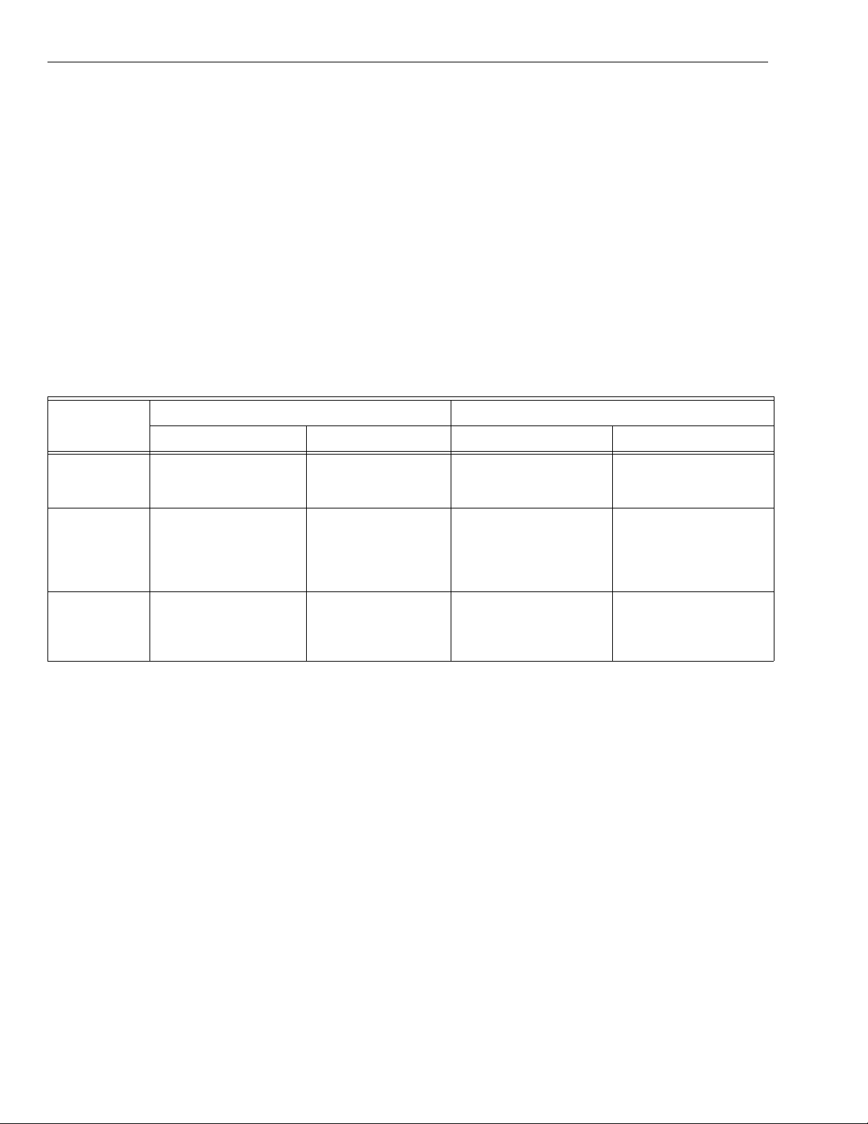
Table 1. Recommended Thermostats.
Trol-A-Temp Logo Honeywell Logo
System
Manual
Changeover
Auto
Changeover
Mechanical Programmable Non-Programmable Programmable
T87F3715/Q539A1436
T87F3707/Q539A1428
T8131C1020 T87F1859/Q539A1014
T8601D2027 Y594D1347 T8600D2069
Thermostats (See Table 1):
Conventional four-wire (R,W,Y,G) thermostats.
Manual or automatic changeover switching subbase for
each zone thermostat.
MABS EZ second-stage timer and emergency heat switch
replace multi-stage or heat pump thermostat.
MABS EZ with heat pump thermostat controls Emergency
Heat mode from thermostat and MABS EZ panel switch.
• Requires separate W1 and Y1 outputs for the heat
and cool calls.
• Requires L terminal energized when Emergency
Heat switch is on.
• W2 thermostat terminal is not used.
• MABS EZ panel timer turns on auxiliary heat when
not in Emergency Heat mode.
Q87F4010/Q539A4026
T8400R
T8000C1002
T8000C1010
T8600D2028
T8601D2019
T8602D2018
T8602D2000
Heat Pump T8011R1006
T8011R1014
T8411R1002
T8411R1028
ORDERING INFORMATION
When purchasing replacement and modernization products from your TRADELINE® wholesaler or distributor, refer to the
TRADELINE® Catalog or price sheets for complete ordering number.
If you have additional questions, need further information, or would like to comment on our products or services, please write or
phone:
1. Your local Home and Building Control Sales Office (check white pages of your phone directory).
2. Home and Building Control Customer Relations
Honeywell, 1885 Douglas Drive North
Minneapolis, Minnesota 55422-4386
In Canada—Honeywell Limited/Honeywell Limitée, 35 Dynamic Drive, Scarborough, Ontario M1V4Z9.
International Sales and Service Offices in all principal cities of the world. Manufacturing in Australia, Canada, Finland, France,
Germany, Japan, Mexico, Netherlands, Spain, Taiwan, United Kingdom, U.S.A.
69-1360–2 2
Page 3
MASTERTROL® AUTOMATIC BALANCING SYSTEM™ (MABS®) EZ ZONE (EZ-2 AND EZ-4) CONTROL PANELS
Dampers: See Fig. 3-7 for hookup drawings. See Table 2 for
recommended dampers.
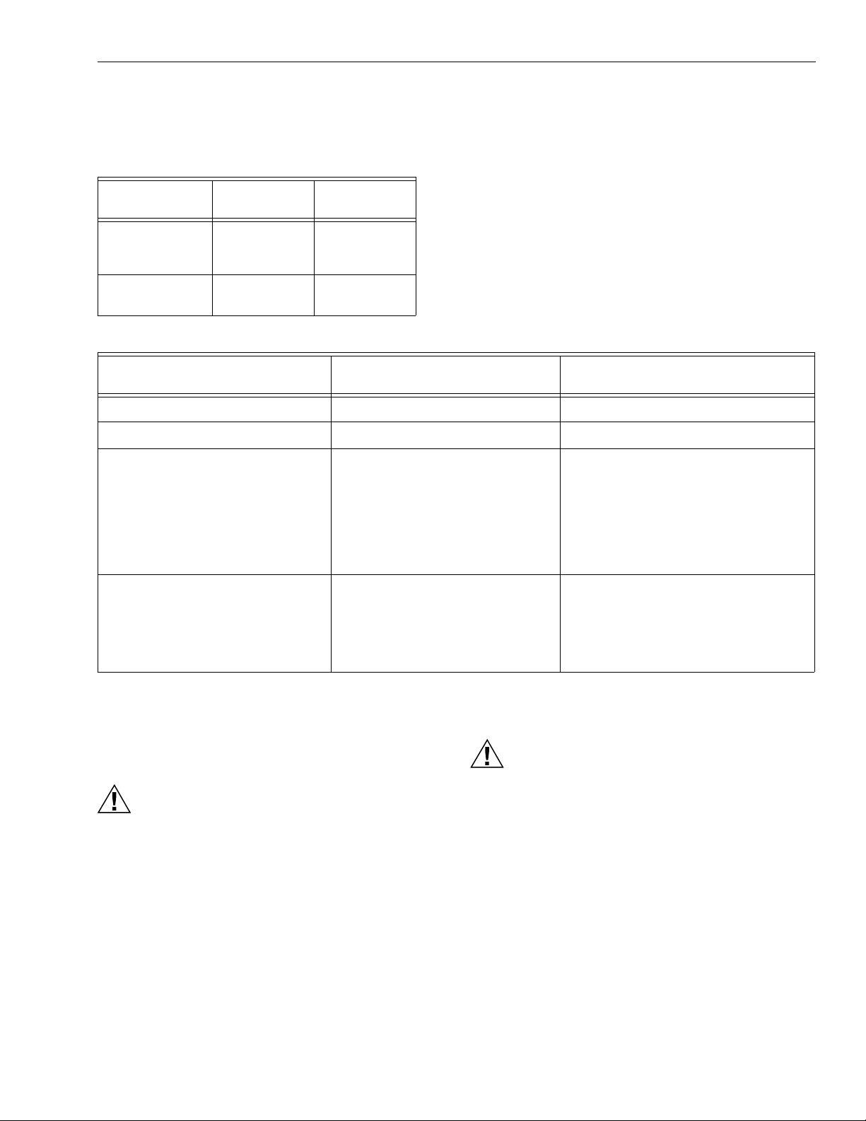
Table 2. Recommended Dampers.
Honeywell
Damper Types Round Rectangular
Power-open/
power-closed
Spring-open/
power-closed
40 VA Transformer AT140D1046 (PMT-40) _
Capacity Protector ZMS/C7735 _
Round Static Pressure Regulator
Damper (SPRD)
MARD AOBD
AOBD-BM
CDO-51
ARD ZDB
ZDS
Table 3. Required Accessories (Not Supplied With Panel).
Accessory Description
7 SPRD
8 SPRD
9 SPRD
10 SPRD
12 SPRD
14 SPRD
16 SPRD
18 SPRD
Accessories:
For required accessories, see Table 3.
Bypass Rated Capacity
(cfm)
300
400
600
750
1200
1800
2400
3200
Rectangular Static Pressure Regulator
Damper (SPRD)
12 x 8 SPRD
12 x 10 SPRD
12 x 12 SPRD
20 x 8 SPRD
20 x 10 SPRD
20 x 12 SPRD
INSTALLATION
Mounting
CAUTION
Equipment Damage Hazard.
Do not mount MABS EZ inside HVAC equipment.
Mount only on wall or on cold air return
1. Mount the thermostats in each zone of the living space
using the installation instructions provided with each
thermostat.
2. Mount the dampers in the ductwork using the installation instructions provided with each damper.
3. Mount the MABS EZ Zone Panel near the HVAC equipment; locate it on a wall or on the cold-air return.
4. Level the MABS EZ for appearance only.
1000
1200
1400
1600
2000
3000
Wiring
CAUTION
Vol tage H a zard.
Can cause electrical shock or equipment damage.
Disconnect power before continuing installation.
Wiring must comply with applicable codes, ordinances, and
regulations.
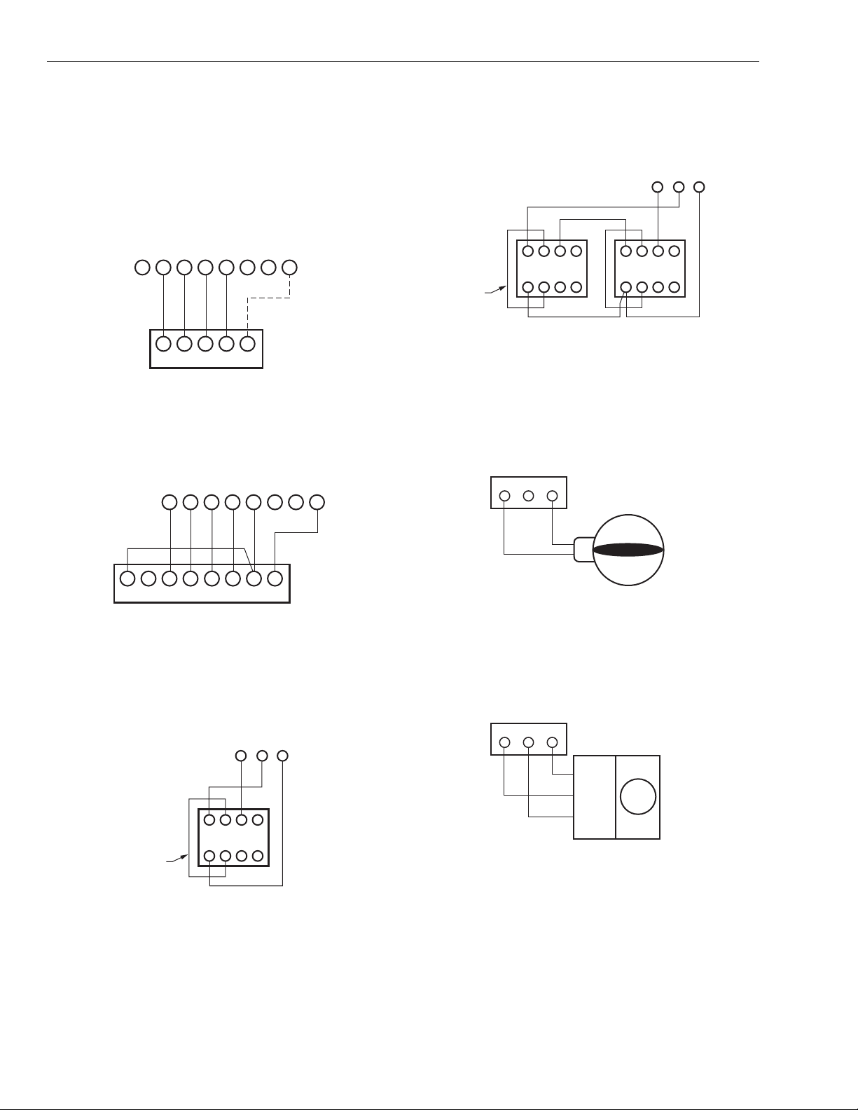
1. Connect thermostats as shown in Fig. 1 and 2.
2. Connect dampers as shown in Fig. 3-7.
3. Connect the ZMS (not supplied) to the TL terminals.The
wires are not polarized. See Fig. 9.
4. Connect the HVAC equipment to the equipment terminals on the left side of the panel. See Figures 10-13.
5. Connect a 40 VA, 24 volt transformer (not supplied) to
TR1 (common) and TR2 (hot). This must be a dedicated
transformer. See Fig. 8.
3 69-1360–2
Page 4
MASTERTROL® AUTOMATIC BALANCING SYSTEM™ (MABS®) EZ ZONE (EZ-2 AND EZ-4) CONTROL PANELS
Wiring Diagrams
See Table 1 for recommended thermostats. See Fig. 1-15 for
wiring appropriate wiring diagrams.
NOTE: The common wire (C to M1) is used only on thermo-
stats that require it.
ZONE CONNECTIONS ON PANEL
THERMOSTAT
L G Y R W M6
GYR WC
ZONE THERMOSTAT
Fig. 1. Typical single-stage thermostat hookup diagram.
ZONE CONNECTIONS ON PANEL
THERMOSTAT
LGYR W M6
MOTOR
M4 M1
M19033
MOTOR
M4 M1
NOTE: Wiring is the same for AOBD, AOBD-BM and IOBD
Dampers.
MOTOR TERMINALS
M6 M4 M1
4
5 6
123
M19036
FIELD
JUMPER
4 5 6
123
DAMPER MOTORS
Fig. 4. AOBD Damper wiring (multiple).
NOTE: For three or more AOBD dampers on one zone, a
Slave Damper Control Relay (SDCR) is required.
DAMPER TERMINALS
ON PANEL
M6 M4 M1
E W2 L G Y1 R W1 C/X
ZONE THERMOSTAT
M19034
Fig. 2. Heat pump thermostats with separate heat and
cool outputs.
Use only thermostats listed in Table 1.
MOTOR TERMINALS
M6 M4 M1
4
5 6
123
FIELD JUMPER
DAMPER MOTOR
M19035
Fig. 3. AOBD damper wiring (single).
POWER CLOSE
SPRING OPEN
C MODEL ARD, ZDS, ZDB
M19037
Fig. 5. ARD or ZD Damper wiring diagram.
NOTE: Multiple dampers can be wired in parallel, with up to
five dampers wired to each panel.
DAMPER TERMINALS
ON PANEL
M6 M4 M1
COM/M1
CL/M6
OP/M4
M19038
Fig. 6. MARD and CDO-51 Damper wiring diagram.
69-1360–2 4
Page 5

MASTERTROL® AUTOMATIC BALANCING SYSTEM™ (MABS®) EZ ZONE (EZ-2 AND EZ-4) CONTROL PANELS
CONTROL PANEL CONNECTIONS
2
1
M6
M4
M1
R8222
24V SPDT RELAY
CW
COM
CCW
ML6161A
MOTOR
M19039
Fig. 7. ML6161 Damper Motor Actuator wiring diagram.
NOTE: The R8222 relay is not required for operation, but if it
is not used, the zone damper LED will be constantly
green.
TR2
TR1
OUTDOOR CONDENSING UNIT
COMPRESSOR RELAY
C
24V TRANSFORMER
FAN RELAY
HEAT RELAY
HVAC CONTROLS
Y
R
G
W
MABS EZ
PANEL
Y2
Y1
O
R
G
B
W1
E
W2
M19042
Fig. 10. Single-stage heating and cooling equipment
wiring diagram.
NOTES:
— Electric Furnace: Set DIP switch 8 to On to ener-
gize the fan with a call for heat.
— Oil Furnace: See Fig. 11 for hookup.
— Hydro-Air: Wired similarly except the zone valve
or circulator relay is connected to the W1. (If the
circulator relay has powered terminals, an isola-
tion relay may be needed. See Fig. 11.) DIP
switch 8 must be set to On to energize the fan
with a call for heat.
24V, 40 VA
TRANSFORMER
MODEL PMT-40
CR
M19040
Fig. 8. Transformer wiring diagram.
NOTE: A dedicated 40 VA, 24 Vac transformer must be
used.
ZMS
SENSOR
or C7735
TL
TL
M19041A
Fig. 9. ZoneMAX or C7735 Sensor wiring diagram.
MABS EZ
PANEL
HVAC CONTROLS
COOLING RELAY
C
24V TRANSFORMER
FAN RELAY
OIL
PRIMARY
T
T
R8222 24V
ISOLATION
RELAY
Y1
R
G
Y2
Y1
O
R
G
B
W1
E
W2
M19043
Fig. 11. Oil furnace and air conditioning wiring diagram.
NOTE: The isolation relay is required to isolate the cooling
transformer from the heating transformer.
5 69-1360–2
Page 6

MASTERTROL® AUTOMATIC BALANCING SYSTEM™ (MABS®) EZ ZONE (EZ-2 AND EZ-4) CONTROL PANELS
HVAC CONTROLS
SECOND STAGE
COOLING RELAY
FIRST STAGE
COOLING RELAY
C
24V TRANSFORMER
FAN RELAY
FIRST STAGE
HEATING RELAY
SECOND STAGE
HEATING RELAY
Y2
Y1
R
G
W1
W2
MABS EZ
PANEL
Y2
Y1
O
R
G
B
W1
E
W2
M19044
Fig. 12. Two-stage heating and cooling wiring diagram.
NOTE: The stage timer energizes the second stage equip-
ment.
C
24V TRANSFORMER
FAN RELAY
FIRST STAGE
HEATING RELAY
SECOND STAGE
HEATING RELAY
HEAT PUMP CONTROLS
IMPORTANT
Y1 must be jumped to W1 for compressor control.
Set DIP switch 8 to On to energize the fan with a call
for heat.
OUTDOOR CONDENSING UNIT
COMPRESSOR RELAY
MABS EZ
COMPRESSOR
RELAY
REVERSING
VALV E
Y
O
R
G
E
W2
PANEL
Y2
Y1
O
R
G
B
W1
E
W2
DIP SWITCH
CONFIGURATION
NO. 8 - ON
2 STAGE
EM. HT.
Fig. 13. Heat pump wiring diagram.
M19045A
NOTES:
— Fossil Fuel Kits with Heat Pumps: The wiring for
these heat pumps is similar but the manufacturer's fossil fuel control must be used. The EZ
equipment terminals are wired using the thermostat terminals shown on the heat pump manufacturer's wiring diagrams.
— Two-speed Compressors: For two-speed com-
pressors or two-speed compressors with auxiliary
heat, the EMM-3U or TotalZone panels are recommended. Call Honeywell Zoning at 800-8288367 for assistance.
69-1360–2 6
Page 7

MASTERTROL® AUTOMATIC BALANCING SYSTEM™ (MABS®) EZ ZONE (EZ-2 AND EZ-4) CONTROL PANELS
OPTIONAL ZoneMAX
OR C7735 SUPPLY AIR
TEMPERATURE
HVAC CONTROLS
SECOND STAGE COOLING RELAY
FIRST STAGE COOLING RELAY
REVERSING VALVE (COOLING)
24V TRANSFORMER (HOT)
REVERSING VALVE (HEATING)
FIRST STAGE HEATING
EMERGENCY HEAT RELAY
SECOND STAGE HEATING RELAY
THIS DIAGRAM SHOWS TYPICAL
SINGLE-STAGE THERMOSTAT
AND DAMPER MOTOR CONNECTIONS.
TM
SENSOR
FAN RELAY
ZoneMAX
FIH
TM
TL
TL
Y2
Y1
O
R
G
B
W1
E
W2
2ND STG. EMG.
HEAT
COOL PURGE FAN EM.HT ZONE 1 ZONE 2
BOOT
YRWM6M4M1
GL
THERMOSTAT MOTOR
ZONE 1
LGYRWM6M4M1
THERMOSTAT MOTOR
ZONE 2
EZ2 REV. F
PURGE
OVERRIDE
GRN - DAMPER OPEN/MOVING
OFF - DAMPER CLOSED
ON
1
2 3 4 5 6 7 8
TR1 TR2
ON
EM HEAT
OFF
ZONE THERMOSTAT
ZONE DAMPERS
Fig. 14. MABS EZ-2 wiring diagram.
GYRW
ZONE 1 THERMOSTAT
4567
123X
OPPOSED BLADE
DAMPERMOTOR
C
GYRWC
ZONE 2 THERMOSTAT
AUTOMATIC ROUND DAMPER
POWERE CLOSED (ARD-PC)
CR
24V, 40 VA
TRANSFORMER
M19046A
7 69-1360–2
Page 8

MASTERTROL® AUTOMATIC BALANCING SYSTEM™ (MABS®) EZ ZONE (EZ-2 AND EZ-4) CONTROL PANELS
OPTIONAL ZoneMAX
OR C7735 SUPPLY AIR
TEMPERATURE
HVAC CONTROLS
SECOND STAGE COOLING RELAY
FIRST STAGE COOLING RELAY
REVERSING VALVE (COOLING)
24V TRANSFORMER (HOT)
REVERSING VALVE (HEATING)
FIRST STAGE HEATING
EMERGENCY HEAT RELAY
SECOND STAGE HEATING RELAY
THIS DIAGRAM SHOWS TYPICAL
SINGLE-STAGE THERMOSTAT
AND DAMPER MOTOR CONNECTIONS.
TM
SENSOR
FAN RELAY
HEAT
TM
ZoneMAX
TL
TL
Y2
Y1
O
R
G
B
W1
E
W2
2ND STG. EMG.
YRWM6M4M1
GL
THERMOSTAT MOTOR
ZONE 1
COOL PURGE FAN EM.HT ZONE 1 ZONE 2 ZONE 3 ZONE 4
GRN - DAMPER OPEN/MOVING
OFF - DAMPER CLOSED
THERMOSTAT MOTOR
ZONE 2
LGYRWM6M4
THERMOSTAT MOTOR
ZONE 2
BOOT
M1
GL
THERMOSTAT MOTOR
ON
1
2 3 4 5 6 7 8
PURGE
OVERRIDE
YRWM6M4M1 LGYRWM6M4
ZONE 1
TR2
TR1
EM HEAT
ON
OFF
M1
ZONE THERMOSTAT
ZONE DAMPERS
GYRW
ZONE 1 THERMOSTAT
4567
123X
OPPOSED BLADE
DAMPERMOTOR
C
GYRWC
ZONE 2 THERMOSTAT
AUTOMATIC ROUND DAMPER
POWERE CLOSED (ARD)
Fig. 15. MABS EZ-4 wiring diagram.
STARTUP AND CHECKOUT
After the installation is complete, verify the operation:
1. Put the Em Heat switch in the off (down) position.
2. Be sure the DIP switches are set correctly. See
Sequence of Operation and Table 6 for correct configuration. The default position is in the off (down) position.
3. Power up the MABS EZ and set the thermostats so no
zones are calling. Verify that the board? enters the
Purge mode.
NOTE: During the two- or three and one-half- minute Purge,
the Purge LED should be amber. During this mode,
the dampers are open and the damper LEDs are
lighted green.
C
GYRW
ZONE 3 THERMOSTAT
4567
123X
OPPOSED BLADE
DAMPERMOTOR
GYRWC
ZONE 4 THERMOSTAT
AUTOMATIC ROUND DAMPER
POWERE CLOSED (ARD)
CR
24V, 40 VA
TRANSFORMER
M19047A
4. Set the zone one thermostat to heat and raise the setpoint to call for heat. The Heat LED is red and the zone
one damper remains green while the other damper
LEDs turn off.
5. Lower the setpoint in zone one and raise the setpoint in
zone two to call for heat. Verify that zone one LED turns
off (also zones three and four turn off when used on
MABS EZ-4) and zone two damper is green.
6. When using a MABS EZ-4, repeat for zones three and
four and verify correct operation.
7. Alternately, the setpoint can be lowered to call for cooling. Then the green cool LED lights.
69-1360–2 8
Page 9

MASTERTROL® AUTOMATIC BALANCING SYSTEM™ (MABS®) EZ ZONE (EZ-2 AND EZ-4) CONTROL PANELS
OPERATION
Sequence of Operation
On a call for heating or cooling, the zone damper to the calling
zone stays open, and the dampers close to the zones that are
not calling. The MABS EZ panel brings on the heating or
cooling and conditioned air is delivered to the calling zone
until the zone is satisfied. When the call is satisfied, the
system enters the Purge mode. This holds open the damper
of the last zone calling and purges into that zone. The Purge
time can be set to three and one-half or two minutes.
Individual Zone Fan Control
When all zones are satisfied, each zone thermostat Fan
switch controls the fan operation for each zone. When
circulation is desired, place the Fan switch in the On position.
The fan runs and closes the dampers to the zones where the
Fan switch is set to Auto.
Multi-Stage Operation
MABS-EZ can control up to two stages of heating and cooling
using singe-stage thermostats. The panel uses a timer to
control the second stage and is adjustable from five minutes
to 30 minutes using DIP switches 5, 6, and 7. See Table 4.
When a call for heating or cooling is not satisfied within the
time set on the stage time, the panel energizes the second
stage of heat or cool and both stages remain on until the call
is satisfied.
Table 4. Stage timer configuration.
Minutes DIP Switch 5 DIP Switch 6 DIP Switch 7
5 Off Off Off
8On Off Off
10 Off On Off
Table 4. Stage timer configuration.
Minutes DIP Switch 5 DIP Switch 6 DIP Switch 7
12 On On Off
15 Off Off On
20 On Off On
25 Off On On
30 On On On
Changeover Operation
The MABS EZ panel uses a standard heating and cooling
thermostat for each zone to allow any zone to call for heating
or cooling. When opposite calls are made from different
zones, MABS EZ accepts the first call. Once the first call is
satisfied, or a maximum of 20 minutes elapses from the start
of an opposite call, MABS EZ allows the opposite call.
Automatic changeover thermostats can also be used to
provide automatic zone changeover.
When opposite calls occur, the panel ensures that both calls
are acknowledged. If the first call is not satisfied within 20
minutes, the panel drops the existing call and goes into the
Purge mode. After completion of the Purge, the panel
switches to the opposite mode until it is satisfied or until 20
minutes elapses.Then it goes back into the Purge mode and
back to the original call. The system continues to switch back
and forth until both calls are satisfied.
Purge Mode
At the end of every call for heat or cool, the panel enters a
Purge mode that holds the last zone damper open for three
and one-half or two minutes. During this time, the panel or
HVAC equipment can operate the fan. Purge is a time delay
that prevents short cycling of the heating and cooling
equipment after each call. The Purge LED lights when the
system is in Purge mode. Press Purge Override button when
the purge LED is lighted to override Purge.
9 69-1360–2
Page 10

MASTERTROL® AUTOMATIC BALANCING SYSTEM™ (MABS®) EZ ZONE (EZ-2 AND EZ-4) CONTROL PANELS
ZoneMAX Sensor Leaving Air Temperature Sensor
Table 5. Purge DIP switch settings.
DIP Switch No. Setting Action
1 Off 3.5 minutes
1 On 2 minutes
2 Off Panel control of
2OnHVAC control of
fan in Purge
fan in Purge
LED Indicators
The panel features several LED status indicators visible
through a window in the cover. See Table 6.
Table 6. LED Status Indicators.
Status
LED Color
Heat Red Heat call Not in heat
Lighted
Not
Lighted Flashing
ZMS high
call
temperature limit
tripped
The ZMS (not included) is a duct-mounted temperature probe
that monitors the supply of air temperature to control capacity
and prevent over-heating or coil icing. The sensor attaches to
the TL terminals at the upper left corner of the panel. See Fig.
9.
IMPORTANT
The ZMS wires must be at least 12 in. away from line
voltage wiring to ensure correct operation. When not
possible, shielded cable must be used.
ZoneMAX Sensor Configuration
DIP switches 2 and 3 set the ZoneMAX Sensor temperature
limit. See Table 7. The recommended setting for fossil fuel/
heat pump systems is 160°F (71°C). For heat pump systems,
the recommended setting is 120°F (49°). The cooling
temperature limit can be set to 40°F (4°C) or 48°F (9°C).
Table 7. ZoneMAX Sensor Configuration.
DIP Switch
No.
2 ZMS 160°F (71°C)
3 ZMS 40°F (4°C)
Off (Default) On
heating limit
cooling limit
Setting
ZMS 120°F (49°C)
heating limit
ZMS 48°F (9°C)
cooling limit
Cool Green Cool call Not in cool
Purge Amber Purge
Fan Green Fan only
Em
Heat
Zone
1,2,
3,4
Red Emergency
Green Damper
mode
call
heat switch
on or thermostat in
emergency
heat
open or
moving
call
Not in
Purge
mode
No fan only
calls
Not in
emergency
heat mode
Damper
closed
ZMS low
temperature limit
tripped
_
_
_
_
Re-Booting the Microprocessor
When conditions hang up the microprocessor, press and
release the Boot button to re-boot the system and enter the
Purge mode.
OPERATION
If the system trips due to exceeding a high or low temperature,
the heating or cooling system shuts down and the fan
continues running to dissipate the conditioned air from the
plenum. If the low limit was tripped, the cool LED flashes
continuously until it resets. If the high limit was tripped, the
Heat LED flashes continuously until it resets.
The ZoneMAX Sensor resets and allows normal system
operation when the supply air temperature rises ten degrees
in cooling mode, or falls ten degrees in heating mode. The ten
degrees provide adequate time to prevent short cycling of the
unit.
Circuit Breaker Protection
A built-in thermal circuit breaker protects the panel against
shorts in the thermostat and damper wiring and the remote
occupied/unoccupied switch. It does not protect against shorts
in the HVAC equipment wiring into the panel.
OPERATION
None of the LEDs light when the circuit breaker tripped. The
fuse is a yellow square or rectangular disk located right of the
TR1 and TR2 terminals. If it is hot to touch, remove panel
power for ten seconds to allow the circuit breaker to cool off
and reset.
69-1360–2 10
Page 11

MASTERTROL® AUTOMATIC BALANCING SYSTEM™ (MABS®) EZ ZONE (EZ-2 AND EZ-4) CONTROL PANELS
Thermostats
The panel can use almost any four-wire (R,W,Y,G) thermostat.
Each zone requires its own switching subbase with either
manual or automatic changeover. See Table 1 for
recommended thermostats.
HEAT PUMP OR MULTI-STAGE THERMOSTATS
Heat pump or multi-stage thermostats are not required for the
MABS EZ panels because a timer in the panel brings on the
second stage. A heat pump thermostat is used only when
emergency heat control from the thermostat is desired. Use
only Table 1 recommended heat pump thermostats.
EMERGENCY HEAT MODE
An emergency heat switch is located on the side of the panel
and can be accessed without removing the cover. A heat
pump thermostat is used only when emergency heat control is
desired from the thermostat instead of from the panel.
Energizing the L terminal on the zone thermostat or switching
the Emergency Heat switch to the On position places the
system in Emergency Heat mode. This switch does not initiate
a call for emergency heat and prevents the first stage (heat
pump) from being used on a call for heat.
Fan On In Heat
The system fan can be set to come on with a heat call, as
required, with a hydro-air, heat pump, or electric heat system.
Set DIP switch 8 to the On position to activate this mode.
Otherwise, leave it in the default Off position.
Second Stage Emergency Heat Jumper
A jumper is installed on the jumper block to energize W2
output during a call for emergency heat. If there are two forms
of auxiliary heat, one can be connected to W2 as the second
stage of heat and the other to E as the emergency heat stage.
See Fig. 4.
Table 8. DIP Switch Settings.
Switch Function
DIP Switch
NO.
1 3.5 minute Purge
2 ZMS 160°F (71°C)
3 ZMS 40°F (4°C)
4 Normal operation Test mode;
5 See Table 4. _.
6 See Table 4. _
7 See Table 4. _
with DIP Switch
Off (Default)
with fan on
heating limit
cooling limit
Switch Function
with DIP Switch
On
2 minute Purge
with fan off
ZMS 120°F (49°C)
heating limit
ZMS 48°F (9°C)
cooling limit
accelerated
timings
8HVAC unit-
controlled fan
Fan on with call for
Heat
11 69-1360–2
Page 12

Printed in U.S.A. on recycled
paper containing at least 10%
post-consumer paper fibers.
MASTERTROL® AUTOMATIC BALANCING SYSTEM™ (MABS®) EZ ZONE (EZ-2 AND EZ-4) CONTROL PANELS
TROUBLESHOOTING
The primary diagnostic tools are the system and damper status LEDs. See Table 9 for troubleshooting guide.
Table 9. Troubleshooting Guide.
Symptom Problem Solution
No LEDs light No power to the panel. • Check for 24 Vac across TR2.
• Check circuit breaker; if hot, a short exists in
thermostat or damper wiring.
Erratic operation Insufficient voltage.
Incorrect configuration
Check for 24 Vac ±10% across TR1 and TR2.
Verify jumpers and DIP switch setting for correct
configuration.
Heat or Cool LEd flashes
Panel in Emergency Heat mode
Panel needs resetting.
Heat LED flashing.
Check position of Em Heat switch.
Press Boot button and recheck system operation.
ZoneMAX Sensor tripped on high limit.
continuously
Heat pump works in
Cool LED flashing.
Incorrect thermostat.
ZoneMAX Sensor tripped on high limit.
Install the correct thermostat.
Heat but not in Cool or in
Cool but not in Heat
Incorrectly wired.
If equipment is heat pump, be sure there is a Y1 or
W1 jumper installed.
Emergency heat not
Incorrectly wired.
Verify thermostat and equipment wiring.
coming on
Incorrect thermostat.
Verify correct thermostat is used.
+RPHDQG%XLOGLQJ&RQWURO +RPHDQG%XLOGLQJ&RQWURO
+RQH\ZHOO +RQH\ZHOO/LPLWHG+RQH\ZHOO/LPLWpH
'RXJODV'ULYH1RUWK '\QDPLF'ULYH
*ROGHQ9DOOH\01 6FDUERURXJK2QWDULR
69-1360–2 G.H. Rev. 9-01 www.honeywell.com/yourhome
09=
 Loading...