

Page 1
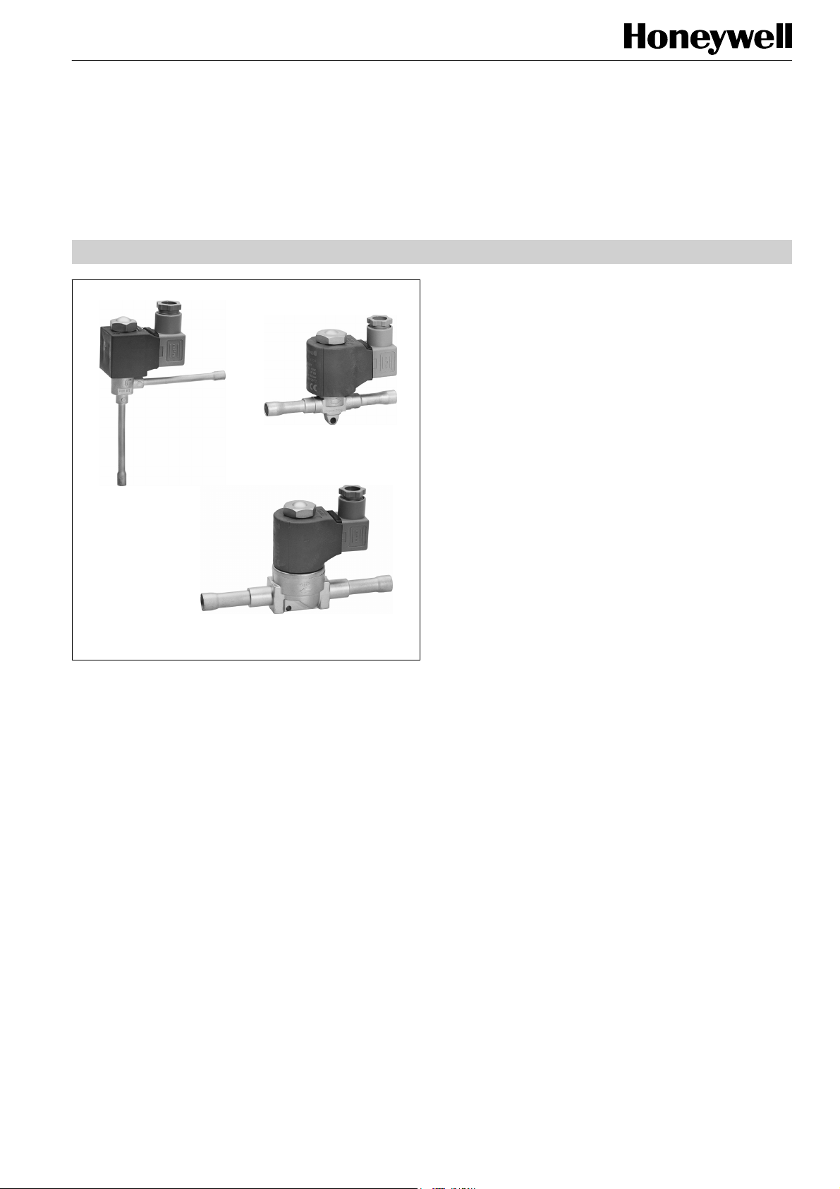
MA
MD
MS
Application
Solenoid valves series M are used in general refrigeration
and for original equipment to cut off/activate the refrigerant
flow in a refrigerating plant.
The solenoid valves can be installed in the liquid line, hot gas
line and suction line of a refrigerating unit.
Materials
Body
Seal material
Connection tubes
Coil
brass, stainless steel
PTFE
solder: copper
flare: brass
copper, steel, Crastin
Series M
SOLENOID VALVES
NORMALLY CLOSED
PRODUCT DATA
Features
• MA: direct operated, angle construction
• MD: direct operated, two way construction
• MS: pilot operated, two way construction
• Normally closed
• Hermetic construction
• Low pressure drop
• High performance
• Direct operated: no minimum pressure differential
required to open the valve
• Pilot operated: minimum pressure differential of
0.05 bar required to open the valve
• Solder and flare connections
• Coils for AC and DC
• Refrigerants: all CFC, HCFC, HFC,
not for ammonia
Specification
Nominal capacity
Maximum pressure PS
Maximum test pressure PF
Min. pressure differential
Max. pressure differential
Max. opening pressure
differential MOPD
Max. medium temperature
Min. medium temperature
Max. ambient temperature
Min. ambient temperature
Number of operating cycles
Standard coil voltages
Voltage tolerance
see tables on page 2
35 bar(a)
50 bar(a)
MA, MD: 0 bar
MS: 0.05 bar
MS: 2 bar
AC-coil: MA, MD: 25 bar
MS: 30 bar
DC-coil: MA, MD: 21bar
MS: 21 bar
125 °C
-45 °C
80 °C
-40 °C
> 1,5 million
AC: 230V, 110V, 24V
DC: 230V, 24V
further voltages on request
AC: ±10%
DC: +10%, -5%
Copyright © 2009 Honeywell GmbH • Subject to change without notice EN0H-1917GE23 R0709
Page 2

SERIES M
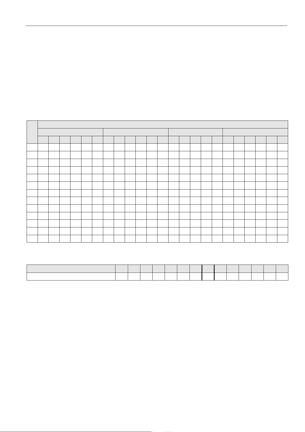
Nominal Capacity QN (kW)
Type
MA 062 0.17 5.21 5.62 5.39 3.87 1.14 1.47 1.45 1.29 - - - -
MD 062 0.17 5.21 5.62 5.39 3.87 1.14 1.47 1.45 1.29 - - - -
MD 102 0.22 6.74 7.27 6.98 5.01 1.48 1.90 1.88 1.67 - - - -
MD 103 0.23 7.05 7.61 7.29 5.24 1.54 1.99 1.96 1.75 - - - -
MS 103 0.9 27.6 29.8 28.5 20.5 6.04 7.78 7.67 6.83 1.54 2.06 1.92 1.80
MS 104 0.9 27.6 29.8 28.5 20.5 6.04 7.78 7.67 6,83 1.54 2.06 1.92 1.80
MS 124 1.6 49.0 52.9 50.7 36.4 10.7 13.8 13.6 12.1 2.74 3.66 3.42 3.19
MS 125 1.6 49.0 52.9 50.7 36.4 10.7 13.8 13.6 12.1 2.74 3.66 3.42 3.19
MS 165 2 61.3 66.1 63.4 45.5 13.4 17.3 17.1 15.2 3.42 4.57 4.27 3.99
MS 167 2 61.3 66.1 63.4 45.5 13.4 17.3 17.1 15.2 3.42 4.57 4.27 3.99
MS 227 4 123 132 127 91.1 26.8 34.6 34.1 30.4 6.85 9.14 8.54 7.98
The nominal capacity QN is based on the following conditions
Medium
Liquid -10 25 1 - 0.4
Hot gas -10 25 1 25 °C 1
Suction gas -10 25 1 - 0.15
Valve selection for other operating conditions see the following tables or consult the Honeywell software
kv-value
(m3/h)
Evaporating
temperature
R134a R22 R407C
t0 (°C) tc (°C)
Liquid Hot gas Suction gas
R404A
R507A
Direct operated
Pilot operated
Condensing
temperature
R134a R22 R407C
Subcooling
Δtc2u (K)
R404A
R507A
temperature
R134a R22 R407C
Hot gas
tH (°C)
Pressure loss
across valve
Δp (bar)
R404A
R507A
EN0H-1917GE23 R0709 2 Honeywell GmbH • Subject to change without notice
Page 3
SERIES M
Valve size calculation for the liquid line
Refrigeration capacity Q0, multiplied with correcting factor fTF,
multiplied with correcting factor f
nominal capacity Q
N.
ΔPF results in the required
QN = Q0 x fTF x fΔPF
QN nominal capacity (according to table on page 2)
Q
0 refrigeration capacity
TF correcting factor for evaporating and liquid
f
temperature
f
ΔPF correcting factor for pressure loss across the valve
Correcting factor fTF for the change of capacity according to the operating temperatures
tL*
(°C)
+10 ±0 -10 -20 -30 -40 +10 ±0 -10 -20 -30 -40 +10 ±0 -10 -20 -30 +10 ±0 -10 -20 -30 -40
0 - - 0.80 0.83 0.85 0.88 - - 0.82 0.83 0.85 0.88 - - 0.80 0.80 0.80 - - 0.73 0.76 0.79 0.83
+5 - - 0.83 0.86 0.89 0.93 - - 0.85 0.87 0.89 0.91 - 0.80 0.80 0.80 0.90 - - 0.77 0.8 0.84 0.88
+10 - 0.84 0.87 0.91 0.94 0.97 - 0.86 0.88 0.90 0.92 0.95 - 0.80 0.90 0.90 0.90 - 0.79 0.82 0.85 0.89 0.94
+15 - 0.88 0.91 0.94 0.98 1.02 - 0.90 0.92 0.94 0.96 0.99 0.90 0.90 0.90 0.90 1.00 - 0.84 0.87 0.91 0.95 1.00
+20 0.89 0.92 0.95 0.99 1.03 1.08 0.92 0.94 0.96 0.98 1.00 1.03 0.90 0.90 0.90 1.00 1.00 0.86 0.89 0.93 0.97 1.02 1.08
+25 0.94 0.96 1.00 1.05 1.09 1.14 0.96 0.98 1.00 1.03 1.05 1.09 0.90 1.00 1.00 1.00 1.10 0.92 0.96 1.05 1.05 1.11 1.18
+30 0.99 1.02 1.06 1.12 1.16 1.22 1.01 1.02 1.05 1.08 1.10 1.14 1.00 1.00 1.00 1.10 1.20 0.99 1.03 1.08 1.14 1.21 1.29
+35 1.04 1.08 1.12 1.18 1.24 1.30 1.05 1.07 1.10 1.13 1.16 1.20 1.10 1.10 1.10 1.20 1.20 1.08 1.13 1.19 1.26 1.34 1.44
+40 1.10 1.14 1.19 1.26 1.32 1.39 1.10 1.12 1.15 1.19 1.22 1.26 1.10 1.20 1.20 1.30 1.30 1.18 1.24 1.32 1.40 1.50 1.63
+45 1.18 1.22 1.28 1.35 1.42 1.50 1.17 1.19 1.22 1.26 1.29 1.34 1.20 1.30 1.30 1.40 1.40 1.32 1.39 1.48 1.59 1.72 1.88
+50 1.25 1.24 1.37 1.45 1.53 1.62 1.23 1.26 1.29 1.33 1.37 1.42 1.30 1.40 1.40 1.50 1.60 1.50 1.59 1.7 1.85 2.02 2.23
+55 1.35 1.41 1.48 1.58 1.67 1.78 1.30 1.33 1.37 1.42 1.46 1.52 1.40 1.50 1.60 1.70 1.80 1.74 1.87 2.02 2.22 2.47 2.79
+60 1.46 1.55 1.61 1.73 1.84 1.97 1.38 1.41 1.46 1.51 1.56 1.63 - - - - - - - - - - -
* Temperature of liquid refrigerant at valve inlet.
Correcting factor f
Pressure loss across valve Δp (bar)
Correcting factor fΔPF
R134a R22 R407C R404A, R507A
ΔPF for the change of capacity according to the chosen pressure loss across the valve
Evaporating temperature t0 (°C)
0.05 0.10 0.15 0.20 0.25 0.30 0.35 0.40 0.45 0.50 0.55 0.60 0.65
2.83 2.00 1.63 1.41 1.26 1.15 1.07 1.00 0.94 0.89 0.85 0.82 0.78 0.76
0.70
Honeywell GmbH • Subject to change without notice 3 EN0H-1917GE23 R0709
Page 4

SERIES M
Valve capacity for the hot gas line
Type
MA 062
MD 062
MD 102
MD 103
MS 103
MS 104
MS 124
MS 125
MS 165
MS 167
MS 227
* Capacities are based on evaporating temperature t0 = -10 °C, hot gas temperature tH = +25 °C and 1 K subcooled refrigerant.
Pressure
loss
across
valve
Δp (bar)
0.2 0.54 0.55 0.57 0.58 0.57 0.68 0.70 0.74 0.76 0.78 0.62 0.65 0.68 0.70 0.60 0.60 0.58 0.53
0.5 0.83 0.86 0.89 0.90 0.89 1.06 1.10 1.15 1.19 1.22 0.98 1.02 1.08 1.11 0.93 0.93 0.90 0.83
1.0 1.12 1.17 1.23 1.25 1.24 1.46 1.51 1.60 1.67 1.70 1.39 1.44 1.52 1.57 1.29 1.29 1.26 1.16
1.5 1.31 1.38 1.47 1.50 1.50 1.74 1.81 1.93 2.01 2.06 1.71 1.77 1.87 1.93 1.54 1.55 1.52 1.41
2.0 1.44 1.52 1.64 1.70 1.70 1.94 2.04 2.19 2.29 2.34 1.96 2.04 2.15 2.22 - - - -
0.2 0.69 0.72 0.75 0.75 0.73 0.77 0.91 0.96 0.99 1.00 0.81 0.83 0.88 0.91 0.77 0.77 0.74 0.68
0.5 1.07 1.11 1.15 1.17 1.16 1.37 1.42 1.49 1.55 1.58 1.27 1.32 1.39 1.44 1.20 1.20 1.17 1.07
1.0 1.44 1.51 1.60 1.62 1.61 1.89 1.96 2.08 2.15 2.20 1.80 1.87 1.97 2.04 1.66 1.67 1.63 1.50
1.5 1.69 1.78 1.89 1.94 1.93 2.25 2.34 2.50 2.60 2.66 2.21 2.29 2.41 2.49 1.99 2.00 1.96 1.82
2.0 1.86 1.97 2.12 2.20 2.20 2.52 2.64 2.83 2.97 3.03 2.55 2.64 2.79 2.88 - - - -
0.2 0.72 0.75 0.78 0.78 0.77 0.80 0.95 1.00 1.03 1.05 0.84 0.87 0.92 0.95 0.80 0.80 0.78 0.71
0.5 1.12 1.16 1.21 1.22 1.21 1.43 1.48 1.56 1.62 1.65 1.33 1.38 1.46 1.50 1.26 1.26 1.22 1.12
1.0 1.51 1.58 1.67 1.69 1.68 1.98 2.05 2.17 2.25 2.30 1.88 1.95 2.06 2.13 1.74 1.74 1.70 1.57
1.5 1.77 1.86 1.98 2.03 2.02 2.35 2.45 2.61 2.72 2.78 2.31 2.39 2.52 2.61 2.08 2.09 2.05 1.90
2.0 1.94 2.06 2.22 2.30 2.30 2.64 2.76 2.96 3.10 3.17 2.66 2.76 2.91 3.01 - - - -
0.2 2.83 2.93 3.04 3.06 3.02 4.20 4.33 4.55 4.70 4.79 3.60 3.71 3.90 4.03 3.09 3.09 3.00 2.74
0.5 4.37 4.53 4.73 4.78 4.72 6.55 6.76 7.13 7.38 7.52 5.61 5.79 6.11 6.33 4.89 4.89 4.80 4.37
1.0 5.93 6.19 6.52 6.63 6.57 9.02 9.35 9.91 10.3 10.5 7.73 8.01 8.49 8.83 6.77 6.86 6.69 6.09
1.5 6.93 7.29 7.77 7.95 7.92 10.8 11.2 11.9 12.4 12.7 9.26 9.60 10.2 10.6 8.14 8.14 8.06 7.37
2.0 7.60 8.07 8.66 9.00 9.00 12.1 12.6 13.5 14.2 14.5 10.4 10.8 11.6 12.2 - - - -
0.2 5.04 5.21 5.40 5.44 5.36 6.40 6.60 6.94 7.17 7.30 5.86 6.07 6.41 6.62 5.60 5.60 5.44 4.96
0.5 7.77 8.07 8.40 8.50 8.39 9.97 10.3 10.9 11.2 11.5 9.27 9.6 10.1 10.5 8.76 8.76 8.52 7.80
1.0 10.5 11.0 11.6 11.8 11.7 13.7 14.3 15.1 15.7 16.0 13.1 13.6 14.3 14.8 12.1 12.1 11.8 10.9
1.5 12.3 13.0 13.8 14.1 14.1 16.4 17.1 18.2 19.0 19.4 16.1 16.6 17.6 18.1 14.5 14.6 14.3 13.2
2.0 13.5 14.3 15.5 16.0 16.0 18.4 19.2 20.6 21.6 22.1 18.5 19.2 20.3 20.9 - - - -
0.2 6.29 6.51 6.76 6.80 6.70 8.00 8.25 8.68 8.96 9.12 7.33 7.59 8.01 8.28 7.00 7.00 6.80 6.20
0.5 9.72 10.1 10.5 10.6 10.5 12.5 12.9 13.6 14.1 14.3 11.6 12.0 12.7 13.1 10.9 10.9 10.6 9.70
1.0 13.2 13.7 14.5 14.7 14.6 17.2 17.8 18.9 19.6 20.0 16.4 17.0 17.9 18.5 15.1 15.2 14.8 13.6
1.5 15.4 16.2 17.2 17.7 17.6 20.5 21.3 22.7 23.7 24.2 20.1 20.8 22.0 22.7 18.1 18.2 17.9 16.5
2.0 16.9 17.9 19.3 20.0 20.0 23.0 24.0 25.7 27.0 27.6 23.2 24.0 25.3 26.2 - - - -
0.2 12.6 13.0 13.5 13.6 13.4 16.0 16.5 17.4 17.9 18.2 14.7 15.2 16.0 16.6 14.0 14.0 13.6 12.4
0.5 19.4 20.1 21.0 21.2 21.0 24.9 25.8 27.1 28.1 28.6 23.2 24.0 25.3 26.2 21.9 21.9 21.3 19.5
1.0 26.3 27.5 29.0 29.5 29.2 34.4 35.6 37.8 39.2 40.0 32.8 33.9 35.8 37.0 30.3 30.4 29.7 27.3
1.5 30.8 32.4 34.5 35.3 35.2 41.0 42.6 45.4 47.4 48.4 40.1 41.6 43.9 45.3 36.3 36.5 35.8 33.1
2.0 33.8 35.9 38.7 39.9 40.0 45.9 48.0 51.5 53.9 55.2 46.3 48.0 50.7 52.4 - - - -
+25 +30 +40 +50 +60 +25 +30 +40 +50 +60 +25 +30 +40 +50 +25 +30 +40 +50
R134a R22 R407C R404A, R507A
Condensing temperature tc (°C)
Direct operated
Pilot operated
Capacity (kW)*
If the hot gas temperature is changed by ±10 °C the valve capacity changes (inversely proportional) by ±2,5 %.
With other evaporating temperatures t
t0 (°C) -50 -40 -30 -20 -10 ±0 +10
R134a - 0.85 0.90 0.95 1.00 1.05 1.09
R22 0.88 0.91 0.95 0.97 1.00 1.03 1.05
R407C 0.83 0.88 0.92 0.95 1.00 1.01 1.06
R404A,
R507A
EN0H-1917GE23 R0709 4 Honeywell GmbH • Subject to change without notice
0.75 0.81 0.88 0.13 1.00 1.05 -
0 the capacities above should be multiplied by the following correcting factors:
Page 5

SERIES M
Valve size calculation for the suction line
Refrigeration capacity Q0, multiplied with correcting factor fTS,
multiplied with correcting factor f
nominal capacity Q
N.
ΔPS results in the required
QN = Q0 x fTS x fΔPS
QN nominal capacity (according to table on page 2)
Q
0 refrigeration capacity
TS correcting factor for evaporating and liquid
f
temperature
fΔPS correcting factor for pressure loss across the valve
Correcting factor fTS for the change of capacity according to the operating temperatures
Evaporating
temperature
t0 (°C)
+60 +50 +40 +30 +20
+10 0.98 0.86 0.78 0.71 0.66
±0 1.19 1.05 0.95 0.86 0.79
-10 1.48 1.29 1.16 1.05 0.96
-20 1.88 1.62 1.44 1.31 1.19
-30 2.42 2.08 1.83 1.65 1.59
-40 3.20 2.71 2.37 2.13 1.92
+10 - 1.14 0.82 0.71 0.63
±0 - 1.24 1.01 0.87 0.77
-10 - 1.57 1.26 1.07 0.94
-20 - 2.02 1.60 1.35 1.17
-30 - 2.67 2.07 1.72 1.49
-40 - 3.62 2.74 2.25 1.93
Correcting factor fΔPS for the change of capacity according to the chosen pressure loss across the valve
Pressure loss across valve Δp (bar)
Correcting factor fΔPS
0.05 0.075 0.10 0.15 0.20 0.30 0.40 0.50 0.60
1.73 1.41 1.22 1.00 0.87 0.71 0.61 0.55 0.50
Condensating temperature tc (°C)
For refrigerant R134a, R22, R407C
For refrigerant R404A, R507A
Honeywell GmbH • Subject to change without notice 5 EN0H-1917GE23 R0709
Page 6

SERIES M
Type Code / Order Information
1. Solenoid Valve
M S 16 5 S 230 V AC
Series
Type:
A = direct operated, angle
D = direct operated
S = pilot operated
Valve size
Connection size in 1/8”
() = flare connection
MMS = solder, metric
S = solder, inch
Voltage
() = without coil
2. Solenoid Coil
Type of coil, capacity For Solenoid Valve Voltage, frequency Voltage tolerance
MC 062, 8 W MA 062(S)(MMS)
MC 102-227, 13 W MD 102(S)(MMS)
MC 102-227, 20 W MD 102(S)(MMS)
International protection rating IP65, coil incl. e.l.c.b.-protected plug to DIN 43650 with cable gland; conduit thread PG11.
230 V, 50/60 Hz
MD 062(S)(MMS)
MD 103(S)(MMS)
MS 103-227(S)(MMS)
MD 103(S)(MMS)
MS 103-227(S)(MMS)
110 V, 50/60 Hz
24 V, 50/60 Hz
230 V, 50/60 Hz
110 V, 50/60 Hz
24 V, 50/60 Hz
24 V DC
230 V DC
±10 %
±10 %
+10 %
-5 %
EN0H-1917GE23 R0709 6 Honeywell GmbH • Subject to change without notice
Page 7

Dimensions and Weights
SERIES M
For tube
(E)
MA 062MMS 6 mm ODF 6 mm 88 88 142 47 0.15 0.30
MA 062S 1/4" ODF 1/4" 88 88 142 47 0.15 0.30
MD 062 7/16" UNF 6 mm, 1/4" 65 17 57 47 0.19 0.33
MD 062MMS 6 mm ODF 6 mm 112 17 57 47 0.17 0.31
MD 062S 1/4" ODF 1/4" 112 17 57 47 0.17 0.31
MD 102 7/16" UNF 6 mm, 1/4" 68 19 64 54 0.19 0.33
MD 102MMS 6 mm ODF 6 mm 118 19 64 54 0.17 0.31
MD 102S 1/4" ODF 1/4" 118 19 64 54 0.17 0.31
MD 103 5/8" UNF 10 mm, 3/8" 71 19 64 54 0.28 0.52
MD 103MMS 10 mm ODF 10 mm 118 19 64 54 0.25 0.49
MD 103S 3/8" ODF 3/8" 118 19 64 54 0.25 0.49
MS 103 5/8" UNF 10 mm, 3/8" 84 12 79 54 0.51 0.75
MS 103MMS 10 mm ODF 10 mm 159 12 79 54 0.55 0.79
MS 103S 3/8" ODF 3/8" 159 12 79 54 0.55 0.79
MS 104 MMS 12 mm ODF 12 mm 159 12 79 54 0.56 -
MS 104S 1/2" ODF 1/2" 159 12 79 54 0.56 -
MS 124 3/4" UNF 12 mm, 1/2" 91 12 79 54 0.54 0.77
MS 124MMS 12 mm ODF 12 mm 159 12 79 54 0.56 0.79
MS 124S 1/2" ODF 1/2" 159 12 79 54 0.56 0.79
MS 125S
MS 165 7/8" UNF 16 mm, 5/8" 97 12 79 54 0.57 0.80
MS 165S
MS 167S
MS 227S
16 mm,
5/8" ODF
16 mm,
5/8" ODF
22 mm,
7/8" ODF
22 mm,
7/8" ODF
diameter
Direct operated
Pilot operated
16 mm, 5/8" 159 12 79 54 0.56 -
16 mm, 5/8" 159 12 79 54 0.59 0.82
22 mm, 7/8" 173 12 79 54 0.59 -
22 mm, 7/8" 262 22 88 54 1.45 1.65
Dimensions (mm) Weight (kg) Type Connections
A B C D
without coil
230 V AC
with coil
230 V AC
MD MS MA
Honeywell GmbH • Subject to change without notice 7 EN0H-1917GE23 R0709
Page 8

SERIES M
Installation
• Position of plunger tube should be from upright to
horizontal position.
• Arrow on valve body must correspond with flow direction.
• Keep 45 mm distance clear above the valve for
assembly/disassembly of coil.
• Fit solenoid valve so that it is drip proof.
• Solder valves:
Remove cap nut, coil and gaskets before soldering
Max. temperature of valve body: 125 °C.
When soldering, always point flame away from valve
body
When assembling after soldering, fit the coil’s top and
bottom seal rings.
• Flare valves:
When tightening flare nuts grip at wrench flats on the
valve body provided for this purposes
Do not use coil and plunger tube as lever (thin-walled
plunger tube).
When installing direct operated valves with 20 W DC
coil, the flare nut must be tightened in that way that one
flat of the nut is in parallel with the lower surface of the
coil.
• Voltage of coil and network must correspond.
• The flat spade terminals is the earth connection. The
protective conductor must also be connected at the plant.
• Do not energize the coil before assembling on the valve
body.
• All gaskets must be fitted carefully in order to achieve
protection to IP65.
• Tighten fixing screw of connector.
• Constructive modifications at the valve are not allowed.
Automation and Control Solutions
Honeywell GmbH
Hardhofweg
74821 Mosbach/Germany
Phone: +49 (0)
Fax: +49 (0)
62 61 / 81-475
62 61 / 81-461
E-Mail: cooling.mosbach@honeywell.com
www.honeywell-cooling.com
KAT-MV-002
EN0H-1917GE23 R0709 8 Honeywell GmbH • Subject to change without notice
Manufactured for and on behalf of the
Environment and Combustion Controls
Division of Honeywell Technologies Sàrl,
1180 Rolle, Z. A. La Pièce 16, Switzerland
by its authorized representative Honeywell GmbH
 Loading...