

Page 1
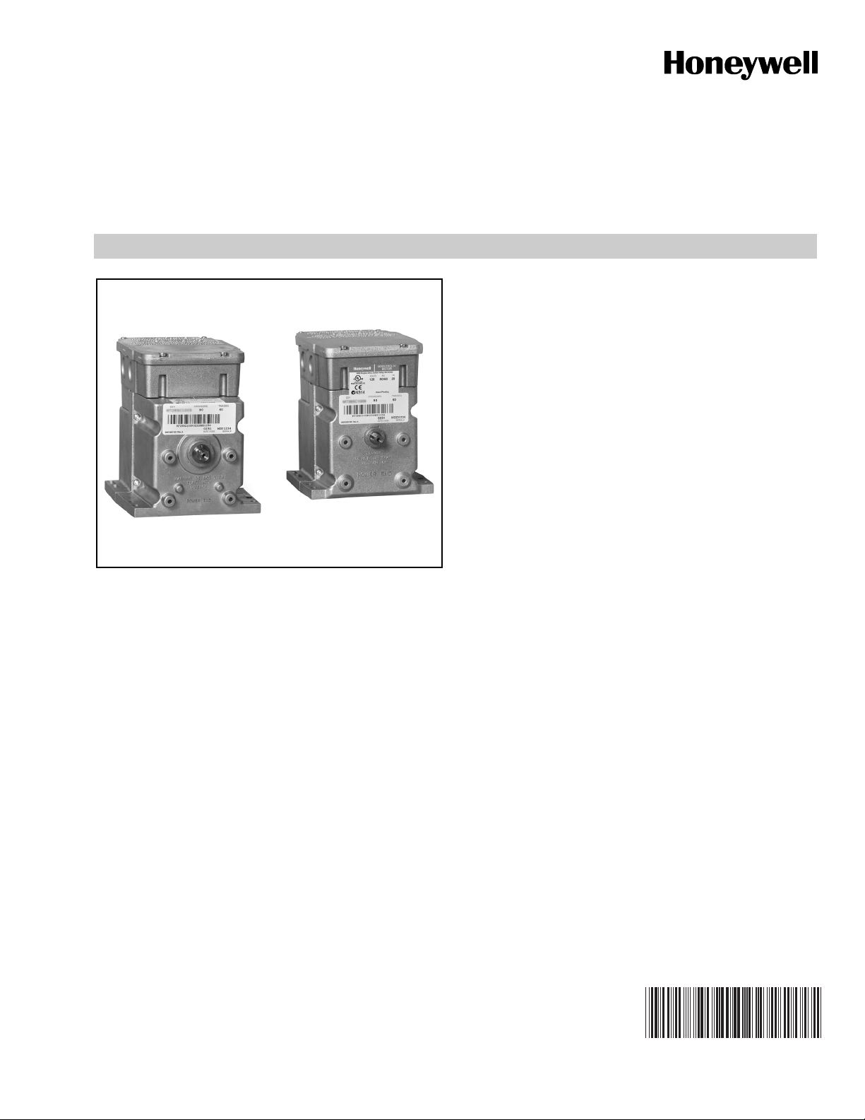
Series 90
Modutrol IV™ Motors
APPLICATION
The Series 90 Modutrol IV™ Motors are spring return and
non-spring return modulating proportional control motors. Use
these motors with controllers that provide a Series 90 output
to operate dampers or valves.
PRODUCT DATA
FEATURES
• Replaces M934A,D, M941, M944A,C,D, M945A,D,F,
M954, M965, and M975 motors.
• Integral junction box provides NEMA 3 weather
protection.
• Integral spring return returns motor to normal position
when power is interrupted.
• Motor and circuitry operate from 24 Vac. Models
available with factory installed transformer, or a field
added internal transformer.
• Quick-connect terminals are standard—screw terminal
adapter is available.
• Adapter bracket for matching shaft height of older
motors is available.
• Motors have field adjustable stroke (90° to 160°).
• Die-cast aluminum housing.
• Integral auxiliary switches are available factory
mounted, or can be field added.
• Nominal timing standard of 30 seconds (90° stroke),
and 60 seconds (160° stroke). Other timings available.
• Spring return motors can operate valve linkages form
power end or auxiliary end shafts for normally closed
or normally open valve applications.
• All models have dual shafts (slotted and tapped on
both ends).
• All models have auxiliary switch cams.
• Fixed torque throughout the entire voltage range.
• Motors are designed for either normally open or
normally closed valves and dampers.
• Field addable interface modules can be mounted in the
junction box to upgrade the motor to Series 70
(electronic) control.
Contents
Application ........................................................................ 1
Features ........................................................................... 1
Specifications ................................................................... 2
Ordering Information ........................................................ 2
Wiring ............................................................................... 7
Settings and Adjustments ................................................. 8
Operation .......................................................................... 9
Checkout .......................................................................... 12
Replacement .................................................................... 12
63-2631-02
Page 2
SERIES 90 MODUTROL IV™ MOTORS
SPECIFICATIONS
TRADELINE Models: Selected and packaged to provide
ease of stocking, ease of handling and maximum replacement value. Specifications are the same as those of standard models unless specified otherwise.
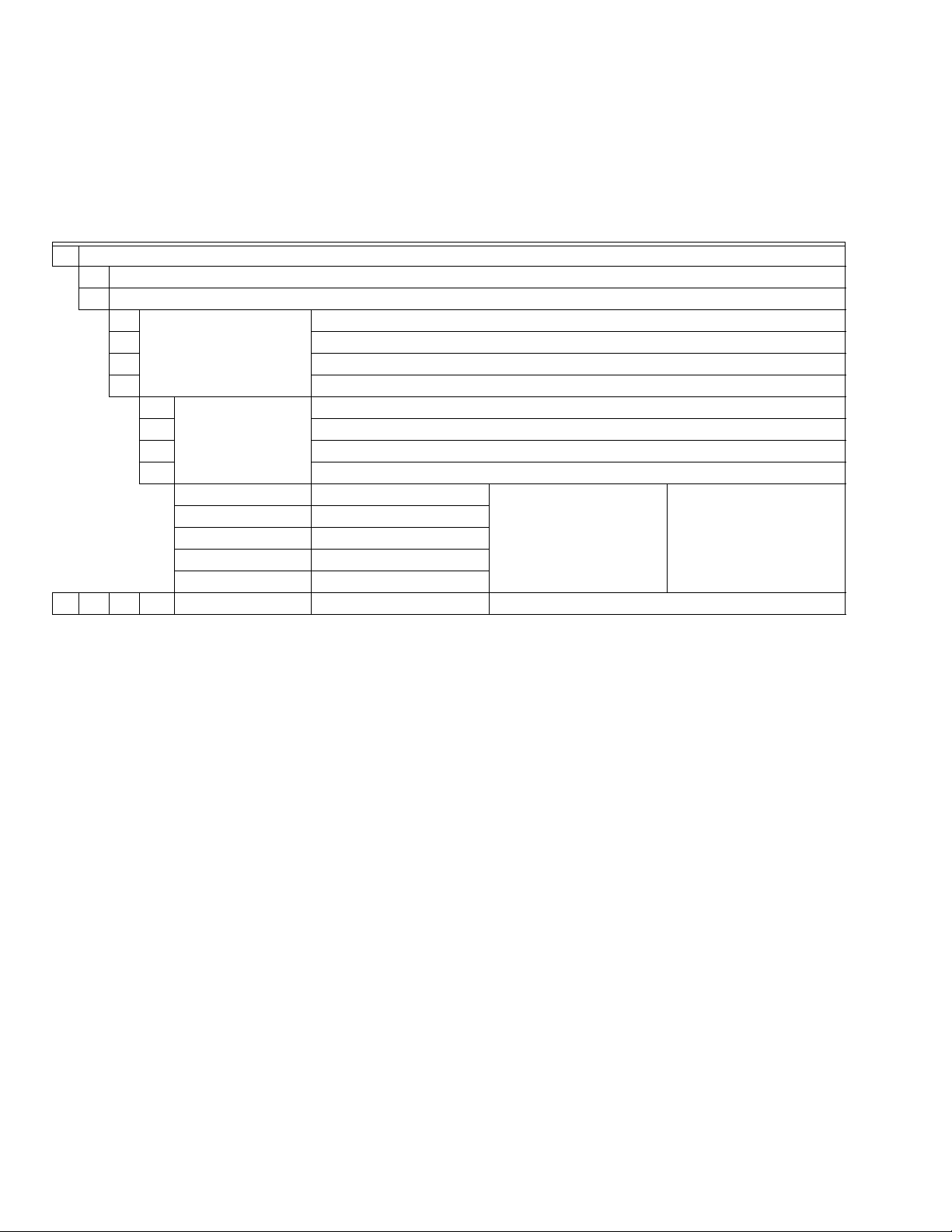
Table 1. Modutrol IV Series 3 Version Order Number Guide.
M Motor
91 Proportioning Series 90 Control
94 Flame Safeguard Firing Rate Motor
6 60 lb-in. Spring Return 35 lb-in. Non-Spring Return
7 75 lb-in. Non-Spring Return
8 150 lb-in. Non-Spring Return
9 300 lb-in. Non-Spring Return
1 Dual-ended shaft Non-Spring Return
2 Normally Closed (NC) Spring Return
4 Non-Spring Return
5 Normally Closed (NC) Spring Return
A 0 Auxiliary Switches Adjustable Stroke Normally Closed
B 1 Auxiliary Switch
C 2 Auxiliary Switches
D 0 Auxiliary Switches
E 1 Auxiliary Switch
M 91 8 4 A XXXX See Catalog for Complete O.S. Number
NOTE: Auxiliary switches can only be added to motors that
include auxiliary switch cams. (These cams cannot
be field-added.)
Modutrol IV Order Number Guide: See Table 1.
NOTE: Torque designation corresponds to torque rating at standard timing (nominally 60 sec for 160° and 30 sec for 90° except
for 300 lb-in. motors which have timings of 2 or 4 min).
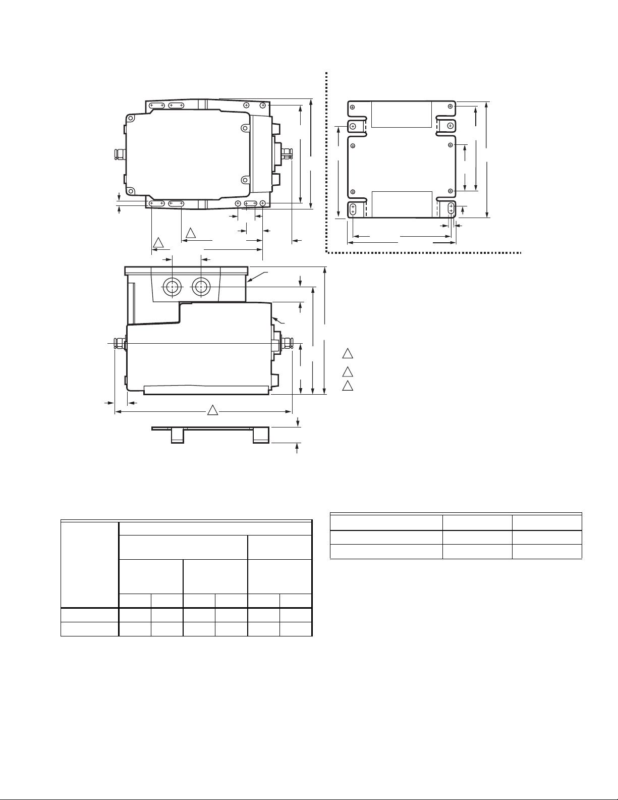
Dimensions: Refer to Fig. 2.
Electrical Ratings: Refer to Table 2.
Control Inputs: Proportional, Series 90.
NOTE: Motor Series 90 control can be either Electronic, or
Mechanical (135 ohm).
Auxiliary Switch Ratings: Refer to Table 3.
Ambient Temperature Ratings:
Maximum: 150° F (66° C) at 25% duty cycle.
Minimum: -40° F (-40° C).
NOTE: 25% duty cycle indicates that the motor operates for
6 out of every 24 hours.
Dead Weight Load On Shaft:
Power or Auxiliary End: 200 lb (90.8 kg) maximum.
Maximum Combined Load: 300 lb (136 kg). (Dual shaft
motors only.)
Crankshaft: 3/8 in. (9.5 mm) square. (Some models have
double-ended shafts.)
Stroke: Models available with field adjustable stroke from 90°
to 160° (See Settings and Adjustments on page 8).
ORDERING INFORMATION
When purchasing replacement and modernization products from your TRADELINE® wholesaler or distributor, refer to the
TRADELINE® Catalog or price sheets for complete ordering number.
If you have additional questions, need further information, or would like to comment on our products or services, please write or
phone:
1. Your local Honeywell Automation and Control Products Sales Office (check white pages of your phone directory).
2. Honeywell Customer Care
1885 Douglas Drive North
Minneapolis, Minnesota 55422-4386
In Canada—Honeywell Limited/Honeywell Limitée, 35 Dynamic Drive, Toronto, Ontario M1V 4Z9.
International Sales and Service Offices in all principal cities of the world. Manufacturing in Australia, Canada, Finland, France,
Germany, Japan, Mexico, Netherlands, Spain, Taiwan, United Kingdom, U.S.A.
63-2631—02 2
Page 3
SERIES 90 MODUTROL IV™ MOTORS
TOP VIEW OF BRACKET TOP VIEW
1/4
(7)
AUXILARY
END
9/16 (15)
3
2
4-1/16 (103)
1-1/2 (37)
4-1/16 (103)
1
13/16
(20)
13/16
(20)
POWER
END
1-1/2 (37)
JUNCTION
BOX
4-7/8
(124)
3/4
(19)
MOTOR
2-9/16
(66)
5-1/2
(140)
5-3/8
(137)
4-5/8
(116)
POWER END
1/4 (7)
4-7/8 (124)
5-9/16 (141)
6-7/16
(164)
SPRING RETURN MODEL SHOWN
FOR HIGH TORQUE (60 LB-IN.) SPRING RETURN MODELS 8-3/4 (222).
1
FOR NON-SPRING RETUIRN MODELS 7-5/16 (185).
2
FOR HIGH TORQUE (60 LB-IN.) SPRING RETURN MODELS (SHOWN).
FOR NON-SPRING RETURN MODELS.
3
2-5/16
(58)
11/16
(17)
4-1/4
(107)
5-13/16
(148)
ADAPTER
BRACKET
Fig. 1. Modutrol IV Motor mounting dimensions in inches (mm).
Table 2. Series 90 Modutrol Motor Power Consumption
Ratings.
Power Consumption
Spring Return
Non-Spring Return Motors
Motors
75, 150 and
Internal
Transformer
300 lb-in.
Tor que
(VA) (W) (VA) (W) (VA) (W)
35 lb-in.
Torqu e
60 lb-in.
Torque
No 14 12 18 16
Yes 16 14 20 18
3/4
(19)
M18998
Table 3. Auxiliary Switch Ratings (in Amps).
Single Contact Rating
a
120 V 240 V
Full Load 7.2 3.6
Locked Rotor 43.2 21.6
a
40 VA pilot duty, 120/240 Vac on opposite contact.
Timing And Torque: Refer to Table 4.
Approvals:
Underwriters Laboratories Inc. Listed: File No. E4436, Guide
No. XAPX.
Canadian Standards Association Certified: General Listed File
No. LR1620, Guide 400-E.
U.S. Patents: pending
3 63-2631—02
Page 4

SERIES 90 MODUTROL IV™ MOTORS
Table 4. Series 90 Modutrol Motor Timing and Torque Ratings.
b
c
Nominal Timing
a
in sec
Rated Torque in lb-in. (N•m)
Normal Running Torque Breakaway Torque
90° 160° Spring Return Non-Spring Return Spring Return Non-Spring Return
30 60 — 35 (4) — 70 (8)
15d/30 30d/60
60 (6.8) 75 (8.5) 120 (13.6) 150 (17)
30 60 — 150 (17) — 300 (34)
60 120 — 300 (34) — 600 (68)
a
Timings apply to all TRADELINE models. Some OEM models are available with non-standard timing/torque.
b
The torque rating for dual-ended shaft motors is the sum of the shaft torques (power-end torque plus auxiliary-end torque).
c
Breakaway torque is maximum torque available to overcome occasional large loads such as a seized damper or valve.
d
Low timing is for M9184D1005 only.
NOTE: Some 150 lb-in. and 300 lb-in. torque adjustable stroke motors have timings that are twice that of the nominal timing.
IMPORTANT
Never use a Modutrol Motor continuously at the
Breakaway Torque rating.
Q181 Auxiliary Potentiometer for sequence or unison control of
1 to 4 additional modulating (Series 90) motors.
Q209E,F Potentiometer limits motor minimum position.
Accessories:
220736 Internal Auxiliary Switch Kit can be field-installed.
One- (220736A) and Two- (220736B) switch kits available.
220738A Adapter Bracket raises motor shaft height by 19 mm
to match that of previous Modutrol Motor models.
220741A Screw Terminal Adapter converts the standard
quick-connect terminals to screw terminals.
221455A Infinitely Adjustable Crank Arm approximately 0.75
inch shorter than the 4074ELY Crank Arm, can rotate
through downward position and clear base of motor without
requiring use of adapter bracket.
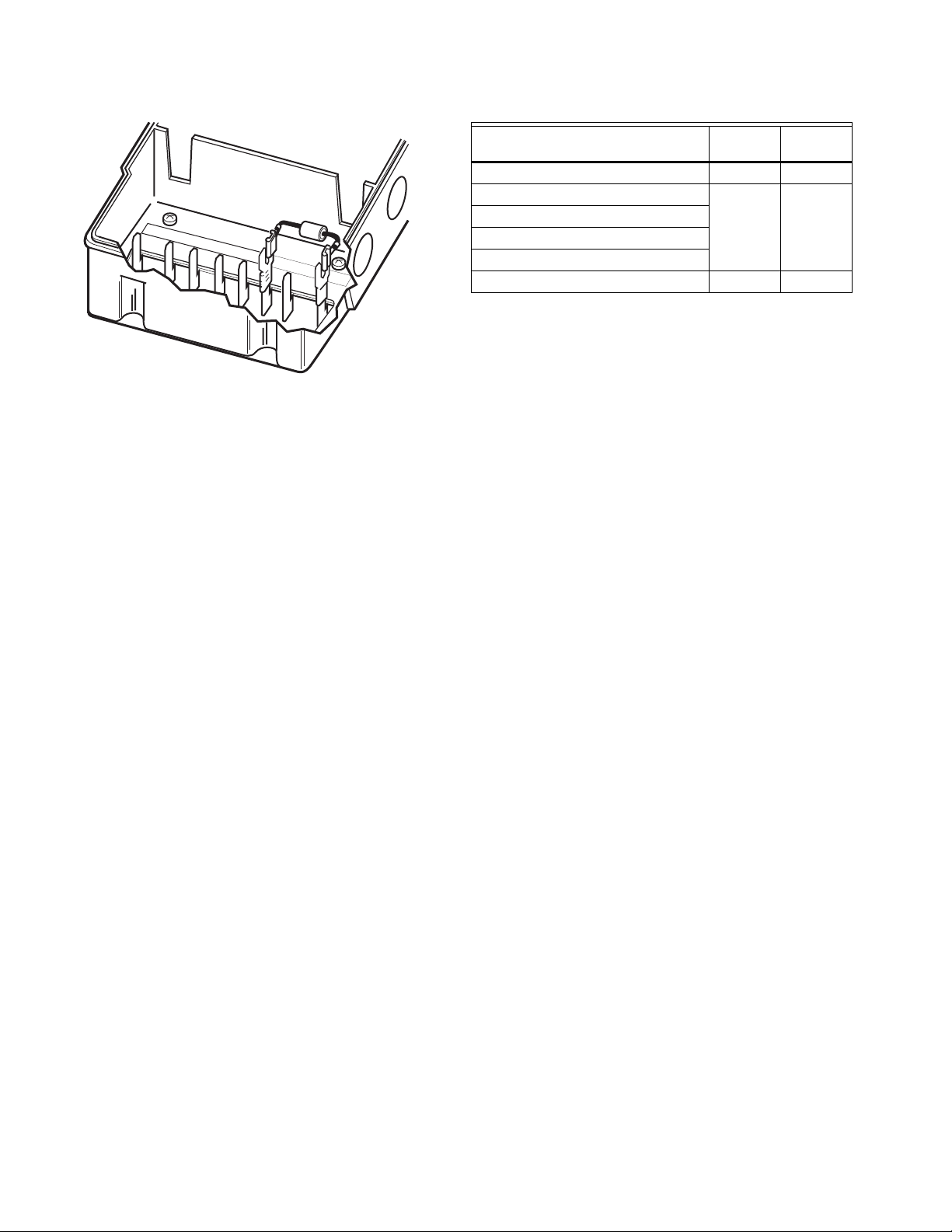
221508A Resistor Board plugs onto Series 90 Motor quick-
connect wire terminals. Provides same functionality as
4074BYK, 4074EAU, 4074EDC, or 4074EED Resistor Kits.
4074BYK Series 90 Resistor Kit provides for unison control of
up to six Series 90 Motors.
4074EAU W973 Resister Kit provides for control of two or
three Series 90 Motors from a W973 Single-zone Logic
Panel or W7100 Discharge Air Controller.
4074EDC 4-20 mA Resistor Kit drives one Series 90 Motor
from a 4-20 mA controller.
4074EED Unison Control 4-20 mA Resistor Kit provides for
control of up to four Series 90 Motors from one 4-20 mA
controller.
Q5001 Bracket and Linkage Assembly connects Modutrol
Motor to a water or steam globe valve.
Q605 Damper Linkage connects motor to damper. Includes
motor crank arm.
Q607 External Auxiliary Switch controls auxiliary equipment as
a function of motor position.
Q7130A Interface Module with selectable voltage ranges
(4-7 Vdc, 6-9 Vdc, and 10.5-13.5 Vdc) adapts motor to
M71XX function.
Q7230A Interface Module with selectable control (2-10 Vdc or
4-20 mA) and adjustable zero and span adapts motor to
M72XX function.
Q7330A Interface Module for W936 Economizer applications
adapts motor to M73XX function.
ES650-117 Explosion-Proof Housing encloses motor for use in
explosive atmospheres. Not for use with Q5001 (or any
other valve linkages). Order separately from EGS Enclosures. To order, contact: EGS Enclosures,
(281) 774-3763; or write to:
EGS Enclosures in Houston, TX
Karen Barfield 281-774-3763
[email protected]
http://appletonelec.com/
part number ES-650-117
4074ERU Weatherproofing Kit provides NEMA 3 rating for
Modutrol IV Motors mounted in position other than upright.
50017460-001 Internal Transformer; 24/120/230 Vac 50/60 Hz
You a 7617DM coupling assembly from Honeywell to use with
the cover.
primary, 24 Vac secondary, quick connect terminals.
50017460-003 Internal Transformer; 120 Vac 50/60 Hz pri-
mary, 24 Vac secondary, quick connect terminals.
7617ADW Crank Arm approximately 0.75 inch shorter than
7616BR Crank Arm. Can rotate through downward position
and clear base of motor without requiring use of adapter
bracket.
Q100 Linkage connects Modutrol Motor to V51 Butterfly Valve.
Requires the 220738A adapter bracket (packed with
TRADELINE Modutrol IV Motors).
M944A,C,D, M954 M9194, M9194
M934D M9164, M9171, M9174
M945A,D,F, M955 M9182, M9185
M941 M9484, M9494
Table 5. Modutrol Motor Cross-Reference.
Original Motor Replacements
63-2631—02 4
Page 5
SERIES 90 MODUTROL IV™ MOTORS
INSTALLATION
When Installing this Product...
1. Read these instructions carefully. Failure to follow them
could damage the product or cause a hazardous condition.
2. Check the ratings given in the instructions and on the
product to make sure the product is suitable for your
application.
3. Installer must be a trained, experienced service technician.
4. After installation is complete, check out product operation as provided in these instructions.
CAUTION
Electrical Shock or Equipment Damage Hazard.
Can shock individuals or short equipment circuitry.
Disconnect all power supplies before installation.
Motors with auxiliary switches can have more than one
disconnect.
CAUTION
Equipment Damage Hazard.
Can damage the motor beyond repair.
Never turn the motor shaft by hand or with a wrench.
Forcibly turning the motor shaft damages the gear train
and stroke limit contacts.
Mounting
CAUTION
Equipment Damage Hazard.
Can damage the motor beyond repair.
Always install motors with the crankshaft horizontal.
Improper motor mounting can result in inadequate
motor gear train lubrication.
Use the following guidelines for proper motor mounting:
• Always install motors with the crankshaft horizontal.
• Mounting flanges extending from motor housing base are
drilled for 1/4 inch (6.4 mm) machine screws or bolts.
• Non-Spring Return Motors are shipped from the factory in
the closed position (at the limit of counterclockwise rotation,
as viewed from the power end of the motor).
• Spring Return Motors are shipped from the factory in their
normal position:
— Normally closed models: shipped at limit of counter-
clockwise rotation, as viewed from the power end of the
motor.
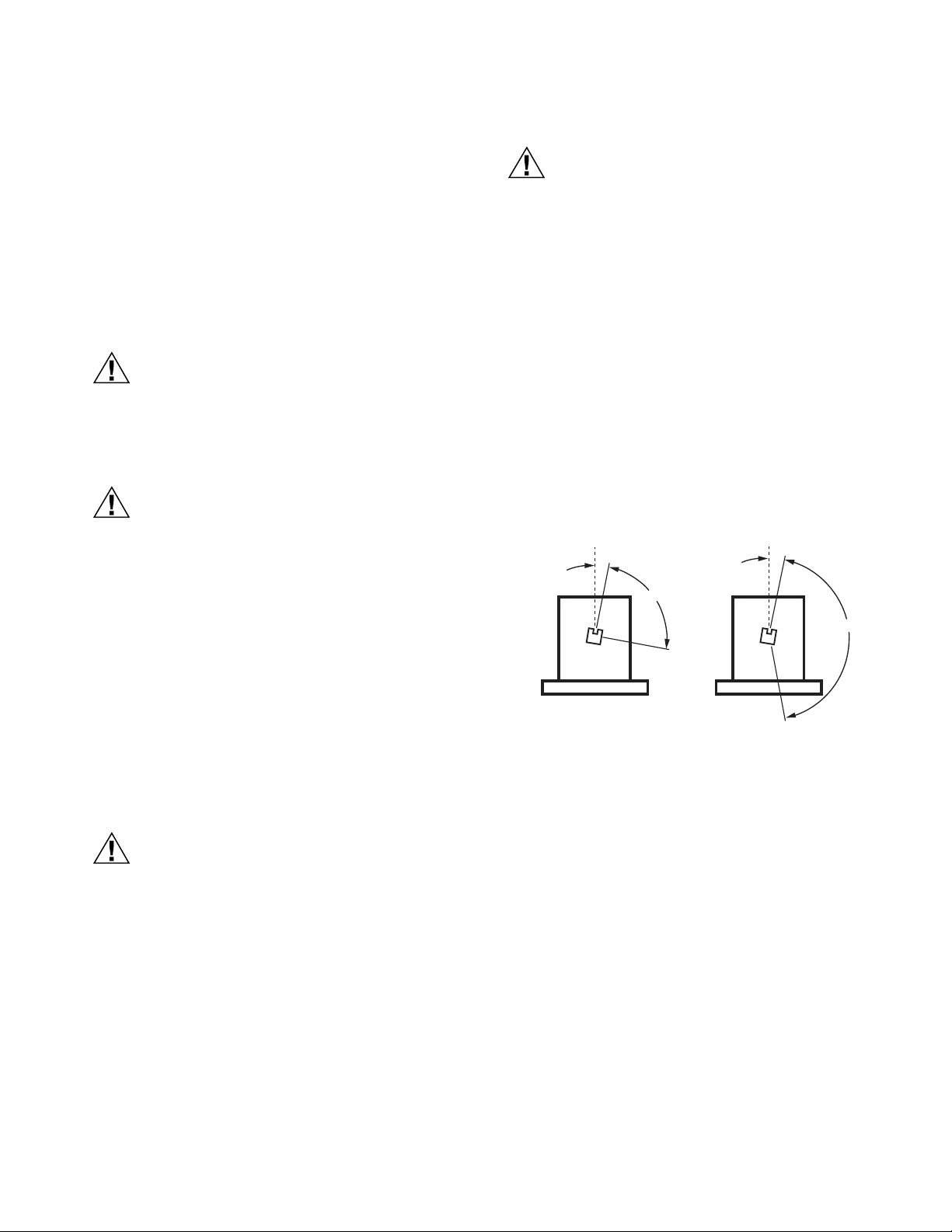
NOTE: See to Fig. 2 for graphical representation of full open
and full closed.
VERTICAL
REFERENCE
10
FULLY
CLOSED
VERTICAL
REFERENCE
10
90
FULLY
CLOSED
IMPORTANT
Always conduct a thorough checkout when installation is complete.
Location
Allow enough clearance for installing accessories and motor
servicing when selecting a location (See Fig. 2). If located
outdoors, use liquid-tight conduit connectors with the junction
box to provide NEMA 3 weather protection. If mounted
outdoors in a position other than upright, install a 4074ERU
Weatherproofing Kit and liquid-tight connectors to provide
NEMA 3 protection.
CAUTION
Motor Damage Hazard.
Deteriorating vapors and acid fumes can damage
metal parts.
Install motor in areas free of acid fumes and other
deteriorating vapors.
In excessive salt environments, mounting base and screws
should be zinc or cadmium plated, not stainless steel or brass.
Use the 220738A Adapter Bracket for mounting on these
surfaces.
160
FULLY
OPEN
FULLY
90 DEGREE STROKE
160 DEGREE STROKE
OPEN
M17712
Fig. 2. Motor Shaft Positions at Stroke Limits
(Viewed from Power End of Motor).
Adapter Bracket
The 220738A Adapter Bracket, positioned between the motor
and the equipment, raises motor shaft height by 0.75 in.
(19 mm) to match that of the former Modutrol Motor.
The following applications require this bracket:
• Q607 External Auxiliary Switch.
• Damper linkage applications require added clearance to
allow:
— crank arm rotation through the downward position.
— sufficient damper linkage to reach the motor shaft.
• All valve linkages except the Q5001.
5 63-2631—02
Page 6
SERIES 90 MODUTROL IV™ MOTORS
STANDARD
BOLTS (4)
1
END
POWER
ADAPTER
BRACKET
EQUIPMENT
BASE
POWER END
BOLTS
PROVIDED (4)
WIRING
BOX
MOTOR
POWER END
1 #12 OR 1/4" ZINC PLATED
MACHINE SCREWS OR BOLTS
NON-SPRING RETURN
SPRING RETURN
M18999
NOTE: When no bracket is used in replacement applications, damper linkages require adjustment for the new shaft position.
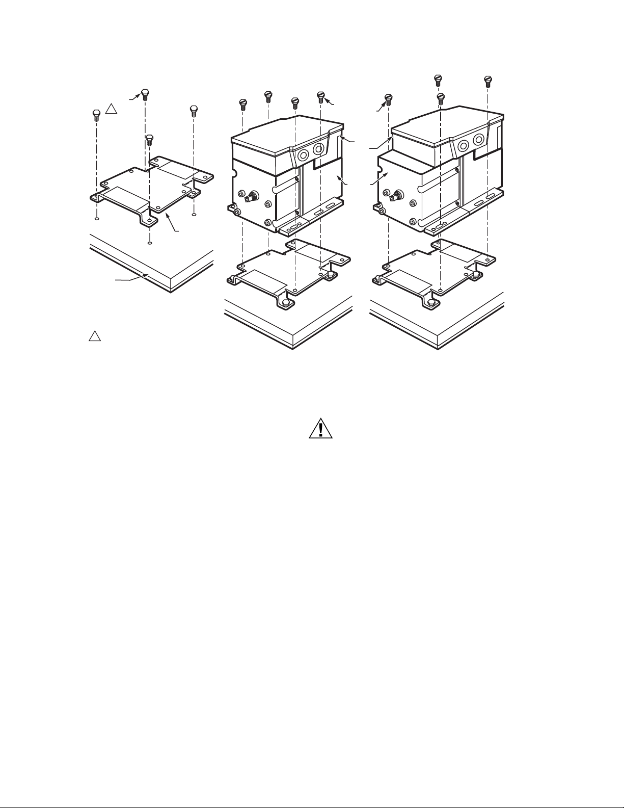
Fig. 3. Mounting the Motor with an Adapter Bracket.
To mount the motor with the bracket (See Fig. 3):
1. Mount the bracket to the equipment with existing or standard bolts.
2. Using the provided bolts, mount the motor to the bracket
threaded holes.
For valve linkage applications (other than the Q5001):
CAUTION
Equipment Damage Hazard.
Stalling a motor can damage the drive shaft.
Ensure installation of motors and linkages allows the
motor to drive through full stroke without obstruction.
1. Mount the bracket to the linkage.
2. Position the motor on the bracket to align the motor shaft
with the linkage.
3. Attach the motor to the bracket with the four bolts provided (See Fig. 4).
Damper Linkages
The motor does not include a crank arm. Order the crank arm,
included in the Q605 Linkage, separately (refer to Accessories
in the Specifications section). For detailed instructions on the
assembly of specific linkages, refer to the instruction sheet
packed with the linkage.
Valve Linkages
The Q100 Linkage requires the 220738A Adapter Bracket for all
valve applications. Applications with the Q5001 Valve Linkage
do not require the 220738A Adapter Bracket (Refer to Fig. 4).
Junction Box
When used with liquid-tight conduit connectors, the junction
box provides NEMA 3 weather protection for the motor. The
junction box, standard with replacement motors, encloses the
terminals and provides knockouts for wiring conduits. Housing
an internal transformer or internal auxiliary switches requires
use of the junction box.
63-2631—02 6
Page 7
SERIES 90 MODUTROL IV™ MOTORS
POWER
END OF
MOTOR
Q5001
VALV E
LINKAGE
1/4-20 UNC
1 in. LONG
MOUNTING
VALV E
BOLTS
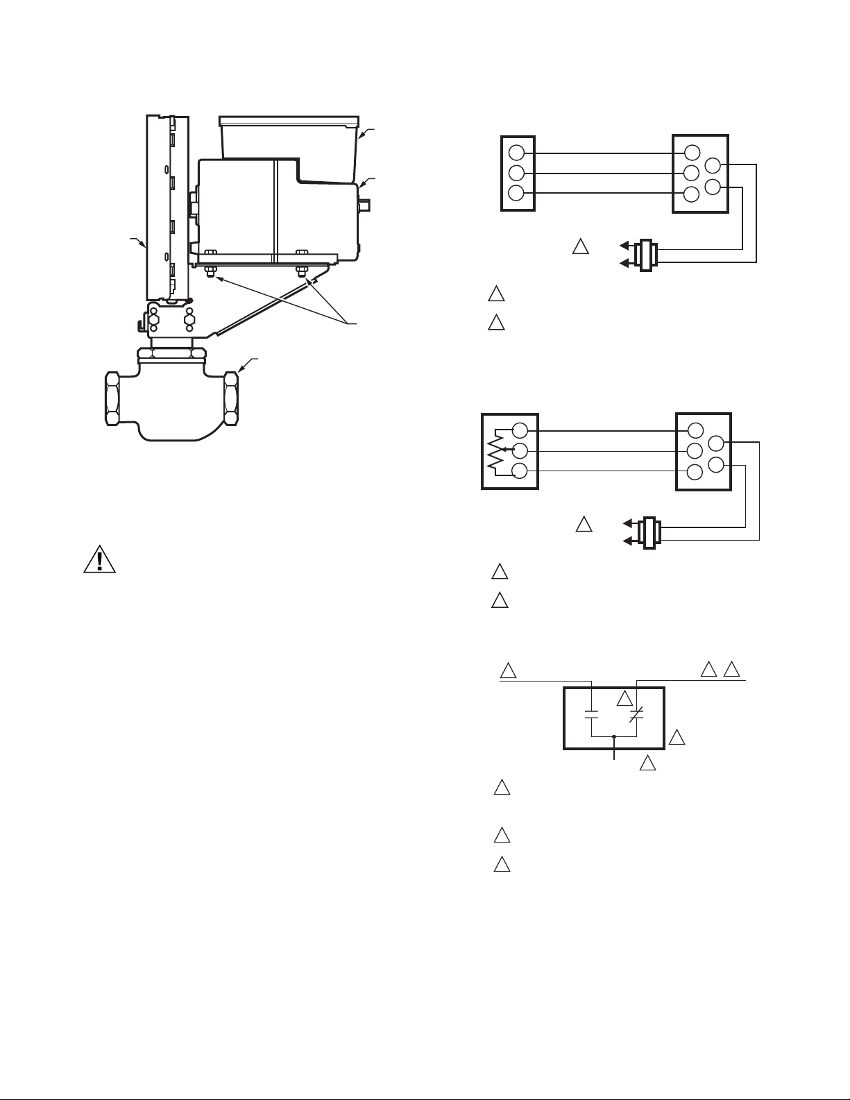
Fig. 4. Mounting the Motor on a Q5001 Valve Linkage.
WIRING
JUNCTION
BOX
MOTOR
M18994
SERIES 90
CONTROLLER
R
W
B
TRANSFORMER
L1
(HOT)
1
L2
POWER SUPPLY. PROVIDE DISCONNECT MEANS AND
1
OVERLOAD PROTECTION AS REQUIRED.
TRANSFORMER MAY BE INTERNAL OR EXTERNAL
2
Fig. 5. Typical Series 90 Wiring.
135 OHM
POTENTIOMETER
W
R
B
TRANSFORMER
L1
(HOT)
1
L2
MOTOR
R
W
B
MOTOR
W
B
T1
T2
M770A
T1
R
T2
CAUTION
Electrical Shock or Equipment Damage Hazard.
Can shock individuals or short equipment
circuitry.
Disconnect power supply before installation.
IMPORTANT
All wiring must agree with applicable codes, ordinances and regulations.
1. Ensure that the voltage and frequency stamped on the
motor correspond to the power supply characteristics.
2. When connecting several motors in parallel, ensure that
the power supply VA rating is large enough to provide
power to all motors used without overloading.
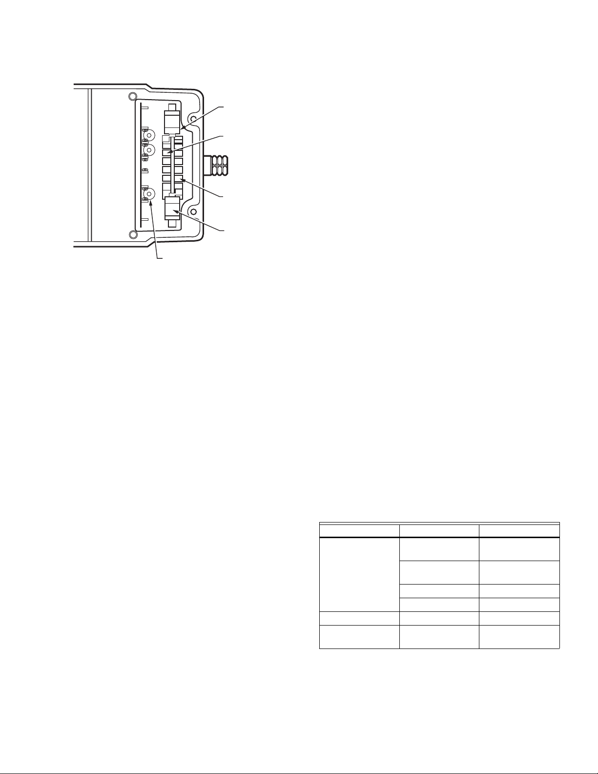
3. Fig. 11 shows that the motor terminals are
quick-connects located on top of the printed circuit
board.
4. To access the wiring compartment:
a. Remove the four screws from the junction box top.
b. Lift off the cover.
5. Refer to Fig. 5 for typical wiring, and Fig. 7 for internal
auxiliary switch connections.
NOTE: Reverse motor rotation by switching wires at either
the motor or the panel. Reverse rotation on the Series
90 models by reversing the wires at terminals W and
B.
POWER SUPPLY. PROVIDE DISCONNECT MEANS AND
1
OVERLOAD PROTECTION AS REQUIRED.
TRANSFORMER MAY BE INTERNAL OR EXTERNAL
2
Fig. 6. Wiring for Potentiometer Control.
2
BLUE LEAD
RED LEAD
USE NEC CLASS 1 WIRING UNLESS POWER SUPPLY
1
MEETS CLASS 2 REQUIREMENTS. TAPE UNUSED LEADS.
ENSURE THE CURRENT DRAW OF THE EXTERNAL CIRCUIT
IS LESS THAN SWITCH CONTACT RATING.
2
ON TWO-SWITCH MOTORS, SECOND SWITCH HAS BLACK
LEADS WITH BLUE, YELLOW, AND RED TRACERS.
3
SOME AUXILIARY SWITCH ASSEMBLIES INCLUDE ONLY
RED AND YELLOW LEADS. SOME OTHERS DO NOT INCLUDE
THE YELLOW LEAD.
YELLOW LEAD
1
2
2
1
Fig. 7. Auxiliary Switch Schematic.
M13708
3
M17099
7 63-2631—02
Page 8
SERIES 90 MODUTROL IV™ MOTORS
SERIES 90 SLAVE MOTOR CONNECTION FROM 4-20MA
24 VOLT
SET DIP
SWITCH
TO TWO
MOTORS
4-20– 4-20+
T1 T2
R(-)
54321 54321
B W1 W1 W(+)
24 VOLT
T1 T2
R
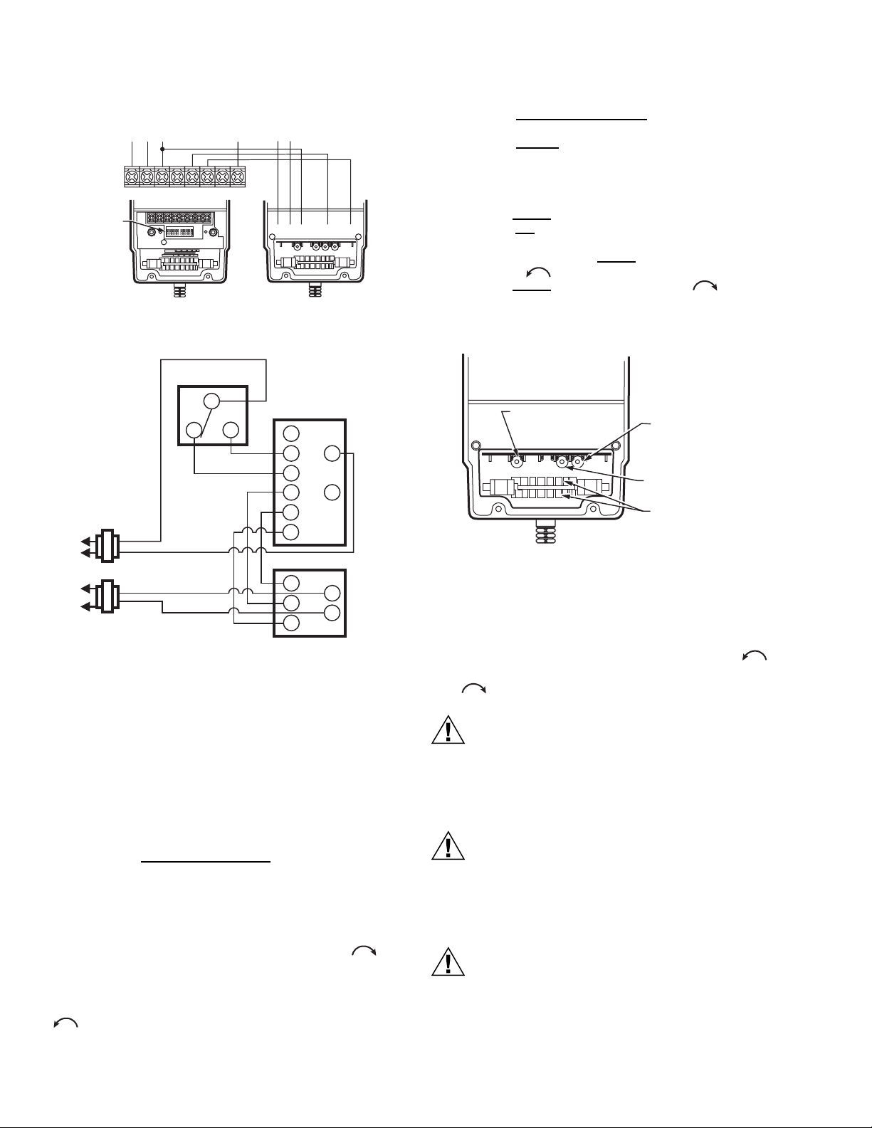
Fig. 8. Series 90 Slave Motor Connection.
SERIES 60
CONTROLLER
R (HOT)
C
R (HOT)
C
R
B
W
M6284
R
1
2
T
G
Y
M9184
W
R
B
Fig. 9. Series 60 Controller.
SETTINGS AND ADJUSTMENTS
BW
M27085
3
4
T1
T2
M27035
To set the stroke between 90 and 160 degrees:
1. Turn the stroke and sensitivity potentiometers fully
clockwise, using a 1/8 inch straight-blade screwdriver.
2. Turn the remote
potentiometer (previously installed on
R-W-B terminals) to maximum position.
3. Turn the sensitivity potentiometer to the selected stroke
(between 90 and 160 degrees) OR until the motor stops.
4. IF the motor stops before the selected stroke is reached,
turn the stroke
potentiometer until the selected stroke is
reached OR
5. IF the selected stroke is reached using the sentivity
potentiometer, turn the stroke
potentiometer counterclockwise until the motor begins to move. Then
turn the stroke
potentiomter clockwise slightly to
have the position correspond to the sensitiviity potentiometer.
6. Make sure the minimum position is correct.
STROKE
POTENTIOMETER
POWER END
OF MOTOR
SENSITIVITY
POTENTIOMETER
TIMING POTENTIOMETER
(M9185D1023 ONLY)
AUXILIARY
SWITCH CAMS
M27388
Fig. 10. Potentiometer Location and Stroke Adjustment
Setup for Non-Spring Return Series 90 Motors.
Adjustable timing for M9185D1023
The timing potentiometer (the second from the right, (Refer to
Fig. 10) sets the timing to 1minute, if turned fully CCW , 2
minutes if turned to its middle point and 4 minutes if turned fully
CW .
Before Setting Stroke
1. Remove the top cover from the motor.
2. Disconnect the controller from the motor.
3. Connect a remote potentiometer to the motor as shown
in Fig. 6 (R-W-B).
The stroke adjustment on the series 2 and series 3 motors is
made using the stroke and sensitivity
under the cove inside the motor. The stroke adjustment on a
series 1 motor was made by adjusting the CAMS.
For Series 2 and Series 3 Motors:
To set the stroke to 160 degrees (maximum position) turn both
stroke and sensitivity potentiometers fully clockwise ,
using a 1/8 inch straight-blade screwdriver.
To set the stroke to 90 degrees (minimum position) turn both
stroke and sensitivity potentiometers fully counter-clockwise
, using a 1/8 inch straight-blade screwdriver.
63-2631—02 8
potentiometers located
CAUTION
Careless Installation Hazard.
Use of excessive force while adjusting cams
damages the motor.
To avoid damaging motor end switches, set cams by
moving only the top of the screwdriver.
CAUTION
Careless Installation Hazard.
Forcibly turning the motor shaft damages the gear
train and stroke limit contacts.
Never turn motor shaft manually (by hand or with a
wrench).
CAUTION
Equipment Damage Hazard.
Can damage the motor beyond repair.
Set cams by moving the top of the screwdriver only.
Pressing screwdriver against cam slot sides or use of
excessive force can damage motor end switches.
Page 9
W
B
R
T
2
T
1
ADJUSTABLE STROKE POTENTIOMETER
NOTE: NOT ALL FEATURES AVAILABLE ON ALL MODELS.
INNER AUXILIARY
SWITCH
INNER AUXILIARY
SWITCH CAM (BLUE)
OUTER AUXILIARY
SWITCH CAM (RED)
OUTER AUXILIARY
SWITCH
Fig. 11. Terminals and Adjustments.
POWER
END
M27389
SERIES 90 MODUTROL IV™ MOTORS
6. For a 10° switch differential:
a. Spring return models: rotate the cam approximately
180° so that the slow-rise portion of the cam actuates
the switch. Then check continuity of the auxiliary
switch contacts R-B.
b. Non-spring return models: check continuity of the
auxiliary switch contacts R-B.
7. Rotate the cam as follows:
a. If the contacts are open, rotate the cam counterclock-
wise until the R-B contacts close.
b. If the contacts are closed, rotate the cam clockwise
until the R-B contacts open.
8. Check for proper auxiliary equipment differential and
switching by driving the motor though the full stroke in
both directions.
9. Disconnect the potentiometer, reconnect the controller,
and replace the motor top cover.
NOTE: Changing the differential from 1° to 10° reverses the
switching action. For example, with a 10° differential,
switch contacts R-B make and R-W break on a counterclockwise (closed) rotation. With a 1° differential,
switch contacts R-W make and R-B break on a counterclockwise (closed) rotation.
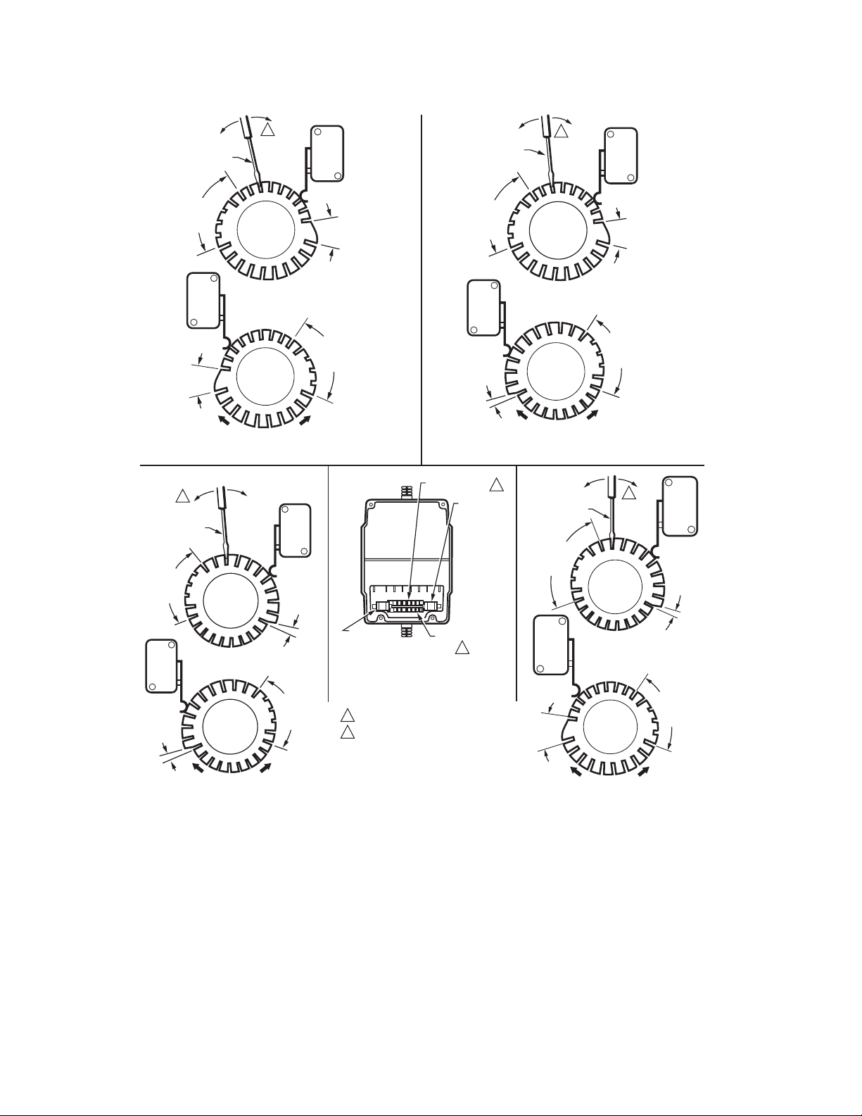
Auxiliary Switches
Adjustable cams actuate the auxiliary switches. These cams
can be set to actuate the switches at any angle within the
stroke of the motor. Select switch differential of 1° or 10°.
Motors with factory-added auxiliary switches are shipped in the
closed position (fully counterclockwise, as viewed from the
power end). Auxiliary cam default actuates the switches 30°
from full open with a 1° differential. With the motor in the closed
(fully counterclockwise) position, the auxiliary switch breaks
contacts R-B. Refer to Fig. 7 (or the auxiliary switch Instruction
Sheet) for auxiliary switch wiring.
NOTE: Auxiliary switches can only be added to motors that
include auxiliary switch cams. (These cams cannot be
field-added.)
NOTE: Series 3 Motors are shipped with auxiliary switch
cams that permit acceptance of 220736A,B Internal
Auxiliary Switch Kits. Refer to Form no. 63-2228 for
220736A,B Installation Instructions.
Auxiliary Switch Adjustment
1. Remove the top cover from the motor to gain access to
the motor terminals and auxiliary cams.
2. Disconnect the controller from the motor.
3. Connect a potentiometer to the motor as shown in Fig. 6.
4. Using the potentiometer, drive the motor to the position
where the auxiliary equipment is to be switched.
5. For a 1° switch differential, check continuity of the auxiliary switch contacts R-B and rotate the cam as follows:
a. If the contacts are open, rotate the cam clockwise
until the R-B contacts close.
b. If the contacts are closed, rotate the cam counter-
clockwise until the R-B contacts open.
OPERATION
Use Series 90 Modutrol IV Motors for standard Series 90
operation (See Table 7):
1. Two potentiometers, one in the controller and one in the
motor, along with the motor resistor network, form a
bridge circuit. As long as the value of the controlled
medium remains at the setpoint, the circuit remains balanced and the motor does not run.
2. When the controlled medium value changes, the controller potentiometer wiper moves, unbalancing the bridge
circuit.
3. The imbalance is amplified and the microcontroller then
drives the motor in the direction necessary to correct the
controlled medium change.
4. As the motor shaft rotates, it turns the feedback potentiometer, rebalancing the bridge circuit, stopping the
motor.
Table 6. Modutrol IV Motor Operation.
Motor Type Signal Resulting Action
Non-Spring Return
or Spring Return
Non-Spring Return Power Loss stops (none)
Spring Return Power Loss spring returns
Open W and short
drives open
R to B
Open B and short
drives closed
R to W
Jumper R-W-B drives to midstroke
None drives closed
(closed)
9 63-2631—02
Page 10
SERIES 90 MODUTROL IV™ MOTORS
T1
T2
R
B
W
M17626
Fig. 12. Attaching a Shunt Resistor to TRADELINE Motors.
Table 7. Cam Arrangements.
Motor
Inner
Cam
Outer
M9164D1009, M9174D1007 Red Blue
ALL OTHER M9164 Blue Red
M9184, M9194
M9185
M9484, M9494
All Other M9174 Blue Blue
Cam
63-2631—02 10
Page 11
SERIES 90 MODUTROL IV™ MOTORS
1/8 INCH
STRAIGHT-BLADE
SCREWDRIVER
SLOW RISE
PORTION
(APPROX.
10 DIFF.)
FAST RISE
PORTION
(APPROX. 1 DIFF.)
2
1/8 INCH
STRAIGHT-BLADE
SCREWDRIVER
SLOW RISE
PORTION
(APPROX.
10 DIFF.)
LEFT/OUTER
AUXILIARY
SWITCH
LEFT/OUTER
AUXILIARY
SWITCH
MOTOR
OPEN
RIGHT/INNER
AUXILIARY
SWITCH
INNER
AUXILIARY
CAM
(BLUE)
2
INNER
AUXILIARY
CAM
(RED)
OUTER
AUXILIARY
CAM
(RED)
POWER
END
SLOW RISE
MOTOR
CLOSE
FAST RISE
PORTION
(APPROX.
1 DIFF.)
RIGHT/INNER
AUXILIARY
SWITCH
FAST RISE PORTION
(APPROX. 1 DIFF.)
PORTION
(APPROX.
10 DIFF.)
LEFT/OUTER
AUXILIARY
SWITCH
POWER
END OF
MOTOR
1/8 INCH
STRAIGHT-BLADE
SCREWDRIVER
SLOW RISE
PORTION
(APPROX.
10 DIFF.)
FAST RISE
PORTION
(APPROX.
1 DIFF.)
INNER AUXILIARY
CAM
RIGHT/INNER
AUXILIARY
SWITCH
OUTER AUXILIARY
CAM
1
LEFT/OUTER
AUXILIARY
SWITCH
MOTOR
OPEN
1
2
INNER
AUXILIARY
CAM
(RED)
OUTER
AUXILIARY
CAM
(BLUE)
MOTOR
CLOSE
POWER
END
1/8 INCH
STRAIGHT-BLADE
SCREWDRIVER
SLOW RISE
PORTION
(APPROX.
10 DIFF.)
LEFT/OUTER
AUXILIARY
SWITCH
RIGHT/INNER
AUXILIARY
SWITCH
FAST RISEPORTION
(APPROX. 1 DIFF.)
SLOW RISE
PORTION
(APPROX.
10 DIFF.)
2
INNER
AUXILIARY
CAM
(BLUE)
RIGHT/INNER
AUXILIARY
SWITCH
FAST RISE
PORTION
(APPROX.
1 DIFF.)
FAST RISE
PORTION
(APPROX.
1 DIFF.)
MOTOR
OPEN
OUTER
AUXILIARY
CAM
(BLUE)
POWER
END
MOTOR
CLOSE
SLOW RISE
PORTION
(APPROX.
10 DIFF.)
1
CAM ARRANGEMENT VARIES WITH MODEL.
2
MOVE SCREWDRIVER AT TOP ONLY TO
ADJUST CAM.
NOTE: CAMS ARE OFFSET VERTICALLY TO
PROVIDE BETTER VIEW OF INNER CAM.
FAST RISE
PORTION
(APPROX.
1 DIFF.)
Fig. 13. Auxiliary Switch Adjustment.
11 63-2631—02
MOTOR
OPEN
OUTER
AUXILIARY
CAM
(RED)
POWER
END
MOTOR
CLOSE
SLOW RISE
PORTION
(APPROX.
10 DIFF.)
M17672
Page 12

SERIES 90 MODUTROL IV
™
MOTORS
CHECKOUT
After the installation and linkage adjustment, check the entire
motor and control hookup. Proper checkout ensures that:
• The motor operates the load (damper or valve) properly.
• The motor responds properly to the controller as the input
varies (See Table 7).
• The auxiliary switch, if used, operates at the desired point
of motor rotation.
1. Inspect motor, linkage, and valve or damper to ensure
all mechanical connections are correct and secure.
NOTE: In damper installations, the pushrod should not
extend more than a few inches past the ball
joints.
2. Ensure that there is adequate clearance for the linkage
throughout the entire motor stroke without binding or
striking other objects.
3. Ensure the motor transformer is properly sized.
NOTE: If a common transformer is used to power mul-
tiple motors, ensure the power input is in
phase with all motors.
4. Drive the motor fully open and fully closed
(See Table 7).
NOTE: Refer to controller or system instructions for
additional checkout procedures.
5. For spring return motors, ensure that the valve or
damper returns to normal position upon power interruption.
6. Return the controller to the desired setting before leaving the job.
REPLACEMENT
Damper Application
1. Turn off power and remove wiring from the old motor.
2. Remove the crank arm from shaft of old motor and
remove the old motor.
3. Determine necessity of the mounting bracket. If the linkage can reach the new motor shaft position and the
crank arm has clearance for the necessary rotation, the
bracket is not required. Use the 220738A Adapter
Bracket or the 221455A Crank Arm if the crank arm
must rotate through the bottom plane of the motor.
a. If no bracket is required, mount the new motor
directly to the equipment and refer to the Installation, Settings and Adjustments, and the Operation
and Checkout sections of these instructions.
b. If the bracket is required, refer to the Adapter
Bracket section and Fig. 3 in addition to the Installation, Settings and Adjustments, and the Operation
and Checkout sections of these instructions.
4. Use No. 12 or 1/4 inch machine screws or bolts to
mount the new motor.
5. Mount damper crank arm and linkage to the new motor
shaft.
6. Use the Checkout procedures to test the crank arm and
linkage adjustment.
Valve Application
When replacing a motor in a valve application, the linkage
determines the necessity of the 220738A Adapter Bracket.
With Q100, Q601 or Q618 Linkages, it is necessary to use the
220738A to raise the motor shaft to the appropriate height.
Valve applications with a Q5001 Linkage do not require the
220738A Adapter Bracket. To operate Honeywell V5011
two-way or V5013 three-way valves through full stroke, use a
160° stroke motor.
Automation and Control Solutions
Honeywell International Inc. Honeywell Limited-Honeywell Limitée
1985 Douglas Drive North 35 Dynamic Drive
Golden Valley, MN 55422 Toronto, Ontario M1V 4Z9
customer.honeywell.com
® U.S. Registered Trademark
© 2008 Honeywell International Inc.
63-2631—02 M.S. Rev. 04-08
 Loading...