

Page 1

-English-
Le Sucre™
User guide
800-19461-B
10/2015
Page 2

2
Contents
Introduction...............................................................................3
Controlling your system ..........................................................4
Badge reader ......................................................................................................... 4
Keypad (only available on Sucre Box) ................................................................ 7
Keyfobs ................................................................................................................ 10
Sucre Box light indication .................................................................................. 12
Installing Detectors & Sirens ................................................13
Door contact ........................................................................................................ 13
Motion detectors ................................................................................................. 13
Motion detector with Image ................................................................................ 14
Glass break detector ........................................................................................... 15
Shock sensor ....................................................................................................... 17
Carbon monoxide detector ................................................................................. 19
Smoke detector ................................................................................................... 22
Indoor siren ......................................................................................................... 24
FAQ ..........................................................................................26
Page 3

3
Introduction
This document is intended to help you with the installation and the operation of your Le
Sucre system.
The system comprises three types of components:
Le Sucre central unit which is the core of the system: it communicates with all the
other components of the system and transmits the alarms in case of a problem.
Control & Indication Equipments enable to operate the system (arming and
disarming for example).
Detectors are installed in the premises and communicate with the central unit in
case of problem (intrusion, fire, etc). Sirens are used to sound locally when an
alarm occurs.
Page 4

4
Controlling your system
Badge reader
The Badge reader comprises an integrated siren that will sound in case of alarm.
Installation requirements
Install the Badge reader:
Near the door generally used to enter into the house
With at least 30 cm clear space around it
About 1.50 m from the floor (for a person 1.70 m to 1.80 m tall)
On a wall
Do not install the Badge reader:
Outdoors
Near a source of heat (e.g. chimney, radiator, convector, oven, cooking hob)
Near a water point (e.g. bathroom)
How to install
A help video can be found here:
http://honeywell.total-connect.eu/video/SPR-S8EZ.mp4
How to use the Badge reader
The system can be set in two different modes:
- Total arm / total set: this mode is used when you leave your premises.
- Partial arm / partial set: this mode is used when you want to use your system while
in your premises (at night for example). In this case the motion detectors are not
active and only the door contacts are operational (or the detectors that you have set
to “night mode”)
Page 5
5
1. Press this button.
2. Present your fob in front of this area on the Badge reader.
3. The green light flashes during the exit delay.
4. Exit the premises before the end of the beeps (faster at the
end).
1. Press this button.
2. Present your fob in front of this area on the Badge reader.
3. The green light flashes during the exit delay and remains
flashing.
1. The green light is turned on (lit or flashing).
2. Present your badge in front of this area on the Badge reader.
3. The green light turns off.
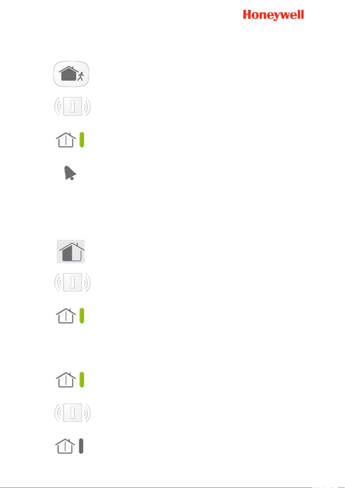
To set the system when you leave your premises: Total arm
To set the system when you are still in your premises: Partial arm
To unset the system
Page 6

6
Set/Unset status (green):
Fast flashing during the entry/exit delay
Slow flashing when the system is in partial arm mode
Off when the system is unset and after the exit delay
Defaults status (red):
On when a default is present (detailed on the webserver)
Slow flashing in case of Badge reader low battery
Off in normal situation
Intrusion status (orange):
On when an intruder alarm occurred when the system was set
Will be reset at the next set action
Technical status (orange):
On when an alarm smoke detection occurred
Fast flashing during for other alarms (detailed on the webserver)
The Badge reader lights
Page 7
7
Keypad (only available on Sucre Box)
The Keypad comprises an integrated siren that will sound in case of alarm.
Installation requirements
Install the keypad:
Near the door generally used to enter into the house
With at least 30 cm clear space around it
About 1.50 m from the floor (for a person 1.70 m to 1.80 m tall)
On a wall
Do not install the keypad:
Outdoors
Near a source of heat (e.g. chimney, radiator, convector, oven, cooking hob)
Near a water point (e.g. bathroom)
How to install
A help video can be found here:
http://honeywell.total-connect.eu/video/GKP-S8M.mp4
How to use and program the keypad
The following section describes how to install and use your wireless keypad. The keypad is
used to arm and disarm your security system using a valid access code or a key TAG.
The first step is to register your keypad and tags on the system via the web portal as for all
other devices.
If you want to use codes to arm and disarm your system you will need to program the
keypad. Please refer to the printed manual that is downloadable here:
http://www.honeywell.com/security/emea/hscdownload
Page 8
8
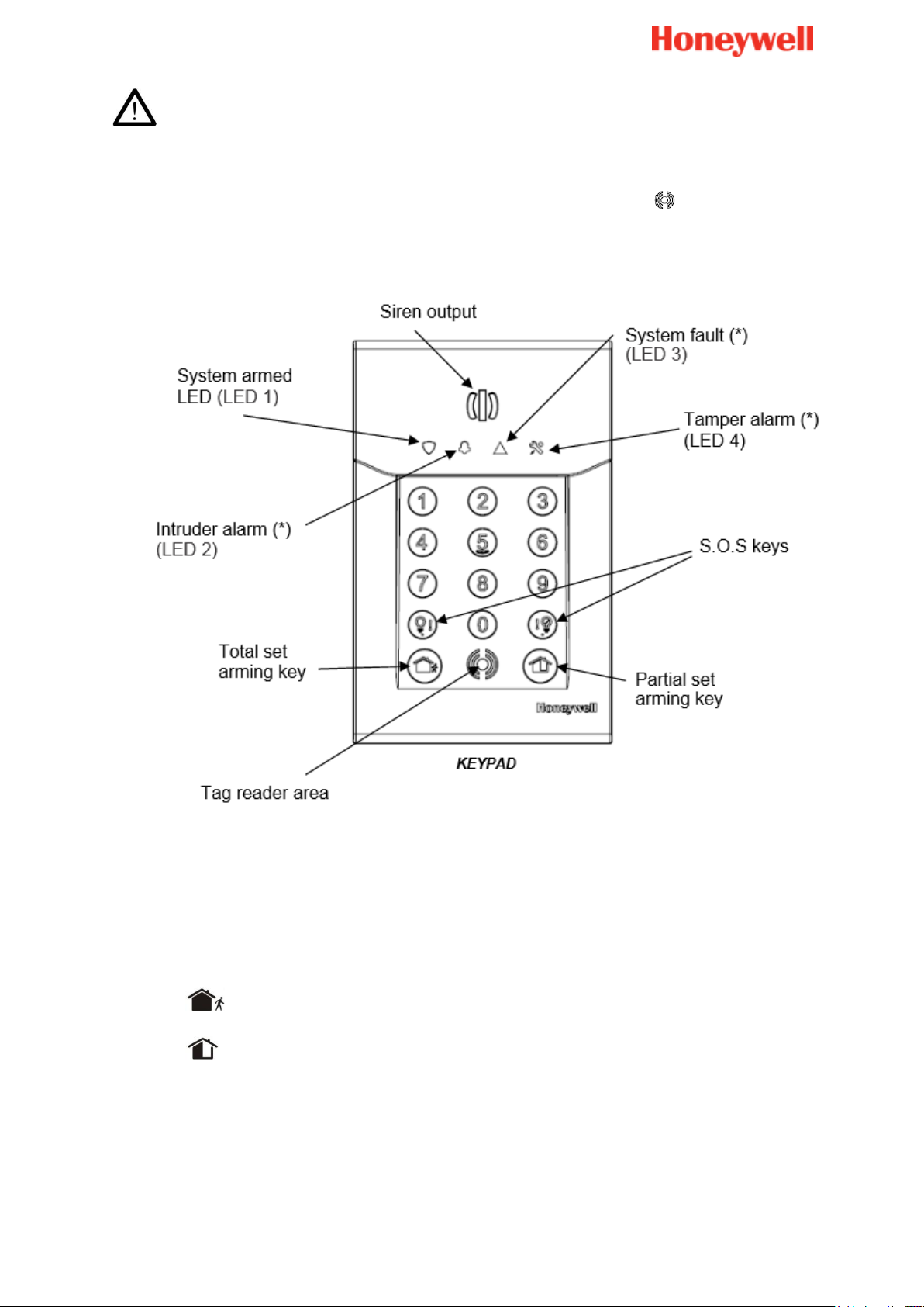
By default, user 1 has code 1234. Don’t forget to change it at installation!
Arms the total set
Arms the partial set
The keypad is equipped with a proximity tag reader, located next to the symbol; the
keypad also features an integrated siren as a deterrent and 4 LEDs to inform you on system
status.
Arming using your code or tag
Press an arming key on the keypad and enter the code or present a registered TAG.
The arming tone is emitted by the keypad followed by the exit delay beeps.
The zone set arming is completed automatically at the end of the exit delay.
Note:
Always make sure that your Total arming request is followed by the arming tone.
Page 9

9
Disarming using your code or tag
To disarm your system:
Enter a valid code or present a registered TAG.
The disarming tone is emitted by the keypad siren.
Disarming the system will also stop the sirens if an alarm is triggered.
Notes:
Always make sure that your disarming request is followed by the disarming tone.
Always disarm the system when re-entering the premises.
Holding the TAG in front of the keypad will not reverse the status.
Page 10
10
Whilst in the installation mode, Press total arm and partial arm buttons
simultaneously for 2 seconds.
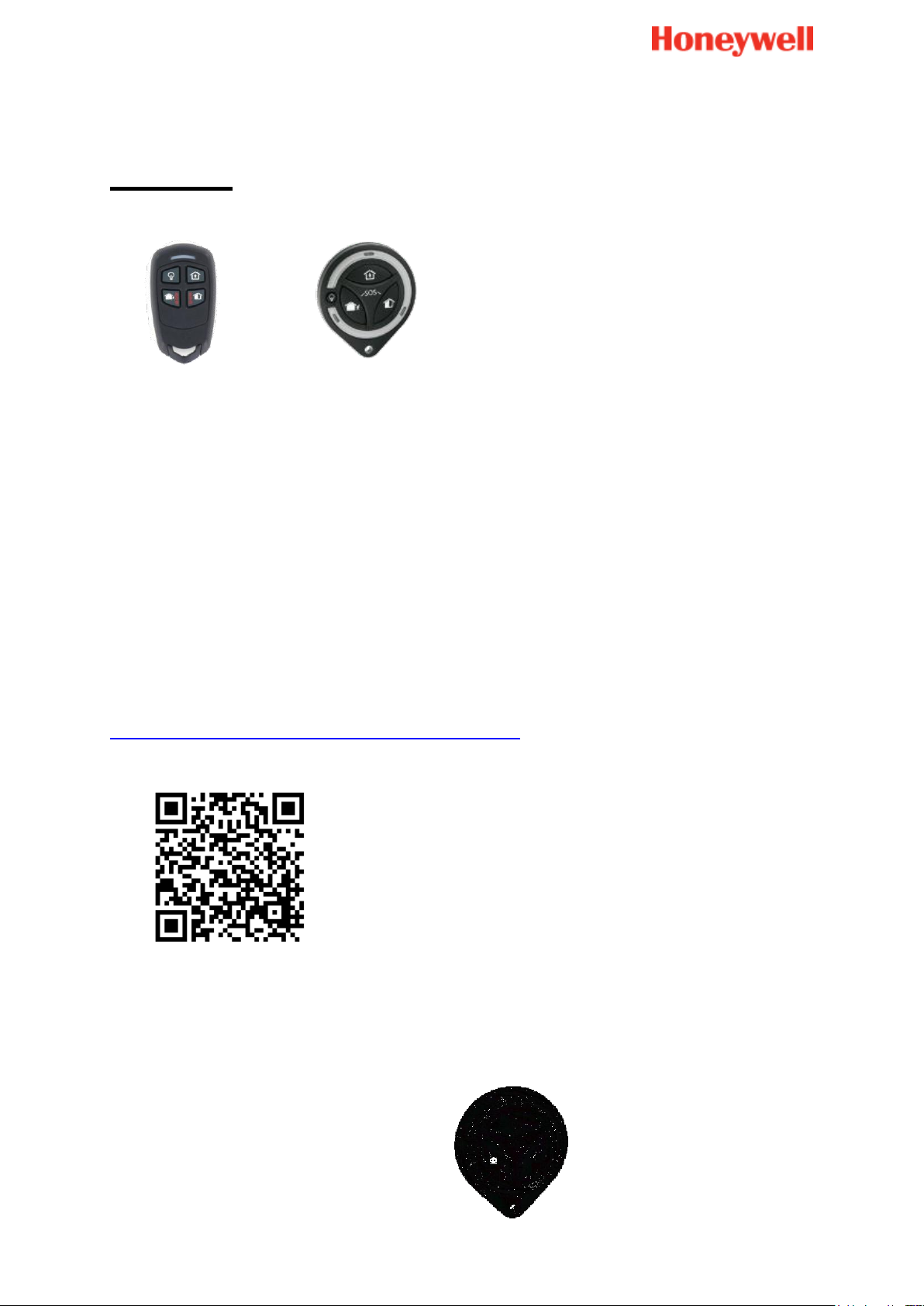
Keyfobs
Caution
Do not place the keyfob in a location where it may be subjected to high
temperatures
Be careful not to drop your keyfob. Handle it with care otherwise you may damage it,
discharge the battery, or cause a malfunction
Keep the keyfob away from moisture, dust and water
Use only the recommended battery (CR2032 by Panasonic or GP)
How to install
A help video can be found here:
http://honeywell.total-connect.eu/video/TCC800M.mp4
To register the keyfob:
Page 11

11
The corresponding LEDs will light up for 3 seconds.
You will hear 2 short beeps from the Badge
reader.
Page 12
12
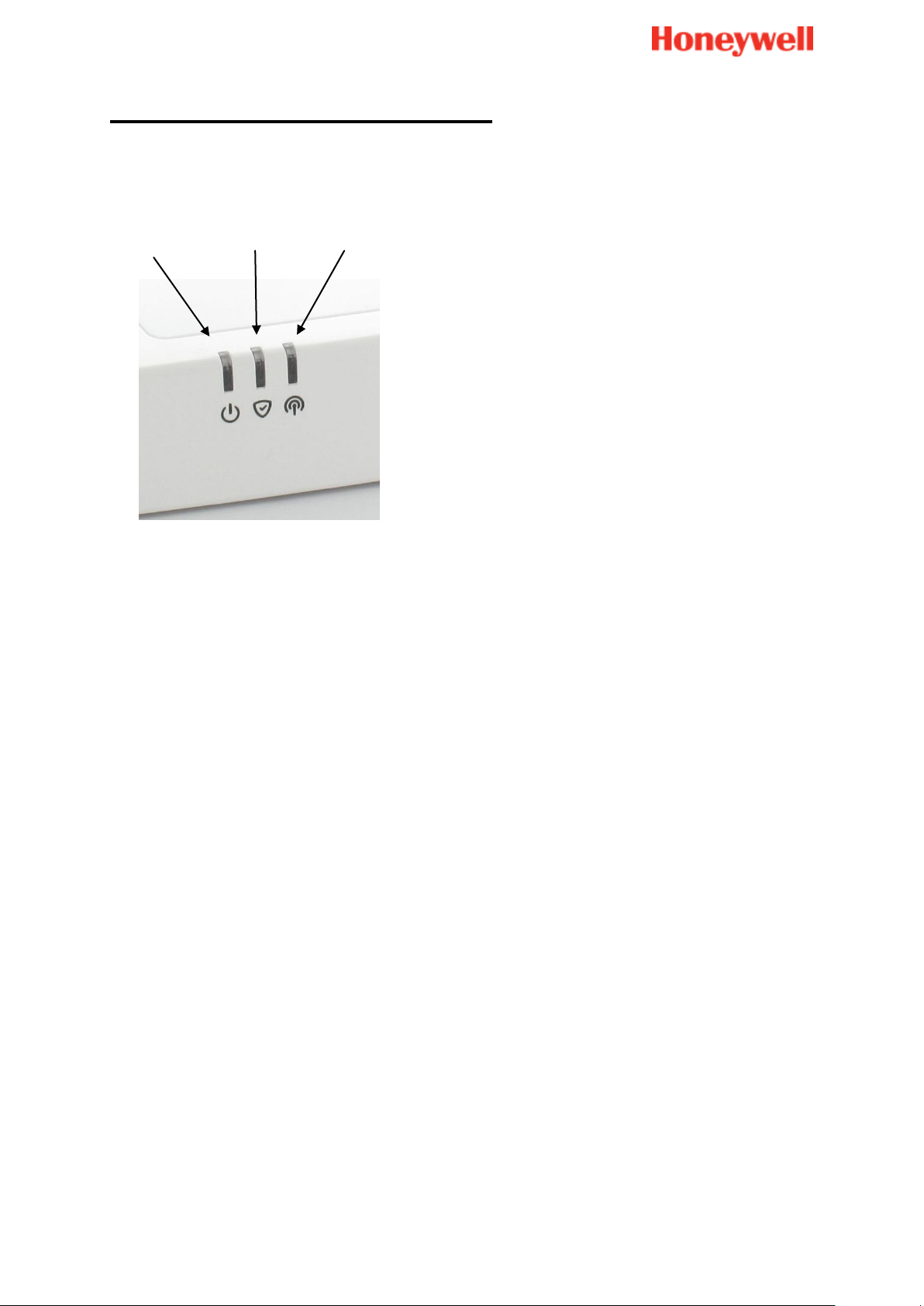
Sucre Box light indication
Light 1
Light 2
Light 3
The Sucre Box panel has three lights as shown below.
- Light 1: Indication on the power supply state of the panel
o Green fixed: the panel is correctly power supplied.
o Orange blinking: the panel is on battery power only.
- Light 2: Indication of the arming state of the system
o Off: The system is disarmed
o Green fixed: the system is in “Total arm”
o Green blinking: the system is in “Partial arm”
o Orange blinking: an intrusion was detected
- Light 3: Indication of the GPRS network (at installation only)
o Off: no GPRS module (Sucre Box SUE8EU-STD-E version)
o Orange blinking: GPRS network not found
o Green fixed: GPRS network found
Note: For Sucre Box SUE8EU-STD-E version, the light will always be off as no
SIM card is used
Important note: At first installation, Sucre Box will update automatically with the
latest version of firmware. This phase generally lasts 10 min but can last up to 20
min. During this time, all LEDs are turned off.
Page 13
13
Installing Detectors & Sirens
Note: After correctly installing a device you will hear short beeps from the Badge reader or
the keypad
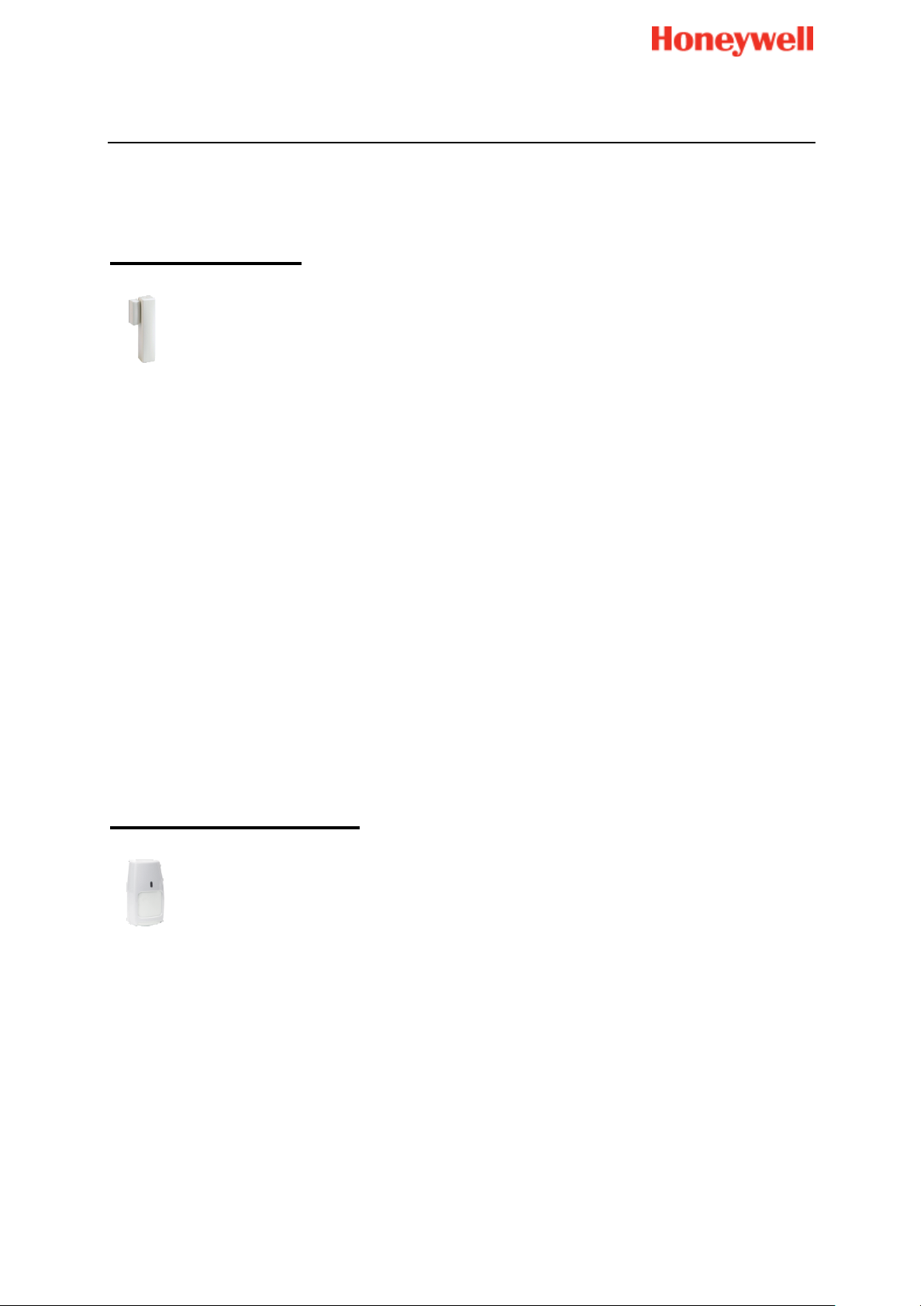
Door contact
Please refer to the printed manual supplied with the product for full guidance.
Install the contact:
Inside the room to be protected
Opposite the hinges for faster opening detection
Attach the magnet to the opening part, for example the door and not the frame
Attach the sensor to the door frame and not the door
With the magnet opposite the mark shown on the detector
With less than 2 cm between the magnet and the detector when the door/window
closed
So that opening the door or window fully does not damage the magnet
Do not install the contact:
Outdoors
Near a water point (e.g. bathroom)
Motion detectors
Please refer to the printed manual supplied with the product for full guidance.
Install the detector:
In a circulation area, preferably pointing towards entrances (e.g. door, window)
Preferably in a corner to optimize the detection area
In a place where animals cannot get within a distance of 1.80 m by climbing on
furniture, stairs, boxes or any other object
In a detection area free of obstacles (e.g. curtains, wardrobes)
At a height of between 2.30 m and 2.50 m above the ground
Do not install the detector:
In a room smaller than the detection area (at least 4 m²)
Page 14
14
Outdoors
Near a source of heat (e.g. chimney, radiator, convector, oven, cooking hob)
Near a source of cold air (e.g. air conditioning)
Opposite a window
Near a water point (e.g. bathroom)
Do not paint the detector
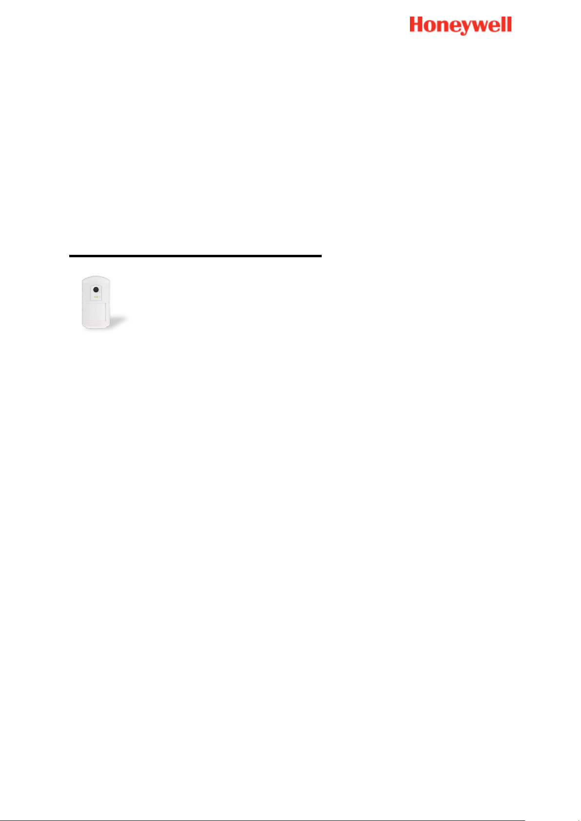
Motion detector with Image
Please refer to the printed manual supplied with the product for full guidance.
Install the detector:
In a circulation area, preferably pointing towards entrances (e.g. door, window)
Preferably in a corner to optimize the detection area
In a place where animals cannot get within 1.80 m of it by climbing on furniture,
stairs, boxes or any other object
In a detection area free of obstacles (e.g. curtains, wardrobes)
At a height of between 2.30 m and 2.50 m above the ground
Do not install the detector:
In a room smaller than the detection area (at least 4 m²)
Outdoors
Near a source of heat (e.g. chimney, radiator, convector, oven, cooking hob)
Near a source of cold air (e.g. air conditioning)
Opposite a window
Near a water point (e.g. bathroom)
Do not paint the detector
Page 15
15
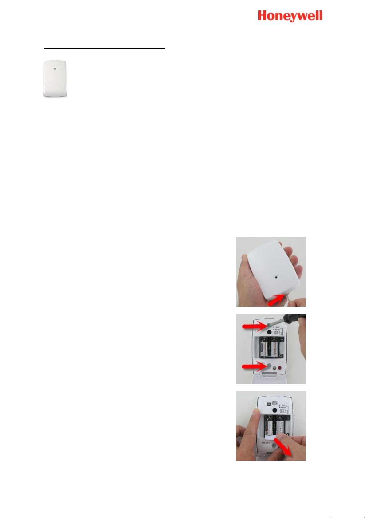
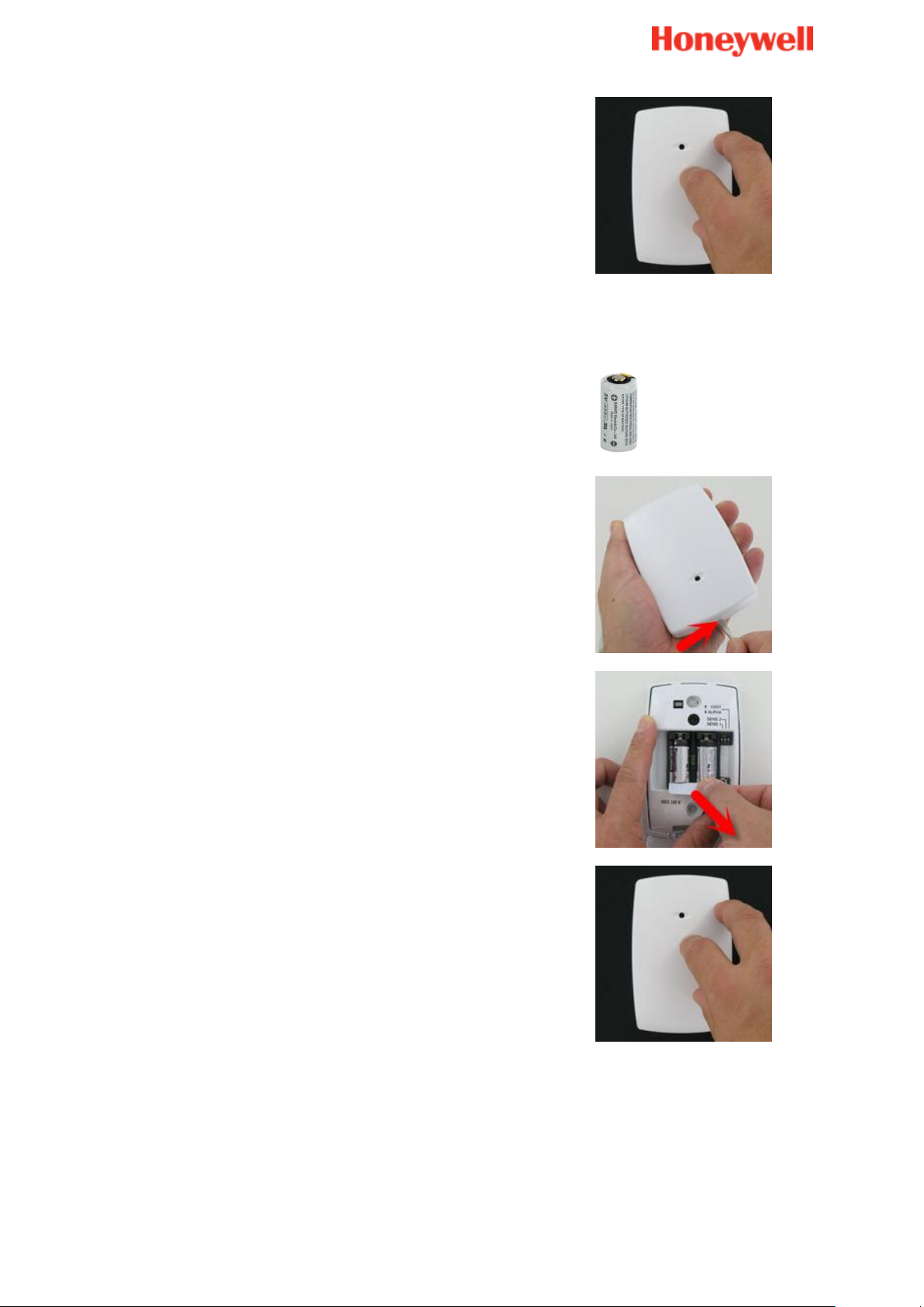
Glass break detector
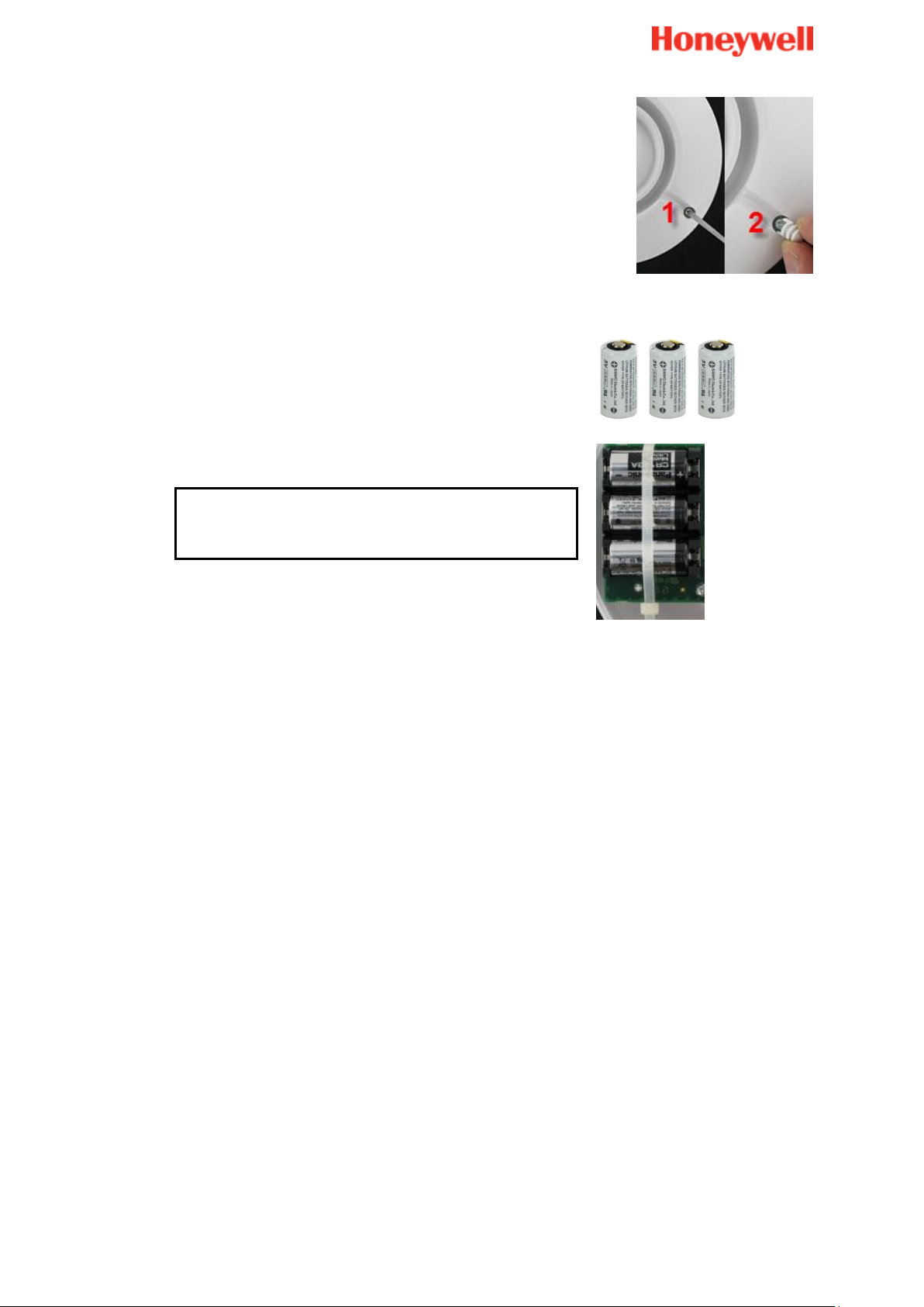
1. Open the sensor.
2. Screw the base to the wall.
3. Hold the batteries in place and pull out the battery
tab to power up the sensor.
Installation requirements
Mount the detector between the protected glass and any heavy window coverings that
may be present. When heavy window coverings are present, the detector can be
mounted on the frame of the window.
Do not mount the detector:
On posts or pillars
In rooms with noisy equipment (air compressors, power tools, etc.), if this equipment
is operated when the detector is armed
Where the detector’s view of the glass may be obstructed intentionally
How to install
1. Orient the microphone for the best line-of-site to the protected glass. If ceiling
mounted the end with the microphone should face the protected glass.
Page 16
16
4. Close the sensor.
How to change the batteries
Average battery lifetime: 4 years
Type: CR123A
Quantity: 2
1. Open the sensor.
2. Change the batteries (CR123 type).
3. Close the sensor.
Page 17
17
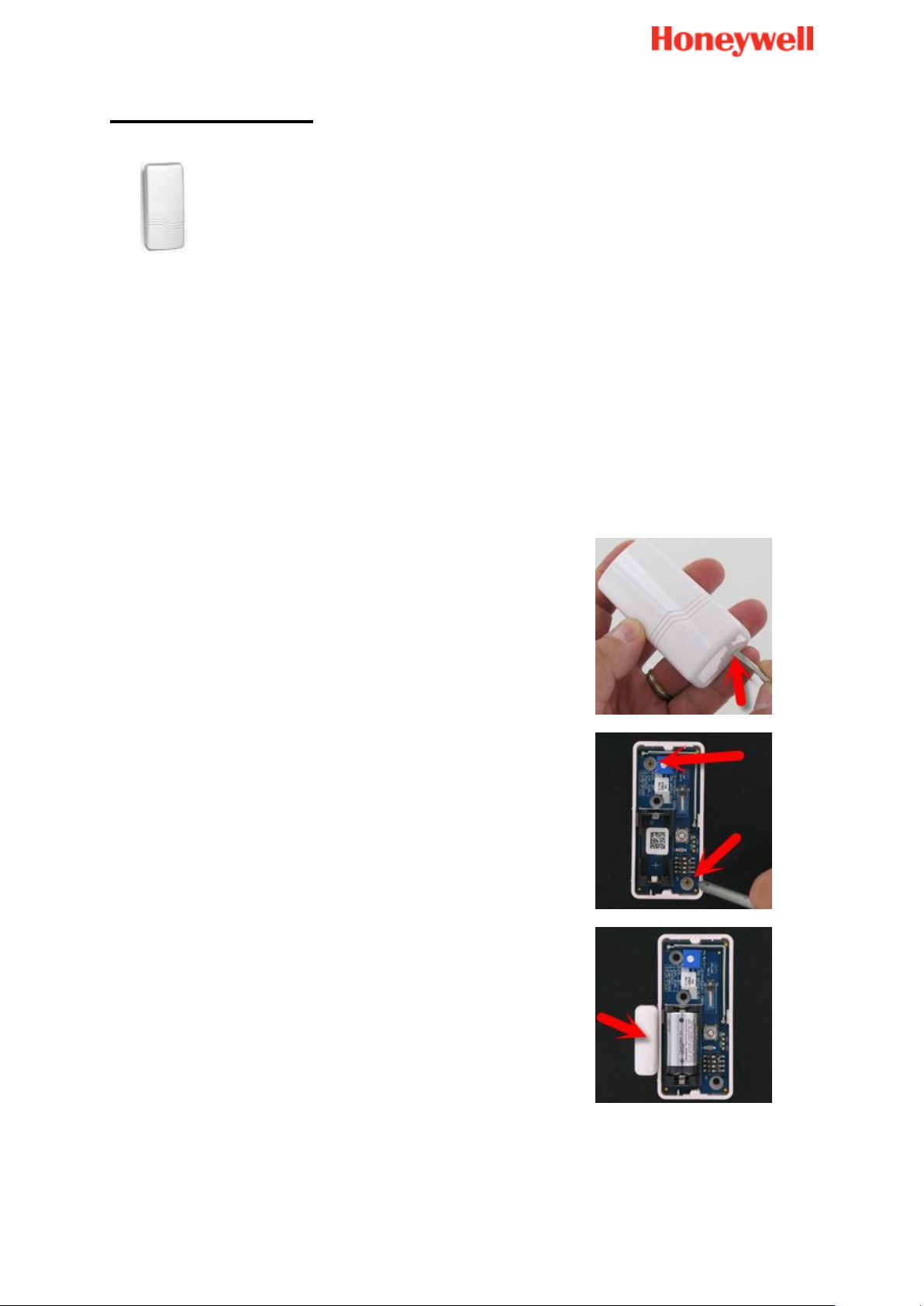
Shock sensor
1. Remove the cover of the sensor.
2. Mount the sensor on a solid surface with the screws
supplied. There are two mounting holes.
3. For SHKC8M only, mount the magnet (supplied)
adjacent to the sensor’s alignment strip.
Installation requirements
The SHK(C)8M series is designed to protect window and door surroundings, and is used
to detect forcible attacks upon the surface on which it is mounted.
It is capable of detecting two different types of forcible attacks:
Strong attack: the device will send an alarm for any single shock event whose
intensity exceeds the factory set strong attack sensitivity level
Repeated attacks: the device will send an alarm after a defined number
(controllable) of consecutive shocks, whose intensity exceeds the factory set
repeated attack sensitivity level detected within a period of 8 s
How to install
Page 18
18
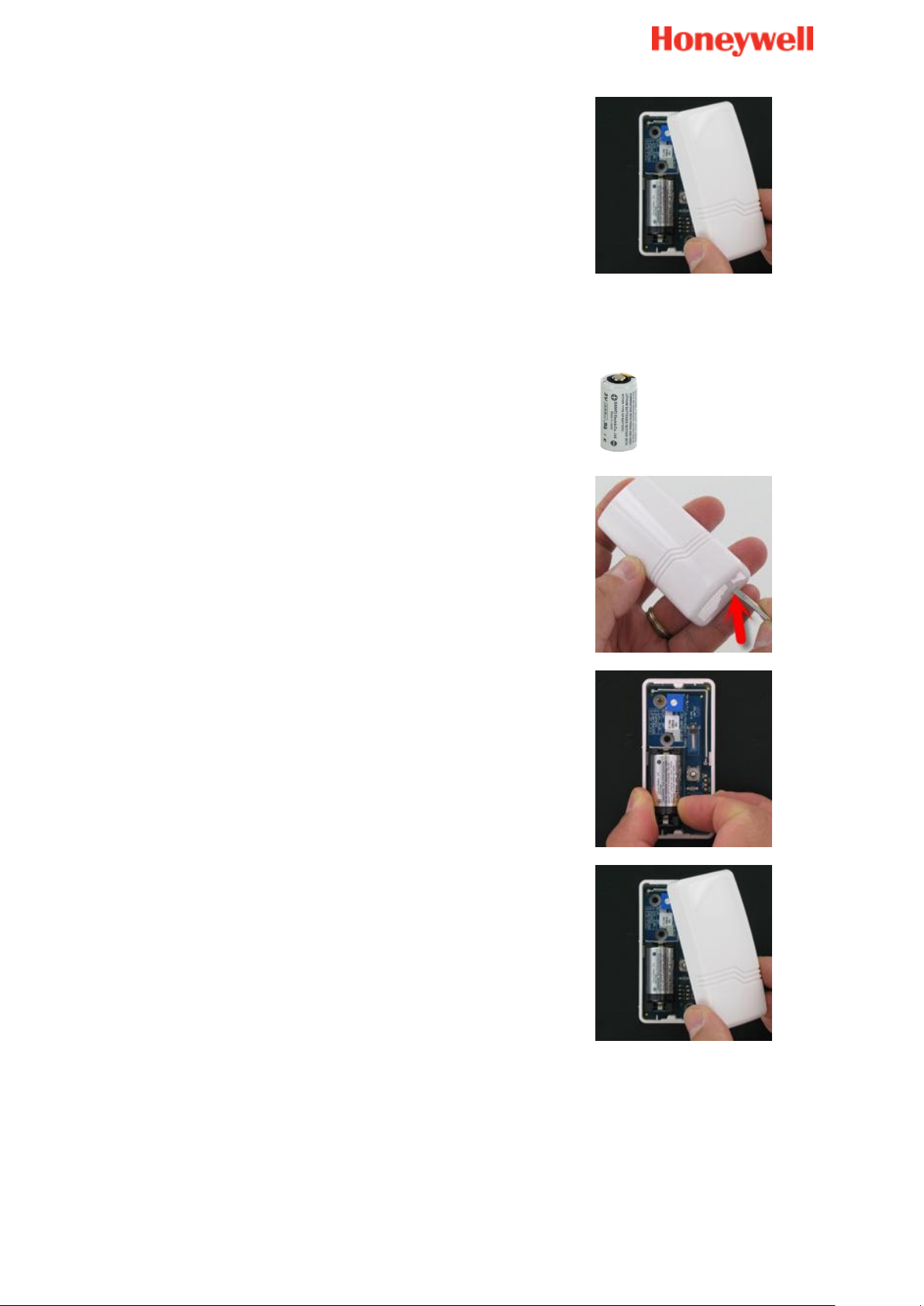
4. Replace the cover.
How to change the batteries
Average battery lifetime: 4 years
Type: CR123A
Quantity: 1
1. Remove the cover.
2. Replace the battery.
3. Replace the cover.
Page 19
19
Carbon monoxide detector
CO Alarm
300 mm
150 mm
STILL AIR
DO NOT
LOCATE
HERE
1 to 3m
1 to 3m
CO Alarm
CO Alarm
Approximately
1 to 2 m
300 mm
Installation requirements
Where to place the carbon monoxide detector:
Ideally, install a carbon monoxide alarm in:
Every room containing a fuel burning appliance
Page 20
20
Remote rooms where occupants spend a considerable amount of time
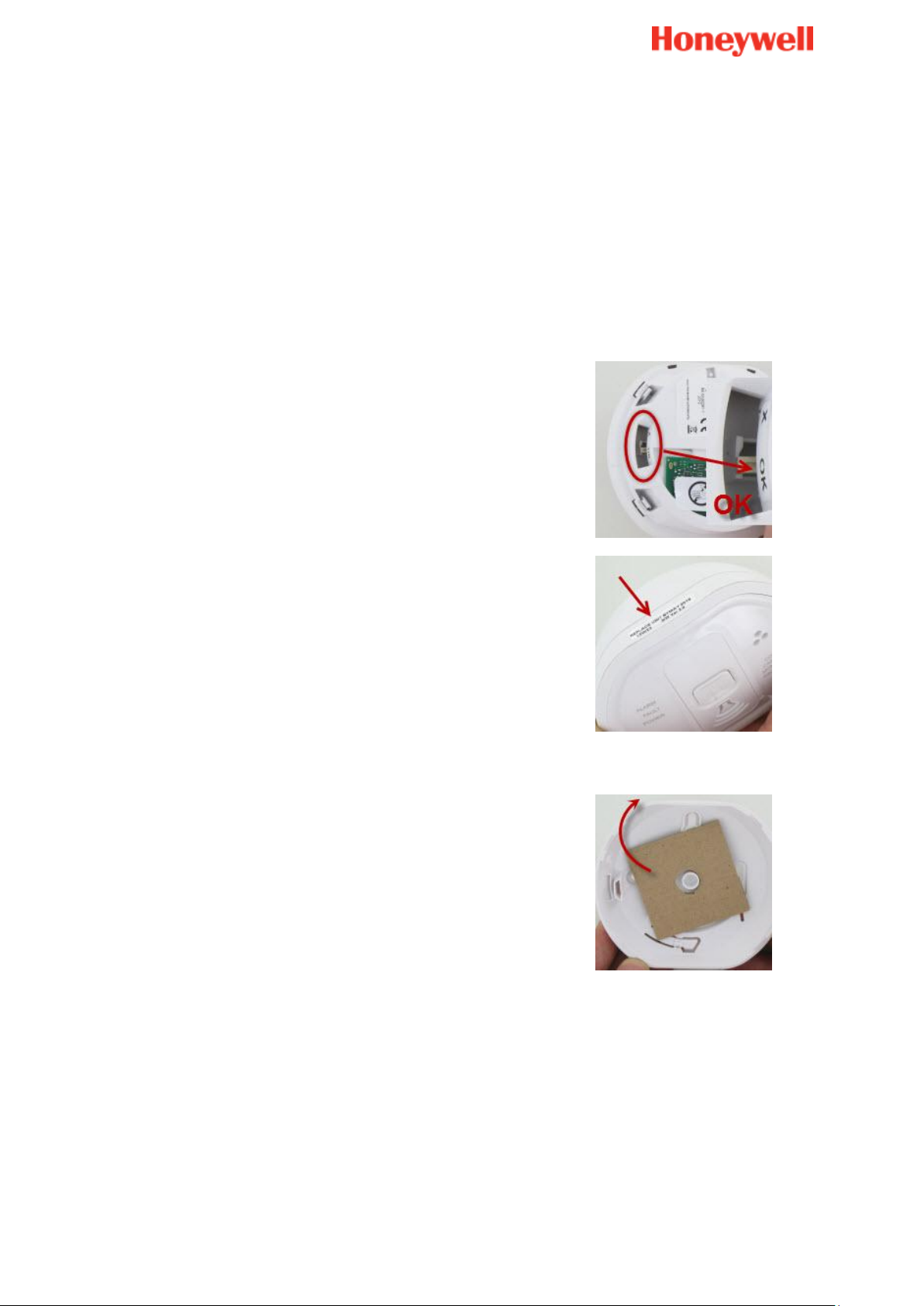
Do not mount the cover on the base when the switch
is in the X position. Ensure the switch is in the OK
position.
The CO8M batteries are not replaceable; the product
is powered for life.
When the unit has completed 6 years of operation
the amber light will flash three times every 50
seconds and beep simultaneously. This indicates
that the alarm has reached its end-of-life date and
must be replaced. This date is written on the
product.
1. Remove the mounting plate from the packaging and
the protective carton.
Every bedroom
However, if the number of carbon monoxide alarms to be fitted is limited, consider the
following points when deciding where best to fit the alarm(s):
If there is an appliance in a room where people sleep, place a CO alarm in this room
Locate an alarm in a room where the occupant(s) spend most of their time (e.g.
sitting room)
In a bedsit, place the CO alarm as far away from the cooking appliance as possible,
but near to where the person sleeps
Caution
How to install
Page 21
21
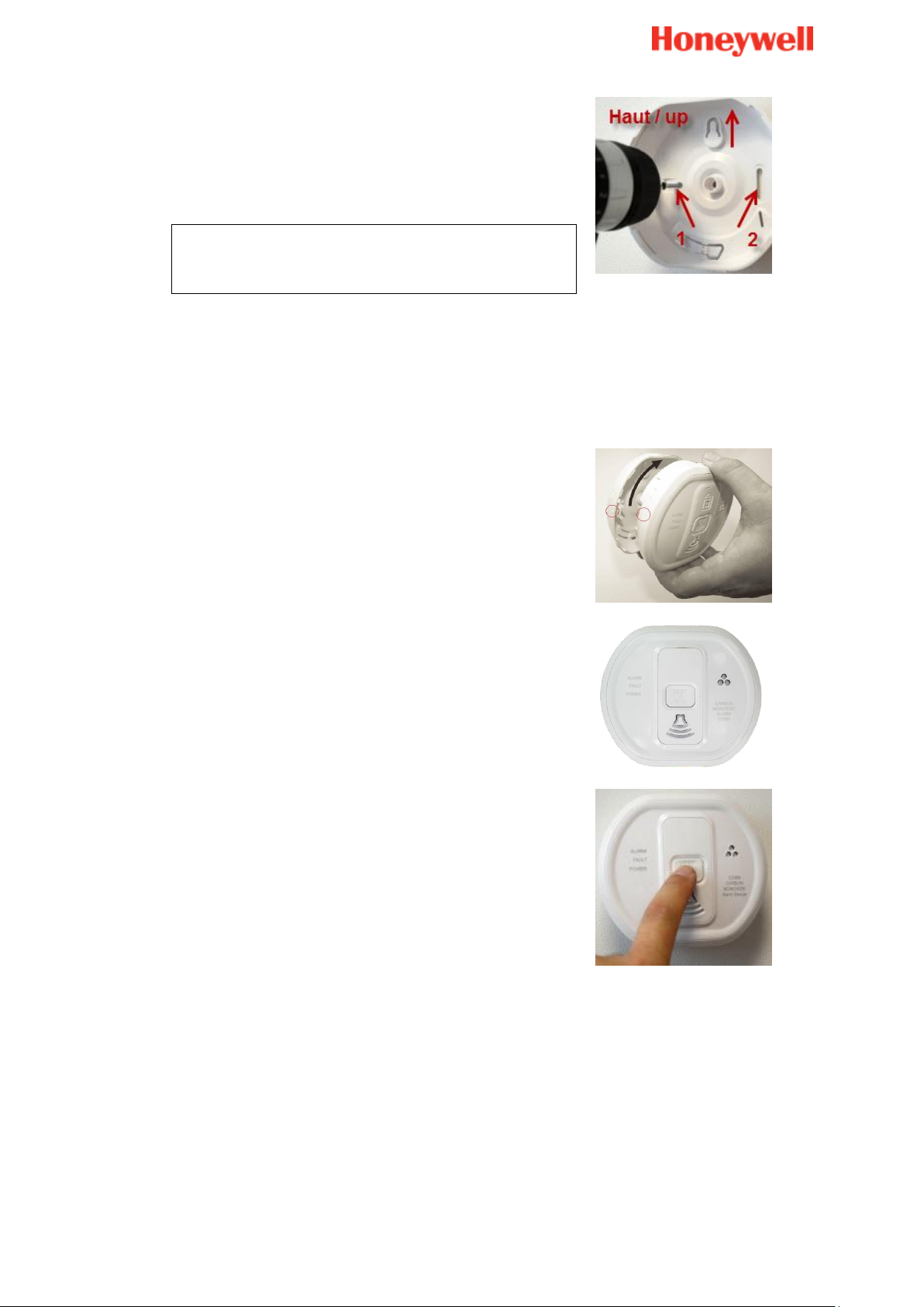
2. Place the mounting plate on the ceiling or wall
exactly where you want to mount the CO alarm. With
a pencil, mark the location of the two screw holes.
3. Drill holes using a 5.0 mm drill bit through the centre
of the marked locations.
Caution: When drilling holes, take care to avoid
any electrical wiring already present in the
ceiling or the wall.
4. Push the plastic screw anchors provided into the
drilled holes, and screw the mounting plate to the
ceiling or wall.
5. Carefully line up the CO alarm on the base, then
press and twist on.
After several seconds (up to 15 sec) two beeps will
confirm the successful enrolment.
6. Press the test button to ensure that the alarm works.
Page 22
22
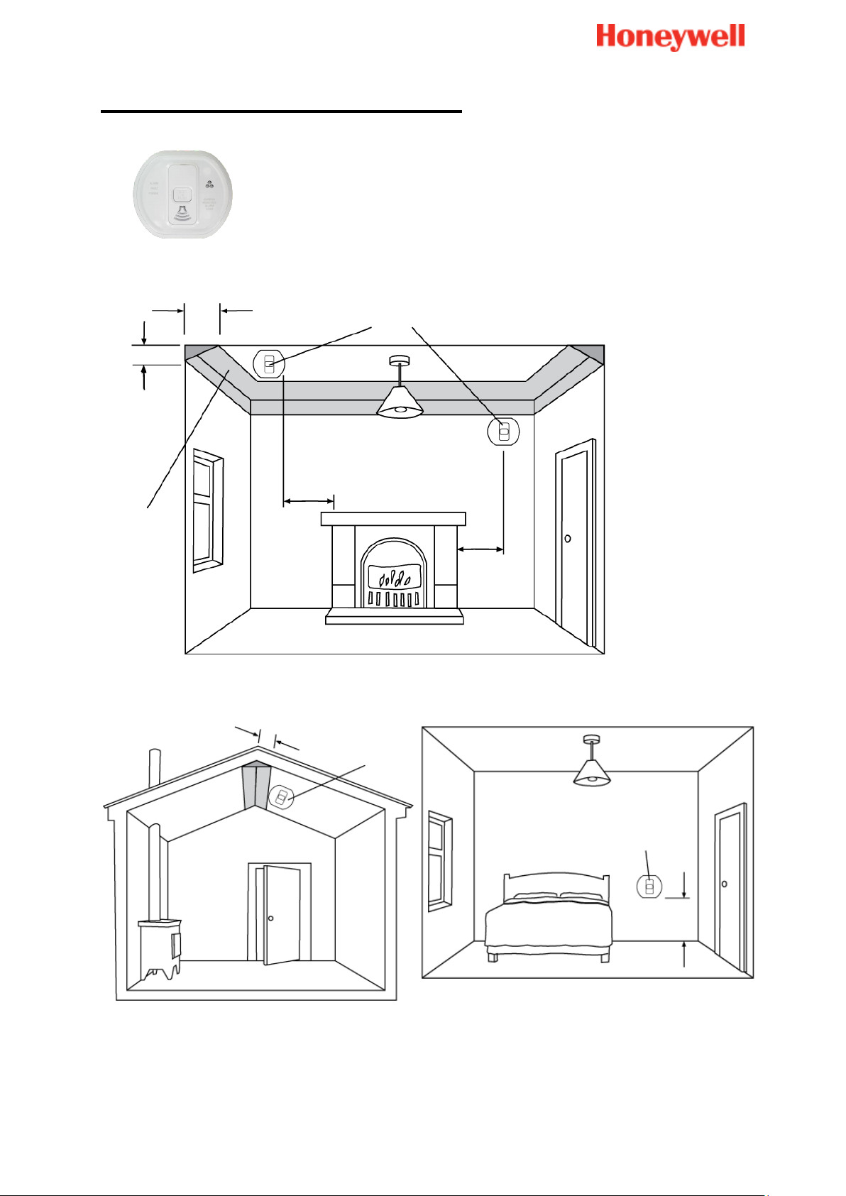
Smoke detector
Please refer to the printed manual supplied with the product for full guidance.
How to install
A help video can be found here:
http://honeywell.total-connect.eu/video/DFS8M.mp4
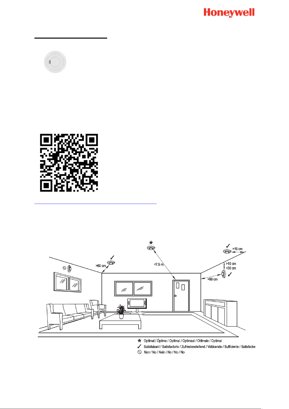
Installation requirements (DFS8M)
Smoke rises towards the ceiling, then spreads out horizontally, therefore the ideal place
to fix the sensor is in the middle of the room.
Locations to avoid:
Page 23

23
Bathrooms, kitchens, shower rooms, garages or other rooms where the smoke
sensor may be triggered by steam, condensation, normal smoke or fumes. Keep at
least 6 m away from sources of normal smoke/fumes
Locate away from very dusty or dirty areas as dust build-up in the chamber can
impair performance. It can also block the insect screen mesh and prevent smoke
from entering the smoke detector chamber
Do not locate in insect infested areas. Small insects getting into the smoke detector
chamber can cause intermittent alarms
Places where the normal temperature can exceed 40°C or is below 0°C (e.g. attics,
furnace rooms, directly above ovens or kettles etc.) as the heat/steam could cause
nuisance alarms
Near a decorative object, door, light fitting, window molding etc., that may prevent
smoke or heat from entering the sensor
Surfaces that are normally warmer or colder than the rest of the room (e.g. attic
hatches). Temperature differences might stop smoke or heat from reaching the unit
Next to, or directly above, heaters or air conditioning vents, windows, wall vents etc.
that can change the direction of airflow
In very high or awkward areas (e.g. over stairwells) where it may be difficult to reach
the alarm (for testing, hushing or battery replacement)
Locate the unit at least 1 m from dimmer controlled lights and wiring as some
dimmers can cause interference
Locate unit at least 1.5 m from fluorescent light fittings as electrical noise and/or
flickering may affect the unit
Page 24
24
Indoor siren
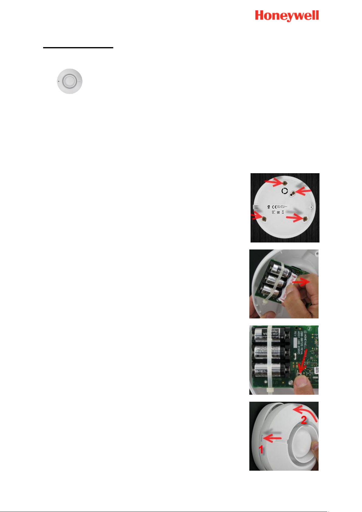
2. Position the siren base plate against the wall and mark the
3 securing holes.
3. Drill the holes, insert the screw anchors, and then screw
on the base plate.
4. Pull out the battery tab to power up the sensor.
5. Press the black button on the PCB. You will hear 2 short
beeps from the Badge reader and the siren.
6. Locate the cover onto the tab (1) on the base, and then
turn to the other side (2).
Installation requirements
Install the siren:
Away from any source of electrical interference
On a ceiling or as high as possible on a wall
Centrally, within the protected premises
How to install
1. Remove the cover.
Page 25
25
7. Fix the cover to the base with the screw provided, and
then insert the plastic protector cap.
How to replace the batteries
Average battery lifetime: 4 years
Type: CR123
Quantity: 3
1. Remove the siren cover.
WARNING: PROTECT YOUR EARS AS THE
REMAINING BATTERY POWER MAY SOUND
THE SIREN.
2. Remove the tie-wrap from the batteries.
3. Replace the batteries.
After 10 seconds you will hear short beeps.
4. Secure the cover using the screw.
Page 26

26
FAQ
How does my Le Sucre work?
Le Sucre uses wireless technology to protect the people and property in your home. This
system can be managed locally via the Badge reader or the keypad for Sucre Box. It can
also be remotely controlled via Total Connect 2.0E or the Total Connect Comfort
International application.
Several types of alerts can be sent:
An intrusion alert when the motion detector or senses something moving or when a
door contact is triggered (when your system is on)
A life safety alert when a smoke or carbon monoxide sensor(s) are triggered. These
sensors, if fitted, remains active 24 hours a day, whether the system is set or unset
Technical alerts in case of power failure or batteries being down.
I have a pet: what precautions are necessary with my motion detector?
Your detector was especially designed to be used in the presence of animals weighing
less than 30 kg. Simply make sure the animals cannot get within 1.80 m of the detector.
When to change batteries?
Check the Diagnosis page to see the battery level for each peripheral in your installation.
What maintenance of the peripherals is required?
The motion detectors require no maintenance during their lifetime apart from
replacement of the batteries about every 4 years.
How do I clean the detectors?
Remove dust with a feather duster.
Caution: Never use detergents or spray cleaners. Avoid knocking detectors,
which can cause damage.
What must I do in case of untimely alerts?
Check your installation and make sure detectors are positioned correctly. If the problem
remains, contact your installer.
Can the detectors be painted?
You must never paint or mask the front of the motion detector: this would immediately
make it unusable.
Page 27

-Français-
800-19461-B
01/2016
Le Sucre™
Guide d'utilisation
Page 28

2
Sommaire
Introduction ............................................................................... 3
Contrôle de votre système ...................................................... 4
Lecteur de badge .................................................................................................... 4
Clavier (uniquement disponible sur le Sucre Box) .............................................. 7
Télécommandes ................................................................................................... 10
Voyants du Sucre Box ......................................................................................... 12
Installation des détecteurs et sirènes .................................. 13
Contact de porte ................................................................................................... 13
Détecteurs de mouvement ................................................................................... 13
Détecteur de mouvement avec image ................................................................ 14
Détecteur de bris de vitre .................................................................................... 15
Détecteur de choc ................................................................................................ 17
Détecteur de monoxyde de carbone ................................................................... 19
Détecteur de fumée .............................................................................................. 22
Sirène d'intérieur .................................................................................................. 24
FAQ .......................................................................................... 26
Page 29

Introduction
Ce document a pour but de vous aider à installer et à utiliser votre système Le Sucre.
Ce système est constitué de trois types de composants :
L'unité centrale Le Sucre, qui constitue la pièce centrale du système : elle
communique avec tous les autres composants du système et transmet les alarmes
en cas de problème.
Des équipements de contrôle et d'indication permettent d'utiliser le système
(par exemple, de l'armer ou le désarmer).
Des détecteurs installés dans les locaux communiquent avec l'unité centrale en
cas de problème (intrusion, incendie, etc.). Des sirènes retentissent localement
lorsqu'une alarme se déclenche.
3
Page 30
4
Contrôle de votre système
Lecteur de badge
Le lecteur de badge possède une sirène intégrée qui retentira en cas d'alarme.
Conditions d'installation
Installez le lecteur de badge :
près de la porte généralement utilisée pour entrer dans le logement ;
en laissant un dégagement d'au moins 30 cm autour de l'appareil ;
à environ 1,50 m du sol (pour une personne d'une taille de 1,70 m à 1,80 m) ;
sur un mur.
N'installez pas le lecteur de badge :
en extérieur ;
près d'une source de chaleur (par exemple, cheminée, radiateur, convecteur, four,
plaques de cuisson) ;
près d'une arrivée d'eau (par exemple, salle de bains).
Procédure d'installation
Vous trouverez une vidéo d’aide ici :
http://honeywell.total-connect.eu/video/SPR-S8EZ.mp4
Utilisation du lecteur de badge
Il est possible de définir le système dans deux modes différents :
- Armement total : appliquez ce mode lorsque vous quittez les locaux.
- Armement partiel : appliquez ce mode lorsque vous voulez utiliser votre système
quand vous êtes dans les locaux (la nuit par exemple). Dans ce cas, les détecteurs
de mouvement ne sont pas actifs, et seuls les contacts de porte sont opérationnels
(ou bien les détecteurs que vous avez réglés sur « mode nuit »)
Page 31

Pour définir le système lorsque vous quittez les locaux sur le mode :
1. Appuyez sur ce bouton.
2. Présentez votre badge devant cette zone du lecteur de badge.
3. Le voyant vert clignote pendant la durée du délai de sortie.
4. Quittez les locaux avant la fin des signaux sonores
(dont le rythme s'accélère en fin de délai).
1. Appuyez sur ce bouton.
2. Présentez votre badge devant cette zone du lecteur
de badge.
3. Le voyant vert clignote pendant la durée du délai de sortie
et continue à clignoter.
1. Le voyant vert est allumé (fixe ou clignotant).
2. Présentez votre badge devant cette zone du lecteur de badge.
3. Le voyant vert s'éteint.
Armement total
Pour définir le système lorsque vous êtes encore dans les locaux sur
le mode : Armement partiel
Mise hors service du système
5
Page 32

6
État en service/hors service (vert) :
Clignotement rapide pendant le délai d'entrée/sortie
Clignotement lent lorsque le système est réglé sur le mode
Armement partiel
Éteint lorsque le système est désactivé et après expiration du délai
de sortie
État en cas de défaut (rouge) :
Allumé lorsqu'un défaut est présent (voir détails sur le
serveur Web)
Clignotement lent lorsque la charge des piles du lecteur de
badge est faible
Éteint en situation normale
État d'intrusion (orange) :
Allumé lorsqu'une alarme anti-intrusion se déclenche alors que
le système est activé
Sera réinitialisé lors de la prochaine action d'activation
État technique (orange) :
Allumé lorsqu'une alarme de détection de fumée s'est déclenchée
Clignotement rapide en cas de déclenchement d'autres alarmes
(voir détails sur le serveur Web)
Le lecteur de badge s'allume.
Page 33

Clavier (uniquement disponible sur le Sucre
Box)
Le clavier comporte une sirène intégrée qui retentit en cas d’alarme.
Conditions d’installation
Installez le clavier :
près de la porte généralement utilisée pour entrer dans le logement ;
en laissant un dégagement d'au moins 30 cm autour de l'appareil ;
à environ 1,50 m du sol (pour une personne d'une taille de 1,70 m à 1,80 m) ;
sur un mur.
N'installez pas le clavier :
en extérieur ;
près d'une source de chaleur (par exemple, cheminée, radiateur, convecteur, four,
plaques de cuisson) ;
près d'une arrivée d'eau (par exemple, salle de bains).
Procédure d’installation
Vous trouverez une vidéo d’aide ici :
http://honeywell.total-connect.eu/video/SPR-S8EZ.mp4
Utilisation et programmation du clavier
La section suivante explique comment installer et utiliser votre clavier sans fil. Le clavier sert
à armer et à désarmer votre système de sécurité à l’aide d’un code d’accès valide ou d’un
badge.
La première étape consiste à enregistrer votre clavier et les badges sur le système via le
portail Web, comme pour tous les autres périphériques.
Si vous souhaitez utiliser des codes pour armer et désarmer votre système, vous devrez
programmer le clavier. Veuillez-vous reporter au manuel que vous pouvez télécharger ici :
http://www.honeywell.com/security/emea/hscdownload
7
Page 34

8
Sortie de sirène
Défaillance
système (*) (DEL 3)
Alarme
technique
Touches S.O.S
DEL Système
armé (DEL 1)
Alarme antiintrusion (*)
(DEL 2)
Touche
d’armement total
Touche
d’armement partiel
Emplacement du
lecteur de badges
CLAVIER
Le clavier est équipé d’un lecteur de badges de proximité, se trouvant à côté du symbole
; le clavier comporte également une sirène intégrée ayant un effet dissuasif
et 4 voyants DEL qui vous informent de l’état du système.
Armement à l’aide de votre code ou de votre badge
Appuyez sur une touche d’armement et saisissez le code ou présentez un badge
enregistré.
Armement total
Armement partiel
Le clavier émet la tonalité d’armement, suivie par les signaux sonores de délai de sortie.
La procédure d’armement de la zone se termine automatiquement à la fin du délai de
sortie.
Remarque :
Vérifiez toujours que votre demande d’armement total est suivie de la tonalité
d’armement.
Désarmement à l’aide de votre code ou de votre badge
Pour désarmer votre système :
Saisissez un code valide ou présentez un badge enregistré.
Page 35

La sirène du clavier émet la tonalité de désarmement.
Le désarmement du système interrompt également les sirènes si une alarme est
déclenchée.
Remarques :
Vérifiez toujours que votre demande de désarmement est suivie de la tonalité de
désarmement.
Désarmez toujours le système lorsque vous entrez à nouveau dans les locaux.
Placer le badge en face du clavier ne permet pas de modifier le statut.
9
Page 36

10
Télécommandes
En mode d’installation, appuyez simultanément sur les boutons Armement
total et Armement partiel pendant 2 secondes.
Les voyants DEL correspondants s'allument pendant 3 secondes.
Attention
Ne placez pas la télécommande dans un endroit susceptible d'être exposé à des
températures élevées
Évitez de faire tomber votre télécommande. Manipulez-la avec soin pour éviter de
l'endommager, de décharger la pile ou de provoquer des dysfonctionnements
Conservez la télécommande à l'abri de l'humidité, de la poussière et de l'eau
N'utilisez que le modèle de pile recommandé (CR2032 de Panasonic ou GP)
Procédure d'installation
Vous trouverez une vidéo d’aide ici :
http://honeywell.total-connect.eu/video/TCC800M.mp4
Pour enregistrer la télécommande :
Page 37

Le lecteur de badge émet deux signaux sonores
courts.
11
Page 38

12
Voyants du Sucre Box
Voyant 1
Voyant 2
Voyant 3
Le panneau du boîtier Sucre comporte trois voyants, illustrés ci-dessous.
- Voyant 1 : indication de l’état d’alimentation de la centrale
o Vert fixe : la centrale est correctement alimentée.
o Orange clignotant : la centrale est uniquement alimentée par la batterie.
- Voyant 2 : indication de l’état d’armement du système
o Éteint : le système est désarmé
o Vert fixe : le système est en « Armement total »
o Vert clignotant : le système est en « Armement partiel »
o Orange clignotant : une intrusion a été détectée
- Voyant 3 : indication du réseau GPRS (lors de l’installation uniquement)
o Éteint : pas de module GPRS (Sucre Box version SUE8EU-STD-E)
o Orange clignotant : réseau GPRS introuvable
o Vert fixe : réseau GPRS trouvé
Remarque : pour le Sucre Box version SUE8EU-STD-E, ce voyant est toujours
éteint car aucune carte SIM n’est utilisée
Remarque importante : lors de la première installation, le Sucre Box est
automatiquement mis à jour avec la dernière version logicielle. Cette phase dure
généralement 10 minutes, mais peut prendre jusqu’à 20 minutes. Pendant ce
temps, tous les voyants DEL sont éteints.
Page 39

Installation des détecteurs et sirènes
Remarque : lorsqu'un appareil a été correctement installé, le lecteur de badge ou le clavier
émet des signaux sonores courts
Contact de porte
Pour obtenir des instructions complètes, veuillez-vous reporter au manuel imprimé
fourni avec le produit.
Installez le contact :
dans la pièce à protéger ;
à l'opposé des charnières pour accélérer la détection à l'ouverture ;
en fixant l'aimant à la partie ouvrante, par exemple à la porte et non à
l'encadrement ;
en fixant le capteur sur l'encadrement de la porte et non sur la porte elle-même ;
avec l'aimant face à la marque indiquée sur le détecteur ;
en laissant moins de 2 cm entre l'aimant et le détecteur une fois la
porte/fenêtre fermée ;
de manière que l'ouverture en grand de la porte (ou de la fenêtre) ne risque pas
d'abîmer l'aimant ;
N'installez pas le contact :
en extérieur ;
près d'une arrivée d'eau (par exemple, salle de bains).
Détecteurs de mouvement
Pour obtenir des instructions complètes, veuillez-vous reporter au manuel imprimé
fourni avec le produit.
Installez le détecteur :
dans une zone de passage et dirigé de préférence vers une entrée (par exemple,
porte ou fenêtre) ;
si possible dans un angle pour optimiser la zone de détection ;
à un endroit dont les animaux domestiques ne risquent pas de s'approcher à
moins de 1,80 m, même en grimpant sur un meuble, des marches d'escalier,
des caisses, etc. ;
dans une zone de détection libre de tout obstacle (par exemple, rideaux, armoires) ;
à une hauteur comprise entre 2,30 m et 2,50 m au-dessus du sol.
N'installez pas le détecteur :
13
Page 40

14
dans une pièce plus petite que la zone de détection (au moins 4 m²) ;
en extérieur ;
près d'une source de chaleur (par exemple, cheminée, radiateur, convecteur, four,
plaques de cuisson) ;
près d'une source d'air froid (par exemple, climatiseur) ;
en face d'une fenêtre ;
près d'une arrivée d'eau (par exemple, salle de bains).
Ne pas peindre le détecteur
Détecteur de mouvement avec image
Pour obtenir des instructions complètes, veuillez-vous reporter au manuel imprimé
fourni avec le produit.
Installez le détecteur :
dans une zone de passage et dirigé de préférence vers une entrée (par exemple,
porte ou fenêtre) ;
si possible dans un angle pour optimiser la zone de détection ;
à un endroit dont les animaux domestiques ne risquent pas de s'approcher
à moins de 1,80 m, même en grimpant sur un meuble, des marches d'escalier,
des caisses, etc. ;
dans une zone de détection libre de tout obstacle (par exemple, rideaux, armoires) ;
à une hauteur comprise entre 2,30 m et 2,50 m au-dessus du sol.
N'installez pas le détecteur :
dans une pièce plus petite que la zone de détection (au moins 4 m²) ;
en extérieur ;
près d'une source de chaleur (par exemple, cheminée, radiateur, convecteur, four,
plaques de cuisson) ;
près d'une source d'air froid (par exemple, climatiseur) ;
en face d'une fenêtre ;
près d'une arrivée d'eau (par exemple, salle de bains).
Ne pas peindre le détecteur
Page 41

Détecteur de bris de vitre
1. Ouvrez le détecteur.
2. Vissez la base sur le mur.
3. Maintenez les piles en place et retirez la languette
des piles pour alimenter le détecteur.
Conditions d'installation
Montez le détecteur entre la vitre à protéger et les éventuels dispositifs lourds venant
recouvrir la fenêtre. En cas de présence de tels dispositifs, le détecteur peut être monté
sur le cadre de la fenêtre.
Ne pas monter le détecteur :
sur des poteaux ou des piliers ;
dans des pièces contenant du matériel bruyant (compresseurs à air, outils
électriques, etc.) si ce matériel est en fonctionnement lorsque le détecteur est armé ;
à des endroits où la visibilité de la vitre par le détecteur peut être obstruée
volontairement.
Procédure d'installation
1. Orientez le microphone de façon à avoir une vue la plus directe possible sur la vitre
à protéger. En cas de montage au plafond, l'extrémité porteuse du microphone doit
se trouver face à la vitre à protéger.
15
Page 42

16
4. Refermez le détecteur.
Remplacement des piles
Durée de vie moyenne des piles : 4 ans
Type : CR123A
Quantité : 2
1. Ouvrez le détecteur.
2. Remplacez les piles (type CR123).
3. Refermez le détecteur.
Page 43

Détecteur de choc
1. Retirez le couvercle du détecteur.
2. Montez le détecteur sur une surface pleine à l'aide
des vis fournies. L'appareil possède deux trous de
montage.
3. Pour le SHKC8M uniquement, montez l'aimant
(fourni) à proximité de la bande d'alignement du
détecteur.
Conditions d'installation
Le détecteur de chocs de la série SHK(C)8M est conçu pour protéger les entourages
de portes et de fenêtres et permet de détecter les tentatives d’effraction.
Il est capable de détecter deux types de tentatives d'effraction :
Attaque violente : le dispositif déclenchera une alarme pour chaque choc dont
l'intensité excède le niveau de sensibilité à une attaque violente, réglé en usine ;
Attaques répétées : le dispositif déclenchera une alarme après un nombre défini
(contrôlable) de chocs consécutifs dont l'intensité excède le niveau de sensibilité
à des attaques répétées, réglé en usine, sur une période de 8 s.
Procédure d'installation
17
Page 44

18
4. Réinstallez le couvercle.
Remplacement des piles
Durée de vie moyenne des piles : 4 ans
Type : CR123A
Quantité : 1
1. Retirez le couvercle.
2. Remplacez la pile.
3. Réinstallez le couvercle.
Page 45

Détecteur de monoxyde de carbone
Alarme d'OC
300 mm
150 mm
AIR
STAGNANT
NE PAS
PLACER ICI
1 à 3 m
1 à 3 m
Alarme
d'OC
Alarme d'OC
Environ
1 à 2 m
300 mm
Conditions d'installation
Où placer le détecteur de monoxyde de carbone :
Dans l'idéal, une alarme de détection de monoxyde de carbone doit être installée :
dans chaque pièce renfermant des appareils de combustion ;
19
Page 46

20
dans les pièces éloignées fréquemment occupées par les habitants ;
Ne montez pas le couvercle sur la base lorsque le
commutateur se trouve dans la position X. Vérifiez
que le commutateur se trouve dans la position OK.
Les piles du CO8M ne se remplacent pas. L'appareil
est alimenté pour toute sa durée de vie.
Au bout de 6 ans, le voyant orange clignotera deux
fois toutes les 50 secondes et émettra
simultanément un signal sonore. Cela indique que
l'alarme est en fin de vie et qu'elle doit être
remplacée. Cette date est inscrite sur l'appareil.
1. Retirez la plaque de montage de l'emballage, ainsi
que le carton de protection.
dans chaque chambre à coucher.
Toutefois, si le nombre d'alarmes de monoxyde de carbone à installer est limité, les
points suivants doivent être pris en considération pour déterminer le meilleur endroit
pour leur installation.
Si un appareil à combustion est présent dans une pièce où des gens dorment,
installez un détecteur de CO dans cette pièce.
Installez une alarme dans les pièces où les habitants passent le plus de temps
(par ex. le salon).
Dans une chambre meublée, l'alarme de CO doit être installée le plus loin possible
des appareils de cuisson, mais près de l’endroit où la personne dort.
Attention
Procédure d'installation
Page 47

2. Placez la plaque de montage sur le plafond ou le
mur, à l'endroit précis où vous souhaitez installer
l'alarme de CO. Avec un crayon, marquez
l'emplacement des trous des deux vis.
3. À l'aide d'un foret de 5,0 mm, percez des trous au
centre des emplacements marqués.
Attention : en perçant les trous, veillez à ne pas
toucher d'éventuels fils électriques présents
dans le plafond ou les murs.
4. Enfoncez les chevilles en plastique fournies dans les
trous que vous avez percés et vissez la plaque de
montage au plafond ou au mur.
5. Alignez soigneusement l'alarme de CO sur la base,
puis appuyez et tournez.
Au bout de quelques secondes (jusqu'à 15 s), deux
signaux sonores confirmeront que l'appareil a bien
été enregistré.
6. Appuyez sur le bouton de test pour vérifier que
l'alarme fonctionne.
21
Page 48

22
Détecteur de fumée
Pour obtenir des instructions complètes, veuillez-vous reporter au manuel imprimé
fourni avec le produit.
Procédure d’installation
Vous trouverez une vidéo d’aide ici :
http://honeywell.total-connect.eu/video/DFS8M.mp4
Conditions d'installation (DFS8M)
La fumée s'élève généralement vers le plafond, puis se diffuse horizontalement.
Le meilleur endroit pour placer le détecteur est donc au centre de la pièce.
Page 49

Lieux à éviter :
Salles de bain, cuisines, douches, garages ou autres pièces où le détecteur de
fumée risquerait de se déclencher du fait de la vapeur, condensation, des émissions
de fumée ou des émanations normales. Veillez à installer le dispositif à plus de 6 m
des sources d'émissions de fumées/d'émanations normales.
Éloignez le détecteur des zones très poussiéreuses ou sales, car un dépôt de
poussière dans la chambre risque de nuire aux performances. Il risque également
d'obstruer les mailles de l'écran anti-insectes et d'empêcher la fumée de pénétrer
dans la chambre du détecteur de fumée.
N'installez pas le dispositif dans des zones infestées d'insectes. Si de petits insectes
pénètrent dans la chambre du détecteur de fumée, ils risquent de déclencher des
alarmes intermittentes.
Endroits où la température normale peut dépasser 40 °C ou descendre au-dessous
de 0 °C (c.-à-d. combles, chaufferies, à l'aplomb de fours ou bouilloires, etc.) car la
chaleur/vapeur peut provoquer des déclenchements d'alarmes intempestifs.
À proximité d'éléments de décor, de portes, d'encastrements d'éclairage, de
moulures de fenêtres, etc., qui peuvent empêcher la fumée ou la chaleur
d'atteindre l'alarme.
Surfaces généralement plus froides ou chaudes que le reste de la pièce (ex.,
trappes de grenier). Les différences de températures peuvent empêcher la fumée
ou la chaleur d'atteindre le dispositif.
À proximité ou à l'aplomb de chauffages ou de grilles de climatisation, fenêtres,
bouches d'aération murales, etc. susceptibles de faire varier la direction du flux d'air.
Dans des zones très élevées, ou difficiles d'accès (ex, plafonds de cages d'escalier)
où vous aurez des difficultés pour atteindre l'alarme (pour la tester, l'éteindre ou
remplacer la pile).
Placez le dispositif à plus d'1 m des éclairages à commande d'intensité et de leur
câblage, en raison des risques d'interférences.
Placez le dispositif à plus d'1,5 m des encastrements d'éclairage fluorescent car les
« parasites » d'origine électrique et/ou
leur clignotement risque d'affecter le fonctionnement du dispositif.
23
Page 50

24
Sirène d'intérieur
2. Placez la plaque de base de la sirène contre le mur et
marquez l'emplacement des 3 trous de fixation.
3. Percez les trous, enfoncez les chevilles, puis vissez
la plaque de base.
4. Retirez la languette des piles pour alimenter le détecteur.
5. Appuyez sur le bouton noir de la carte de circuit imprimé.
Le lecteur de badge et la sirène émettent 2 signaux
sonores courts.
6. Placez le couvercle sur la languette (1) de la base, puis
tournez dans l'autre sens (2).
Conditions d'installation
Installez la sirène :
loin de toute source d'interférences électriques ;
au plafond ou aussi haut que possible sur un mur ;
au centre des locaux à protéger.
Procédure d'installation
1. Retirez le couvercle.
Page 51

7. Fixez le couvercle à la base à l'aide de la vis fournie, puis
enfoncez le capuchon de protection en plastique.
Remplacement des piles
Durée de vie moyenne des piles : 4 ans
Type : CR123
Quantité : 3
1. Retirez le couvercle de la sirène.
AVERTISSEMENT : PROTEGEZ VOS
OREILLES CAR L'ENERGIE RESTANT DANS
LES PILES PEUT DECLENCHER LA SIRENE.
2. Retirez le collier de serrage des piles.
3. Remplacez les piles.
Au bout de 10 secondes, vous entendrez de brefs
signaux sonores.
4. Fixez le couvercle à l'aide de la vis.
25
Page 52

26
FAQ
Comment fonctionne Le Sucre ?
Le Sucre utilise une technologie sans fil pour protéger les personnes et les biens
dans votre logement. Ce système peut être géré en local grâce au lecteur de badge
ou au clavier pour le boîtier Sucre. Il peut également être contrôlé à distance via Total
Connect 2.0E ou l’application Total Connect Comfort International (dans le cas de Sucre
Box).
Il peut transmettre plusieurs types d'alertes :
Une alerte d'intrusion lorsque le détecteur de mouvement détecte que quelque
chose a bougé ou quand un contact de porte se déclenche (lorsque votre système
est activé) ;
Une alerte de protection vitale lorsqu'un détecteur de fumée ou de monoxyde de
carbone se déclenche. Ces détecteurs, si vous en installez, restent actifs 24/24 h,
que le système soit activé ou désactivé ;
Des alertes techniques en cas de panne de courant ou de déchargement des
batteries.
J'ai des animaux domestiques : quelles précautions dois-je prendre avec
mon détecteur de mouvement ?
Votre détecteur est spécialement conçu pour fonctionner en présence d'animaux pesant
moins de 30 kg. Il suffit de vous assurer que ces derniers ne peuvent pas s'en approcher
à moins de 1,80 m.
Quand remplacer les piles ?
Consultez la page Diagnostic pour connaître le niveau des piles de chaque périphérique
de votre installation.
De quel entretien les périphériques ont-ils besoin ?
Les détecteurs de mouvement ne nécessitent aucun entretien pendant toute leur durée
de vie. Seules les piles doivent être remplacées tous les 4 ans environ.
Comment nettoyer les détecteurs ?
Retirez la poussière à l'aide d'un plumeau.
Attention : n'utilisez jamais de détergents ou de nettoyant aérosol. Évitez de
heurter les détecteurs, ce qui pourrait les endommager.
Que dois-je faire en cas d'alerte inopportune ?
Vérifiez votre installation et assurez-vous que les détecteurs sont correctement
positionnés. Si le problème persiste, contactez votre installateur.
Est-il possible de peindre les détecteurs ?
La façade d'un détecteur de mouvement ne doit jamais être peinte ou masquée : cela le
rendrait immédiatement inutilisable.
Page 53

-Español-
Le Sucre™
Guía del usuario
800-19461-B
01/2016
Page 54

2
Contenido
Introducción ..............................................................................3
Control del sistema ..................................................................4
Lector de identificaciones .................................................................................... 4
Teclado (disponible solo en Sucre Box) ............................................................. 7
Mandos ................................................................................................................. 10
Indicación luminosa de Sucre Box .................................................................... 12
Instalación de detectores y sirenas ......................................13
Contacto de puerta .............................................................................................. 13
Detectores de movimiento ................................................................................. 13
Detector de movimiento con imagen ................................................................. 14
Detector de ruptura de cristales ........................................................................ 15
Sensor de impactos ............................................................................................ 17
Detector de monóxido de carbono .................................................................... 19
Detector de humo ................................................................................................ 22
Sirena interior ...................................................................................................... 24
Preguntas frecuentes .............................................................26
Page 55

3
Introducción
El propósito de este documento es ayudarle con la instalación y la operación del sistema
Le Sucre.
El sistema comprende tres tipos de componentes:
Unidad central Le Sucre, que es el centro del sistema: se comunica con todos los
demás componentes del sistema y transmite las alarmas en caso de problemas.
Equipos de control e indicación, que permiten utilizar el sistema (activarlo y
desactivarlo, por ejemplo).
Detectores, que se instalan en las instalaciones y se comunican con la unidad
central en caso de problemas (intrusión, incendio, etc). Sirenas, que suenan
localmente cuando se produce una alarma.
Page 56

4
Control del sistema
Lector de identificaciones
El Lector de identificadores incluye una sirena integrada que suena en caso
de alarma.
Requisitos de instalación
Instale el Lector de identificadores:
Cerca de la puerta que se utilice habitualmente para entrar en la casa
Con al menos 30 cm de espacio libre alrededor de él
A 1,50 m de distancia de la puerta, aproximadamente (para una persona
de 1,70 a 1,80 m de altura)
En una pared
No instale el Lector de identificadores:
En el exterior
Cerca de una fuente de calor (por ejemplo una chimenea, un radiador,
un convector, un horno, un hornillo)
Cerca de un punto de agua (por ejemplo, un aseo)
Cómo realizar la instalación
Puede encontrar un vídeo de ayuda aquí:
http://honeywell.total-connect.eu/video/SPR-S8EZ.mp4
Cómo usar el Lector de identificadores
El sistema se puede armar en dos modos diferentes:
- Activación total/armado total: este modo se utiliza cuando se sale
de las instalaciones.
- Activación parcial/armado parcial: este modo se utiliza cuando se desea usar el
sistema permaneciendo en las instalaciones (por ejemplo, de noche). En este caso,
los detectores de movimiento no están activos y solo están operativos los contactos
de las puertas (o los detectores ajustados en “modo noche”).
Page 57

5
1. Pulse este botón.
2. Presente el mando frente a esta área en el Lector de
identificadores.
3. La luz verde parpadea durante el retardo de salida.
4. Salga de las instalaciones antes del final de los pitidos
(más rápidos al final).
1. Pulse este botón.
2. Presente el mando frente a esta área en el Lector
de identificadores.
3. La luz verde parpadea durante el retardo de salida
y continúa parpadeando.
1. La luz verde está activada (iluminada o parpadeando).
2. Presente el identificador frente a esta área en el Lector
de identificadores.
3. La luz verde se desactiva.
Para armar el sistema al salir de las instalaciones: Activación total
Para armar el sistema permaneciendo en las instalaciones:
Activación parcial
Para desarmar el sistema
Page 58

6
Estado de armado/desarmado (verde):
Parpadeo rápido durante el retardo de entrada/salida
Parpadeo lento cuando el sistema está en modo de activación
parcial
Apagada cuando el sistema está desarmado y después del retardo
de salida
Estado de valores predeterminados (rojo):
Encendida cuando hay un estado predeterminado presente
(detallado en el servidor web)
Parpadeo lento si la batería del Lector de identificadores está baja
Apagada en una situación normal
Estado de intrusión (naranja):
Encendida cuando se ha producido una alarma de intruso cuando
estaba armado el sistema
Se restablecerá en la siguiente acción de armado
Estado técnico (naranja):
Encendida cuando se produce una alarma de detección de humos
Parpadeo rápido para otras alarmas (detallado en el servidor web)
Luces del Lector de identificadores
Page 59

7
Teclado (disponible solo en Sucre Box)
El Teclado incluye una sirena integrada que suena en caso de alarma.
Requisitos de instalación
Instale el Teclado:
Cerca de la puerta que se utilice habitualmente para entrar en la casa
Con al menos 30 cm de espacio libre alrededor de él
A 1,50 m de distancia de la puerta, aproximadamente (para una persona
de 1,70 a 1,80 m de altura)
En una pared
No instale el Teclado:
En el exterior
Cerca de una fuente de calor (por ejemplo una chimenea, un radiador,
un convector, un horno, un hornillo)
Cerca de un punto de agua (por ejemplo, un aseo)
Cómo realizar la instalación
Puede encontrar un vídeo de ayuda aquí:
http://honeywell.total-connect.eu/video/GKP-S8M.mp4
Cómo usar y programar el teclado
En la siguiente sección se describe como instalar y utilizar el teclado inalámbrico. El teclado
se utiliza para armar y desarmar el sistema de seguridad utilizando un código de acceso
válido o un TAG de tecla.
El primer paso es registrar el teclado y las etiquetas en el sistema a través del portal web
como el resto de los dispositivos.
Si desea utilizar códigos para armar y desarmar el sistema deberá programar el teclado.
Consulte el manual impreso que puede descargar aquí:
http://www.honeywell.com/security/emea/hscdownload
Page 60

8
Arma el conjunto total
Arma el conjunto parcial
El teclado está equipado con un lector de proximidad de etiquetas situado junto al símbolo
; el teclado también dispone de una sirena integrada como medio disuasorio y 4 LEDs
para informar del estado del sistema.
Armado usando su código o etiqueta
Pulse una tecla de armado en el teclado e introduzca el código o presente una TAG
registrada.
El teclado emite el tono de armado seguido de los pitidos de retardo para salida.
El armado de la zona se completa automáticamente al final del retardo de salida.
Nota:
Asegúrese siempre de que la solicitud de armado total va seguida del tono de armado.
Desarmado usando su código o etiqueta
Para desarmar su sistema:
Introduzca un código válido o presente una TAG registrada.
Page 61

9
Notas:
El tono de desarmado lo emite la sirena del teclado.
Al desarmar el sistema también se detienen las sirenas si se ha activado una
alarma.
Asegúrese siempre de que la solicitud de desarmado va seguida del tono de
desarmado.
Desarme siempre el sistema al volver a entrar al lugar.
Sostener la TAG frente al teclado no revierte el estado.
Page 62

10
Mandos
Pulse simultáneamente los botones 1 y 3 durante menos de 2 segundos.
Los LED correspondientes se iluminarán durante 3 segundos.
Precaución
No ponga el mando en una ubicación donde pueda estar sometido a altas
temperaturas
Tenga cuidado para no dejar caer el mando. Manéjelo con cuidado. De lo contrario,
puede dañarlo, descargar la batería o provocar una avería
Mantenga el mando alejado de la humedad, el polvo y el agua
Utilice solo la batería recomendada (CR2032 de Panasonic o GP)
Cómo realizar la instalación
Puede encontrar un vídeo de ayuda aquí:
http://honeywell.total-connect.eu/video/TCC800M.mp4
Para registrar el mando:
Page 63

11
Oirá 2 pitidos cortos del Lector de
identificadores.
Page 64

12
Indicación luminosa de Sucre Box
Luz 1
Luz 2
Luz 3
El panel de Sucre Box tiene tres luces, como se muestra a continuación.
- Luz 1: Indicación de estado de alimentación eléctrica del panel
o Verde fija: el panel se alimenta correctamente.
o Naranja intermitente: el panel se alimenta solo con batería.
- Luz 2: Indicación del estado de armado del sistema
o Apagada: El sistema está desarmado
o Verde fija: el sistema está en “armado total”
o Verde intermitente: el sistema está en “armado parcial”
o Naranja intermitente: se ha detectado una intrusión
- Luz 3: Indicación de la red GPRS (solo en la instalación)
o Apagada: sin módulo GPRS (Sucre Box versión SUE8EU-STD-E)
o Naranja intermitente: red GPRS no hallada
o Verde fija: red GPRS hallada
Nota: Con Sucre Box versión SUE8EU-STD-E, la luz siempre debe estar
apagada porque no se utiliza tarjeta SIM
Nota importante: En la primera instalación, Sucre Box se actualiza
automáticamente con la última versión del firmware. Esta fase suele durar 10 min,
pero puede tardar hasta 20 min. Durante este tiempo, todos los LEDs se apagan.
Page 65

13
Instalación de detectores y sirenas
Nota: después de instalar correctamente un dispositivo, oirá pitidos cortos del Lector de
identificadores o del teclado.
Contacto de puerta
Consulte el manual impreso suministrado con el producto para instrucciones
completas.
Instale el contacto:
Dentro de la habitación que vaya a proteger
En el lado opuesto a las bisagras, para detectar con mayor rapidez la apertura
Monte el imán en la parte que se abre, por ejemplo en la puerta y no en el marco
Monte el sensor en el marco de la puerta y no en la puerta
Con el imán en el lado opuesto a la marca que se muestra en el detector
Con menos de 2 cm entre el imán y el detector cuando la puerta
o la ventana esté cerrada
De modo que la puerta o la ventana no dañe de ninguna manera el imán
No instale el contacto:
En el exterior
Cerca de un punto de agua (por ejemplo, un aseo)
Detectores de movimiento
Consulte el manual impreso suministrado con el producto para instrucciones completas.
Instale el detector:
En un área de circulación, apuntando preferiblemente hacia las entradas
(por ejemplo, la puerta o la ventana)
Preferiblemente en una esquina, para optimizar el área de detección
En un lugar donde los animales no puedan acercarse a una distancia de 1,80 m
subiéndose a los muebles, a escaleras, cajas o a cualquier otro objeto
En un área de detección libre de obstáculos (por ejemplo cortinas, armarios)
A una altura de entre 2,30 m y 2,50 m sobre el suelo
Page 66

14
No instale el detector:
En una habitación menor que el área de detección (al menos 4 m²)
En el exterior
Cerca de una fuente de calor (por ejemplo una chimenea, un radiador,
un convector, un horno, un hornillo)
Cerca de una fuente de aire frío (por ejemplo, aire acondicionado)
Frente a una ventana
Cerca de un punto de agua (por ejemplo, un aseo)
No pinte el detector
Detector de movimiento con imagen
Consulte el manual impreso suministrado con el producto para instrucciones
completas.
Instale el detector:
En un área de circulación, apuntando preferiblemente hacia las entradas
(por ejemplo, la puerta o la ventana)
Preferiblemente en una esquina, para optimizar el área de detección
En un lugar donde los animales no puedan acercarse a una distancia de 1,80 m
subiéndose a los muebles, a escaleras, cajas o a cualquier otro objeto
En un área de detección libre de obstáculos (por ejemplo cortinas, armarios)
A una altura de entre 2,30 m y 2,50 m sobre el suelo
No instale el detector:
En una habitación menor que el área de detección (al menos 4 m²)
En el exterior
Cerca de una fuente de calor (por ejemplo una chimenea, un radiador,
un convector, un horno, un hornillo)
Cerca de una fuente de aire frío (por ejemplo, aire acondicionado)
Frente a una ventana
Cerca de un punto de agua (por ejemplo, un aseo)
No pinte el detector
Page 67

15
1. Abra el sensor.
2. Atornille la base a la pared.
3. Mantenga las pilas colocadas y tire de la lengüeta
de las pilas para conectar el sensor.
Detector de rotura de cristales
Requisitos de instalación
Monte el detector entre el cristal protegido y las cubiertas pesadas que pueda haber en
la ventana. Cuando haya cubiertas de ventana presentes, el detector puede montarse
en el marco de la ventana.
No monte el detector:
En postes o pilares
En habitaciones con equipos ruidosos (compresores de aire, herramientas
eléctricas, etc.), si este equipo se utiliza cuando esté activado el detector
Donde la visión del cristal desde el detector pueda obstruirse intencionadamente
Cómo realizar la instalación
Oriente el micrófono para obtener la mejor línea de visión del cristal protegido.
Si se monta en el techo, el extremo del micrófono debe orientase hacia el cristal
protegido.
Page 68

16
4. Cierre el sensor.
Cómo cambiar las baterías
Vida media de la batería: 4 años
Tipo: CR123A
Cantidad: 2
1. Abra el sensor.
2. Cambie las baterías (de tipo CR123).
3. Cierre el sensor.
Page 69

17
1. Retire la tapa del sensor.
2. Monte el sensor sobre una superficie sólida con los
tornillos suministrados. Hay dos orificios de montaje.
3. Solo para SHKC8M, monte el imán (suministrado)
junto a la tira de alineación del sensor.
Sensor de impactos
Requisitos de instalación
La serie SHK(C)8M se ha diseñado para proteger los alrededores de puertas y ventanas
y se utiliza para detectar cualquier ataque por la fuerza sobre la superficie en la que esté
instalado.
Es capaz de detectar dos tipos diferentes de ataque por la fuerza:
Ataque fuerte: el dispositivo enviará una alarma por cualquier evento de impacto
único cuya intensidad supere el nivel de sensibilidad de ataque fuerte establecido
en fábrica
Ataques repetidos: el dispositivo enviará una alarma después de un número
definido (controlable) de impactos consecutivos cuya intensidad supere el nivel
de sensibilidad de ataque repetido establecido en fábrica en un período de 8 s
Cómo realizar la instalación
Page 70

18
4. Vuelva a colocar la tapa.
Cómo cambiar las baterías
Vida media de la batería: 4 años
Tipo: CR123A
Cantidad: 1
1. Retire la tapa.
2. Vuelva a colocar la batería.
3. Vuelva a colocar la tapa.
Page 71

19
Alarma de CO
300 mm
150 mm
Aire estático
NO COLOCAR
AQUÍ
1 a 3 m
1 a 3 m
Alarma de
CO
Alarma de CO
Aproximadamente
1 a 2 m
300 mm
Detector de monóxido de carbono
Requisitos de instalación
Dónde colocar el detector de monóxido de carbono:
Idealmente, instale una alarma de monóxido de carbono:
En cada habitación que contenga un aparato que queme combustible
En habitaciones remotas donde sus ocupantes pasen una cantidad de tiempo
considerable
En cada dormitorio
No obstante, si el número de alarmas de monóxido de carbono que se vayan a instalar
es limitado, considere lo siguiente cuando decida cuáles son los mejores lugares donde
instalar las alarmas:
Si hay un aparato en una habitación donde duerman personas, coloque una alarma
de CO en esta habitación
Page 72

20
Coloque alarmas en las habitaciones donde los ocupantes pasen la mayor parte de
No monte la tapa en la base cuando el conmutador
esté en la posición X. Asegúrese de que el
conmutador esté en la posición OK.
Las baterías CO8M no se pueden sustituir; el
producto tiene alimentación para toda su vida útil.
Cuando la unidad haya completado 6 años de
funcionamiento, la luz ámbar parpadeará tres veces
cada 50 segundos y pitará al mismo tiempo. Esto
indica que la alarma ha llegado a la fecha final de su
vida útil y debe sustituirse. Esta fecha está escrita
en el producto.
1. Retire la placa de montaje del paquete y el cartón
protector.
su tiempo (por ejemplo, en el salón)
En apartamentos de una sola habitación, coloque la alarma de CO lo más lejos
posible de los aparatos de cocina, pero cerca de donde duerma la persona
Precaución
Cómo realizar la instalación
Page 73

21
2. Coloque la placa de montaje en el techo o en la
pared, exactamente donde desee montar la alarma
de CO. Con un lápiz, marque la ubicación de los
orificios de los dos tornillos.
3. Taladre orificios con una broca de 5,0 mm justo por
el centro de los lugares marcados.
Precaución: Cuando taladre orificios, tenga
cuidado para evitar cualquier cableado
eléctrico ya presente en el techo o en la pared.
4. Inserte los tacos de plástico para tornillos
suministrados en los orificios taladrados y atornille
la placa de montaje al techo o a la pared.
5. Alinee cuidadosamente la alarma de CO sobre la
base y, a continuación, presione y gire.
Después de unos segundos (hasta 15 seg.), dos
pitidos confirmarán que el montaje se ha realizado
correctamente.
6. Pulse el botón de prueba para asegurarse de que la
alarma funciona.
Page 74

22
Detector de humo
Consulte el manual impreso suministrado con el producto para instrucciones
completas.
Cómo realizar la instalación
Puede encontrar un vídeo de ayuda aquí:
http://honeywell.total-connect.eu/video/DFS8M.mp4
Requisitos de instalación (DFS8M)
El humo sube hasta el techo y luego se expande horizontalmente; por ello, el mejor sitio
para colocar el sensor es en el centro de la habitación.
Page 75

23
Lugares que deben evitarse:
Cuartos de baño, cocinas, duchas, garajes u otras habitaciones en los que el
sensor de humo pueda activarse debido al vapor, la condensación o el humo o
gases normales. Manténgalo alejado como mínimo 6 metros de fuentes de humo o
gases normales
Coloque los sensores alejados de zonas muy sucias o con mucho polvo, ya que el
polvo acumulado en la habitación puede afectar al rendimiento. También puede
bloquear la malla mosquitera y evitar que el humo entre en la cámara del detector
de humo
No lo coloque en áreas infestadas de insectos. La entrada de pequeños insectos en
la cámara del detector de humo puede provocar alarmas intermitentes
Lugares donde la temperatura normal pueda superar los 40 °C o esté por debajo de
los 0 °C (p. ej., desvanes, calderas, justo encima de hornos o cacerolas, etc.), ya
que el calor/vapor podría provocar alarmas incómodas
Cerca de un adorno, puerta, lámpara, moldura de ventana, etc., que pueda evitar
que el humo o el calor llegue al sensor
Superficies que suelan estar más calientes o más frías que el resto de la habitación
(p. ej., trampillas de desván). Las diferencias de temperatura pueden evitar que el
humo o el calor lleguen a la unidad
Al lado o justo arriba de calentadores u orificios de aire acondicionado, ventanas,
salidas de ventilación, etc., que puedan cambiar la dirección del flujo de aire
En zonas muy altas o difíciles de alcanzar (p. ej., sobre huecos de escalera) donde
sea difícil llegar a la alarma (para realizar comprobaciones, silenciarla o sustituir
la batería)
Sitúe la unidad como mínimo a 1 m de luces controladas por conmutador de
graduación y su cableado, ya que algunos de estos conmutadores pueden provocar
interferencias
Sitúe la unidad como mínimo a 1,5 m de lámparas fluorescentes, ya que el
ruido eléctrico y/o
el parpadeo puede afectar a la unidad
Page 76

24
Sirena interior
2. Coloque la placa base de la sirena contra la pared y
marque los 3 orificios de sujeción.
3. Taladre los orificios, inserte los tacos y, a continuación,
atornille la placa base.
4. Extraiga la lengüeta de la batería para conectar el sensor.
5. Pulse el botón negro del PCB. Oirá 2 pitidos cortos del
Lector de identificadores y la sirena.
6. Coloque la tapa sobre la lengüeta (1) de la base y, a
continuación, pase al otro lado (2).
Requisitos de instalación
Instale la sirena:
Lejos de cualquier fuente de interferencia eléctrica
Sobre un techo o a la mayor altura posible sobre una pared
En una posición central dentro de las instalaciones protegidas
Cómo realizar la instalación
1. Retire la tapa.
Page 77

25
7. Fije la cubierta a la base con el tornillo que se proporciona
y, a continuación, inserte la tapa protectora de plástico.
Vida media de la batería: 4 años
Tipo: CR123
Cantidad: 3
1. Retire la tapa de la sirena.
ADVERTENCIA: PROTÉJASE LOS OÍDOS,
PUESTO QUE LA ENERGÍA RESTANTE EN LA
BATERÍA PUEDE HACER SONAR LA SIRENA.
2. Retire la brida de las baterías.
3. Vuelva a colocar las baterías.
Después de 10 segundos, oirá pitidos cortos.
4. Sujete la tapa con el tornillo.
Cómo sustituir las baterías
Page 78

26
Preguntas frecuentes
¿Cómo funciona mi Le Sucre?
Le Sucre utiliza tecnología inalámbrica para proteger a las personas y las propiedades
en su hogar. Este sistema se puede gestionar localmente mediante el Lector de
identificadores o el teclado de Sucre Box. También puede conectarse de forma remota
con Total Connect 2.0E o con la aplicación Total Connect Comfort International.
Se puede enviar varios tipos de alertas:
Una alerta de intrusión cuando el detector de movimiento detecte que algo se
mueve o cuando se active un contacto de puerta (mientras el sistema esté
encendido)
Una alerta de humos cuando se active un sensor de humo o de monóxido de
carbono. Estos sensores, si se montan, permanecen activos las 24 horas del día,
tanto si el sistema está armado como si no.
Alertas técnicas en caso de fallo de alimentación o agotamiento de las baterías.
Tengo mascota: ¿qué precauciones son necesarias con mi detector
de movimiento?
Su detector se ha diseñado especialmente para utilizarse en presencia de animales
que pesen menos de 30 kg. Solo tiene que asegurarse de que los animales no puedan
acercarse a menos 1,80 m del detector.
¿Cuándo hay que cambiar las baterías?
Consulte la página Diagnosis para ver el nivel de batería de cada periférico de
la instalación.
¿Qué mantenimiento requieren los periféricos?
Los detectores de movimiento no requieren mantenimiento durante su vida útil, aparte
de sustituir las baterías cada 4 años, aproximadamente.
¿Cómo se limpian los detectores?
Quite el polvo con un plumero.
Precaución: no utilice nunca detergentes ni limpiadores en aerosol. Evite
golpear los detectores, porque puede dañarlos.
¿Qué debo hacer si se producen alertas inoportunas?
Compruebe la instalación y asegúrese de que los detectores estén bien colocados.
Si el problema persiste, póngase en contacto con el instalador.
¿Se puede pintar los detectores?
Nunca debe pintar ni enmascarar la parte frontal del detector de movimiento: esto lo
inutilizaría inmediatamente.
Page 79

-Português-
Le Sucre™
Guia do utilizador
800-19461-B
10/2015
Page 80

2
Índice
Introdução ................................................................................. 3
Controlar o sistema .................................................................. 4
Leitor de distintivos ............................................................................................... 4
Teclado (apenas disponível em Sucre Box) ......................................................... 7
Keyfobs ................................................................................................................. 10
Indicação luminosa de Sucre Box ...................................................................... 12
Instalar detetores e sirenes ................................................... 13
Contacto de porta ................................................................................................. 13
Detetores de movimento ...................................................................................... 13
Detetor de movimento com imagem ................................................................... 14
Detetor de vidro partido ....................................................................................... 15
Sensor de choque ................................................................................................ 17
Detetor de monóxido de carbono ....................................................................... 19
Detetor de fumo .................................................................................................... 22
Sirene de interior .................................................................................................. 24
Perguntas frequentes ............................................................. 26
Page 81

3
Introdução
Este documento destina-se a ajudá-lo com a instalação e funcionamento do seu sistema Le
Sucre.
O sistema é composto por três tipos de componentes:
A unidade central Le Sucre que é o núcleo do sistema: comunica com todos os
outros componentes do sistema e transmite os alarmes em caso de um problema.
Os equipamentos de controlo e indicação permitem operar o sistema (ativar e
desativar, por exemplo).
os detetores são instalados nas instalações e comunicam com a unidade central
em caso de problema (intrusão, incêndio, etc). As sirenes são usadas para soar
localmente quando ocorre um alarme.
Page 82

4
Controlar o sistema
Leitor de distintivos
O leitor de distintivos é composto por uma sirene integrada que soará em caso
de alarme.
Requisitos de instalação
Instalar o leitor de distintivos:
Perto da porta geralmente usado para entrar em casa
Com pelo menos 30 cm de espaço desimpedido em seu torno
Cerca de 1.50 m a partir do chão (para uma pessoa de 1.70 m a 1.80 de altura)
Numa parede
Não instalar o leitor de distintivos:
No exterior
Perto de uma fonte de calor (ex.: chaminé, radiador, convetor, forno, disco de
fogão)
Perto de um ponto de água (ex.: casa de banho)
Como instalar
Um vídeo de ajuda pode ser encontrado aqui:
http://honeywell.total-connect.eu/video/SPR-S8EZ.mp4
Como usar o leitor de distintivos
O sistema pode ser configurado de dois modos diferentes:
- Ativação total/configuração total: este modo é usado quando sai das suas
instalações.
- Ativação parcial/configuração parcial: este modo é usado quando quer usar o seu
sistema enquanto está nas suas instalações (de noite, por exemplo). Neste caso, os
detetores de movimento não estão ativos e apenas os contactos da porta estão
operacionais (ou os detetores que configurou para o “modo noturno”)
Page 83

5
1. Pressione este botão:
2. Apresente o seu comando na parte da frente desta área no
leitor de distintivos.
3. A luz verde pisca durante o atraso de saída.
4. Saia das instalações antes do final dos bipes (mais rápidos no
final).
1. Pressione este botão:
2. Apresente o seu comando na parte da frente desta área no
leitor de distintivos.
3. A luz verde pisca durante o atraso de saída e continua a
piscar.
1. A luz verde está ligada (fixa ou a piscar).
2. Apresente o seu distintivo na parte da frente desta área no
leitor de distintivos.
3. A luz verde apaga-se.
Configurar o sistema quando sai das suas instalações: Ativação total
Configurar o sistema quando continua nas instalações: Ativação parcial
Desativar o sistema
Page 84

6
Estado de ativado/desativado (verde):
Piscar rápido durante o atraso de entrada/saída
Piscar lento quando o sistema está no modo de ativação parcial
Desligado quando o sistema está desativado e depois do atraso de
saída
Estados padrão (vermelho):
Ligado quando um padrão está presente (detalhado no servidor da
web)
A piscar lento em caso de bateria fraca do leitor de distintivos
Desligado em situação normal
Estado de intrusão (cor de laranja):
Ligado quando tenha ocorrido um alarme de intrusão quando o
sistema foi ativado
Será redefinido na próxima ativação
Estado técnico (cor de laranja):
Ligado quando tenha ocorrido uma deteção de fumo do alarme
Piscar rápido durante para outros alarmes (detalhado no servidor
da web)
Luzes do leitor de distintivos
Page 85

7
Teclado (apenas disponível em Sucre Box)
O Teclado é composto por uma sirene integrada que soará em caso de alarme.
Requisitos de instalação
Instalar o teclado:
Perto da porta geralmente usado para entrar em casa
Com pelo menos 30 cm de espaço desimpedido em seu torno
Cerca de 1.50 m a partir do chão (para uma pessoa de 1.70 m a 1.80 de altura)
Numa parede
Não instalar o teclado:
No exterior
Perto de uma fonte de calor (ex.: chaminé, radiador, convetor, forno, disco de
fogão)
Perto de um ponto de água (ex.: casa de banho)
Como instalar
Um vídeo de ajuda pode ser encontrado aqui:
http://honeywell.total-connect.eu/video/GKP-S8M.mp4
Como usar e programar o teclado
A secção que se segue descreve como instalar e usar o seu teclado sem fios. O teclado é
usado para ativar e desativar o seu sistema de segurança usando um código de acesso
válido ou uma chave TAG.
O primeiro passo é registar o seu teclado e as tags no sistema através do portal web como
para todos os outros dispositivos.
Se pretender usar códigos para ativar e desativar o seu sistema, necessitará de programar o
teclado. Por favor, consulte o manual impresso que pode ser transferido aqui:
http://www.honeywell.com/security/emea/hscdownload
Page 86
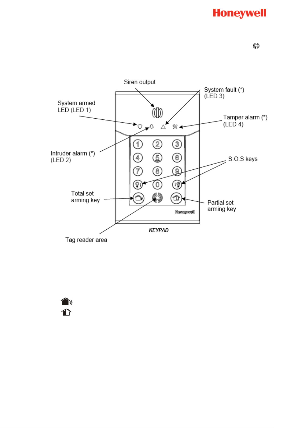
8
Ativa a definição total
Ativa a definição parcial
O teclado está equipado com um leitor de tag de proximidade, situado perto do símbolo ; o
teclado também apresenta uma sirene integrada como um elemente dissuasor e 4 LEDs
para o informar o estado do sistema.
Ativar usando o seu código ou tag
Pressione uma tecla de ativação no teclado e introduza o código ou apresente um TAG
registado.
O tom de ativação é emitido pelo teclado seguido pelos bipes de atraso de saída.
A ativação de definição de zona é concluída automaticamente no fim do atraso de saída.
Nota:
Certifique-se sempre de que a sua solicitação de ativação Total é seguida pelo tom
de ativação.
Desativar usando o seu código ou tag
Para desativar o seu sistema:
Introduzir um código válido ou apresentar um TAG registado.
Page 87

9
O tom de desativação é emitido pela sirene do teclado.
Desativar o sistema irá também parar as sirenes se o alarme for acionado.
Notas:
Certifique-se sempre de que a sua solicitação de desativação é seguida pelo tom de
desativação.
Desative sempre o sistema quando voltar a entrar nas instalações.
Manter o TAG na frente do teclado não reverterá o estado.
Page 88

10
Keyfobs
Enquanto no modo de instalação, pressione os botões de ativação total e de
ativação parcial simultaneamente durante 2 segundos.
Os LEDs correspondentes acender-se-ão durante 3 segundos.
Atenção
Não coloque o keyfob num local onde possa estar sujeito a altas temperaturas
Tenha cuidado para não deixar cair o seu keyfob. Manuseie-o com cuidado, caso
contrário, pode danificá-lo, descarregar a bateria ou provocar uma avaria.
Mantenha o keyfob afastado da humidade, poeira e água
Use apenas a bateria recomendada (CR2032 da Panasonic ou GP)
Como instalar
Um vídeo de ajuda pode ser encontrado aqui:
http://honeywell.total-connect.eu/video/TCC800M.mp4
Registar o keyfob:
Page 89

11
Ouvirá 2 bipes curtos a partir do leitor de
distintivos
Page 90

12
Indicação luminosa de Sucre Box
Luz 1
Luz 2
Luz 3
O painel de Sucre Box tem 3 luzes como exibido abaixo.
- Luz 1: Indicação sobre o estado da fonte de alimentação do painel
o Verde fixa: o painel está devidamente ligado à alimentação.
o Laranja a piscar: o painel está com alimentação da bateria apenas.
- Luz 2: Indicação do estado de ativação do sistema
o Desligado: O sistema está desativado
o Verde fixa: o sistema está em “Ativação total”
o Verde a piscar: o sistema está em “Ativação parcial”
o Laranja a piscar: foi detetada uma intrusão
- Luz 3: Indicação da rede de GPRS (apenas na instalação)
o Desligado: no módulo de GPRS (versão Sucre Box SUE8EU-STD-E)
o Laranja a piscar: Rede GPRS não encontrada
o Verde fixo: Rede GPRS encontrada
Nota: Para a versão Sucre Box SUE8EU-STD-E, a luz estará sempre apagada
como se não fosse usado cartão SIM
Nota importante: Na primeira instalação, Sucre Box atualizará automaticamente
com a versão mais recente de firmware. Esta fase, habitualmente demora
10 minutos mais pode demorar até 20 minutos. Durante este tempo, todos
os LEDs estão desligados.
Page 91

13
Instalar detetores e sirenes
Nota: Depois de instalar corretamente um dispositivo, ouvirá bipes curtos a partir do leitos
de distintivos ou do teclado.
Contacto de porta
Por favor, consulte o manual impresso fornecido com o produto para total orientação.
Instalar o contacto:
Dentro do quarto a ser protegido
Oponha as dobradiças para uma deteção mais rápida da abertura
Una o magneto à parte de abre, por exemplo a porta e não a moldura
Una o sensor à moldura da porta e não à porta
Com o magneto oponha a marca exibida no detetor
Com menos de 2 cm entre o magneto e o detetor quando a porta/janela está
fechada
De modo a que ao abrir completamente a porta ou a janela não danifique o
magneto
Não instalar o contacto:
No exterior
Perto de um ponto de água (ex.: casa de banho)
Detetores de movimento
Por favor, consulte o manual impresso fornecido com o produto para total orientação.
Instalar o detetor:
Numa área de circulação, preferentemente a apontar para as entradas (ex.: porta,
janela)
Preferencialmente numa esquina para otimizar a área de deteção
Num local que os animais não possam alcançar dentro de uma distância de 1.80 m
trepando à mobília, escadas, caixas ou qualquer outro objeto
Numa área de deteção sem obstáculos (ex.: cortinas, roupeiros)
A uma altura entre 2.30 m e 2.50 m acima do chão
Não instalar o detetor:
Num quarto mais pequeno do que a área de deteção (pelo menos 4 m2)
Page 92

14
No exterior
Perto de uma fonte de calor (ex.: chaminé, radiador, convetor, forno, disco de
fogão)
Perto de uma fonte de ar frio (ex.: ar condicionado)
No lado oposto a uma janela
Perto de um ponto de água (ex.: casa de banho)
Não pinte o detetor
Detetor de movimento com imagem
Por favor, consulte o manual impresso fornecido com o produto para total orientação.
Instalar o detetor:
Numa área de circulação, preferentemente a apontar para as entradas (ex.: porta,
janela)
Preferencialmente numa esquina para otimizar a área de deteção
Num local que os animais não possam alcançar em 1.80 m trepando à mobília,
escadas, caixas ou qualquer outro objeto
Numa área de deteção sem obstáculos (ex.: cortinas, roupeiros)
A uma altura entre 2.30 m e 2.50 m acima do chão
Não instalar o detetor:
Num quarto mais pequeno do que a área de deteção (pelo menos 4 m2)
No exterior
Perto de uma fonte de calor (ex.: chaminé, radiador, convetor, forno, disco de
fogão)
Perto de uma fonte de ar frio (ex.: ar condicionado)
No lado oposto a uma janela
Perto de um ponto de água (ex.: casa de banho)
Não pinte o detetor
Page 93

15
Detetor de vidro partido
1. Abrir o sensor.
2. Aparafusar a base à parede.
3. Manter as pilhas no local e retirar a patilha da
bateria para alimentar o sensor.
Requisitos de instalação
Instalar o detetor entre o vidro protegido e quaisquer revestimentos de janelas pesadas
que possam estar presentes. Quando estiverem presentes revestimentos de janelas
pesadas, o detetor pode ser montado na moldura da janela.
Não montar o detetor:
Em postes ou pilares
Em quartos com equipamento ruidoso (compressores de ar, ferramentas elétricas,
etc.), se este equipamento for operado quando o detetor estiver ativado.
Onde a visão do detetor para o vidro possa estar obstruída intencionalmente
Como instalar
Orientar o microfone para a melhor linha do local para o vidro protegido. Se montado no
teto a extremidade do microfone deve estar de frente para o vidro protegido.
Page 94

16
4. Fechar o sensor.
Como mudar as baterias
Tempo médio de duração da bateria: 4 anos
Tipo: CR123A
Quantidade: 2
1. Abrir o sensor.
2. Mudar as baterias (tipo CR123)
3. Fechar o sensor.
Page 95

17
Sensor de choque
1. Retirar a tampa do sensor.
2. Montar o sensor numa superfície sólida com os
parafusos fornecidos. Existem dois orifícios de
montagem.
3. Apenas para SHKC8M, monte o magneto
(fornecido) adjacente à faixa de alinhamento
do sensor.
Requisitos de instalação
A série SHK(C)8M é concebida para proteger a zona envolvente de janelas e portas e é
usada para detetar ataques forçados sobre a superfície na qual está montado.
É capaz de detetar dois tipos diferentes de ataques forçados:
Ataque forte: o dispositivo enviará um alarme para qualquer evento simples de
choque cuja intensidade exceda o nível de sensibilidade de ataque forte definido
na fábrica.
Ataques repetidos: o dispositivo enviará um alarme depois de um número definido
(controlável) de choques consecutivos, cuja intensidade exceda o nível de
sensibilidade de ataque repetido definido na fábrica dentro de um período de
8 segundos
Como instalar
Page 96

18
4. Voltar a colocar a tampa.
Como mudar as baterias
Tempo médio de duração da bateria: 4 anos
Tipo: CR123A
Quantidade: 1
1. Retirar a tampa.
2. Substituir a bateria.
3. Voltar a colocar a tampa.
Page 97

19
Detetor de monóxido de carbono
Alarme de
CO
300 mm
150 mm
AR PARADO
NÃO
COLOCAR
AQUI
1 a 3 m
1 a 3 m
Alarme de
CO
Alarme de
CO
Aproximadamente
1 a 2 m
300 mm
Requisitos de instalação
Onde colocar o detetor de monóxido de carbono:
Idealmente, instale um alarme de monóxido de carbono em:
Qualquer quarto que contenha um aparelho de queima de combustível
Page 98

20
Não monte a tampa na base quando o interruptor
estiver na posição X. Garanta que o interruptor está
na posição OK.
As baterias do CO8M não são substituíveis; o
produto é alimentado para a vida.
Quando a unidade tiver completado 6 anos de
funcionamento e a luz âmbar piscar três vezes a
cada 50 segundos e emitir um bipe em simultâneo.
Isto indica que o alarme alcançou a data do fim da
sua vida e deve ser substituído. Esta data está
escrita no produto.
1. Retire a placa de instalação da embalagem e a
caixa de proteção.
Quartos remotos onde os ocupantes passem uma quantidade considerável de
tempo
Qualquer quarto de dormir
Todavia, se o número de alarmes de monóxido de carbono a serem instalados for
limitado, considere os seguintes pontos quando decidir onde é melhor instalar o(s)
alarme(s):
Se houve um aparelho num quarto onde durmam pessoas, coloque um alarme de
CO neste quarto
Coloque um alarme num quarto onde o(s) ocupante(s) passe(m) a maior parte do
tempo (ex.: sala de estar)
Numa kitchnette, coloque o alarme de CO o mais afastado possível do aparelho de
cozinha, mas perto de onde a pessoa dorme
Atenção
Como instalar
Page 99

21
2. Coloque a placa de instalação no teto ou parede
exatamente onde pretende montar o alarme de CO.
Com um lápis, marque a localização dos orifícios
dos dois parafusos.
3. Perfure os orifícios usando uma broca de 5.0 mm
através do centro das localizações marcadas.
Atenção: Quando perfurar orifícios, tenha
cuidado para evitar qualquer fiação elétrica
já presente no teto ou na parede.
4. Pressione os parafusos de amarração de plástico
fornecidos nos orifícios perfurados e aparafuse a
placa de instalação no teto ou parede.
5. Cuidadosamente, alinhe o alarme de CO na base,
depois pressione e torça.
Depois de alguns segundos (até 15 segundos) dois
bipes confirmarão a inscrição com sucesso.
6. Pressione o botão de teste para garantir que o
alarme funciona.
Page 100

22
Detetor de fumo
Por favor, consulte o manual impresso fornecido com o produto para total orientação.
Como instalar
Um vídeo de ajuda pode ser encontrado aqui:
http://honeywell.total-connect.eu/video/DFS8M.mp4
Requisitos de instalação (DFS8M)
O fumo sobre em direção ao teto, de seguida espalha-se horizontalmente, desta forma o
local ideal para fixar o sensor é no meio de um quarto.
 Loading...