

Page 1

31-00118EFS-01
LCBS Connect Solution
APPLICATION MANUAL
TABLE OF CONTENTS
Introduction .................................................................................................................................................................. 2
Background....................................................................................................................................................................................... 3
Automatic Building Schedules ................................................................................................................................ 4
Scheduling a Holiday .................................................................................................................................................................... 5
Heating, Heat Pump Control .................................................................................................................................... 6
Heating Theory and Operation ................................................................................................................................................. 6
Basic Gas and Electric Heating ................................................................................................................................................ 6
Air to Air Heat Pump ...................................................................................................................................................................... 6
Droop, Comfort and Saving Heat Pump Mode ................................................................................................................... 7
Discharge Air Temperature High Limit Control.................................................................................................................. 7
Cooling, Dehumidification, Economizer Control ................................................................................................7
Cooling Theory and Operation .................................................................................................................................................. 7
Cooling Operation .......................................................................................................................................................................... 8
Dehumidification Theory and Operation .............................................................................................................................. 8
Method #1: Cooling On, Cycle Heating ................................................................................................................................. 8
Method #2: Simple Humidification......................................................................................................................................... 8
Method #3: Dehumidification extended cooling minimum run time ....................................................................... 9
Fresh Air Economizer Control .................................................................................................................................. 9
Theory and Operation Economizer ......................................................................................................................................... 9
General Economizer Operation ................................................................................................................................................ 9
Honeywell Integrated Economizer Control Described .................................................................................................... 10
Honeywell Integrated Economizer Control, Climate Zones .......................................................................................... 12
Honeywell Integrated Economizer Control - High Limit and Changeover Strategies........................................ 12
Strategy 1: Differential Enthalpy with Fixed Dry Bulb Temperature Limit .............................................................. 12
Strategy 2: Outdoor Air Enthalpy.............................................................................................................................................. 12
Strategy 3: Differential Temperature ...................................................................................................................................... 12
Strategy 4: Outdoor Temperature ............................................................................................................................................ 12
Low Limit Temperature Override Control ............................................................................................................................. 13
Freeze Stat Operation ................................................................................................................................................................... 13
Advanced Temperature Control Fundamentals..................................................................................................13
Proportional Control and the Concept of Differential and Throttling Range......................................................... 13
Proportional Control...................................................................................................................................................................... 13
Set point and Differential Refresher - On Off, Digital Control...................................................................................... 14
Integral Action Primer and Refresher Course for Some.................................................................................................. 15
Derivative Control........................................................................................................................................................................... 17
Demand Controlled Ventilation............................................................................................................................... 17
Theory and Operation Demand Controlled Ventilation .................................................................................................. 17
DCV Operation ................................................................................................................................................................................. 17
Adaptive Intelligent Recovery..................................................................................................................................18
Page 2

LCBS CONNECT SOLUTION
Multispeed Fan ............................................................................................................................................................ 20
Multispeed Fan Theory and Operation................................................................................................................................... 20
Two speed motor .............................................................................................................................................................................20
VFD application................................................................................................................................................................................20
Direct drive "ECM" motor..............................................................................................................................................................20
Theory and Operation Accessory Loops ............................................................................................................... 23
How do Accessory Loops work?.................................................................................................................................................23
Service Alerting Theory and Fundamentals ........................................................................................................24
How does service alerting work?...............................................................................................................................................25
Terminal Load, Zone Demand Alert. ........................................................................................................................................ 25
Space Humidity Alert.....................................................................................................................................................................25
Space Zone Carbon Dioxide Level Alert .................................................................................................................................26
Differential Pressure Alerting, Filter Loading ......................................................................................................................26
Alerting Details................................................................................................................................................................................. 27
Appendix, Wiring Diagrams ...................................................................................................................................... 30
1. Master Points List - Configurable and Fixed Function Points.................................................................................30
2. Master Application Inventory - All Wiring Diagrams....................................................................................................30
3. Configurable Input and Output Assignments Wiring Diagram ...............................................................................31
4. Fixed Input and Output Assignments Wiring Diagram ...............................................................................................32
5. Two Heat Two Cool Integrated Economizer Single Temperature Changeover Limit ......................................33
6. Two Heat Two Cool Integrated Economizer Differential Enthalpy Changeover and
Temperature Limit.....................................................................................................................................................................34
7. Two Heat Two Cool Integrated Economizer Differential Enthalpy Changeover and Temperature
Limit and Demand Controlled Ventilation.......................................................................................................................35
8. Three Heat Three Cool Multispeed Fan with Variable Frequency Drive ...............................................................36
9. Single Stage Heat Pump with Economizer Differential Enthalpy Changeover and
Temperature Limit.....................................................................................................................................................................37
10. Two Stage Heat Pump with Economizer Differential Enthalpy Changeover and Temperature Limit ...38
11. Simple Dehumidification......................................................................................................................................................39
12. Two Speed Fan with Discrete Fan Outputs Two Heat and Two Cool ...................................................................40
13. Outdoor Ambient Lighting Control with Photosensor Input to Control Outdoor Light Level ..................41
14. Sylk Sensor Installation Relating to LCBS Connect Controller .............................................................................42
INTRODUCTION
The LCBS Connect Solution features controllers that support multiple CVAHU applications, including rooftop units, split
systems and air to air heat pumps and a new Gateway that permits controller data to be sent from individual CHAHU
controllers via the internet to the new LCBS Connect Cloud. The new Honeywell Cloud capability gives our control system
users unprecedented access to data remotely via standard smart phones, tablets, and personal computers. Honeywell
also performs data analysis, called “analytics,” that will permit service contractors and building owners to effectively and
efficiently manage HVAC assets. Here are a few specific features of the new LCBS Connect solution.
— Occupancy Control. Daily and holiday schedules are available to ensure that building occupants, employees, and
visitors are comfortable when they are in the building and that owners achieve maximum energy savings when no
one is occupying the building. Honeywell patented Adaptive Intelligent Recovery monitors outdoor and indoor climate conditions to ensure comfortable conditions when building occupants arrive.
— Advanced Sensing. Supports multiple space temperature sensors (Up to five) for effective temperature value
(Average, Minimum, Maximum, and Smart) and options for return air sensing. Supports space and return air temperature, humidity, and CO2 sensing.
— Heating and Cooling Control. Provides three stages of heating and cooling for conventional equipment and up to
three compressor stages for air to air heat pumps. LCBS Connect heat pump controllers support up to two (2)
stages of auxiliary heat.
— Economizer Control. Supports nine different economizer strategies that address all climatological zones in North
America.
— Dehumidification Control. Three (3) dehumidification strategies for dehumidification control are supported.
First, if the equipment is capable, a reheat mode can be programmed to provide precise dehumidification operation. Second, dehumidification equipment can be controlled through a direct LCBS Connect output to provide
dehumidification. Third, extended minimum cooling runtime can be selected supporting the dehumidification
process.
31-00118EFS—01 2
Page 3

LCBS CONNECT SOLUTION
— Accessory Loop, Multispeed Fan Control. Each LCBS Connect controller provides the ability to configure custom
control loops to control other equipment including exhaust fans, exhaust pressurization loops, cabinet unit heaters, blower coils, and outdoor lighting circuits based on ambient light level. These loops are called "Accessory
Loops." LCBS Controllers also provide unprecedented control of CVAHU fans that we call Multispeed Fan. This feature not only ensures building occupant comfort, but when applied properly, results in energy cost avoidance to
building owners.
— Honeywell Cloud Based Remote Control and Service Analytics… A New Honeywell Feature! Data is sent
securely from a building site via the internet to the Honeywell Cloud where extensive analysis is performed. The
output of this analysis is useful information that will allow service contractors to do service more efficiently and
effectively and retain valuable service contracts.
Background
The LCBS Connect system provides comprehensive control options for constant volume air handling units (CVAHU). In
addition to heating, air conditioning, dehumidification, and ventilation applications, critical data from LCBS Connect
controllers is collected, stored, and analyzed in the Honeywell Cloud. The data can be used for logging, sophisticated
graphic display, advanced service alerting and "big data" analytics. Honeywell data scientists and engineers are relying
on hundreds of years of control and service experience to write analytics that will help service contractors assist building
owners to predict and prevent service issues from occurring, resulting in superior equipment uptime and extended HVAC
equipment life. These analytics run in the cloud 24 hours a day, 365 days a year.
Honeywell has an incomparable industry reputation for providing precise temperature control, superior remote and local
operator interface experience. With the addition of cloud based data collection and data analytics, Honeywell steps to the
front again.
The primary focus for LCBS Connect is control of CVAHU rooftop units and split systems. Over 60% of commercial
buildings in North America are heated and cooled by CVAHU packaged and split systems. The average age of this HVAC
equipment is approximately eight (8) to 10 years. Due to lack of appropriate service, many suffer from operational
problems including temperature, pressure, humidity sensing devices that are out of calibration, refrigeration circuits
improperly under and overcharged for a variety of reasons, economizer ventilation cycles that have ceased to function, air
flow systems improperly sized delivering substandard air flow, and thermostats in common buildings that "fight" each
other due to improper occupant intervention.
LCBS Connect. Extending HVAC Equipment Life
The average estimated life of packaged constant volume air handling systems is about 17-25 years, depending on where
the system is located. At eight (8) years, these systems are ripe for 1] restorative service and 2] re-control for reasons
listed above. With service contractor assistance, a user of these systems can delay capital appropriation and expenditure
by up to five (5) years by restoring these units to initial, "as built" specified operation. Restored equipment operates less
resulting in lower energy costs. Ongoing maintenance costs are reduced as "tuned up" equipment operates efficiently and
effectively. After this work is done, Honeywell offers LCBS Connect Cloud Services that will help HVAC service contractors
keep HVAC equipment operating in a highly efficient manner and delivering extended equipment life.
What you will learn by reading this document
Each section consists of three (3) sections. First, "theory and operation" includes a short description about
why we do what we do and how it works. Second, a more complete description of "how it works" is provided.
Third, wiring diagrams are provided to demonstrate how an installer wires up the application. Technically, this
is in the "appendix" of this document.
Controls in Small Commercial Buildings
In commercial buildings, it is essential that heating and air conditioning systems operate in a properly configured,
automatic manner. In a small commercial building, HVAC operational experts are often HVAC service contractor
specialists or by a few subject matter experts within the building. Additionally, control performed in a small commercial
buildings is typically more complex than in a residential dwelling. Heating, cooling, fan operation, ventilation, indoor air
quality, dehumidification, and various other functions can all operate successfully in a small commercial building but due
to economics, we can't count on an experienced controls experts to be present to troubleshoot building controls
problems.
Herein lies a point of concern for servicing contractors and building owners as we strive to effectively control small
commercial buildings. Honeywell and our contractor business partners need to provide basic local control for building
owners. The more power and authority that building occupants have is desirable, but can also lead to undesirable system
operation, particularly higher energy use and HVAC equipment wear and tear. It is important that Honeywell LCBS
Connect contractors to educate building owners about key control requirements.
3 31-00118EFS—01
Page 4

LCBS CONNECT SOLUTION
Here is a typical case of how control systems are designed to work and how building
occupant's well intentioned efforts can cause facility operational problems.
Typical CVAHU systems observe a control operation strategy called "automatic heating and cooling changeover." This
operation ensures that mandatory, building code compliant heating, cooling, and ventilation occurs in a commercial
building. If the system permits, a building occupant can change this operational to "cooling" or "heating" only. A well
intentioned building occupant may simply be hot or cold and may change settings to achieve personal comfort.
This action is not without consequences. If this setting is erroneously left in the "cooling" or "heating" position, when
climate changes, mechanical heating and cooling is locked out. This will lead to an inevitable service call at 1] will cost the
building owner hundreds of dollars due to service contractor interaction or 2] a service contractor who can't bill for the
call due to service contractor type.
Enter LCBS Connect
A contractor that has adopted LCBS Connect will have remote access to the customer's site and will allow
remote remediation of the problem and will save a truck roll to the customer's site. Providing local access to
building occupants should be weighed and discussed carefully with the building owner and those paying for
maintenance and utility bills.
AUTOMATIC BUILDING SCHEDULES
Automatic Occupancy Control Theory and Operation
For building owners and operators, we assume two basic things: indoor commercial building environments need to be
heated, cooled, and ventilated for human health and comfort during the time humans occupy a building. There are
important secondary issues relating to occupancy including management and protection of assets during periods when
humans don't occupy building spaces including protection of plants, precious artwork, plumbing, paper products, and
wall and floor coverings. Excessive heat, cooling, and humidity conditions can cause damage to building.
Ensuring that building space is conditioned to make sure building occupants are comfortable is quite different than
making sure that it is warm or cool enough to protect plumbing from freezing and from wall paper and paint from peeling
off the wall. In general, the energy required to operate systems to provide human comfort is 2-5X the cost to protect
assets in a building without humans present.
How does occupancy methodology work?
LCBS Connect allows HVAC service contractor and customers to develop schedules via LCBS Connect tools including
local operator interface or remote cloud based tool to match building occupancy schedules. These schedules can be also
be set to accommodate occurrence of special events and holidays.
To ensure that proper comfort conditions are achieved by desired occupancy, Honeywell has developed an algorithm to
meet these needs. Honeywell's answer to this recovery process is called "Adaptive Intelligent Recovery™" Implementing
this correctly will require knowledge by the HVAC professional regarding the rate at which the HVAC system can provide
restorative heat injection (heating), heat removal (cooling) in a building space. This recovery algorithm also keeps HVAC
systems from starting suddenly and creating an excessive electrical in-rush that can result in undesirable utility demand
control charges. The payoff to getting this "right" is huge. We want to keep building occupants and patrons comfortable
and control energy usage and associated costs. Honeywell Adaptive Intelligent Recovery permits us to meet this
requirement.
LCBS Connect controllers also have the ability to control temperature to "standby" set points. This set point technique is
typically applied to building spaces that are randomly and infrequently occupied. A good example of the application of
the standby set point is for an office or meeting room. The standby heating set point is always set the same or slightly
below the standard occupied set point and the standard cooling set point is always set the same or slightly above the
standard occupied set point. If the space temperature is being controlled at the standby set point, it is assumed that the
building space being controlled is unoccupied. The benefit of using the standby strategy is twofold… 1] to make sure that
building occupants are comfortable when they enter randomly occupied spaces and 2] reduce energy usage by altering
HVAC control and reducing ventilation when building occupants aren't in the randomly occupied building space. The
transition of standby set points from "standby" to "occupied" is typically initiated by a "motion sensor" detecting
occupancy in the building space. Likewise, if the motion sensor does not detect motion, the set point is transitioned from
"standby" to "unoccupied."
In order to comply with building codes, during scheduled "occupied" periods, the supply fan will run 100% on. Why? Most
prevailing building codes require "continuous fresh air ventilation" and a specific requirement of fresh air, outdoor air
based on an aggregate CFM per hour or CFM per person in the building space. Without going into detail, it is literally
31-00118EFS—01 4
Page 5
LCBS CONNECT SOLUTION
impossible to provide minimum fresh air ventilation without supply fan moving air. During "standby" and "unoccupied"
periods, the supply fan operates in conjunction with a call for heating or cooling and ventilation is disabled, as we assume
that people are not in the building space.
LCBS Connect users can permit the supply fan to run only on a call for heating or cooling during "occupied" periods, but it
is discouraged and defies prevailing the building ventilation code. Further, cycling the fan on a call for heating or cooling
can degrade the life of the fan motor, fan belts, and associated fan accessories.
LCBS Connect controllers have the ability to control local equipment based on an eight (8) day scheduling strategy, seven
days of the week featuring four events per day and a "holiday" schedule featuring four events per day.
Let's get into some specific details.
There are four (4) programmable events that are available for each event.
— Occupied. This indicates the beginning of a time period, associated with an "on" condition or observance of "occu-
pied" set points when building occupant typically occupy building zones.
— Unoccupied. This indicates the beginning of a time period, associated with an "off" condition or observance of
"unoccupied" set points when building occupants typically leave the building.
— Standby. This indicates the beginning of a time period, associated with observance of "standby" set points, were
ventilation and fan are controlled conforming to unoccupied control behavior. Using "standby" set points and process can result in energy savings during traditional occupied hours. During the standby period, if an occupancy
sensor is assigned to the controlled zone, and it detects people in the controlled zone, occupied set points and
occupied ventilation practice is observed. If this occupancy sensor does not detect movement, unoccupied set
points and ventilation practice is observed. Tip: Use standby set points in infrequently occupied building zones
including meeting rooms and break rooms.
— Available. This is a fourth condition indicating that a change of event state can be programmed, configured, exe-
cuted. This is also referred to as "un-configured."
How it works
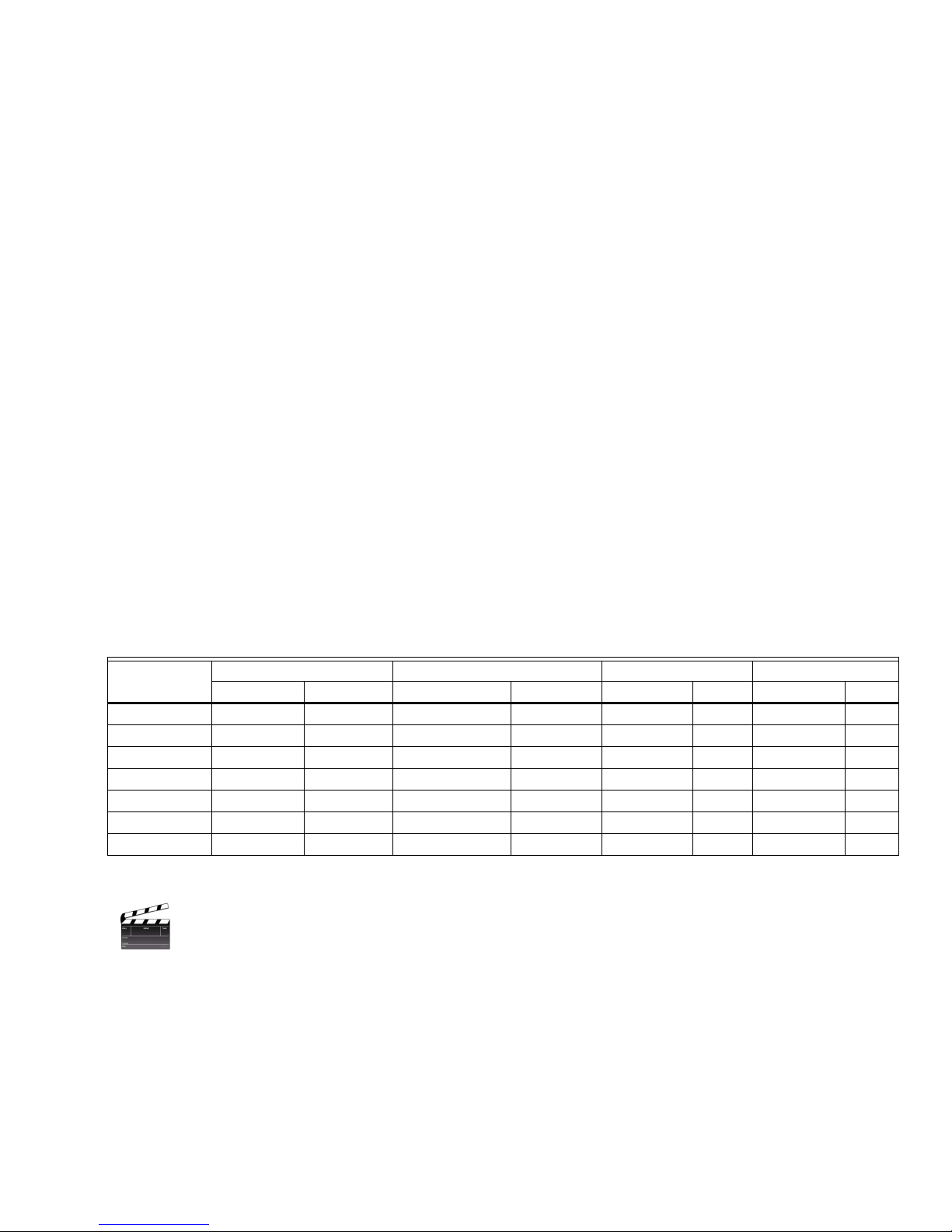
Date and Time is available for each LCBS Connect controller. Each LCBS controller can support for events. For example,
assume that I open my store at 7:00 AM and close it at 7:00 PM Monday through Friday. My store is open at 7:00 AM and
closes at 1:00 PM on Saturday. I'm closed on Sunday. Find constructed table of required schedules below:
Table 1.
EVENT 1 EVENT 2 EVENT 3 EVENT 4
DAY
MONDAY OCCUPIED 7:00AM UNOCCUPIED 7:00PM AVAILABLE AVAILABLE
TUESDAY OCCUPIED 7:00AM UNOCCUPIED 7:00PM AVAILABLE AVAILABLE
WEDNESDAY OCCUPIED 7:00AM UNOCCUPIED 7:00PM AVAILABLE AVAILABLE
THURSDAY OCCUPIED 7:00AM UNOCCUPIED 7:00PM AVAILABLE AVAILABLE
FRIDAY OCCUPIED 7:00AM UNOCCUPIED 7:00PM AVAILABLE AVAILABLE
SATURDAY OCCUPIED 7:00AM UNOCCUPIED 7:00PM AVAILABLE AVAILABLE
SUNDAY AVAILABLE AVAILABLE AVAILABLE AVAILABLE
EVENT TYPE TIME EVENT TYPE TIME EVENT TYPE TIME EVENT TYPE TIME
Scheduling Summary
LCBS Connect controllers have a default schedule built into them. The LCBS Connect controller will work
when you pull them out of the box. The default schedule is 6:00 AM to 6:00 PM Monday through Sunday. If
you want to set up different occupancy schedules, it's a good idea to refer to appropriate documentation
form in your support package, print it out, and write out the schedules you want to implement. Go to LCBS Connect wall
module or LCBS Connect Remote User Interface and program desired times.
Scheduling a Holiday
LCBS Connect controllers support the following holiday scenarios for one event schedule. This will be improved in the
future, particularly when we implement "Cloud Based Scheduling":
Date specific: A good example of this is July 4 for our national holiday and December 25 for Christmas. This could be
obvious, but isn't intended to be insulting to the reader. July 4th never changes as a date, but the day of week does.
5 31-00118EFS—01
Page 6

LCBS CONNECT SOLUTION
Day specific: A good example of this is Thanksgiving. This date is always on the last Thursday of the month of November.
Thursday, as the day we celebrate American Thanksgiving, never changes, but the date does.
Extended date: Establish a specific day or date. The ability to extend this holiday any number of days is offered. For
example, if we celebrate Thanksgiving and our establishment will be closed on the day following Thanksgiving, enter two
(2) days in the proper configuration field.
Holiday Scheduling Summary
LCBS Connect controllers do NOT have a default holiday schedule built into them. If you want to set up
different occupancy schedules on various holiday dates and times, please do so. Go to LCBS Connect wall
module or LCBS Connect Remote User Interface and program desired times.
HEATING, HEAT PUMP CONTROL
Heating Theory and Operation
There are two key theoretical objectives for heating. First, we have an objective to keep building occupants comfortable by
providing heat during heating seasons during periods when occupants occupy buildings. Second, we need to keep
building assets warm enough so that no building damage occurs to valuable assets, particularly when it's very cold
outdoors. LCBS Connect controllers are designed so they don't operate heating system in an inefficient manner, on in a
manner where damage occurs to the heating systems. Some examples to protect heating equipment are minimum on
and off times for gas and electric heating elements and heat exchangers, high limit heating controls, and lockout based
on low sensed ambient or outdoor air temperature.
Basic Gas and Electric Heating
There are two basic systemic direct heating methods that LCBS Connect supports; standard staged heating that features
natural gas heat exchangers and staged electric heat that typically include electric duct heaters. For gas heating option,
LCBS Connect can either be set to energize supply fan operation on a call for heating directly or the supply fan can be
controlled by a fan and limit device. The latter is quite common with gas heating systems. We support control of three
stages of heat, three stages of cool. Further, electric heat can typically be cycled more frequently and aggressively than
gas heat. LCBS Connect accounts for both methods and all settings.
Air to Air Heat Pump
In North America, there are areas where natural gas is not available or where electrical energy is relatively inexpensive.
This makes Air to Air Heat Pumps financially and operationally viable. The air to air heat pump features mechanics and
electronics that reverse the refrigeration cycle in an air conditioning unit and pumps warm refrigerant into the evaporator
coil to provide heat. Another heat pump that we find in North America is the "water source" or "geothermal" heat pump.
The Air to Air Heat Pump is a widely used solution that spans residential and commercial applications in North America
and is the focus of this release. We will be able to control Water Source Heat Pumps and associated boiler and cooling
tower plans in the 2.0 release of LCBS Connect.
A standard method of controlling the flow of refrigerant in a heat pump system is by controlling the position of the
"reversing valve." There are two prevalent methods are 1] energizing the reversing valve on a call for cooling and 2]
energizing the reversing value of a call for heating. For the former, the terminal designation on the low voltage terminal
strip on the heat pump is "O" and for heating, "B." Please note! There is a third method of heat pump control, popularized
by Carrier and Carrier brands. This method features standard Y1 and W1 cooling and heating control with the reversing
valve internally controlled. It may be necessary to adjust heating minimum on times to protect heating compressor cycle.
50°F
OUTDOOR
AIR
TEMPERATURE
ADJUSTABLE
PARAMETERS
35°F
SYSTEM COMPRESSOR ONLY OPERATING
IF INDOOR AIR TEMPERATURE “DROOPS”
BELOW HEATING SETPOINT, SHUT OFF
COMPRESSOR AND USE AUX HEAT
SYSTEM FURNACE AND AUXILIARY
HEAT ONLY OPERATING
ADJUSTABLE
OUTDOOR
TEMP
AUXILIARY
LOCKOUT
ADJUSTABLE
OUTDOOR
TEMP
BALANCE
POINT
31-00118EFS—01 6
TIME
Fig. 1.
MCR36696
Page 7
LCBS CONNECT SOLUTION
Depending on the geographical location of our customer's building and of an air to air heat pump, electric auxiliary heat
may be required. In northern United States, if a heat pump compressor is not protected with a compressor heater, the
compressor must be locked out to prevent damage to it and electric heat must be used to heat building space. The latter
can be expensive, thus we provide adjustable settings to attempt to help contractors and building owners avoid excessive
electricity use. The LCBS Controller has an adjustable outdoor air limit sensor that can lockout heat pump compressor if
outdoor air temperature falls below an adjustable level. Given this potential extraordinary expense, we've developed
several techniques to attempt to reduce the cost of operation of electric heat. Honeywell provides an option to operate
electric heat in a standard manner; this concentrates on traditional comfort. It's called the "comfort" mode. Look for this
as you configure your air to air heat pump; it's a selectable option. If the building owner can tell their employees, staff to
have a sweater ready on very cold days, Honeywell offers the "savings" mode. This automatically depresses the heating set
point and results in electric heat cycling less, maintaining a lower heating set point.
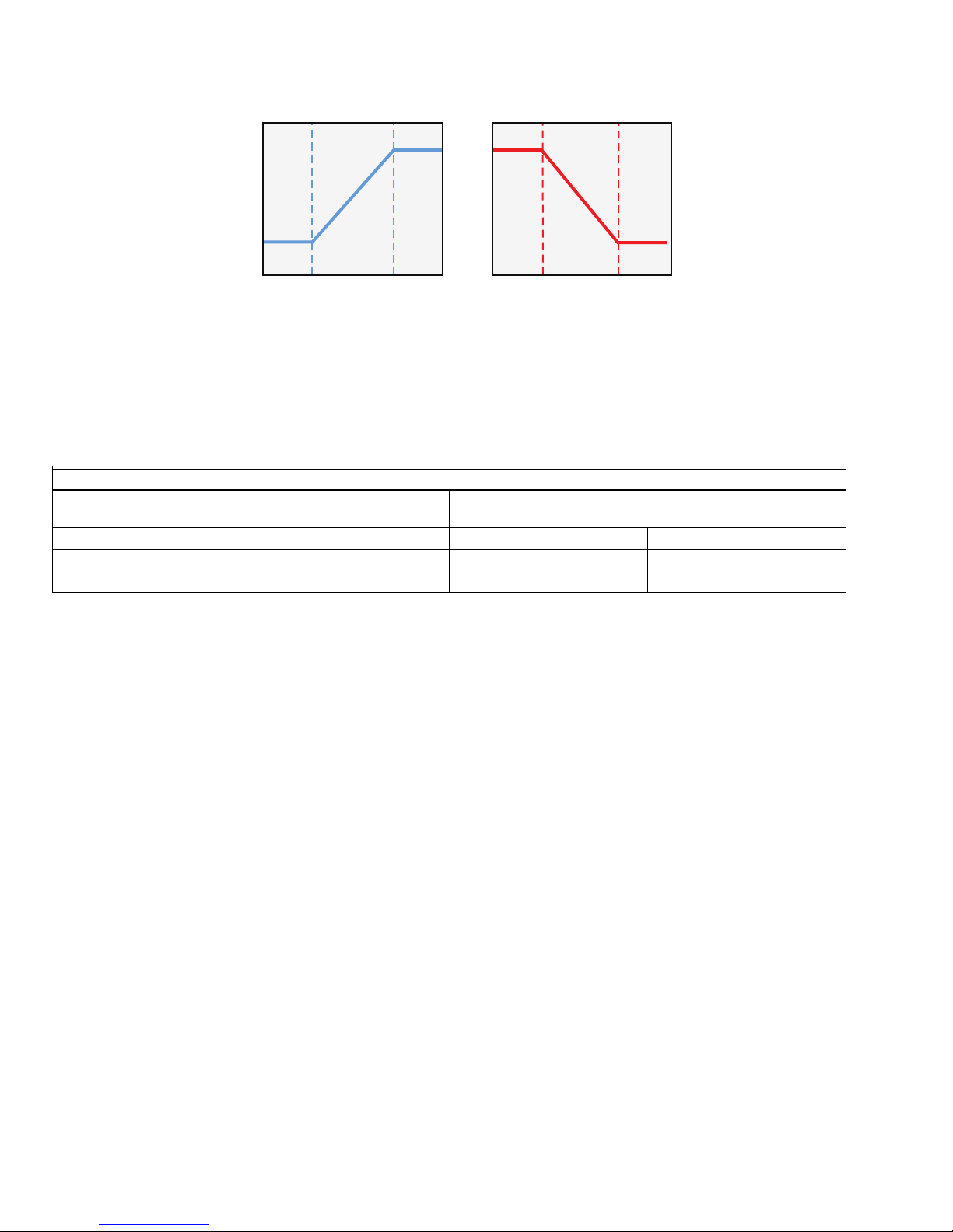
Droop, Comfort and Saving Heat Pump Mode
What is "droop?" Simply put, it's a temperature value that "droops" below standard occupied or unoccupied heating set
point. Heat pumps do a super job of heating as long as it's not too cold outdoors. As we've described a few times,
sometimes the pump just loses the battle to provide adequate heating. When this happens, the LCBS Connect control
system supplements the compressor and begins using "fossil fuel" heating, typically electric strip heaters. So, standard
heat pump cycle is designed to terminate heat pump usage below established outdoor air temperature where the
efficiency is less than electric or gas heat.
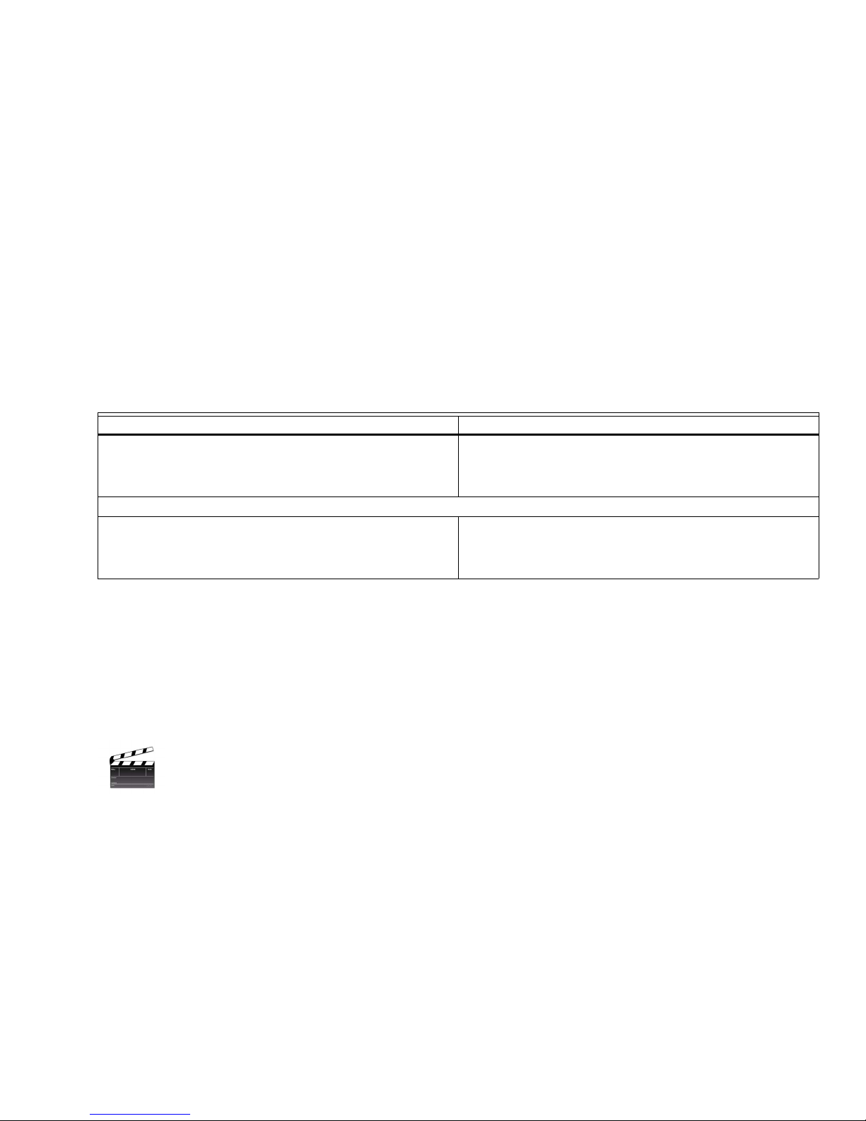
Here's a summary of the "Comfort" and "Savings" mode:
"COMFORT" MODE "SAVINGS" MODE
Depending on outdoor limits set, the compressor, the
compressor acting in unison with auxiliary heat, or auxiliary
heat operates to maintain heating setpoint.
COMMENTS. BENEFITS, SHORTCOMINGS
Comfort is our prevailing concern for our employees,
guests, and patrons.
If "savings" mode is selected and if auxiliary heat is not
locked out, the heating sepoint is depressed by "x" degrees.
this minimimzes the use of auxiliary heat and avoids energy
cost.
Pushes pump operation thus saves energy. the more
aggressive the "savings" setpoint is, the more likely that
building zones will become cold. take care to select
parameters properly.
Discharge Air Temperature High Limit Control
While heating, it is possible that discharge air temperature may increase beyond an unacceptable limit. To avoid this, the
LCBS Connect controller features discharge air temperature high limit control. When discharge air temperature increases
above the discharge air high limit set point, the heating equipment is controlled to maintain the discharge air
temperature to the set point. Let's assume that the discharge air set point is 120°F. If the discharge air temperature
increases above 120°F then the heating equipment is cycled off. When it falls back below the limit minus the switching
differential, it will be allowed to cycle back on. Please note: Your HVAC unit will feature a high limit heating control.
Ensure that the LCBS Connect setting is HIGHER than that of the unit being controlled.
Heating Summary
LCBS Connect controllers have a wide array of heating options. As with most functions, if you are
commissioning a simple single heat conventional system, the LCBS Controller will work "out of the box." It
will be designed to work at 68°F occupied setting and 62°F unoccupied setting. You will have access to
changing proportional band, integral gain, and derivative gain if you wish. It is HIGHLY RECOMMENDED that you
DON'T alter these parameters unless a Honeywell LCBS Connect support professional tells you to do so. You will need to
make some basic changes to the device if you are commissioning a heat pump. There are a number of options described
in this document that will allow you to alter basic heat pump operation; most are provided so that the heat pump operates
in an efficient manner. It is recommended that you don't change preconfigured parameters.
COOLING, DEHUMIDIFICATION, ECONOMIZER CONTROL
Cooling Theory and Operation
There are two key operational objectives for cooling. First, we have an objective to keep building occupants comfortable
during assumed cooling seasons during periods when occupants occupy buildings. A close following objective is to keep
building assets cool and dehumidified enough so that no building damage occurs when it's very warm and humid
outdoors. LCBS Connect controllers need to protect cooling systems so they don't operate in an inefficient manner, on in
a manner where damage occurs to the cooling systems. Some typical examples to protect cooling equipment are
7 31-00118EFS—01
Page 8
LCBS CONNECT SOLUTION
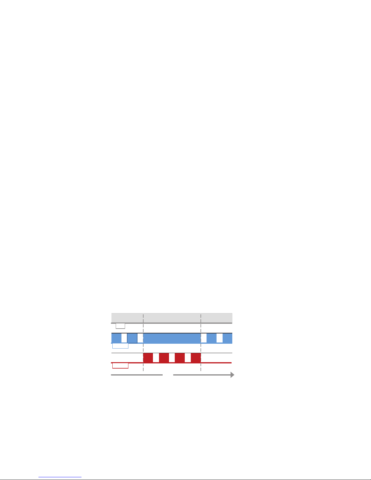
ON
OFF
ON
OFF
ON
OFF
DEHUMIDIFICATION CONTROL
WORKS IN “COOLING MODE” ONLY, DOES NOT WORK IN “HEATING MODE”
TIME
HUMIDITY LIMIT,
SETPOINT EXCEEDED
HUMIDITY LIMIT,
SETPOINT ABATES
FAN
COOLING
HEATING
FAN ON CONTINUOUSLY (OCCUPIED, STANDBY PERIOD)
COOLING CYCLING, LOCKED ON, CYCLING
HEATING OFF, CYCLING, OFF
MCR36697
minimum on and off times for compressor operation and lockouts based on low sensed ambient or outdoor air
temperature. Freeze stat operation protects HVAC system from being damaged as systems are cycled off if system
freezing conditions are detected.
Cooling Operation
LCBS Connect controllers support control of compressor stages and DX refrigeration circuits. Up to three stages of
cooling can be controlled by LCBS Connect controllers. There is a freeze stat sensor control input that monitors potential
freezing temperatures and serves as a low limit. The sensor is typically mounted against the cooling coil and protects it
from freezing, resulting in coil damage and can also make sure that unheated outdoor compressors aren't "slugged." The
LCBS Connect controller shuts off the supply fan, the compressor and closes the outdoor air damper if a frozen coil
condition is detected. Also the discharge air sensor utilizes a control tactic called a "low limit", where if the discharge air
temperature falls below the low limit, compressor stages will be turned off until the condition goes away or all stages are
off.
Dehumidification
Dehumidification Theory and Operation
Dehumidification is an important part of control operation in many parts of the United States. High humidity can result in
two major problems. First, high relative humidity can result in uncomfortable conditions for building occupants. Second,
relative humidity is destructive to architectural elements like carpeting, wallpaper, paint, and art work.
How does LCBS Connect dehumidification work?
Three (3) dehumidification strategies for dehumidification control are supported. First, cooling and heating can be
programmed to operate in a reheat sequence to provide precise dehumidification operation. Second, dehumidification
equipment can be controlled through a direct LCBS Connect output to provide dehumidification. Third, extended cooling
extended runtime can be selected that can enhance and augment the dehumidification process. These are described in
detail below.
Method #1. Cooling On, Cycle Heating
The reheat dehumidification control algorithm works only when system in in cooling mode. The call for dehumidification
occurs as a result of humidity level rising above the dehumidification limit. If cooling is not operating, it becomes
energized. A single stage of heating is energized in conjunction with the call for dehumidification. When humidity drops
below set point less differential, hysteresis, the heating stage is cycled off and cooling cycles off. If a call for cooling
continues, cooling remains on and cycles per temperature control algorithm. Method #1 can be augmented with Method
#3, described below.
NOTE: It's important to observe the configuration of heating and cooling coils in the constant volume that you intend to
apply the dehumidification algorithm. The heating coil must be downstream of the supply fan and cooling coil for
the dehumidification algorithm to work properly.
Method #2: Simple Humidification
In the "simple dehumidification method," the algorithm simply senses space or return air humidity and energizes a
designated digital output until the call for dehumidification abates. Method #2 can be augmented with Method #3,
described below.
31-00118EFS—01 8
Fig. 2.
Page 9

LCBS CONNECT SOLUTION
Method #3: Dehumidification extended cooling minimum run time
This alternate dehumidification sequence works in conjunction with the dehumidification strategy described above. If
there is a call for dehumidification and there is also a call for cooling, the DX refrigeration will continue to operate and
functionally runs for specified time. We are ensuring that a cooling stage is on long enough so that it reaches a cold
enough temperature to remove moisture. This will cause fewer compressor cycles of longer duration, which may result in
slightly larger temperature swings around the set point.
Cooling and Dehumidification Summary
LCBS Connect controllers have numerous cooling and dehumidification options as described in this section.
If you are commissioning a simple single cool conventional system, the LCBS Controller will work "out of the
box." It will be designed to work at 76°F occupied setting and 82°F unoccupied set point setting. You will
have access to changing proportional band, integral gain, and derivative gain if you wish. It is HIGHLY RECOMMENDED
that you DON'T alter these parameters unless a Honeywell LCBS Connect support professional tells you to do so. You will
need to make some basic changes to the device if you are commissioning a dehumidification loop. There are a number of
options described in this document that will allow you to alter basic dehumidification operation. Do not change
preconfigured parameters unless you discuss this with an LCBS Connect support professional.
FRESH AIR ECONOMIZER CONTROL
Theory and Operation Economizer
There are two key operational objectives for economizer. First, we have an objective to keep building occupants alert,
healthy, and safe by making sure that fresh outdoor air is continually provided to the building space. Technically, this is
referred to as "ventilation." In the North American geography, there are many areas that cool, dry outdoor air can be used
to cool building spaces and augment the mechanical cooling process. This apparatus, system, collection of sheet metal
and controls is called an "economizer system. "
Economizer Function
Three high level strategies are supported by LCBS Connect to address control economizer functions.
— None. First, for units that do not feature integrated economizer at all, LCBS connect offers a "none" selection.
There are some parts of North America that allow make up air to be provided to building spaces in an alternate
manner; not using the economizer apparatus. Please refer to ASHRAE Standard 90.1 - 2010 Section 6.5.1 or to
your local building code for ventilation and economizer codes. This choice would also be used for systems that
aren't connected to a fresh air, ventilation function, like many commercial split systems.
— Enable Economizer Function. Second, there are hundreds of thousands of economizers that are "controlled" by a
stand-alone collection of economizer controls, typically provided by Honeywell for the last 20 years through companies like MicroMetl, Cambridgeport, and Canfab to name a few. The resulting control sequence is super simple.
If there is a call for cooling via a thermostat of contractor and building owner's choice and the economizer control
system indicates that outdoor air is cool and dry enough, the economizer controls operate, providing as much as
100% outdoor air to cool the building space. If outdoor air becomes unacceptably warm, the electronic thermostat
takes over control and controls mechanical cooling. Lastly, a time of day signal is provided to the economizer control system so that the outdoor air damper is able to close 100% to avoid equipment damage and potential excessive energy use.
— Integrated Economizer. The third strategy that is supported is full control of the economizer function by the LCBS
Connect controller. If this option is suggested, you have also enabled the LCBS Connect controller to perform
"Demand Controlled Ventilation (DCV)." DCV will be described in the next section. This is clearly the preferred
selection. This results in optimum comfort for customers and can also result in efficient operation, supporting
cost avoidance for building owners. Service contractors also benefit from full Cloud based remote control of the
economizer function, allowing him or her to troubleshoot the economizer from the ground, rooftop unit, or their
service truck.
General Economizer Operation
We refer to the economizer section of a rooftop in many ways. When we refer to the "economizer damper," we're typically
referring to the combination of outside air damper and return air damper. In our area of interest in the light commercial
marketplace and more specifically, 3 to 25 ton CVAHU units, the outside air damper system is typically operated by an
actuator directly coupled to mechanical linkages and to dampers. The outdoor air damper is normally closed and return
air damper is normally open. For most installations, the outdoor air damper is interlocked mechanically to the return air
damper. The outdoor air actuator is almost exclusively a "spring return device" that is designed to "spring closed" in event
of a loss of control signal power failure. The spring return apparatus in an actuator is provided to combat the potential
damage to HVAC coils, compressors, and to building plumbing.
9 31-00118EFS—01
Page 10

LCBS CONNECT SOLUTION
NOTICE
Minimum Ventilation
Let's examine the minimum ventilation requirement first. The notion of minimum ventilation is now driven by building
codes and is tied to providing "fresh air" to building dwellers. The code typically provides a guideline that is driven by
number of people in a building space, multiplied by CFM per person. This is further mitigated by the operation going in
the building, but that's simply too complex for this paper.
A Simple Example
We are retrofitting the controls on a five (5) ton rooftop unit in a commercial application. We are assuming that there will
be an average of 20 people in the space served by this unit. Our local code dictates that we need to provide 5 CFM of
"fresh air" per person to the building occupants. Our customer would like to make sure there is a rich supply of fresh air in
their building space, so we'll increase this to 10 CFM per hour. Simply put, this requires us to ventilate the building space
at a rate of 200 CFM per hour. The rooftop unit that we've installed has the capability to supply 2,000 CFM air per hour
and further, has the capability to ventilate our space at that rate. In conclusion, we need to ventilate the space at a
maximum rate of 200 CFM per hour. Divide 200 CFM by 2,000 CFM and we'll need to provide minimum ventilation rate of
10%. Don't panic! Hysteresis that occurs from damper and actuator linkage, plus the relatively poor accuracy of OEM
dampers will make it easy for you to estimate 10% damper position. Use the LCBS Connect service mode to help you set
the 10% air flow target.
Naturally, when folks leave the building at the end of the day, we aren't required to provide any fresh air and we close the
outdoor air dampers, shut off the system fan and operate at "unoccupied set points" that result in customer energy cost
avoidance.
Enable Economizer Function
There are literally millions of economizers installed in North America that are integrated through a simple integration to a
time of day signal and call for cooling.
How it works. A digital "enable economize" signal must be configured on the LCBS Connect controller. Again, typically this
"dry" digital output can be used to carry 24 VAC to a packaged economizer system. By definition, during building
unoccupied schedule, the contact is open, disabling the economizer. This typically allows a spring return actuator to close
to 100% position.
Opportunity to upgrade your customer's system and provide trusted advisor service! Using the "integrated"
techniques described above, you will be able to 1] improve economizer operation 2] provide full remote access of
settings, configuration information, 3] permit access to interesting and useful graphics, trending, and service
mode capability and 4] enable full Title 24, economizer analytics that will allow you to provide heroic service to key
service customers.
Honeywell Integrated Economizer Control Described
In addition to making sure that fresh air is provided to building occupants, the economizer function consists of two more
basic control loops. First is a "mixed air control loop." This is a direct acting control loop that is enabled by a call for
cooling and positions an outdoor air damper actuator based on mixed air temperature and set point. Second is a
changeover or "high limit" control function. In our industry, these terms are sometimes used interchangeably. This
control loop senses outdoor air temperature, or outdoor air temperature and humidity (enthalpy). If this loop senses high
temperature or high enthalpy, the control system drives the outdoor air damper actuator to minimum position. The high
limit controls make sure that warm or moist air is prohibited from getting into the building space.
There is another changeover strategy that is associated with the economizer function called "differential" control. On a
call for cooling, if the system return air sensor senses a temperature less than the system outdoor air sensor, and a call for
cooling exists, the economizer is disabled.
outdoor air, I'm going to use return air to provide "free cooling." Likewise, on a call for cooling, if the outdoor air
temperature is less that the return air temperature, the system economizer continues to be enabled. This is called
"differential temperature changeover." There is an equivalent "differential enthalpy changeover" described in this
document. Applied properly, differential control can provide substantial customer energy cost avoidance.
The test is simple… if there is a call for cooling and return air is cooler than
31-00118EFS—01 10
Page 11
LCBS CONNECT SOLUTION
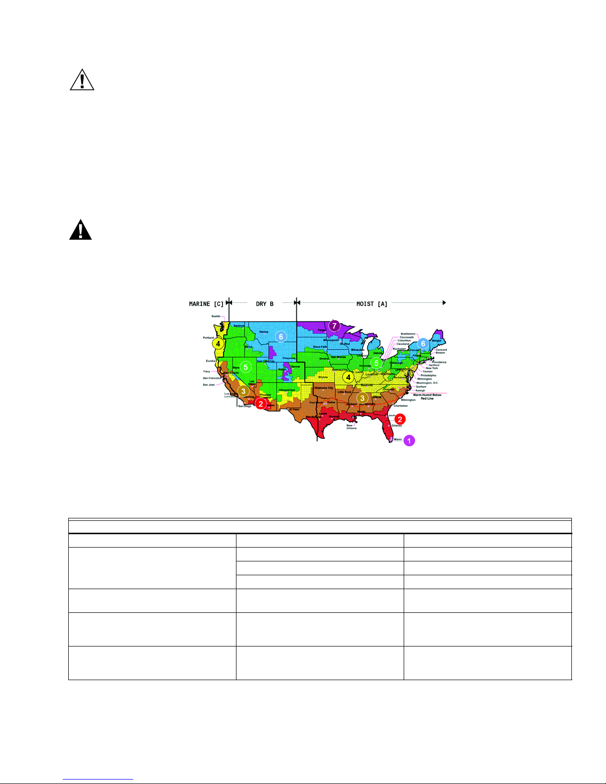
NOTICE
WARNING
Some economizer strategies are not applicable for all climates in the United States. ASHRAE Standard 90.1 - 2010
Table 6.5.1.1.3 A describes what economizer strategies should be used in various climate regions in the United
States. For example, the fixed enthalpy economizer strategy is not permitted in U.S. climate zones 1b, 2b, 3b, 3c,
4b, 4c, 5b, 5c, 6b, 7, and 8 and fixed dry bulb and differential dry bulb economizer strategy is not permitted in U.S.
climate zones 1a, 2a, 3a, and 4a.
Honeywell Integrated Economizer Control, Climate Zones, Getting
Tactical!
If outdoor air is cool enough, our integrated economizer system begins to control our outdoor air actuator to attempts to
control to mixed air set point. The control is mitigated by a throttling range set point.
Unless you are instructed to do so by your Honeywell or LCBS Connect control system distributor, you should
NEVER have to change mixed air set point and throttling range. Over 8M of the control systems we've
provided to the HVAC industry have these set points "hard coded" in the devices with literally no complaints,
callbacks, or service interventions.
Fig. 3.
Pacific Northwest National Laboratory & Oak Ridge National Laboratory August 2010
http://www1.eere.energy.gov/buildings/publications/pdfs/building_america/ba_climateguide_7_1.pdf
Table 2.
ASHRAE 90.1 PERMISSABLE ECONOMIZER CONTROL TYPES, HIGH LIMIT, CHAGEOVER OPTIONS
CONTROL TYPE ALLOWED IN CLIMATE ZONES HIGH LIMIT, CHANGEOVER SETPOINT
FIXED DRY BULB TEMP 1B, 2B,3B,3C,4B,4C,5B,5C,6B,7,8 OUTDOOR AIR TEMP > 75°F
5A, 6A OUTDOOR AIR TEMP > 70°F
1A,2A,3A,4A OUTDOOR AIR TEMP > 65°F
DIFFERENTIAL DRY BULB TEMP 1B, 2B, 3B, 3C, 4B, 4C, 5B,5C,6B,7,8 OUTDOOR AIR TEMP > RETURN AIR
FIXED ENTHALPY WITH FIXED DRY
BULB TEMP
DIFFERENTIAL ENTHALPY WITH
FIXED DRY
When the mixed air control system has captured all the cooling value from outdoor air it can, the system will begin to
augment that call for cooling with mechanical cooling. An integrated low limit is also offered.
ALL OUTDOOR AIR ENTHALPY > 28
ALL OUTDOOR AIR ENTHALPY > RETURN
TEMP
BTU/LB OR OUTDOOR AIR TEMP >
75°F
AIR ENTHALPY OR OUTDOOR AIR
TEMP > 75°F
11 31-00118EFS—01
Page 12

LCBS CONNECT SOLUTION
NOTICE
Honeywell Integrated Economizer Control - High Limit and Changeover
Strategies
North America features widely different climates. ASHRAE and other code bodies recognize this fact and provide control
guidance. These organizations drive application and use of economizer systems regionally. These different climate zones
drive different economizer application practices. For example, air in Honolulu and Miami is far hotter, higher dew point
and has almost no capability to be used to augment the HVAC cooling process.
As a service contractor, you probably know what your customer's needs are. Continue to set controls how you see
fit. We haven't seen any building code or ASHRAE police roaming any U.S. streets, yet!
The information below describes the use of the following economizer strategies.
Strategy 1: Differential Enthalpy with Fixed Dry Bulb Temperature Limit
This technique can be used in all ASHRAE climate zones. Successfully applied, excellent energy savings can accrue to
building owners. LCBS Connect remote services alerting and analytics can help you fine tune settings to maximize
customer energy savings and maintain comfort.
How does it work? If there is a call for cooling and return air enthalpy is less than outdoor air enthalpy and the outdoor air
temperature is below high limit, changeover set point, RETURN air will be used to cool your customer's building. If there is
a call for cooling and return air enthalpy is GREATER than outdoor air enthalpy and the outdoor air temperature is below
high limit, changeover set point, OUTDOOR air will be used to cool your customer's building.
Enthalpy hysteresis is adjustable to make sure that you don't experience excessive enabling and disabling of the
economizer cycle potentially overusing the economizer actuator. It is advised that you don't change this value unless you
talk to a Honeywell distributor or customer support professional.
Strategy 2: Outdoor Air Enthalpy
This technique can be used in all climate zones. HVAC professionals like this method as it's relatively simple to deploy. As
with all economizer limit and changeover strategies, LCBS Connect remote services alerting and analytics can help you
fine tune setting to maximize customer energy savings and maintain comfort. There is an ASHRAE prescriptive value
suggestion at 28 LB/BTU changeover. Many folks find this a bit warm and could result in customer, client comfort issues.
How does it work? If there is a call for cooling and outdoor air enthalpy is less than outdoor air enthalpy set point and the
outdoor air temperature is below high limit, changeover set point, outdoor air will be used to attempt to cool your
customer's building.
Again, enthalpy hysteresis is adjustable to make sure that you don't experience excessive enabling and disabling of the
economizer cycle potentially overusing the economizer actuator. It is advised that you don't change this value unless you
talk to a Honeywell distributor or customer support professional.
Strategy 3: Differential Temperature
This technique is suggested to be used in zones 1B, 2B, 3B, 3C, 4B, 4C, 5A, 5B, 5C, 6A, 6B, 7, and 8. See map on page 16.
HVAC professionals like this method as it's relatively simple to deploy and understand. As with all economizer limit and
changeover strategies, LCBS Connect remote services alerting and analytics can help you fine tune setting to maximize
customer energy savings and maintain comfort.
How does it work? If there is a call for cooling and outdoor air temperature is less than return air temperature and the
outdoor air temperature is below high limit, changeover set point, outdoor air will be used to attempt to cool your
customer's building. If there is a call for cooling and outdoor air temperature is GREATER than return air temperature and
the outdoor air temperature is below high limit, changeover set point, RETURN air will be used to attempt to cool your
customer's building.
Temperature hysteresis is adjustable to make sure that you don't experience excessive enabling and disabling of the
economizer cycle potentially overusing the economizer actuator. It is advised that you don't change this value unless you
talk to a Honeywell distributor or customer support professional.
Strategy 4: Outdoor Temperature
This technique is suggested to be used in zones 1A, 2A, 3A, 4A, 5A, 6A, 1B, 2B, 3B, 3C, 4B, 4C, 5B, 5C, 6B, 7, and 8. See map
on page 16.
31-00118EFS—01 12
Page 13

LCBS CONNECT SOLUTION
HVAC professionals like this method as it's probably the simplest strategy to deploy and understand. This technique was
widely used before humidity sensing technology became cost effective. As with all economizer limit and changeover
strategies, LCBS Connect remote services alerting and analytics can help you fine tune setting to maximize customer
energy savings and maintain comfort.
How does it work? If there is a call for cooling and outdoor air temperature is less than outdoor air temperature is below
high limit, changeover set point, outdoor air will be used to cool your customer's building.
Temperature hysteresis is adjustable to make sure that you don't experience excessive enabling and disabling of the
economizer cycle potentially overusing the economizer actuator. It is advised that you don't change this value unless you
talk to a Honeywell distributor or customer support professional.
Low Limit Temperature Override Control
HVAC coil protection is offered as a feature as part of integrated economizer control. Please note that this feature does
not work with the "simple" digital input, digital output economizer control sequence described above.
How it works. The low limit control overrides the economizer damper position to prevent the economizer control sensor,
mixed air temperature or discharge air temperature from falling below the low temperature override limit by closing the
economizer, outdoor air damper. The low limit temperature override control is disabled when DCV is enabled as heating
will allow to cycle on.
Freeze Stat Operation
The capability to apply and install an electromechanical freeze stat as an ultimate redundant control is available. Simply
select freeze stat function by configuring the appropriate digital input on the LCBS Connect controller. A freeze stat
contact must be installed and an output from the device needs to be terminated to the LCBS controller. If the freeze stat is
configured and the LCBS Connect controller input is closed, the CVAHU system will be shut down. The freeze stat
function can also be used to shut down the CVAHU system for smoke or fire alert, alarm.
Economizer Control Summary
LCBS Connect controllers feature an "ASHRAE Complete" range of economizer control, changeover, and
high limit options. If you are attempting to commission a "direct drive" economizer system, read this
description carefully. LCBS Connect remote services will be a great help to you as you fine tune economizer
control.
ADVANCED TEMPERATURE CONTROL FUNDAMENTALS
If you would like to learn how to "fine tune" control loops, you may want to take some time to learn about more advanced
control fundamentals. This will also be important for you if you chose to construct "Accessory Loops" as part of your
control business. Please read the following about proportional, integral, and derivative control operation. Contact your
Honeywell LCBS Connect professional for assistance.
Proportional Control and the Concept of Differential and Throttling Range
Let's start with basic control. Feedback control uses the "error", defined as the sensed value minus the set point, to
determine how to drive the output. Proportional Control commands the output as a direct proportion of the current error.
This is typically configured with a "Proportional Band" or a "Throttling Range" that defines the value of the error that will
result in the control output going to 100%. These terms are typical when we are describing modulating output. If we are
driving a digital output, the difference that is observed between the controlled load being energized and de-energized is
typically referred to as Differential.
So, if we are driving a modulating output, then the output is set to the percent calculated from the ratio of the error to the
Throttling Range (TR, e.g. if the error is ½ the TR, the output would be 50%, and if the error is equal to the TR then it would
be 100%).
Proportional Control
Proportional control is the function that determines the output setting required to meet the load conditions.
13 31-00118EFS—01
Page 14
LCBS CONNECT SOLUTION
THROTTLING
100%
80%
60%
40%
20%
0%
CONTROLLER OUTPUT %
70°F 72°F 74°F 76°F 78°F
EXAMPLE: COOLING – DIRECT ACTING
SETPOINT 72°F THROTTLING RANGE 4°F
RANGE
SENSOR INPUT VALUE
100%
80%
60%
40%
20%
0%
CONTROLLER OUTPUT %
70°F 72°F 74°F 76°F 78°F
EXAMPLE: HEATING – REVERSE ACTING
SETPOINT 76°F THROTTLING RANGE 4°F
THROTTLING
RANGE
SENSOR INPUT VALUE
MCR36698
Fig. 4.
A direct acting control loop is one where the output increases as the input sensor value rises above the set point. A reverse
acting control loop is one where the output increases as the input falls below the set point. Direct or reverse acting should
be selected based on the application requirements with the consideration that set point is the "no load" value of the
measured variable and with 0% output the energy input should be the closed or off. The physical outputs can be
configured to match the controlled devices (normally open, normally closed, energized on, energized off, etc.).
APPLICATION EXAMPLES
DIRECT ACTING. CONTROL DEVICE INCREASES AS
MEASURED VALUE INCREASES
REVERSE ACTING. CONTROLLED DEVICE DECREASES
AND MEASURED VALUE INCREASES
COOLING STATIC PRESSURE HEATING LIGHTING
DEHUMIDIFICATION CHILLED WATER PUMP HUMIDIFICATION STATIC PRESSURE
MIXED AIR CONDENSER WATER PUMP HOT WATER PUMP
The proportional calculation determines proportional error (Ep). Proportional error is the deviation from set point of the
sensed medium (input sensor) divided by the throttling range expressed in units of the input sensor. The set point is the
value of the input sensor at which the control loop is satisfied. When the input sensor value is at set point there is no
proportional error and the output is 0%. The throttling range is the amount of change in the sensed medium required to
drive the output from 0 to 100%. By definition, in proportional control the input value must deviate from set point to
initiate a change in the output.
Selected Throttling Range must be narrow enough to provide good control without becoming unstable. The throttling
range is determined by a number of factors such as the control application, the response time to the equipment being
controlled, and the control algorithm being used. The narrower (smaller) the throttling range, the more precise the control
and the wider (larger) the throttling range, the more stable the control. The objective is setting the throttling range to
achieve the optimum balance between precision and stability.
Set point and Differential Refresher - On Off, Digital Control
The following is a refresher course for you and describes the relationship between set point and differential for heating
and cooling. These settings are typically programmed for each control loop and each on off output.
In heating mode, the differential is below the set point. The output relay de-energizes when the temperature rises to the
set point. As the temperature drops to the set point minus the differential, the relay energizes. You will also see this
referred to as "direct acting," where increased control action is in direct relationship to increased temperature value.
31-00118EFS—01 14
Page 15

LCBS CONNECT SOLUTION
PROPORTIONAL ON OFF CONTROL HEATING (REVERSE ACTING)
TYPICAL HEATING CIRCUIT
LOAD (HEATING) ON
“ERROR” =
SETPOINT PLUS
MEASURED
VALUE
HEATING
SETPOINT
“ON” WHEN “MEASURED VALUE” REACHES SETPOINT, OFF WHEN
“SETPOINT” PLUS “DIFFERENTIAL” EQUALS “MEASURED VALUE.”
REPEAT AS LOAD CHANGES.
LOAD (HEATING) OFF
MCR36699
LOAD
(HEATING) ON
PROPORTION AL CONTROL
– HEATING – REVERSE ACTING
MEASURED VALUE
“DIFFERENTIAL
PROPORTION AL ON OFF CON TROL COOLIN G
(DIRECT ACTING) TYPICAL COOLING CIRCUIT
MEASURED VALUE
LOAD (COOLING) ON
LOAD (COOLING) OFF
“DIFFERENTIAL
“ERROR” =
SETPOINT
LESS
MEASURED
VALUE
COOLING
SETPOINT
PROPORTIONAL CONTROL – COOLING – DIRECT ACTING
“ON” WHEN “MEASURED VALUE” REACHES SETPOINT, OFF WHEN
“SETPOINT” LESS “DIFFERENTIAL” EQUALS “MEASURED VALUE.”
REPEAT AS LOAD CHANGES.
MCR36700
Fig. 5.
In cooling mode, the differential is above the set point. The output relay de-energizes when the temperature falls to the
set point. As the temperature rises to the set point plus the differential, the relay energizes. You will also see this referred
to as "reverse acting, where increased control action is in direct relationship to reduced temperature value.
Integral Action Primer and Refresher Course for Some
The purpose of the integral function is to eliminate the offset inherent in proportional control, in other words, integral
control functions to hold the input sensor value at set point.
The integral function is a function of proportional error and time.
When the proportional error is greater than 0 the integral error will be calculated and added to proportional error to
determine the control loop output. The integral error is cumulative and will continue to increase as long as the
proportional error is greater than 0. The increase in the output signal will drive the controlled device further open and the
controlled medium will be brought closer to set point. While the proportional error is reduced, the integral error will
continue to increase until the proportional error is eliminated.
Fig. 6.
15 31-00118EFS—01
Page 16

LCBS CONNECT SOLUTION
NOTICE
T0 T1 T2 T3 T4
PROPORTIONAL PLUS INTEGRAL CONTROL
EI = INTEGRAL ERROR
EP = PROPORTIONAL ERROR
V=TOTAL ERROR IMPACT, P PLUS I
OUTPUT
%
100%
80%
60%
40%
20%
0%
THROTTLING
RANGE
INPUT
SENSOR
DEGREES F
80°F
75°F
70°F
SETPOINT
V=EI + E
P
E
P
E
I
MCR36701
Fig. 7.
When the proportional error equals 0 the calculated integral error is 0 and no change is made to the output.
When the proportional error is less than 0 the integral error is calculated as a negative value resulting in decrease in the
integral error.
The integral time value is set in seconds based on the lag time of the controlled process. A slow process such as space
temperature control requires a long integral time (600 seconds or more) while a fast process such as static pressure
control requires a short integral time. An integral time value of 0 (default) eliminates implementation the integral
function.
P+I control can decrease stability of a control loop. Stability of the control loop is a balance of the throttling range and the
integral time. If a P+I control loop is unstable it is necessary to increase the throttling range and/or increase the integral
time. In general, the throttling range required for P+I control is greater than that for proportional only.
A bit of good news. Honeywell has utilized "proportional plus integral control" in analog and digital temperature
control devices for residential and commercial customers for 40 years. LCBS Connect controllers are
preconfigured with proper settings as they have been for 40 years. You simply don't have to do a thing to take
advantage of this sophisticated control.
If you decide to use LCBS Connect controller "accessory loop" function, you may want to ask your Honeywell LCBS
Connect distributor for a hand. If you decide to control something other than temperature with the accessory loop
function, you may need to provide integration timing factor. For example, if you want to control outdoor lights, the
integration feature doesn't add to the quality of control and the integration timer should be set to zero (0). Simple set
point and differential are the only parameters that need to be set.
Do You Want to Know More about Integral Control?
As a starting point, the LCBS Connect controller uses the dependent gains form of the PID equation. This means that you
specify an integral time and the actual integration gain is dependent on the Throttling Range (TR). Specifically the
integral time is the time in seconds that it should take for the integration result to be 100% if the error is held constant at
the TR. For room control integral time typically ranges from 1,000 to 2,500 seconds given the standard throttling range
used. Note that the LCBS Connect controller integral gain for the thermostat function is predefined for optimal
performance and should generally not be changed! The purpose of integral action is to reduce the offset from set point
during steady state control that can be experienced using proportional only control. Again, as general information,
control action is impacted by throttling range selection and adjustment. It's a good idea to adjust the throttling range first
before making any adjustment to integral time. It's a good idea to adjust throttling range to be as wide as possible
because this will provide the most stable control. Remember that the integral will eliminate the steady state error so you
do not need to have a small throttling range to have accurate control. Integral action allows for controlling to set point
even with a wide throttling range.
31-00118EFS—01 16
Page 17

LCBS CONNECT SOLUTION
Derivative Control
Proportional-integral-derivative (PID) control adds the derivative function to PI control. The derivative function opposes
any change and is proportional to the rate of change. The more quickly the control point (actual sensed temperature)
changes, the more corrective action the PID system provides. The higher the derivative setting, the greater the effect. In
LCBS Connect controllers, the derivative default value is factory set to zero resulting in no control. It is strongly
recommended that the derivative remain at zero (0) unless you have a very good reason to adjust it. Derivative
control is not needed in the vast majority of HVAC applications.
DEMAND CONTROLLED VENTILATION
Theory and Operation Demand Controlled Ventilation (DCV).
As energy costs increased in the last half of the 20th century, coupled with the cost of providing ventilation to building
spaces during height and depth of winter and summer, ventilation codes have been altered. It is acceptable to supply
ventilation at a rate equivalent to the number of building occupants as opposed to a fixed minimum ventilation rate of
outdoor air actuator and dampers.
DCV Operation
As energy consumption continues to be a driving part the economics to operate HVAC systems, we continue to support
HVAC strategies that will allow systems to dynamically "decrease" fresh air ventilation rates if there are a few occupants in
a building space. Unfortunately, many building owners and operators have figured this out and have purposefully
restricted fresh air ventilation flow to building occupants. Incorrectly executed, this can result in sluggish behavior and
illness directly caused by stale, recirculated air.
Without writing an HVAC physics paper, scientists have determined that the presence of carbon dioxide gas is
proportional to oxygen content in air due to human respiration. Fact is that the "primary function (of human respiration)
is to obtain oxygen for use by body's cells and eliminate carbon dioxide that cells produce." The less content of carbon
dioxide in the air, the less presence of human respiration (and humans) exists. This makes people drowsy, ill, and worse.
Find levels and associated human impact of CO2 in confined building spaces provided by "Engineering Tool Box:"
SITUATION CO2 PPM LEVELS
NORMAL OUTDOOR AIR PPM LEVEL 350-450 PPM
ACCEPTABLE PPM LEVEL <600 PPM
COMPLAINTS OF DISCOMFORT, ODORS BY BUILDING OCCUPANTS 600-1,000 PPM
ASHRAE AND OSHA STANDARD, EXPECTATION 1,000 PPM
GENERAL DROWSINESS 1,000-2,500 PPM
ADVERSE HEALTH EFFECTS EXPECTED 2,500-5,000 PPM
MAXIMUM ALLOWED CONCENTRATION WITHIN AN EIGHT (8) HOUR WORKING
PERIOD
Source: http://www.engineeringtoolbox.com/
The Honeywell LCBS Connect control can reduce ventilation in a building space with feedback from a CO2 sensor. As you
can see from the table above, it is desirable to keep interior building space CO2 levels at 1,000 PPM or below during
building occupancy periods. If sensed CO2 level falls, it is acceptable to reduce outdoor air damper minimum position
and still conform to building code. The LCBS Connect controller will reduce outdoor air damper position until sensed CO2
begins to rise. Again, if it is very cold or very warm outdoors, reducing outdoor air position can save substantial negative
energy consumption and associated cost outlay.
5,000 PPM
First "law" of ventilation
The bigger the rate is, the more my energy bills will be. The more extreme the climate, the more damaging high rates of
ventilation are. So, what if I only have five (5) people in my building, instead of 20? I only need to provide 50 CFM of fresh
air to the building. As a building owner I could do two things. First, if I could control to this lower level and I could 1]
provide appropriate fresh air to my building guests and 2] save a bunch of energy dollars by backing off ventilation rate.
Demand Controlled Ventilation (DCV) unlocks the promise of dynamically provide lower ventilation rates automatically
and delivering benefits described above.
17 31-00118EFS—01
Page 18

LCBS CONNECT SOLUTION
How do we do this?
Do I count folks as they come in and out of the controlled building space? There are a few promising technologies that
could "count people," but they simply aren't economical now. The preferred method to sense guest's presence in an
enclosed space is the detection of CO2 gas and associated sensing technology. Because this isn't a science lesson, we'll
be humane. Simply put, human beings breathe in oxygen and as our body processes oxygen and the other things we
consume, we "exhaust" and exhale CO2. CO2 is far from fatal if continually ingested by the human body, but it does make
us sleepy, grumpy, and less attentive. Again, not a science lesson, but we also refer to CO2 as a "trace gas." What is this?
Consider carbon dioxide and "proxy" for other nasty stuff in building environment. Simply put, there are other noxious by
products floating in the air including VOCs (outgassed from carpeting, paint, cleaning solutions) and bugs that float
around from folks coughing and sneezing. Just to be clear, when we refer to "cold and flu season," one of the contributing
factors of this phenomenon is bad building ventilation.
DAMPER POSITION
MINIMUM DCV
VENTILATION
DAMPER
POSITION
MINIMUM
VENTILATION
DAMPER
POSITION
DCV
SETPOINT
DCV
SETPOINT
+ 100 PPM
SPACE CO2 LEVEL
MCR36702
Fig. 8.
Providing good ventilation is important. Let's go back to the theory and operation of DCV. During building occupancy, we
continuously and dynamically sense CO2. If the level of CO2 is lower than our selected threshold, or "limit," we control rate
of ventilation at the "minimum ventilation damper position" level. Theoretically, this is a position that will provide fresh air
to estimated building occupant population as we've discussed before.
Let's add a factoid here. HVAC "scientists" suggest that at 800 PPM building CO2, bad things start happening to the
human being as we've shown. This becomes a typical and suggested setting to monitor and control carbon dioxide
content in our building space. Our automatic control system begins to reset minimum ventilation rates from our
"minimum ventilation damper position" level to our "minimum DCV ventilation damper position." This reset will
dynamically continue based on sensed carbon dioxide PPM level in the space.
Demand Controlled Ventilation Summary
LCBS Connect controllers can provide mitigation strategy based on the increase of CO2 as a "trace gas"
indicating the fouling of oxygenated air. As described, this results in "woozy" building occupants and can
also lead to illness as described in this document. As with previous control loops, there are many values that
you can alter that will make your DCV strategy work well or work badly. It is essential that you understand 1] what DCV
techniques you and your company likes to use and 2] what the prevailing building code, ventilation standard is for your
area.
ADAPTIVE INTELLIGENT RECOVERY
Adaptive Intelligent Recovery is a Honeywell is a patented feature that when properly applied 1] ensures comfort for
building occupants at occupancy even after equipment has been controlled at a higher (cooling) or lower (heating)
temperature after hours 2] gradually ramps set points up or down (heating or cooling) reducing wear and tear on
equipment and 3] reduces the likelihood of all equipment cycling at the same time that could result in undesirable high
electrical demand.
LCBS Connect controllers use Adaptive Intelligent Recovery to gradually and dynamically transition temperature
setpoints from unoccupied to occupied, standby to occupied, and unoccupied to standby operation. The concept of
Adaptive Intelligent Recovery is to gradually increase or decrease (heating, cooling) the set point from the unoccupied or
standby set point, to the standby or occupied set point over a period of time to match the recovery capability of the
mechanical system, providing benefits listed above.
31-00118EFS—01 18
Page 19

LCBS CONNECT SOLUTION
NOTICE
MCR36722
OUTDOOR AIR TEMPERATURE – RECOVERY SENSOR VALUE
MINIMUM (MIN)
RECOVERY RAMP RATE
(DESIGN LOAD)
OUTDOOR AIR TEMPERATURE
INDICATING DESIGN
COOLING CONDITION
UNOCCUPIED OR
STANDBY SETPOINT
MIN
MAX
START “OCCUPIED”
SCHEDULE
STANDBY OR
OCCUPIED SETPOINT
MAXIMUM (MAX)
RECOVERY RAMP RATE
(NO LOAD)
OUTDOOR AIR TEMPERATURE
INDICATING LOW, NO LOAD
CONDITIONS
The minimum ramp rate assures that the occupied temperature will be met at the appropriate scheduled occupied time
without overheating or overcooling condition space. If the equipment is oversized or the call for mechanical cooling or
heating is not too severe, the equipment is cycled appropriately to achieve occupied set point in a timely manner. The
beneficial outcome is gradual, responsible operation of equipment that ultimately saves energy, reduces wear and tear on
equipment, and ensures comfort conditions by occupancy.
Similarly, the maximum ramp rate assures that the occupied temperature will be met at the appropriate scheduled
occupied. In this case, it's probably very hot, very cold outside or some type of excessive load exists in the building space.
Maximum ramping is probably associated with observation and realization of local heating or cooling "design
conditions." As with minimum ramping, the beneficial outcome is the same including responsible operation of equipment
that reduces wear and tear on equipment and ensures comfort by occupancy.
Work with your Honeywell customer service or Honeywell LCBS Connect distributor professional for advice
for constructing parameters properly to ensure successful Adaptive Intelligent Recovery deployment.
SETPOINT NAME DESCRIPTION
MINIMUM RECOVERY
SENSOR VALUE
MAXIMUM RECOVERY
SENSOR VALUE
MINIMUM RECOVERY
RATE
THE VALUE OF THE RECOVERY SENSOR (TYPICALLY OUTSIDE AIR AT LOCAL DESIGN
TEMPERATURE) AT WHICH THE MINIMUM RECOVERY RAMP OCCURS.
THE VALUE OF THE RECOVERY SENSOR (TYPICALLY OUTSIDE AIR AT NO LOAD
TEMPERATURE) AT WHICH THE MAXIMUM RECOVERY RAMP OCCURS.
THE RECOVERY RATE FOR THE MECHANICAL SYSTEM (TYPICALLY HEATING OR COOLING)
AT DESIGN CONDITIONS (USUALLY THE OUTSIDE AIR TEMPERATURE). THIS MINIMUM RATE
OF RECOVERY TAKES THE MAXIMUM TIME TO GET TO THE NEW OCCUPIED OR STANDBY
SETPOINT.
MAXIMUM RECOVERY
RATE
THE RECOVERY RATE FOR THE MECHANICAL SYSTEM (TYPICALLY HEATING OR COOLING)
AT NO LOAD CONDITIONS (USUALLY THE OUTSIDE AIR TEMPERATURE AT WHICH HEATING
OR COOLING IS NO LONGER NEEDED). THIS MAXIMUM RATE OF RECOVERY TAKES THE
MINIMUM TIME TO GET TO THE NEW OCCUPIED OR STANDBY SETPOINT.
NOTE: When used with Adaptive Intelligent Recovery, minimum and maximum apply to the rate of recovery expressed in
degrees per hour. The smallest amount of recovery in one hour is minimum recovery. The most recovery in one
hour is maximum recovery. For example, a heating plant can be sized for a recovery of 3°F per hour, at 0°F outside air temperature and a recovery of 8°F per hour at 55°F. The minimum recovery rate is 3°F per hour and the
maximum recovery rate is 8°F per hour.
Adaptive Intelligent Recovery™ Summary
You will need to understand how your equipment is sized in relationship to heating and cooling load in the
middle of summer and winter and during transitional climate season. It is absolutely essential that you
understand concepts in diagram above so that you can commission an effective recovery strategy. Use LCBS
Connect remote troubleshooting tools to help you set appropriate Adaptive Intelligent Recovery settings.
Fig. 9.
Table 3.
19 31-00118EFS—01
Page 20

LCBS CONNECT SOLUTION
MULTISPEED FAN
Multispeed Fan Theory and Operation. Almost 80% of the commercial heating and air conditioning systems in North
America feature a one speed, single speed fan. Rising energy costs, accompanied by increasing HVAC mechanical system
expertise and technology have given rise to the concept to alter the speed of a supply fan during occupied building hours.
A typical HVAC system is sized for regional, geographic "design conditions" at a certain rate of compliance. For example,
in Birmingham, Alabama, find metrological design facts of interest:
HEATING DB °F COOLING DB/MCWB °F/°F
DB WB DB WB
STAT ION LAT LON EL EV
BIRMINGHAM
MUNICIPAL AIRPORT
*Exceeds parameter, criteria N% of observed climatological condition.
As you know, commercial HVAC equipment is sized to operate at its full capacity limit at some percent level of design,
local climate condition. In Birmingham, an HVAC unit operates at full capacity when it's equal or above 95°F dry bulb and
75.1°F wet bulb outdoor temperature, further at the 99.0% design level. Specifically, this means that 99% of the time, the
HVAC unit operates at a LOWER load level. Bottom line, there is plenty of opportunity to mitigate, reduce air flow, thus
reduce operational supply fan speed. As you know, this is one of the basic tenets of "variable air flow" design and there is
no reason why we can't deploy load reduction principles to constant volume air handling units.
33.56N 86.75W 630 19.6 24.0 95.0 75.1 92.6 74.9
Multispeed Fan Operation
Honeywell LCBS Connect controller offers a variety of control strategies to control fan speed. Industry sources have
shown that varying supply fan speed can result in substantial energy and O&M savings by engaging the technique.
99.6%* 99.0%* 99.6%* 99.0%* 99.6%* 99.0%*
There are three basic ways that we can achieve this applying LCBS Connect control system. First, a traditional belt drive
single-speed motor controlled by a variable frequency drive (VFD) can be used, second, a two-speed motor with two sets
of preset motor windings, and lastly a direct-drive motor (PSC or ECM) controlled by relays or a digital control system.
Two speed motor
The two-winding, two-speed motor is the simplest of the three options that the LCBS Connect controller can control. The
motor will have two sets of windings; this motor is typically provided by an HVAC OEM or by a motor supplier directly. One
set is energized for one discrete speed and the other set energized for the second discrete speed. If you encounter a motor
like this, it is already wired to control the two discrete speeds with LCBS Connect controller. Again, note that the speeds
are probably unchangeable in the field.
VFD application
The LCBS Controller sends a control signal to a VFD that changes frequency and the speed of the supply fan motor. LCBS
Controller supports up to six discrete speeds. Each of the speeds can be assigned to a specific control "mode," like
"ventilation, stage 1 cooling, stage 2 - 3 cooling, stage 1 heating," and so on. Please note that if you are considering
retrofit of a motor, that motor bearings are able to support operation at less than the 60 Hz design speed. Cost of VFDs
have decreased over the years, they are efficient, and they can be preprogrammed to specific speeds. Because of their
electrical construction, VFDs can gradually increase supply fan speed, providing supply fan "soft start." This avoids
starting jolts that create excess noise and mechanical wear on the system.
Direct drive "ECM" motor
A direct-drive motor can received a control signal from the LCBS Controller that will change the supply fan motor speed.
You will find that these are typically low horsepower applications, usually found is system less than five (5) tons. You will
find that the direct-drive motor takes up no additional space in the base rooftop and can be field configured through the
LCBS Controller.
LCBS Connect can perform all currently accepted multispeed supply fan strategies. If you encounter an ECM type supply
fan motor or two speed, two winding fan, we can control it. For retrofit application, it is our recommendation that the
application of a VFD makes most sense. It provides ultimate ability to alter supply fan motor speed and provides soft start
operation for the fan motor. Make sure you are conscious of application of a VFD with the motor you are attempting to
control.
31-00118EFS—01 20
Page 21

LCBS CONNECT SOLUTION
WARNING
Honeywell LCBS offers two basic multispeed control options. They are:
— Two speed, discrete fan control.
— Multispeed variable-constant fan control, up to six stages of fan.
Two Speed Discrete Fan Control
In a two-speed discrete fan supply strategy, the fan SPEEDS must be able to be operated and controlled in a discrete
manner. Specifically, there are two outputs on the LCBS Connect controller that controls "Fan Low Speed" and "Fan High
Speed." The two-winding, two-speed motor is the simplest of the three options that the LCBS Connect controller can
control. The motor will have two sets of windings. One set of windings is energized for one discrete speed and the other
set is energized for the second speed. If you encounter a motor like this, it is probably already wired to control the two
discrete speeds to existing control system.
NOTES:
1. Speeds are probably unchangeable in the field as they are "hardwired" by the motor manufacturer.
2. If you are replacing a control system with the LCBS Connect controller, the HVAC system may "hide" the complexity of control of the two speed fan and actually allow the service contractor to apply a standard staged
heating, staged cooling, fan with two speed logic performed on the line voltage side of the control system. A
typical way a fan is controlled on a 3 - 25 ton constant volume air handling unit is low speed as follows that
DOES NOT require two speed control interface and just a simple R,G,W,Y thermostat. Please refer to this
sequence to understand this point:
Table 4.
OCCUPANCY
CONDITION
UNOCCUPIED NO CONTROL SYSTEM VOLTAGE, NO CALL FOR
TRANSITION
FROM
UNOCCUPIED TO
OCCUPIED
OCCUPIED, NO
CALL FOR
COOLING
OCCUPIED, CALL
FOR COOLING
OCCUPIED, CALL
FOR HEATING
LOW VOLTAGE INTERFACE, WHAT THE
EXISTING THERMOSTAT DOES
HEATING OR COOLING.
NO CONTROL SYSTEM VOLTAGE, FAN CIRCUIT
(G) ENERGIZED W (CALL FOR HEAT) Y (CALL
FOR COOL).
CONTROL SYSTEM VOLTAGE PRESENT, FAN
CIRCUIT (G) ENERGIZED.
CONTROL SYSTEM VOLTAGE PRESENT, Y (CALL
FOR COOLING) FAN CIRCUIT ENERGIZED.
CONTROL SYSTEM VOLTAGE PRESENT, W
(CALL FOR HEATING) FAN CIRCUIT ENERGIZED.
HOW SYSTEM IS CONTROLLED, LINE
VOLTAGE
CONTROL SYSTEM FEATURES A TIMING
FUNCTION TO TURN OFF 24 VAC.
24 VAC TOGGLES FROM OFF TO ON, Y AND W
CYCLE WITH LOW SPEED FAN WINDING.
24 VAC ON, PROVIDES VOLTAGE TO
ECONOMIZER AND LOW SPEED FAN WINDING.
24 VAC ON, PROVIDES VOLTAGE TO
ECONOMIZER AND HIGH SPEED FAN WINDING.
24 VAC ON, PROVIDES VOLTAGE TO
ECONOMIZER AND HIGH SPEED FAN WINDING.
If the constant volume control system controls a system as shown above, do NOT use the two fan speed logic
provided by LCBS controller.
Two Speed and Multispeed VFD Application
The LCBS Controller sends a control signal (0-10 VDC) to a VFD that changes frequency and the speed of the supply fan
motor.
NOTES:
1. Consult with VFD manufacturer to ensure that the supply fan motor in your constant volume air handling unit
is able to be controlled by the VFD. As time goes on, older technology motors in typical 3 - 25 constant volume
air handling units become ever less applied, but care must be taken retrofitting motors.
2. While changing the speed of a fan motor can yield excellent energy savings, the service contractor must take
care to ensure that reduced air flow is substantial to dissipate heat or cool load across the heat exchanger. If
airflow is dropped to severely, damage to heating or cooling equipment can occur, not to mention reduced
comfort conditions.
21 31-00118EFS—01
Page 22

LCBS CONNECT SOLUTION
TIME
100
90
80
70
60
50
40
30
20
10
0
FAN SPEED (GRAY BAR)
TEMPERATURE (GRAY LINE)
SINGLE
HEAT
VENT
OFF
FAN SPEED
HEATING SETPOINT
MCR36671
SINGLE
HEAT
COOLING SETPOINT
SINGLE
COOL
MULTISTAGE
COOL
As mentioned above, cost of VFDs have decreased over the years, they are efficient, and they can be preprogrammed to
specific speeds. Because of their electrical construction, VFDs can gradually increase supply fan speed, providing supply
fan "soft start." This avoids starting jolts that create excess noise and mechanical wear on the system
Electronic Direct Drive Motor (ECM, et al.) A direct-drive motor can received a control signal from the LCBS Controller
that will change the supply fan motor speed. You will find that these are typically low horsepower applications, usually
found is system less than five (5) tons. You will find that the direct-drive motor takes up no additional space in the base
rooftop and can be field configured through the LCBS Controller.
LCBS Connect can perform all currently accepted multispeed supply fan strategies. If you encounter an ECM type supply
fan motor or two speed, two winding fan, we can control it. For retrofit application, it is our recommendation that the
application of a VFD makes most sense. It provides ultimate ability to alter supply fan motor speed and provides soft start
operation for the fan motor. Make sure you are conscious of application of a VFD with the motor you are attempting to
control.
How it Works VFD Application and Direct Drive "ECM" Motor
The LCBS Connect controller offers some groundbreaking control technology to take advantage of ever lower costs of
variable frequency drives. The Honeywell approach permits the applier to assign any fan speed to any heating, cooling,
ventilation mode. The following table shows the options for VFD control.
Table 5.
CONTROL CONDITION
ENCOUNTERED, MODES DESCRIPTION
VENTILATION MODE NO CALL FOR HEATING, COOLING DURING OCCUPANCY 40-100%.
SINGLE STAGE HEATING CALL FOR ONE STAGE OF HEATING 40-100%.
MULTIPLE STAGE HEATING CALL FOR ONE, TWO, THREE STAGES HEATING 40-100%.
SINGLE STAGE COOLING CALL FOR ONE STAGE OF HEATING 40-100%.
MULTIPLE STAGE COOLING CALL FOR ONE, TWO, THREE STAGES HEATING 40-100%.
OTHER MODE DESCRIBE, DEFINE ANOTHER MODE 40-100%.
UP TO SIX FAN
SPEED CHOICES
Example of VFD Fan Control
Let's assume that I want to reduce fan speed during single stage of heat and ventilation mode at the same low rate 40%. I
want to reduce fan speed during first stage cool to 60%. I want the fan to run at 80% for multistage heat and cool HVAC
modes. Please refer to the diagram below to describe how we want the system supply fan will work.
Following the diagram from left to right, just above and to the left, note that if there is a call for "unoccupied heat," the fan
cycles on with the call for single stage heat, per single heat mode at 40%. When the call for heat abates, the fan cycles off
during "unoccupied" period. During Intelligent Recovery, call for heat occurs again and fan is energized to 40% speed, per
"single heat" mode. When system enters "occupied mode," fan speed is programmed for 40% and fan runs at this level. We
assuming that economizer carries the cooling load within "vent mode" and fan continues to run at 40%. We have a call for
mechanical cooling. When first stage of cooling is energized, fan runs at 60%. The call for cooling continues and second
state of cooling is energized. Per "multistage cooling" mode requirement, fan runs at 80%.
Without "multispeed fan" and variable frequency drive application, the fan operates as shown, to your left. The "yellow
area" indicates energy saving potential by running the fan with the Honeywell LCBS Connect controller algorithm.
Wow!
31-00118EFS—01 22
Fig. 10.
Page 23

YELLOW AND GRAY AREA = NO LCBS
Example
100
CONNECT CONTROL
90
80
70
60
50
40
30
20
10
0
MCR36703
FAN SPEED (GRAY AND YELLOW BAR)
FAN ON, OFF UNOCCUPIED, OCCUPIED MODE
ON
OFF
100%
COOLING SETPOINT
HEATING SETPOINT
FAN SPEED
TEMPERATURE (GRAY LINE)
TIME
ON 100%
Fig. 11.
Multispeed Fan Summary
Please take the time to understand the physics of the fan(s) you intend to control; wire them up properly and
determine how you are going to control them. It is essential that you read and understand the theory and
operation of the multispeed fan options and how you intend to control them. It is absolutely essential that
you understand concepts shown above so that you can commission an effective fan control strategy.
Contact your Honeywell LCBS Connect sales and support professional for assistance.
THEORY AND OPERATION ACCESSORY LOOPS
LCBS CONNECT SOLUTION
One of the key differences between residential and commercial applications is the presence of HVAC equipment, along
with commercial constant volume air handling units, rooftop units, and split systems. Vestibules, entry ways have unit
heaters, perimeter zones have electric and hot water radiant heaters, stock and storage rooms have unit heaters. All of
these HVAC types can be controlled by the LCBS Connect controllers. Lighting and refrigeration systems can also be
controlled by Accessory Loops. As long as we pay careful attention to HVAC and electrical physics of controlled loads, we
can do a great job of controlling most HVAC and other ancillary heating, cooling, and lighting loads.
How do Accessory Loops work?
For all intents and purposes, if you understand and can define inputs and outputs do in the control sequence, you will be
able to duplicate it with an LCBS Connect accessory loop. Two common examples that will demonstrate the use of LCBS
Connect accessory loops will be described. First will be a simple blower fan and gas heater, typically found in warehouses,
loading docks, stocking areas. Second will be a photocell loop that is commonly applied to turn outdoor lighting on and
off based on outdoor ambient light level.
Heating Blower Coil
Assume that a heating blower coil is in a loading dock and that the dock is open from 6 AM in the morning to
midnight. Because this is a heating blower coil, our primary requirements during occupancy would be 1] the
comfort of the loading dock employees and 2] good even temperature control. During unoccupied times from
midnight to 6 AM, out primary requirement is keeping pipes, product, and equipment from freezing in the
loading dock, warehouse area.
Setting up the application
First, a sensor should be selected in the controlled space proximate to the blower coil. The desired control set point range
should be considered in the selection process. Let's assume that we want to control the temperature in the loading dock
at 65°F during occupancy and we want to control the temperature in the loading dock during unoccupied time at 40°F. It
is desirable to ensure that blower coil is not over cycled, so choose the type to be a Staged Thermostat that will ensure
standard cycling behavior. Further we will configure, the PID action to be reverse acting (heating). This drives the
selection of the right room, space, zone sensor, type and action. We'll pick the TR40 sensing only device that has a range
from 32°F to 110°F. Secondly, we need to determine how to operate the control circuit to energize and reenergize the
blower coil fan and the gas or electric heating circuit. We need to examine the rating of the on-board relay on the LCBS
Connect controller. After brief investigation, we find that we can control a 1.0 A circuit at 24 VAC. This stated, we can
probably interrupt a low voltage control circuit directly or provide a line voltage relay with a low voltage relay coil.
NOTE: If you are controlling a line voltage load (110 VAC+) you need to provide a relay with an appropriate low volt-
age coil to control the control load.
23 31-00118EFS—01
Page 24

LCBS CONNECT SOLUTION
Example
Outdoor Ambient Lighting
The application is the control of outdoor lighting loads, using a sensor in the outdoors, measuring light level of
outdoor ambient light, typically "foot-candles," and turning external lighting on and off. To be clear, external
light circuits will be turned on as outdoor ambient light level decreases and off as light level increases. This loop
will remained enabled 24 hours a day to permit external lights to be on in the event of dark, gloomy days and will
be on to enhance safe condition outside our building.
Setting up the application
To control outdoor ambient lighting, several basics need to be considered. First, an outdoor rated ambient lighting sensor
must be selected. These devices typically feature physical rating and mounting kit that will permit outdoor use. It is
important to follow instructions relating to how the sensor is "aimed" at the light source. Second, the control output of
these sensors need to match LCBS Connect controller rating; 0-10 VDC should be selected. Finally, these systems need
DC power. Make sure the 20 VDC power supply from LCBS Connect controller has enough current to power the sensor.
This is particularly critical if you've applied more than one sensor per LCBS Controller that needs power. Next, we need to
determine how to operate the lighting circuit to turn lighting load on and off. As with the previous application, we need to
examine the rating of the on-board relay on the LCBS Connect controller. As we now know, we find that we can control a
1.0 Amp control circuit at 24 VAC. If our customer is using a circuit breaker panel (highly risky, poor practice, dangerous)
or line volt switches to turn lighting on and off, one or more low voltage coil relays with appropriately sized line voltage
relay contacts will be required. For this application we will choose type as "Staged Conventional" and the PID action to be
"Indirect".
In summary, Accessory Loop control provides a creative way to automatically control a wide variety of electric consuming
equipment in a commercial building.
Accessory Loops Summary
You will need to clearly understand are going to control a "controlled device," how it is going to act in
response to a change in the measured value, and what you want the output to be. Further, if you are using
custom sensors, you need to know how the media you are monitoring responds to the media. The Accessory
Loop is debatably one of the most clever and capable control strategy that we supply with LCBS Connect
controllers, but it take commensurate planning. So, if you going to deploy a "roll your own" temperature, humidity,
pressure, lighting strategy, you will need to go to print them out, and write out the settings and parameters you want to
implement. Go to LCBS Connect wall module or LCBS Connect Remote User Interface and input desired values. It is
absolutely essential that you understand concepts that are presented above so that you can commission an effective
"accessory loop" strategy.
SERVICE ALERTING THEORY AND FUNDAMENTALS
As fuel costs have increased in the last half of the 20th Century and the first part of the 21st Century, coupled with the
cost of providing professional service to our HVAC service customers, the use of remote services to inform service
providers of improper HVAC operation has become more and more popular. Building owners also realize that faced with
the challenge of keeping their employees, patrons, and guests comfortable coupled with rising energy costs that it's
simply good business to employ HVAC service contractors who use remote technology to oversee and service their
buildings. As ubiquitous remote technology including processing capability and storage grow and are enhanced,
Honeywell has harnessed "LCBS Connect Cloud Technology" and discovered a way to analyze data extracted from HVAC
systems in light commercial buildings and create meaningful service information. This information can be used by
service providers to predict and prevent HVAC system failures and can also be used to provide evidence of how failures
were addressed and repaired. This leads to the service contractor's goal to become their customer's "trusted advisor."
At a basic level, the concept of service alerting can be applied to individual sensed temperature, humidity, and pressure
sensors. If sensed values become suspect, the Honeywell LCBS Controller provides processing data in The Cloud that
results in a service alert. This capability has existed for years and years, since the advent of 300 baud modems. What the
advent of the Honeywell Cloud has provided is ability to provide:
— Highly customized methods of sending English language messages to appropriate service technicians and to
common internet based communication devices, including smart phones, tablets, and laptop computers.
— Ability to log large amount of expertly summarized data that will allow service technicians to view and print data
they want to see it, in a highly consumable, attractive manner. This permits service contractors to provide "before"
and "after" objective, real data to their service clients.
— Data rules that will avoid "alert rains" resulting in data overload for recipients. This ranges from ability of service
technicians to set clear and cogent boundaries, hysteresis values to a Honeywell exclusive feature that reduces
duplicate incoming information from The Cloud that could potentially create stress for service dispatchers and
technicians.
— The ability to perform multivariable analysis based on streaming and historical data to allow us to predict and
diagnose specific HVAC anomalies, including Title 24 economizer and ventilation analysis.
31-00118EFS—01 24
Page 25

LCBS CONNECT SOLUTION
NOTICE
How does service alerting work?
The service provider can select any analog sensor to provide alert information. Further, alerts are provided for all sensors
attached to the system that fail by short or open conditions. Alerts are also propagated if controllers fail and if the system
gateway fails. Analog alerting is described below, followed by these other cases. During the selection of these sensing
options, it's important to understand why alerting is necessary and what we are prepared to do if an alert is triggered. This
drives very specific documentation that we will prepare to address and alert.
NOTE: We don't necessarily need to alert on every analog point, in fact, setting up copious alerts that are poorly
conceived, can cause more problem than good. Our recommendation is to start with a few, carefully selected
alerts with very specific, viable requirements and expected outcomes.
First, consider some key service failures, events, key personnel that can impact how you perform against your service
contract objectives. Who is signing your checks for your service agreement? Who needs to be kept comfortable at your
customer's place of business? What is the impact to them if comfort conditions aren't provided? How old is the equipment
that you service? Did you just perform some repairs on equipment that you need to "keep an eye on," that you suspect may
fail? After you have this discussion with you and your staff, it would be good to write your thoughts down on
accompanying form. Your Distributor or Honeywell sales professional is available to help you as well.
Here are some examples shown below that will help you with develop your own meaningful alerts.
Terminal Load, Zone Demand Alert
This is one of many analytics that will tell a service contractor if heating and cooling equipment is matching zone,
space demand. A high terminal load, zone demand reading at 130% (max 162%) or above indicates that
mechanical cooling is not matching zone, building heat exchange demand. Likewise, a low terminal load, zone
demand of -130% (min -162%) or lower indicates that mechanical or electric heating is not matching zone,
building heat exchange demand.
You r story
You have a maintenance contract with your customer to monitor heating and cooling efficiency. If you receive and alert
for 120% for cooling or -120% for heating, you are beginning to lose capacity for some reason. This could be a result of
heat exchangers that are getting dirty and losing efficiency. This could also be a result of a malfunctioning economizer, a
loss of refrigerant charge, a dirty condenser or failed condenser fan. This is your opportunity to address this issue before
it gets "out of control" status. Think about this one… if you get this alert during the Fall or Spring season before
requirement for heating or cooling gets more substantial, you better do something about it before it gets very cold or very
warm.
Design considerations. You should apply terminal load, zone demand alerts at 125% or -125% for cooling and
heating respectively. When a system reaches this level, temperature control becomes impaired. Create a custom
message and make sure that your service technician gets a custom e-mail message and an SMS message. The
messaging could result in some well timed service.
Space Humidity Alert
Space humidity levels are usually a good sign that cooling systems that you observe and service are not performing
properly.
You r story
Your service a client that is putting off replacement of a 20 year old rooftop unit. You've done everything you can to keep
the unit operating. Your customer knows that the unit is on it "last legs" and that they want to put off the decision to
replace the unit until next year; the next cooling season.
You have observed that the unit isn't holding a proper refrigerant charge and that further, the unit does a poor job of
dehumidification as the equipment has aged. When you serviced the unit last time, you found that the dry bulb
temperature is being maintained properly, but space humidity was pretty high. So, based on this, you've decided to
monitor the unit and have picked space humidity as one of the points you will monitor. This is a great choice because
humidity is included in the standard LCBS Connect controller wall module.
25 31-00118EFS—01
Page 26

LCBS CONNECT SOLUTION
NOTICE
NOTICE
NOTICE
Design considerations. You have determined that it will get uncomfortable in the space when relative humidity
exceeds 50%. This will drive the selection of the "alert limit." Further, you want to make sure that you don't have
excessive alert activity, so you should set alert hysteresis at 15 minutes. This means that the humidity level needs
to exceed 50% for 15 minutes or longer. If the humidity level rises above 50% and then fall below 50%, the timer is
reset. You can further create a custom message and make sure that your best service technician gets a custom email message and an SMS message. The messaging could result in the sale of a replacement rooftop unit by your
company as you are armed with objective supporting data logs.
Space Zone Carbon Dioxide Level Alert
High CO2 levels indicate that ventilation systems are operating properly.
You r story
Your service client has noted perceived comfort issues and "stale air" in a major conference center, served by a rooftop
unit you service. You've installed a demand control ventilation control strategy for the rooftop unit, but one of the
employees in your customer's firm likes to change damper settings because he thinks it saves the boss energy. Your
customer, the boss, doesn't know that her employee is messing with the rooftop unit that you service, but you are going to
catch him!
Design considerations. You have determined that it will gets "stale" in the space when CO2 level exceeds
approximately 600 PPM CO2. As with the humidity example above, this drives the selection of the "alert limit."
Further, you want to make sure that you don't have excessive alert activity, so you should set alert hysteresis at 10
minutes. This means that the CO2 level needs to exceed 600 PPM for 10 minutes or longer. If the carbon dioxide
rises above 600 PPM and then fall below 600 PPM, the timer is reset. You can further create a custom message
and make sure that your best service technician gets a custom e-mail message and an SMS message indicating
that a CO2 level alert has occurred. Again, you can further create a custom message and make sure that your best
service technician gets a custom e-mail message and an SMS message. By definition, this technician will be
prepared to address the mischievous employee!
Differential Pressure Alerting, Filter Loading
High differential static pressure indicates that system filter is loaded and that filter needs to be replaced.
You r story
You have a maintenance contract with your customer to replace air filters. Your contract indicates that you replace the
filters four times a year. You intend to improve you service response to change filters when they need to, rather than to do
it on a fixed time basis. You will save truck rolls to service sites and you will make sure that your customer's equipment is
operating at peak efficiency.
Design considerations. You have determined that standard pressure drop across a clean evaporator coil and filter
is about 0.70 inches of water column. You've also determined by your filter and equipment manufacturer's
technical literature and advice that filters start to load with negative system consequences at about 0.75 inches of
water column. As with the humidity example above, this drives the selection of the "alert limit." Further, you want to
make sure that you don't have excessive alert activity, so you should set alert hysteresis at 120 minutes. This
means that the static pressure level needs to exceed 0.75 inches of water column for 120 minutes or longer. You
can create a custom message and make sure that your best service technician gets a custom e-mail message and
an SMS message indicating that a static pressure alert has occurred. This would present an opportunity to
reference the model number for filter media. You could also set a "pre alert" so that you have warning to order filter
media and schedule a service call.
31-00118EFS—01 26
Page 27

LCBS CONNECT SOLUTION
ALERTING DETAILS
The following alerts can be activated for the "Alpha Version" of LCBS Connect. This description indicates what the alert is,
how the alert can be used, and what the application benefits are for the alert.
Each Alert can be set up to send messages to service contractor owners, service managers, dispatchers, and technicians
via SMS to Droid and IOS devices. A customized message can be set up in SMS environment, not to exceed 40 characters.
Customized messages can be set up in e-mail format with limitless message format.
Table 6.
SENSOR
DIGITAL
SENSOR NAME
DIRTY FILTER
DIGITAL
PROOF OF
AIRFLOW DIGITAL
FREEZE STAT
USER
CONFIGURED
INPUT
RETURN AIR
ENTHALPY
RETURN AIR
HUMIDITY
RETURN AIR
TEMPERATURE
INDOOR CO2
TERMINAL LOAD,
ZONE DEMAND
ALERTS
HI LIMIT
ALERTS
•
•
•
•
••
••
••
••
•
LOW LI MIT
ALERTS
INDICATES THE STATE OF THE DIRTY FILTER
INDICATES THE CURRENT STATE OF THE FAN
INDICATES THE STATE OF THE FREEZE STAT
MONITOR SWITCH: INDICATES THE STATE OF
THIS VERSITLE VALUE INDICATES TRUE HEAT
FAIL
ALERT DESCRIPTION AND USE CASES
DIGITAL INPUT. THIS IS A DIGITAL SIGNAL AND
COUNTS ON SERVICE CONTRACTOR SELECTING
A DIGITAL FLOW SWITCH THAT MEASURES
ENTERING AND LEAVING AIR ACROSS AIR FILTER.
STATUS DIGITAL INPUT. THIS IS A DIGITAL SIGNAL
AND COUNTS ON SERVICE CONTRACTOR
SELECTING A DIGITAL FLOW SWITCH THAT
MEASURES ENTERING AND LEAVING AIR
ACROSS THE SUPPLY FAN.
DIGITAL INPUT. ALSO CALLED COIL FREEZE. IF
THIS CONDITION IS DETECTED, LCBS
CONTROLLER LOGIC WILL SHUT OFF SUPPLY
FAN.
THE MONITOR SWITCH DIGITAL INPUT. UP TO
CONFIGURER'S IMAGINATION AND ALERTING
REQUIREMENTS.
RETURN AIR ENTHALPY. THIS CAN BE OF
INTEREST TO SERVICE CONTRACTORS WHO MAY
NEED TO TROUBLESHOOT DIFFERENTIAL
ECONOMIZER ISSUES. ALSO CAN BE OF
INTEREST TROUBLESHOOTING COOLING
ISSUES.
RETURN AIR RELATIVE HUMIDITY (RH). THIS CAN
BE OF INTEREST TROUBLESHOOTING COOLING
ISSUES.
RETURN AIR TEMPERATURE. ALWAYS
INTERESTING COMPARING RETURN AIR
TEMPERATURE TO ROOM TEMPERATURE.
SHOULD BE ROUGHLY THE SAME ON ONLY
SLIGHTLY OFFSET.
SPACE CO2 IF DEMAND CONTROLLED
VENTILATION APPLIED, THIS IS AN INTERSTING
POINT TO ALERT.
LOAD IN A SPACE. IT TELLS THE SERVICE
CONTRACTOR IF COOLING AND HEATING
SYSTEMS ARE MEETING BUILDING LOAD. IF THIS
PARAMETER GETS OUT OF CONTROL (130+
COOLING, 130- HEATING; +162 MAX,-162 MIN)
SYSTEMS ARE NOT PERFORMING PROPERLY.
27 31-00118EFS—01
Page 28

LCBS CONNECT SOLUTION
DIGITAL
SENSOR NAME
INDOOR
HUMIDITY
INDOOR
TEMPERATURE
COMPRESSOR
CURRENT
TRANSFORMER
SENSOR
DISCHARGE AIR
TEMPERATURE
FAN CURRENT
TRANSFORMER
SENSOR
FILTER STATIC
PRESSURE
MIXED AIR
TEMPERATURE
OUTDOOR AIR
ENTHALPY
OUTDOOR AIR
HUMIDITY
OUTDOOR
TEMPERATURE
MONITOR
SENSOR 1
MONITOR
SENSOR 2
MONITOR
TEMPERATURE
ALERTS
Table 6.
SENSOR
HI LIMIT
ALERTS
LOW LI MIT
ALERTS
••
•••
••
•••
••
• ••
•••
•
••
•••
•••
•••
•••
FAIL
ALERT DESCRIPTION AND USE CASES
RETURN AIR RELATIVE HUMIDITY (RH). THIS CAN
BE OF INTEREST TROUBLESHOOTING COOLING
ISSUES. USE "TERMINAL LOAD, ZONE DEMAND"
ALERTING FIRST.
SPACE TEMPERATURE. CAN BE INTERESTING
TROUBLESHOOTING HEATING AND COOLING
ISSUES. USE "TERMINAL LOAD, ZONE DEMAND"
ALERTING FIRST.
INDICATES COMPRESSOR CURRENT IN AMPS
WHEN THE INPUT UI6 IS CONFIGURED TO
MEASURE COMPRESSOR CURRENT
DISCHARGE AIR TEMPERATURE IS A FAVORITE
DIAGNOSTIC TOOL BY MANY HAVE SERVICE
CONTRACTORS. IT IS EASY TO TELL IF THERE IS A
LOW AND DEGRADING DELTA T ACROSS A
COOLING COIL THAT THERE IS SOMETHING
WRONG WITH COOLING SYSTEMS. CONSIDER
ZONE DEMAND AND LOW LIMIT FIRST.
INDICATES FAN CURRENT IN AMPS WHEN THE
INPUT UI6 IS CONFIGURED TO MEASURE FAN
CURRENT. USEFUL TO MONITOR RELATIVE LOAD
OF FAN. ALSO CAN BE USED TO DETECT HARD
START OF THE LOAD, I.E. EXCESSIVE AMP DRAW.
INDICATES THE PRESSURE DROP ACROSS THE
FILTER WHEN THE INPUT UI5 IS CONFIGURED TO
MEASURE FILTER PRESSURE. THIS INPUT CAN
BE USED TO MONITOR AND MEASURE FILTER
STATIC, FILTER LOAD. LIMIT CAN BE SET TO
INDICATE WITH FILTER USE BECOMES
INEFFECTIVE.
MIXED AIR TEMPERATURE IS A USEFUL
ALERTING POINT TO SERVICE ECONOMIZER USE.
THIS SENSOR IS ALSO "ENTERING SYSTEM
TEMPERATURE." AND IS NECESSARY FOR MOST
UPCOMING HEATING AND COOLING ANALYTICS.
CONSIDER LOW LIMIT FIRST.
OUTDOOR AIR ENTHALPY CAN BE USED TO
TROUBLESHOOT ECONOMIZER ISSUES.
OUTDOOR AIR RELATIVE HUMIDITY (RH) CAN BE
USED TO TROUBLESHOOT ECONOIMZER
ISSUES.
OUTDOOR AIR TEMPERATURE CAN BE USED TO
TROUBLESHOOT ECONOMIZER ISSUES.
WHEN THE INPUT UI5 IS CONFIGURED TO
"MONITOR SENSOR", THIS INDICATES THE VALUE
READ BY THE SENSOR. THIS IS A 0-10 VDC
SENSOR.
WHEN THE INPUT UI6 IS CONFIGURED TO
"MONITOR SENSOR", THIS INDICATES THE VALUE
READ BY THE SENSOR. THIS IS A 0-10 VDC
SENSOR.
WHEN THE INPUT UI2 IS CONFIGURED TO
"MONITOR TEMPERATURE", THIS INDICATES THE
VALUE READ BY THE SENSOR. THIS IS A TEMP
SENSOR
31-00118EFS—01 28
Page 29

SENSOR NAME
SYLK ADDRESS 3
CO2
SYLK ADDRESS 3
HUMIDITY
SYLK ADDRESS 3
TEMPERATURE
SYLK ADDRESS 4
TEMPERATURE
SYLK ADDRESS 5
TEMPERATURE
SYLK ADDRESS 6
TEMPERATURE
SYLK ADDRESS 8
HUMIDITY
SYLK ADDRESS 8
TEMPERATURE
SYLK ADDRESS 9
RELATIVE
HUMIDITY
SYLK ADDRESS 9
TEMPERATURE
LOCAL TS120
SENSOR
RELATIVE
HUMIDITY
LOCAL TS120
SENSOR
TEMPERATURE
DIGITAL
ALERTS
Table 6.
SENSOR
HI LIMIT
ALERTS
LOW LI MIT
ALERTS
••
••
•••
•••
•••
•••
••
•••
••
•••
••
•••
FAIL
ALERT DESCRIPTION AND USE CASES
TR40 REMOTE WALL MODULE CO2, SYLK BUS
ADDRESS 3. SAME BENEFITS AS DIRECT WIRED
CO2 SENSOR, EXCEPT NO POWER SUPPLY
REQUIRED.
TR40 REMOTE WALL MODULE HUMIDITY, SYLK
BUS ADDRESS 3. SAME BENEFITS AS SPACE
HUMIDITY.
TEMPERATURE MEASURED BY TR40 REMOTE
WALL MODULE AT SYLK BUS ADDRESS 3. SAME
BENEFITS AS SPACE TEMPERATURE.
TEMPERATURE MEASURED BY TR40 REMOTE
WALL MODULE AT SYLK BUS ADDRESS 4.
TEMPERATURE MEASURED BY TR40 REMOTE
WALL MODULE AT SYLK BUS ADDRESS 5.
TEMPERATURE MEASURED BY TR40 REMOTE
WALL MODULE AT SYLK BUS ADDRESS 6.
OUTDOOR AIR RELATIVE HUMIDITY MEASURED
BY C7400S SENSOR AT SYLK BUS ADDRESS
8.SAME BENEFITS AS SPACE RELATIVE
HUMIDITY.
OUTDOOR AIR TEMPERATURE MEASURED BY
C7400S SENSOR AT SYLK BUS ADDRESS 8.
OUTDOOR AIR RELATIVE HUMIDITY MEASURED
BY C7400S SENSOR AT SYLK BUS ADDRESS 9.
OUTDOOR AIR TEMPERATURE MEASURED BY
C7400S SENSOR AT SYLK BUS ADDRESS 9.
TS120 WALL MODULE RELATIVE HUMIDITY
TS120 WALL MODULE TEMPERATURE
LCBS CONNECT SOLUTION
Service Alerting Summary
An immense amount of flexibility is offered with Honeywell Service Alerting capability. A good deal of your
personal imagination coupled with your service objectives will make the Service Alerting option pay big
dividends for your company. You may want to brainstorm some of your service issues with your service
department and try a few things to see what will make your service operation really productive.
NOTE: You CAN NOT access alerting setup, values and parameters from the LCBS Connect wall module. You can
only set up, change and access alert messages via LCBS Connect Remote User Interface, your techs tablets,
phones, and laptops!
29 31-00118EFS—01
Page 30

LCBS CONNECT SOLUTION
APPENDIX, WIRING DIAGRAMS
1. Master Points List - Configurable and Fixed Function Points
MASTER POINTS LIST THOSE IN RED ARE FIXED TO SINGLE INPUT OR OUTPUT DEFINITION
I/O NAME OF INPUT OUTPUT POINT(S)
UI1 MIXED AIR SENSOR
UI2 OUTDOOR AIR, USER SELECTED MONITOR POINT (20K)
UI3 DISCHARGE AIR SENSOR
UI4 CO2 SENSOR
UI5 FILTER PRESSURE, USER SELECTED MONITOR SENSOR 1 (NEED TO SCALE)
UI6 FILTER PRESSURE, COMPRESSOR CURRENT SENSOR, F AN CURRENT SENSOR, USER SELECTED MONITOR SENSOR 2 (NEED TO
SCALE)
DI1 OCCUPANCY, MOTION SENSOR
DI2 PULSE METER
DI3 FREEZE STAT, DIRTY FILTER
DI4 PROOF OF AIRFLOW, USER SELECTED MONITOR SWITCH
AO1 ECONOMIZER ACTUATOR
AO2 ACCESSORY LOOP MODULATING, ACCESSORY LOOP STAGE (NEED RELAY), ACCESSORY LOOP AUX MODULATING
AO3 MULTI -SPEED FAN, ACCESSORY LOOP MODULATING, ACCESSORY LOOP STAGE (NEED RELAY), ACCESSORY LOOP AUX
MODULATING
DO1 OCCUPANCY, ECONOMIZER POWER, SIMPLE DEHUMIFICATION, ACCESSORY LOOP STAGE, ACCESSORY LOOP AUX CONTROL POINT
DO2 HEAT 1
DO3 HEAT 2
DO4 HEAT 3, REVERSING VALVE O OR B, LOW SPEED FAN
DO5 SUPPLY FAN
DO6 COOL 1
DO7 COOL 2
DO8 COOL 3, LOW SPEED FAN
MCR36706
2. Master Application Inventory - All Wiring Diagrams
MASTER APPLICATION INVENTORY
BUILDING NAME
P7640A
PRESSURE
SENSOR
(IN WC,VDC)
24 25
COM
A0-2
EGND
AO-3
SHIELD
COM
S-BUS
26
29 30 31 32 33 34 35 36 37 38 39 40
27 28
DI-3
DI-2
COM
NET-1
NET-2
DI-4
24VDC
R
UI-1
RH
DI-1
S-BUS
9 10 11 12 13 14 15 16 17 18 19 20
DRY CONTACT
24 VAC 1 AMP
TR40-H-C02
CARBON
DIOXIDE
SENSOR
21 22 23
COM
AO-1
LCBS
CONTROLLER
24VAC
24VAC
1 2 3 4 5 6 7 8
24 VAC
CONTROLLER
POWER
LCBS CONNECT – INFORMATION
THIS IS A GENERAL TEMPLATE THAT INCLUDES ALL HONEYWELL DEVICES CONNECTED TO
APPROPRIATE INPUT, OUTPUT TERMINALS ON LCBS CONNECT CONTROLLER.
SYLK BUS
LCBS
CONTROLLER
WALL
MODULE
RC
COM
COM AUX
UI-2
UI-3
DO1 AUX
CVAHU RTU NAME
UI-6
COM
UI-4
UI-5
COM
W3 OB G-L
Y1
G
W1
W2
Y2
.
C7250A
MA SENSOR
C7250A
OA SENSOR
C7250A
DA SENSOR
Y3 G-L
LCBS CONNECT – COMPONENTS SHOWN
OS#
YCRL6438SR LCBS CONTROLLER (WITH WALL MODULE)
DESCRIPTION
DATE
M7215A
ECONOMIZER
ACTUATOR
CTP-10-050-VDC-001
FAN, COMPRESSOR
CURRENT TRANSFORMER
(SELF POWERED)
C7400S SYLK OUTSIDE AIR
ENTHALPY SENSOR
C7400S SYLK RETURN AIR
ENTHALPY SENSOR
COOL 1
COOL 2
FAN
HEAT 1
HEAT 2
ACTUATOR
24 VAC POWER
HVAC SYSTEM
24 VAC POWER
EXISTING
TRANSFORMER
31-00118EFS—01 30
MCR36707
Page 31

LCBS CONNECT SOLUTION
BUILDING NAME
CVAHU RTU NAME
DATE
HEAT 3
REVERSE
VALVE
FAN LOW
COOL 3
FAN LOW
HVAC SYSTEM
24 VAC POWER
EXISTING
TRANSFORMER
P7640A PRESSURE
SENSOR (IN WC,VDC)
CONFIGURABLE INPUT AND OUTPUT ASSIGNMENTS
C7250A
OA SENSOR
20K USER SELECTED
MONITOR SENSOR
USER SELECTED
SENSOR 2 (SCALE PER
REQUIREMENT)
P7640A PRESSURE
SENSOR (IN WC,VDC)
USER SELECTED
SENSOR 1 (SCALE PER
REQUIREMENT)
MULTISPEED
FAN
ACCESSORY
LOOP
SHOWN POWERED
OCCUPANCY,
ECONOMIZER, SIMPLE
DEHUMID, ACCESSORY
LOOP STAGE, ACCESSORY
LOOP AUX CONTROL POINT
MCR36708
1 2 3 4 5 6 7 8
9 10 11 12 13 14 15 16 17 18 19 20
21 22 23
24 25
26
27 28
29 30 31 32 33 34 35 36 37 38 39 40
24VAC
COM
24VDC
24VAC
R
W1W2W3 OB G-L
Y1Y2Y3 G-L
RH
RC
COM AUX
DO1 AUX
G
UI-1
DI-2
DI-3
UI-4
UI-5
UI-6
UI-2
UI-3
COM
COM
COM
DI-4
DI-1
COM
AO-3
AO-1
COM
A0-2
COM
NET-1
NET-2
S-BUS
S-BUS
SHIELD
EGND
LCBS
CONTROLLER
LCBS CONNECT – INFORMATION
OS#
DESCRIPTION
YCRL6438SR LCBS CONTROLLER (WITH WALL MODULE)
THIS IS A GENERAL TEMPLATE THAT INCLUDES ALL HONEYWELL DEVICES CONNECTED TO
APPROPRIATE INPUT, OUTPUT TERMINALS ON LCBS CONNECT CONTROLLER.
.
LCBS CONNECT – COMPONENTS SHOWN
CTP-10-050-VDC-001
FAN, COMPRESSOR
CURRENT TRANSFORMER
(SELF POWERED)
SYLK BUS
24 VAC
CONTROLLER
POWER
LCBS
CONTROLLER
WALL
MODULE
3. Configurable Input and Output Assignments Wiring Diagram
31 31-00118EFS—01
Page 32

LCBS CONNECT SOLUTION
4. Fixed Input and Output Assignments Wiring Diagram
FIXED INPUT AND OUTPUT ASSIGNMENTS
BUILDING NAME
C7632
CO2
SENSOR
24 25
A0-2
COM
AO-3
EGND
26
COM
S-BUS
SHIELD
29 30 31 32 33 34 35 36 37 38 39 40
27 28
DI-3
DI-2
DI-1
S-BUS
DI-4
24VDC
COM
NET-1
NET-2
UI-1
R
RH
9 10 11 12 13 14 15 16 17 18 19 20
21 22 23
COM
AO-1
LCBS
CONTROLLER
24VAC
24VAC
1 2 3 4 5 6 7 8
24 VAC
CONTROLLER
POWER
LCBS CONNECT – INFORMATION
THIS IS A GENERAL TEMPLATE THAT INCLUDES ALL HONEYWELL DEVICES.
SYLK BUS
LCBS
CONTROLLER
WALL
MODULE
RC
COM
COM AUX
UI-2
DO1 AUX
CVAHU RTU NAME
UI-3
W1W2W3 OB G-LY1Y2
COM
UI-4
UI-5
COM
G
UI-6
C7250A
MA SENSOR
C7250A
DA SENSOR
Y3 G-L
COOL 1
COOL 2
FAN
HEAT 1
HEAT 2
LCBS CONNECT – COMPONENTS SHOWN
OS#
YCRL6438SR LCBS CONTROLLER (WITH WALL MODULE)
DESCRIPTION
DATE
M7215A
ECONOMIZER
ACTUATOR
ACTUATOR
24 VAC
POWER
HVAC SYSTEM
24 VAC POWER
EXISTING
TRANSFORMER
MCR36709
31-00118EFS—01 32
Page 33

LCBS CONNECT SOLUTION
BUILDING NAME
CVAHU RTU NAME
DATE
COOL 2
HEAT 1
HEAT 2
FAN
COOL 1
TWO HEAT TWO COOL INTEGRATED ECONOMIZER DRYBULB CHANGEOVER
C7250A MIXED AIR SENSOR
C7250A OUTDOOR AIR SENSOR
C7250A DISCHARGE AIR SENSOR
M7215A ECONOMIZER ACTUATOR
AT40A TRANSFORMER (SIZE APPROPRIATELY)
EXAMPLE OF SEQUENCE OF OPERATION. THIS APPLICATION PROVIDES AUTOMATIC CONTROL OF TWO
STAGES OF GAS OR ELECTIR HEAT, TWO STAGES OF DIRECT EXPANSION COOLING, AND INTEGRATED
ECONOMIZER WITH DRY BULB ECONOMIZER CHANGEOVER, HIGH LIMIT (SEE APP GUIDE FOR DETAILED
SEQUENCE). CONFIGURER HAS THE ABILITY TO SET UP SETBACK, SETUP FEATURES THAT WILL ENABLE
BUILDING OWNER TO ACHIEVE ENERGY SAVINGS BY REDUCING E QUIPMENT OPERATION DURING
UNOCCUPIED PERIODS. ADAPTIVE INTELLIGENT RECOVERY ISALSO A STANDARD FEATURE. IT PERMITS
CONTROLLED OPERATIONAL TRANSITION OF HEATINGAND COOLING EQUIPME NT FROM UNOCCUPIED
TO OCCUPIED TO 1] GUARD AGAINST EQUIPMENT OVERUSE AND 2] HELP CONTROL POTENTIAL ELECTRICAL
SPIKES RESULTING IN DEMAND CONTROL UTILITY CHARGES. SYSTEM SUPPLY FAN AUTOMATICALLY
OPERATES IN A CONTINUOUS MANNER DURING OCCUPI ED PERIODS AND CYCLES ON A CALL FOR HEATING
OR COOLING DURING UNOCCUIPED PERIODS TO MEET THE NEED OF PREVAILING BUILDING CODES.
MCR36710
1 2 3 4 5 6 7 8
9 10 11 12 13 14 15 16 17 18 19 20
21 22 23
24 25
26
27 28
29 30 31 32 33 34 35 36 37 38 39 40
24VAC
COM
24VDC
24VAC
R
W1
W2
W3 OB G-L
Y1
Y2
Y3 G-L
RH
RC
COM AUX
DO1 AUX
G
UI-1
DI-2
DI-3
UI-4
UI-5
UI-6
UI-2
UI-3
COM
COM
COM
DI-4
DI-1
COM
AO-3
AO-1
COM
A0-2
COM
NET-1
NET-2
S-BUS
S-BUS
SHIELD
EGND
LCBS
CONTROLLER
SYLK BUS
24 VAC
CONTROLLER
POWER
LCBS
CONTROLLER
WALL
MODULE
C7250A
MA SENSOR
C7250A
DA SENSOR
M7215A
ECONOMIZER
ACTUATOR
ACTUATOR
24 VAC POWER
C7250A
OA SENSOR
HVAC SYSTEM
24 VAC POWER
EXISTING
TRANSFORMER
LCBS CONNECT – INFORMATION
OS#
DESCRIPTION
YCRL6438SR LCBS CONTROLLER (WITH WALL MODULE)
LCBS CONNECT – COMPONENTS SHOWN
5. Two Heat Two Cool Integrated Economizer Single Temperature
Changeover Limit
33 31-00118EFS—01
Page 34

LCBS CONNECT SOLUTION
BUILDING NAME
CVAHU RTU NAME
DATE
COOL 2
HEAT 1
HEAT 2
FAN
COOL 1
TWO HEAT TWO COOL INTEGRATED ECONOMIZER DIFFERENTIAL ENTHALPY
MCR36713
C7250A
MA SENSOR
C7250A
DA SENSOR
M7215A
ECONOMIZER
ACTUATOR
ACTUATOR
24 VAC POWER
HVAC SYSTEM
24 VAC POWER
EXISTING
TRANSFORMER
C7250A MIXED AIR SENSOR
C7250A OUTDOOR AIR SENSOR
C7250A DISCHARGE AIR SENSOR
M7215A ECONOMIZER ACTUATOR
AT40A TRANSFORMER (SIZE APPROPRIATELY)
THIS APPLICATION PROVIDES AUTOMATIC CONTROL OF TWO STAGES OF GAS OR ELECTIR HEAT, TWO
STAGES OF DIRECT EXPANSION COOLING, AND INTEGRATED ECONOMIZER WITH DIFFERENTIAL ENTHALPY
CONTROL AND HIGH TEMPERATURE LIMIT (SEE APP GUIDE FOR HIGH LIMIT (SEE APP GUIDE FOR DETAILED
SEQUENCE). CONFIGURER HAS THE ABILITY TO SET UP SETBACK, SETUP FEATURES THAT WILL ENABLE
BUILDING OWNER TO ACHIEVE ENERGY SAVINGS BY REDUCING EQUIPMENT OPERATION DURING
UNOCCUPIED PERIODS. ADAPTIVE INTELLIGENT RECOVERY IS ALSO A STANDARD FEATURE. IT PERMITS
CONTROLLED OPERATIONAL TRANSITION OF HEATING AND COOLING EQUIPMENT FROM UNOCCUPIED TO
OCCUPIED TO 1] GUARD AGAINST EQUIPMENT OVERUSE AND 2] HELP CONTROL POTENTIAL ELECTRICAL
SPIKES RESULTING IN DEMAND CONTROL UTILITY CHARGES. SYSTEM SUPPLY FAN AUTOMATICALLY
OPERATES IN A CONTINUOUS MANNER DURING OCCUPIED PERIODS AND CYCLES ON A CALL FOR HEATING
OR COOLING DURING UNOCCUIPED PERIODS TO MEET THE NEED OF PREVAILING BUILDING CODES.
LCBS CONNECT – INFORMATION
OS#
DESCRIPTION
YCRL6438SR LCBS CONTROLLER (WITH WALL MODULE)
LCBS CONNECT – COMPONENTS SHOWN
1 2 3 4 5 6 7 8
9 10 11 12 13 14 15 16 17 18 19 20
21 22 23
24 25
26
27 28
29 30 31 32 33 34 35 36 37 38 39 40
24VAC
COM
24VDC
24VAC
R
W1
W2
W3 OB G-L
Y1
Y2
Y3 G-L
RH
RC
COM AUX
DO1 AUX
G
UI-1
DI-2
DI-3
UI-4
UI-5
UI-6
UI-2
UI-3
COM
COM
COM
DI-4
DI-1
COM
AO-3
AO-1
COM
A0-2
COM
NET-1
NET-2
S-BUS
S-BUS
SHIELD
EGND
LCBS
CONTROLLER
SYLK BUS
24 VAC
CONTROLLER
POWER
LCBS
CONTROLLER
WALL
MODULE
C7400S SYLK OUTSIDE AIR
ENTHALPY SENSOR
C7400S SYLK RETURN AIR
ENTHALPY SENSOR
6. Two Heat Two Cool Integrated Economizer Differential Enthalpy
Changeover and Temperature Limit
31-00118EFS—01 34
Page 35

LCBS CONNECT SOLUTION
7. Two Heat Two Cool Integrated Economizer Differential Enthalpy
Changeover and Temperature Limit and Demand Controlled Ventilation
2H 2C INTEGRATED ECONOMIZER DIFFERENTIAL ENTHALPY AND DEMAND CONTROLLED VENTILATION
BUILDING NAME
21 22 23
COM
AO-1
A0-2
24 25
AO-3
COM
OPTION #2
C7632
CO2
SENSOR
26
29 30 31 32 33 34 35 36 37 38 39 40
27 28
DI-1
DI-2
COM
DI-3
DI-4
24VDC
UI-1
COM
CVAHU RTU NAME
UI-3
UI-4
COM
UI-2
UI-5
COM
UI-6
C7250A
MA SENSOR
C7250A
DA SENSOR
DATE
M7215A
ECONOMIZER
ACTUATOR
ACTUATOR
24 VAC POWER
LCBS
CONTROLLER
S-BUS
COM
24VAC
24VAC
EGND
SHIELD
NET-1
S-BUS
NET-2
1 2 3 4 5 6 7 8
24 VAC
CONTROLLER
POWER
LCBS CONNECT – INFORMATION
THIS APPLICATION PROVIDES AUTOMATIC CONTROL OF TWO STAGES OF GAS OR ELECTIR HEAT, TWO
STAGES OF DIRECT EXPANSION COOLING, AND INTEGRATED ECONOMIZER WITH DIFFERENTIAL ENTHALPY
CONTROL AND HIGH TEMPERATURE LIMIT (SEE APP GUIDE FOR HIGH LIMIT (SEE APP GUIDE FOR DETAILED
SEQUENCE). THE APPLICATION FEATURES INPUT OF HONEYWELL CO2 SENSOR THAT PROVIDES INPUT TO
CO2 SEQUENCE. IF C02 LEVEL IN BUILDING SPACE EXCEEDS SETPOINT, OUTDOOR AIR DAMPER WILL OPEN
AND ATTEMPT TO ABATE INDOOR AIR QUALITY ISSUE (SEE APP GUIDE FOR DETAILED SEQUENCE).
SETBACK AND ADAPTIVE INTELLIGENT RECOVERY WORKS PER APPLICATION GUIDE. SYSTEM SUPPLY FAN
AUTOMATICALLY OPERATES IN A CONTINUOUS MANNER DURING OCCUPIED PERIODS AND CYCLES ON A
CALL FOR HEATING OR COOLING DURING UNOCCUIPED PERIODS TO MEET THE NEED OF PREVAILING
BUILDING CODES.
SYLK BUS
LCBS
CONTROLLER
WALL
MODULE
RC
COM AUX
RH
OPTION #1
TF40-H-C02
CARBON
DIOXIDE
SENSOR
DO1 AUX
W1
R
9 10 11 12 13 14 15 16 17 18 19 20
W2
W3 OB G-L
Y1
G
Y2
Y3 G-L
C7400S SYLK OUTSIDE
AIR ENTHALPY SENSOR
C7400S SYLK RETURN
AIR ENTHALPY SENSOR
COOL 1
COOL 2
FAN
HEAT 1
HEAT 2
LCBS CONNECT – COMPONENTS SHOWN
OS#
YCRL6438SR LCBS CONTROLLER (WITH WALL MODULE)
C7250A MIXED AIR SENSOR
C7250A DISCHARGE AIR SENSOR
C7400S RETURN AIR ENTHALPY SE NSOR
C7400S OUTDOOR AIR ENTHALP Y SENSOR
M7215A ECONOMIZER ACTUATOR
TR40-H-C02 CARBON DIOXIDE AIR SENSOR
AT40 TRANSFORMER(S)
DESCRIPTION
HVAC SYSTEM
24 VAC POWER
EXISTING
TRANSFORMER
MCR36714
35 31-00118EFS—01
Page 36

LCBS CONNECT SOLUTION
MCR36715
8. Three Heat Three Cool Multispeed Fan with Variable Frequency Drive
THREE COOL THREE HEAT MULTISPEED FAN WITH VARIABLE FREQUENCE DRIVE
BUILDING NAME
C7250A
MA SENSOR
C7250A
OA SENSOR
C7250A
COM
S-BUS
SHIELD
DA SENSOR
26
29 30 31 32 33 34 35 36 37 38 39 40
27 28
DI-3
24VDC
DI-1
S-BUS
DI-2
NET-1
COM
NET-2
UI-1
DI-4
R
RHRCCOM AUX
9
10 11 12 13 14 15 16 17 18 19 20
24 25
21 22 23
COM
AO-3
AO-2
AO-1
LCBS
CONTROLLER
24VAC
24VAC
COM
EGND
1 2 3 4 5 6 7 8
24 VAC
CONTROLLER
POWER
LCBS CONNECT – INFORMATION
THIS APPLICATION PROVIDES AUTOMATIC CONTROL OF THREE STAGES OF DIRECT EXPANSION COOLING AND
INTEGRATED ECONOMIZER WITH DIFFERENTIAL ENTHALPY CONTROL AND HIGH TEMPERATURE LIMIT (SEE
APP GUIDE FOR DETAILED SEQUENCE). CONFIGURER HAS THE ABILITY TO SET UP SETBACK, SETUP FEATURES
THAT WILL ENABLE BUILDING OWNER TO ACHIEVE ENERGY SAVINGS BY REDUCING FAN AND COOLING
EQUIPMENT OPERATION DURING UNOCCUPIED PERIODS. ADAPTIVE INTELLIGENT RECOVERY IS ALSO A
STANDARD FEATURE. IT PERMITS CONTROLLED OPERATIONAL TRANSITION OF COOLING EQUIPMENT FROM
UNOCCUPIED TO OCCUPIED TO 1] GUARD AGAINST EQUIPMENT OVERUSE AND 2] HELP CONTROL POTENTIAL
ELECTRICAL SPIKES RESULTING IN DEMAND CONTROL UTILITY CHARGES. MULTISPEED FAN OPTION PERMITS
CUSTOMIZED CONTROL OF FAN SPEED AND CAN BE INDEXED TO SPECIFIC MODES. THERE ARE SIX MODES
THAT INDIVIDUAL FAN SPEEDS CAN BE COUPLED WITH. SUCCESSFULLY IMPLMEMENTED, COMFORT WITH
ENERGY COST AVOIDANCE IS A PROBABLE OUTCOME.
SYLK BUS
LCBS
CONTROLLER
WALL
MODULE
COM
UI-2
UI-3
DO1 AUX
CVAHU RTU NAME
COM
UI-4
UI-5
COM
W1
W2
W3 OB G-L
Y1Y2Y3 G-L
G
UI-6
ANALOG
COMMON
0-10 VDC
Φ1
Φ2
Φ3
VARIABLE
FREQUENCY
DRIVE
LCBS CONNECT – COMPONENTS SHOWN
OS#
YCRL6438SR LCBS CONTROLLER (WITH WALL MODULE)
C7250A MIXED AIR SENSOR
C7250A DISCHARGE AIR SENSOR
C7400S RETURN AIR ENTHALPY SENSOR
C7400S OUTDOOR AIR ENTHALPY SENSOR
M7215A ECONOMIZER ACTUATOR
AT40 TRANSFORMER(S)
Φ1
Φ2
M
DESCRIPTION
Φ3
COOL 1
COOL 2
COOL 3
HEAT 1
HEAT 2
HEAT 3
DATE
FAN MOTOR
HVAC SYSTEM
24 VAC POWER
EXISTING
TRANSFORMER
6310—SFE81100-13
Page 37

LCBS CONNECT SOLUTION
9. Single Stage Heat Pump with Economizer Differential Enthalpy
Changeover and Temperature Limit
SINGLE STAGE HEAT PUMP ECONOMIZER DIFFERENTIAL ENTHALPY
BUILDING NAME
21 22 23
AO-1
COM
A0-2
24 25
AO-3
COM
26
29 30 31 32 33 34 35 36 37 38 39 40
27 28
DI-3
DI-1
DI-2
COM
DI-4
24VDC
UI-1
COM
CVAHU RTU NAME
UI-3
UI-4
UI-2
COM
UI-5
COM
UI-6
C7250A
MA SENSOR
C7250A
OA SENSOR
C7250A
DA SENSOR
DATE
M7215A
ECONOMIZER
ACTUATOR
ACTUATOR
24 VAC
POWER
LCBS
CONTROLLER
COM
SHIELD
EGND
S-BUS
S-BUS
NET-1
RC
COM AUX
RH
DO1 AUX
W1
NET-2
R
10 11 12 13 14 15 16 17 18 19 20
9
W2
W3 OB G-L
Y1
G
Y2
Y3 G-L
24VAC
24VAC
1 2 3 4 5 6 78
24 VAC
CONTROLLER
POWER
LCBS CONNECT – INFORMATION
THIS APPLICATION PROVIDES AUTOMATIC CONTROL OF AN AIR TO AIR HEAT PUMP AND INTEGRATED
ECONOMIZER WITH DIFFERENTIAL ENTHALPY CONTROL AND HIGH TEMPERATURE LIMIT (SEE APP
GUIDE FOR DETAILED SEQUENCE). REVERSING VALVE IS ENERGIZED IN COOLING MODE AND INITIATES
COOLING CYCLE BASED ON 24 VAC SUPPLIED CONFIGURER HAS THE OPTION TO RUN THE HEAT PUMP
IN A “COMFORT MODE” OR “SAVINGS MODE.” THE NORMAL MODE WILL OPERATE THE HEAT PUMP
AUXILIARY HEAT BASED ON CONFIGURER SELECTED HEATING SETPOINT. IN THE “SAVINGS MODE”
THE HEATING SETPOINT IS DEPRESSED SO THAT ELECTRIC, AUXILIARY HEAT OPERATES LESS
FREQUENTLY. REFER TO APPLICATION GUIDE TO REFERENCE SETUP, SETBACK OPERATION AS WELL
AS ADAPTIVE INTELLIGENT RECOVERY OPERATION. SYSTEM SUPPLY FAN AUTOMATICALLY OPERATES
IN A CONTINUOUS MANNER DURING OCCUPIED PERIODS AND CYCLES ON A CALL FOR COOLING
DURING UNOCCUIPED PERIODS TO MEET THE NEED OF PREVAILING BUILDING CODES.
SYLK BUS
LCBS
CONTROLLER
WALL
MODULE
C7400S SYLK OUTSIDE
AIR ENTHALPY SENSOR
C7400S SYLK RETURN
AIR ENTHALPY SENSOR
COOL 1
REV VALVE O
FAN
AUX HEAT
LCBS CONNECT – COMPONENTS SHOWN
OS#
YCRL6438SR LCBS CONTROLLER (WITH WALL MODULE)
C7250A MIXED AIR SENSOR
C7250A DISCHARGE AIR SENSOR
C7400S RETURN AIR ENTHALPY SE NSOR
C7400S OUTDOOR AIR ENTHALP Y SENSOR
M7215A ECONOMIZER ACTUATOR
AT40 TRANSFORMER(S)
DESCRIPTION
HVAC SYSTEM
24 VAC POWER
EXISTING
TRANSFORMER
MCR36716
37 31-00118EFS—01
Page 38

LCBS CONNECT SOLUTION
10. Two Stage Heat Pump with Economizer Differential Enthalpy
Changeover and Temperature Limit
TWO STAGE HEAT PUMP TWO STAGE AUXILIARY HEAT ECONOMIZER DIFFERENTIAL ENTHALPY
BUILDING NAME
24 25
COM
A0-2
EGND
AO-3
SHIELD
COM
S-BUS
26
29 30 31 32 33 34 35 36 37 38 39 40
27 28
DI-3
DI-1
S-BUS
DI-2
NET-1
24VDC
UI-1
DI-4
COM
R
NET-2
RH
9
10 11 12 13 14 15 16 17 18 19 20
21 22 23
COM
AO-1
LCBS
CONTROLLER
24VAC
24VAC
2 3 4 5 6 78
1
24 VAC
CONTROLLER
POWER
LCBS CONNECT – INFORMATION
THIS APPLICATION PROVIDES AUTOMATIC CONTROL OF AN AIR TO AIR HEAT PUMP AND INTEGRATED
ECONOMIZER WITH DIFFERENTIAL ENTHALPY CONTROL AND HIGH TEMPERATURE LIMIT (SEE APP
GUIDE FOR DETAILED SEQUENCE). REVERSING VALVE IS ENERGIZED IN COOLING MODE AND INITIATES
COOLING CYCLE BASED ON 24 VAC SUPPLIED CONFIGURER HAS THE OPTION TO RUN THE HEAT PUMP
IN A “COMFORT MODE” OR “SAVINGS MODE.” THE NORMAL MODE WILL OPERATE THE HEAT PUMP
AUXILIARY HEAT BASED ON CONFIGURER SELECTED HEATING SETPOINT. IN THE “SAVINGS MODE”
THE HEATING SETPOINT IS DEPRESSED SO THAT ELECTRIC, AUXILIARY HEAT OPERATES LESS
FREQUENTLY. REFER TO APPLICATION GUIDE TO REFERENCE SETUP, SETBACK OPERATION AS WELL
AS ADAPTIVE INTELLIGENT RECOVERY OPERATION. SYSTEM SUPPLY FAN AUTOMATICALLY OPERATES
IN A CONTINUOUS MANNER DURING OCCUPIED PERIODS AND CYCLES ON A CALL FOR COOLING
DURING UNOCCUIPED PERIODS TO MEET THE NEED OF PREVAILING BUILDING CODES.
SYLK BUS
LCBS
CONTROLLER
WALL
MODULE
RC
COM
COM AUX
UI-2
DO1 AUX
CVAHU RTU NAME
UI-3
W1
COM
W2
UI-4
W3 OB G-L
UI-5
G
COM
Y1
UI-6
Y2
Y3 G-L
C7250A
MA SENSOR
C7250A
OA SENSOR
C7250A
DA SENSOR
REV VALVE O
AUX HEAT 1
AUX HEAT 2
LCBS CONNECT – COMPONENTS SHOWN
OS#
YCRL6438SR LCBS CONTROLLER (WITH WALL MODULE)
C7250A MIXED AIR SENSOR
C7250A DISCHARGE AIR SENSOR
C7400S RETURN AIR ENTHALPY SENSOR
C7400S OUTDOOR AIR ENTHALP Y SENSOR
M7215A ECONOMIZER ACTUATOR
AT40 TRANSFORMER(S)
DESCRIPTION
DATE
M7215A
ECONOMIZER
ACTUATOR
C7400S SYLK OUTSIDE
AIR ENTHALPY SENSOR
C7400S SYLK RETURN
AIR ENTHALPY SENSOR
COOL 1
COOL 2
FAN
HVAC SYSTEM
24 VAC POWER
EXISTING
TRANSFORMER
ACTUATOR
24 VAC
POWER
MCR36717
31-00118EFS—01 38
Page 39

11. Simple Dehumidification
MCR36718
BUILDING NAME
CVAHU RTU NAME
DATE
COOL 2
HEAT 1
HEAT 2
FAN
COOL 1
DEHUMIDIFICATION – SIMPLE
C7250A MIXED AIR SENSOR
C7250A DISCHARGE AIR SENSOR
C7400S RETURN AIR ENTHALPY SE NSOR
M7215A ECONOMIZER ACTUATOR
AT40 TRANSFORMER(S)
THIS APPLICATION PROVIDES AUTOMATIC CONTROL OF DEHUMIDIFICATION. WE SUPPORT TWO METHODS
OF DEHUMIDIFICATION. FIRST, WE PERFORM STANDARD DEHUMIDIFCATION WITH CONNECTED COOLING
AND HEATING EQUIPMENT. IF DEHUMIDIFICATION LIMIT IS EXCEEDED AT ANY TIME, OCCUPIED OR
UNOCCUPIED TIMING, COOLING AND HEATING IS ENABLED AND OPERATED CONCURRENTLY. HEATING
WILL CYCLE TO ATTEMPT TO DEHUMIDIFY. WHEN HYSTERESIS IS OBSERVED AND HUMIDITY FALLS BELOW
DEHUMIDIFICATION LIMIT, HEATING AND COOLING ARE CYCLED OFF. IF A CALL FOR COOLING STILL EXISTS,
COOLING CONTINUES TO OPERATE BASED ON COOLING SETPOINT. SECOND, AN LCBS CONNECT
CONTROLLER OUTPUT CAN BE PROGRAMMED TO CONTROL A DEHUMIDIFICATION UNIT LIKE A DX DEHUMIFIER
OR DESSICANT SYSTEM. IF A CALL FOR DEHUMIDIFICATION EXISTS, THE SELECTED SYSTEM OPERATES
INDEPENDENTALY OF LCBS CONTROL FUNCTIONS. THE CONFIGURER CAN ALSO SET A “RUN ON TIMER”
THAT OPERATES AFTER THE CALL FOR DEHUMIFICATION ABATES, UP TO 15 MINUTES.
LCBS CONNECT – INFORMATION
OS#
DESCRIPTION
YCRL6438SR LCBS CONTROLLER (WITH WALL MODULE)
LCBS CONNECT – COMPONENTS SHOWN
C7400S OUTDOOR AIR ENTHALP Y SENSOR
1
2 3 4 5 6 78
9
10 11 12 13 14 15 16 17 18 19 20
21 22 23
24 25
26
27 28
29 30 31 32 33 34 35 36 37 38 39 40
24VAC
COM
24VDC
24VAC
R
W1
W2
W3 OB G-L
Y1
Y2
Y3 G-L
RH
RC
COM AUX
DO1 AUX
G
UI-1
DI-2
DI-3
UI-4
UI-5
UI-6
UI-2
UI-3
COM
COM
COM
DI-4
DI-1
COM
AO-3
AO-1
COM
A0-2
COM
NET-1
NET-2
S-BUS
S-BUS
SHIELD
EGND
LCBS
CONTROLLER
HVAC SYSTEM
24 VAC POWER
EXISTING
TRANSFORMER
SYLK BUS
24 VAC
CONTROLLER
POWER
LCBS
CONTROLLER
WALL
MODULE
DEHUMID
START
CIRCUIT
(METHOD #2)
LCBS CONNECT SOLUTION
39 31-00118EFS—01
Page 40

LCBS CONNECT SOLUTION
BUILDING NAME
CVAHU RTU NAME
DATE
COOL 2
HEAT 1
HEAT 2
FAN LOW
COOL 1
TWO SPEED FAN – DISCRETE LOW SPEED AND REGULAR SPEED
FAN
MCR36719
C7250A MIXED AIR SENSOR
C7250A DISCHARGE AIR SENSOR
C7250A OUTDOOR AIR SENSOR
M7215A ECONOMIZER ACTUATOR
AT40 TRANSFORMER(S)
THIS APPLICATION PROVIDES AUTOMATIC CONTROL OF TWO STAGES OF DIRECT EXPANSION COOLING,
HEATING, AND INTEGRATED ECONOMIZER WITH TEMPERATURE LIMIT AND CHANGEOBOER (SEE APP GUIDE
FOR DETAILED SEQUENCE). CONFIGURER HAS THE ABILITY TO SET UP SETBACK, SETUP FEATURES THAT
WILL ENABLE BUILDING OWNER TO ACHIEVE ENERGY SAVINGS BY REDUCING FAN AND COOLING
EQUIPMENT OPERATION DURING UNOCCUPIED PERIODS. ADAPTIVE INTELLIGENT RECOVERY IS ALSO A
STANDARD FEATURE. IT PERMITS CONTROLLED OPERATIONAL TRANSITION OF COOLING EQUIPMENT
FROM UNOCCUPIED TO OCCUPIED TO 1] GUARD AGAINST EQUIPMENT OVERUSE AND 2] HELP CONTROL
POTENTIAL ELECTRICAL SPIKES RESULTING IN DEMAND CONTROL UTILITY CHARGES. MULTISPEED FAN
OPTION PERMITS CUSTOMIZED CONTROL OF FAN SPEED AND CAN BE INDEXED TO SPECIFIC MODES.
THERE ARE TWO DISCRETE MODES (LOW FAN, REGULARY FAN) THAT CAN BE COUPLED WITH MULTIPLE
CONTROL MODES. SUCCESSFULLY IMPLMEMENTED ENERGY COST AVOIDANCE IS A PROBABLY OUTCOME.
LCBS CONNECT – INFORMATION
OS#
DESCRIPTION
YCRL6438SR LCBS CONTROLLER (WITH WALL MODULE)
LCBS CONNECT – COMPONENTS SHOWN
SYLK BUS
24 VAC
CONTROLLER
POWER
LCBS
CONTROLLER
WALL
MODULE
1 2 3 4 5 6 78
9
10 11 12 13 14 15 16 17 18 19 20
21 22 23
24 25
26
27 28
29 30 31 32 33 34 35 36 37 38 39 40
24VAC
COM
24VDC
24VAC
R
W1
W2
W3 OB G-L
Y1
Y2
Y3 G-L
RH
RC
COM AUX
DO1 AUX
G
UI-1
DI-2
DI-3
UI-4
UI-5
UI-6
UI-2
UI-3
COM
COM
COM
DI-4
DI-1
COM
AO-3
AO-1
COM
A0-2
COM
NET-1
NET-2
S-BUS
S-BUS
SHIELD
EGND
LCBS
CONTROLLER
HVAC SYSTEM
24 VAC POWER
EXISTING
TRANSFORMER
C7250A
MA SENSOR
C7250A
DA SENSOR
C7250A
OA SENSOR
ACTUATOR
24 VAC
POWER
M7215A
ECONOMIZER
ACTUATOR
12. Two Speed Fan with Discrete Fan Outputs Two Heat and Two Cool
31-00118EFS—01 40
Page 41

LCBS CONNECT SOLUTION
MCR36720
MKB-Y
OUTDOOR AMBIENT LIGHT SENSOR (BY OTHERS)
THIS APPLICATION PROVIDES AUTOMATIC CONTROL VIA THE HONEYWELL ACCESSORY LOOP OPTION.
IN THIS CASE, WE CONFIGURE A LOOP TO CONTROL A SINGLE STAGE OF OUTDOOR LIGHTING (STAGED
ACCESSORY LOOP) THIS IS A REVERSE ACTING LOOP… AS THE MEASURED VALUE INCREASES, THE
CONTROL ACTION DECREASES, OR CYCLES OFF (IN THE CASE OF STAGED OUTPUT. LIGHTING LOOP
AND MUST BE CONFIGURED AS SUCH. OCCUPIED AND UNOCCUPIED SETPOINTS CAN BE PROVIDED
FOR THIS LOOP. THE PRIMARY INPUT SENSOR THAT IS WIRED TO UI-5 NEEDS TO BE CONFIGURED IN
“FOOTCANDLES.” THE OCCUPANCY SCHEDULE OPERATES AGAINST THE SCHEDULE SET UP FOR THE
PRIMARLY CVAHU, ROOFTOP UNIT, SPLIT SYSTEM. REFER TO APPLICATION NARRATIVE FOR FURTHER
INFORMATION ABOUT SET UP AND OPERATION. NOTE! ZERO OUT INTEGRAL TIMING FOR LOOP TO
WORK CORRECTLY. FOLLOW SENSOR PROVIDERS INSTALLATION MATERIAL FOR GUIDEANCE TO SET
PROPORPORTIONAL, THROTTLING RANGE.
LCBS CONNECT – INFORMATION
OS#
DESCRIPTION
YCRL6438SR LCBS CONTROLLER (WITH WALL MODULE)
LCBS CONNECT – COMPONENTS SHOWN
1 2 3 4 5 6 78
9
10 11 12 13 14 15 16 17 18 19 20
21 22 23
24 25
26
27 28
29 30 31 32 33 34 35 36 37 38 39 40
24VAC
COM
24VDC
24VAC
R
W1
W2
W3 OB G-L
Y1
Y2
Y3 G-L
RH
RC
COM AUX
DO1 AUX
G
UI-1
DI-2
DI-3
UI-4
UI-5
UI-6
UI-2
UI-3
COM
COM
COM
DI-4
DI-1
COM
AO-3
AO-1
COM
A0-2
COM
NET-1
NET-2
S-BUS
S-BUS
SHIELD
EGND
LCBS
CONTROLLER
BUILDING NAME
CVAHU RTU NAME
DATE
AMBIENT OUTDOOR LIGHTING CONTROL USING ACCESSORY LOOP
SYLK BUS
24 VAC
CONTROLLER
POWER
LCBS
CONTROLLER
WALL
MODULE
OUTDOOR
LIGHTING
RELAY
DRY
CONTACT
24 VAC
1 AMP
MKB-7
LIGHT
SENSOR
(FC, VDC)
13. Outdoor Ambient Lighting Control with Photo sensor Input to Control
Outdoor Light Level
41 31-00118EFS—01
Page 42

LCBS CONNECT SOLUTION
14. Sylk Sensor Installation Relating to LCBS Connect Controller
“SYLK” SENSORS – ACCEPTABLE CONFIGURATIONS DUE TO “FOUR POWER UNIT” LIMIT
BUILDING NAME
24 25
COM
A0-2
EGND
AO-3
SHIELD
COM
S-BUS
26
29 30 31 32 33 34 35 36 37 38 39 40
27 28
DI-3
DI-1
S-BUS
DI-2
NET-1
24VDC
DI-4
COM
NET-2
UI-1
R
RH
9 10 11 12 13 14 15 16 17 18 19 20
TR40
SPACE
SENSOR
21 22 23
COM
AO-1
LCBS
CONTROLLER
24VAC
24VAC
1 2 3 4 5 6 78
24 VAC
CONTROLLER
POWER
LCBS CONNECT – INFORMATION
RULES: APPLY DEVICES WITH UP TO FOUR POWER UNITS ON SYLK BUS. POWER UNITS:
TR40 SPACE TEMPERATURE SENSOR: ONE (1) POWER UNIT
TR40-H-CO2 TEMPERATURE HUMIDITY CARBON DIOXIDE SENSOR: TWO (2) POWER UNITS
C7400S TEMPERATURE RELATIVE HUMIDITY SENSOR: ONE (1) POWER UNIT
SENSOR SWITCH SETTINGS
ADDRESS 3 ADDRESS 4 ADDRESS 5 ADDRESS 6 ADDRESS 8 ADDRESS 9
TR40-RH-CO2 TR40 TR40 TR40 C7400S C7400S
TEMP RH CO2 TEMP ONLY TEMP ONLY TEMP ONLY TEMP RH TEMP RH
SYLK BUS
LCBS
CONTROLLER
WALL
MODULE
RC
COM
COM AUX
UI-2
DO1 AUX
CVAHU RTU NAME
UI-3
W1
UI-4
COM
W3 OB G-L
W2
TR40
SPACE
SENSOR
UI-5
G
COM
Y1
UI-6
Y2
Y3 G-L
TR40
SPACE
SENSOR
TR40-H-CO2
CARBON
DIOXIDE
SENSOR
TR40-H-CO2
CARBON
DIOXIDE
SENSOR
TR40
SPACE
SENSOR
(POLARITY
INSENSITIVE)
LCBS CONNECT – COMPONENTS SHOWN
OS#
YCRL6438SR LCBS CONTROLLER (WITH WALL MODULE)
DESCRIPTION
DATE
TR40-H-CO2
CARBON
DIOXIDE
SENSOR
C7400S
OUTSIDE AIR
ENTHALPY
SENSOR
C7400S
RETURN AIR
ENTHALPY
SENSOR
(POLARITY
INSENSITIVE)
OUTDOOR
RETURN DISCHARGE
MCR36721
31-00118EFS—01 42
Page 43

LCBS CONNECT SOLUTION
43 31-00118EFS—01
Page 44

LCBS CONNECT SOLUTION
By using this Honeywell literature, you agree that Honeywell will have no liability for any damages arising out of your use or
modification to, the literature. You will defend and indemnify Honeywell, its affiliates and subsidiaries, from and against any
liability, cost, or damages, including attorneys’ fees, arising out of, or resulting from, any modification to the literature by you.
Home and Building Technologies
In the U.S.:
Honeywell
1985 Douglas Drive North
Golden Valley, MN 55422-3992
customer.honeywell.com
® U.S. Registered Trademark
© 2017 Honeywell International Inc.
31-00118EFS—01 M.S. 02-17
Printed in United States
 Loading...