

Page 1

7-101002-00
LANSRLU1
Lantronix UDS100
QuickStart User Guide
A
vailable Now At
C
lick Here
Page 2

LANSRLU1 Honeywell Access Systems
2 7-101002-00
Contents
Overview . . . . . . . . . . . . . . . . . . . . . . . . . . . . . . . . . . . . . . . . 3
Requirements for WIN-PAK 2.0/Pro R3 and Higher . . . . . . . 3
Requirements for WIN-PAK 1.1x . . . . . . . . . . . . . . . . . . . . . . 3
Troubleshooting Requirements . . . . . . . . . . . . . . . . . . . . . . 3
Pinouts and Connections . . . . . . . . . . . . . . . . . . . . . . . . . . . 3
LEDs . . . . . . . . . . . . . . . . . . . . . . . . . . . . . . . . . . . . . . . . . . . 4
Assigning the IP Address . . . . . . . . . . . . . . . . . . . . . . . . . . . 4
Programming. . . . . . . . . . . . . . . . . . . . . . . . . . . . . . . . . . . . . 5
DeviceInstaller . . . . . . . . . . . . . . . . . . . . . . . . . . . . . . . . . 5
Install the DeviceInstaller . . . . . . . . . . . . . . . . . . . . . . . . . 5
Assign IP Address and Network Class . . . . . . . . . . . . . . 5
Programming the UDS100
with Windows Command Prompts . . . . . . . . . . . . . . . . . 8
Serial Programming through HyperTerminal . . . . . . . . . 9
WIN-PAK 2.0/Pro/Intl. R3 Configuration with UDS100 . 10
System Design . . . . . . . . . . . . . . . . . . . . . . . . . . . . . . . . . . 11
Connection Alternatives . . . . . . . . . . . . . . . . . . . . . . . . . . . 11
Problems and Error Messages . . . . . . . . . . . . . . . . . . . . . . 12
Adapter Pinouts for 9-pin and 25-pin Connectors . . . . . . . 16
Page 3
7-101002-00 3
Honeywell Access Systems LANSRLU1
Overview
The LANSRLU1 (UDS100) Device Server connects serial devices such as Security Alarms and Access Control Devices to Ethernet networks using the IP protocol family . The UDS100 connects these devices through a TCP data channel or
through a Telnet connection to computers or another Device Server.
The UDS100 uses the Internet Protocol (IP) for network communications and the
Transmission Control Protocol (TCP) to assure that no data is lost or duplicated,
and that everything sent to the connection arrives correctly at the target.
Requirements for WIN-PAK 2.0/Pro R3 and Higher
• LANSRLU1 at the Remote End
• N-485-PCI-2L (with 25-pin M-M null modem adapter)
Requirements for WIN-PAK 1.1x
• UDS100s
at the Local End
at the Remote End
• 485-PCI-2L (with 25-pin M-M null modem adapter)
Troubleshooting Requirements
• 9 pin female to 25-pin male serial cable
• Network cross-over cable
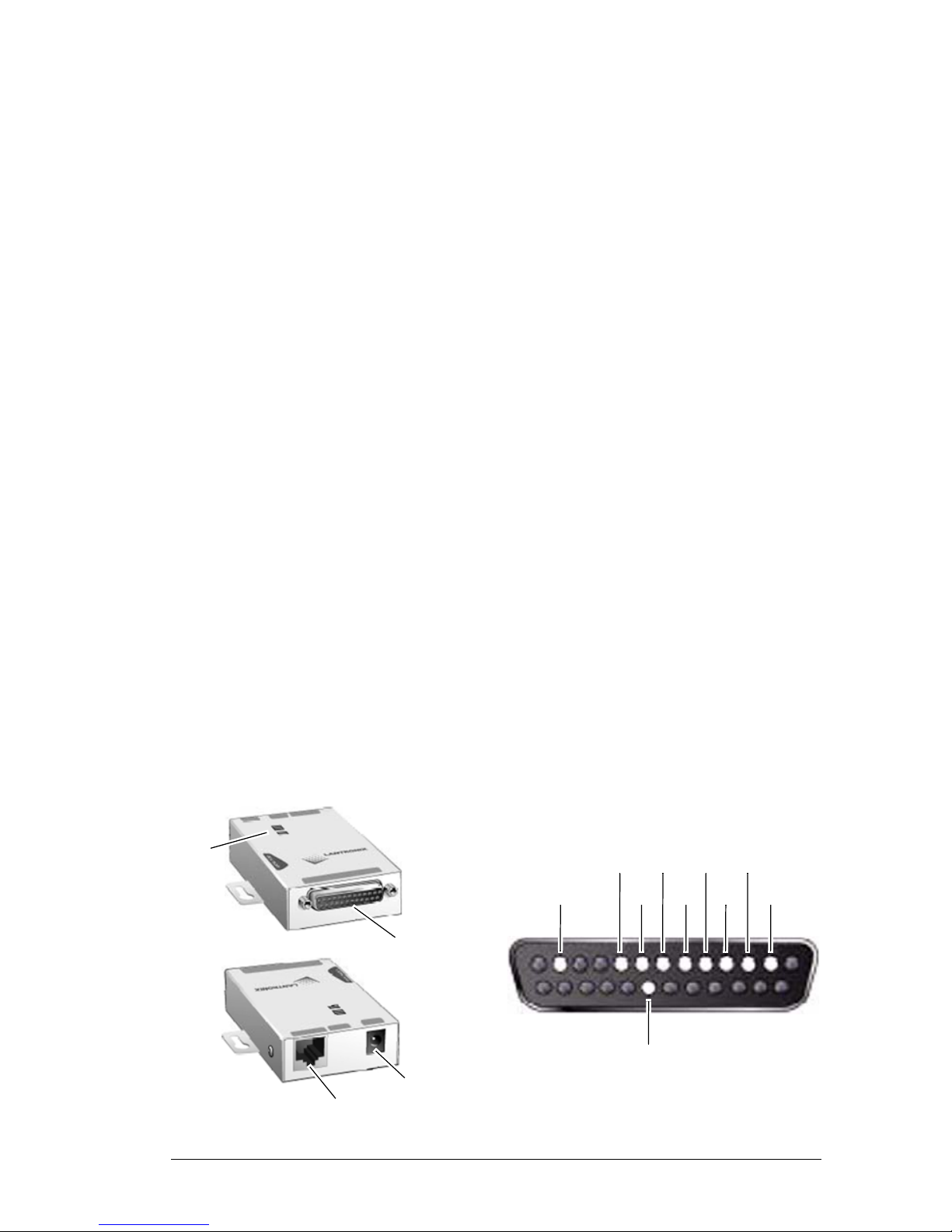
Pinouts and Connections
LEDs
DB25Serial Port
RJ45 Ethernet Port
Power Plug
13
25
14
1
RTS
in
out
DSRDCD
DTR in
TX
GND
CTS RX
*9-30VDC
*+3.3VDC
reg.out
unreg.in out out in
out
DB25 Female DCE Interface RS232
* Optional Power Connection
Page 4

LANSRLU1 Honeywell Access Systems
4 7-101002-00
LEDs
The UDS100 device uses LEDs to
indicate the following conditions:
• 10 Mbps Link/Activity (green)
• 100 Mbps Link/Activity (green)
• Collisions
• Diagnostics (red)
• Status (yellow)
Assigning the IP Address
LEDs Definition
10 Mbps Link/Activity steady (green). Valid 10 Mbps network connection.
10 Mbps Link/Activity blinking (green). Network packets transmitting and receiving.
100 Mbps Link/Activity steady (green). Valiid 100 Mbps network connection.
100 Mbps Link/Activity blinking (green). Network packets transmitting and receiving.
Collisions blinking red. Network collisions.
Diagnostics steady red and status
blinking green.
1 blink = EPROM checksum error.
2 blinks = RAM error.
4 blinks = EEPROM checksum error.
5 blinks = Duplicate IP address on networ.k
Diagnostics blinking red and status
blinking green.
4 blinks = Faulty network connection.
5 blinks = No DHCP response.
Status steady green. Serial port not connected to network.
Status blinking green. Serial port connected to network.
Method Description
DeviceInstaller User manually assigns the IP address using a GUI.
The UDS unit must be attached to the network.
ARP and Telnet User manually assigns the IP address and other net-
work settings at a command prompt using UNIX ro a
Windows based system. The user must be logged
onto the configuration port (9999).
Serial Port Login Configure the unit through a serial connection.
Note: The UDS device is shipped with a default IP address of 0.0.0.0.
Page 5
7-101002-00 5
Honeywell Access Systems LANSRLU1
Programming
DeviceInstaller
The user can manually assign the IP address using the DeviceInstaller, which is
on the product Lantronix CD.
Install the DeviceInstaller
1. Insert the product CD into your CD-ROM drive. The Lantronix UDS100
Device Server window displays.
If the CD does not launch automatically:
a. Click the Start button on the Task Bar and select Run.
b. Enter your CD drive letter, colon, backslash, and deviceinstaller .exe
(e.g., E:\deviceinstaller.exe).
2. Click the DeviceInstaller button. The installation wizard window displays.
3. Respond to the installation wizard prompts. (When prompted to select an
installation type, select Typical.)
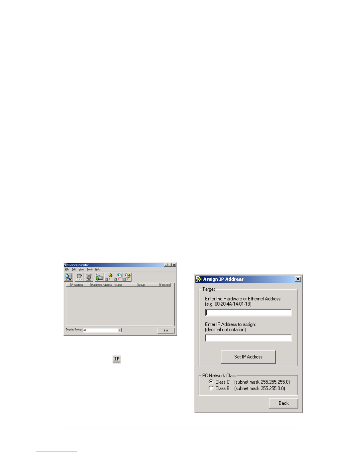
Assign IP Address and Network Class
1. Click the Start button on the task
bar and select Programs Device–
Installer DeviceInstaller. The
DeviceInstaller window appears.
2. Observe the menu bar and tool
bar . Select on the tool bar in
order to assign a New IP Address.
A dialogue box will appear
prompting that an Ethernet
(MAC) Address and the desired
IP Address be entered.
3. Enter in the MAC Address and
the IP Address of the UDS100
device.
Note that the appropriate Subnet
Mask is required at this point.
Page 6

LANSRLU1 Honeywell Access Systems
6 7-101002-00
4. Once the MAC Address, IP
Address and Subnet Mask have
been entered, select the Set IP
Address button.
DeviceInstaller will then perform the following steps before
the message 'Assign IP successful!' appears:
• Test for an existing IP…
• Ping the new IP…
5. Then select OK.
6. On the Assign IP Address screen,
select Back.
7. The main DeviceInstaller win-
dow will reappear. On the tool
bar, select .
8. Select 'Start Search' as well as the
'PC Network Class'.
9. After receiving a response from
the unit(s), displaying the
assigned IP, select 'Save'.
10. Select 'OK' on the window con-
firming the successful update of
the unit(s).
11. On the Search Network window,
select 'Back'.
The user will then be back at the
Main DeviceInstaller window.
12. If adding more than one device,
select the one that is to be configured first.
13. On the Menu Bar, select Tool
then Device Manager…
A Device Management window
will appear displaying four management options.
Page 7

7-101002-00 7
Honeywell Access Systems LANSRLU1
14. For the purposes of programming
the UDS100, select option four,
'Telnet to Device'.
Connecting through port 9999,
the user will be connected to a
Telnet session.
15. A Lantronix Device Universal
Server DOS screen will appear
prompting the user to press Enter
to go into Setup Mode. Press
<enter>.
The duration of programming
will be completed through the
DOS screen.
16. At the 'Your Choice?' prompt,
Enter "0" then <enter> to go into
Server Configuration.
17. At the IP Address prompt, Enter
the IP Address of the UDS100
then <enter>.
18. At the Gateway IP Address
prompt
a. Hit enter immediately if no
gateway is required.
b. Type 'Y', if a gateway is
used. If the user selects 'Y',
at the Gateway IP Addr
(000) prompt, enter the gateway address then <enter>.
19. At the Netmask Number of Bits
for Host Part (0=default) (00)
prompt, enter 8,16 or 24 pending
the subnet mask class being used:
8 = Class C = subnet
255.255.255.0
16 = Class B = subnet
255.255.0.0
24 = Class A = subnet 255.0.0.0
20. Change Telnet Config Password
(N), press <enter>.
The Change Setup Menu will
now re-appear.
21. At the 'Your Choice ?' prompt,
enter "1" thenn <enter> in order
to go into the Channel 1 Configuration.
22. At the Baud Rate prompt, enter
9600 then <enter>.
23. I/F Mode is not used, press
<enter>.
24. At the Flow prompt, type 00 then
<enter> in order to disable Flow
Control.
25. At Port No (10001), type, 3001
then <enter>.
Page 8

LANSRLU1 Honeywell Access Systems
8 7-101002-00
26. At the ConnectMode (C0)
prompt, enter C1 for remote configuration then <enter>.
27. At the Remote IP Address
prompt, if configuring the
Remote UDS100 at this time,
press the enter key four times so
no Remote IP is assigned.
28. At the Remote (0): prompt, enter
3001then <enter>.
29. Press <enter> through the rest of
the menu options.
The Change Setup Menu will
now re-appear.
30. Type 9, <enter> to Save and Exit.
After Exiting the TELNET configuration screen the user will
then return to the DeviceInstaller
software.
The user will then notice a screen
specifying a Target Source.
31. To test com municat ions, under
the Ports option, enter in 3001
and then select OK.
If able to communicate through
the UDS100 on port 3001, the
user will notice a black screen
with a blinking cursor.
32. Upon completion, exit out of
DeviceInstaller.
Programming the UDS100 with Windows Command Prompts
1. Connect the UDS100 to the net-
work.
2. On the Windows Menu Bar,
select Start > Run.
3. Enter in CMD then <enter>.
4. At the Command Prompt, enter in
the following then press <enter>:
ARP -s_IP Address_MAC
Address,
i.e. ARP -s 192.168.1.14 00-20-
4A-64-CC-3D.
5. In order to confirm the assign-
ment of the IP Address and
MAC, at the next command
prompt enter in ARP -A, <enter>.
6. At the following Command
Prompt, enter in TELNET then
<enter>.
7. Enter in OPEN_IP Address_1
then <enter>,
i.e. OPEN 192.168.1.14 1.
Page 9

7-101002-00 9
Honeywell Access Systems LANSRLU1
The user will notice an error message that reads as follows:
Could not open a connection to
host on Port 1: connection failed
8. At the following Command
Prompt, enter OPEN_IP
Address_9999 then <enter>,
i.e. OPEN 192.168.1.14 9999
9. A Lantronix Device Universal
Server DOS screen will appear
prompting the user to Press Enter
to go into Setup Mode. Press
<enter>.
10. At this point, complete steps #21
through #30 of the IP address
procedure that begins on page 5.
11. Exit the TELNET session.
Serial Programming through HyperTerminal
1. On the Windows Menu Bar , go to
Start > Programs > Accessories >
Communications > HyperTerminal.
2. A Connection Description screen
will appear, prompting the User
to 'enter a name and choose an
icon'. Enter a name and select
OK.
3. A Connect to screen will appear.
Under the category 'Connect
using'. Select the COM Port in
use with the UDS100.
4. At last a COM Properties screen
will appear. Make the following
changes:
Bits per second = 9600.
Data Bits = 8.
Parity = None.
Stop Bits = 1.
Flow Control = None.
5. Select OK.
The user will then notice a blank
screen with a blinking cursor.
6. To ent er Setup Mode, whi le hold-
ing down the 'x' key, cycle power
to the UDS100 (power off and
back on).
7. When the device reports back
information, immediately press
<enter>.
8. At this point, complete steps #21
through #30 of the IP address
procedure that beginns on page 5.
9. Upon completion,exit the Hyper-
Terminal session.
Page 10

LANSRLU1 Honeywell Access Systems
10 7-101002-00
WIN-PAK 2.0/Pro/Intl. R3 Configuration with UDS100
1. Be sure all devices are properly
configured and attached over the
network.
2. Log into the WIN-PAK 2/Pro
User Interface.
3. On the WIN-PAK Menu Bar, go
to Configuration > Device >
Device Map.
4. Assuming the 485 Loop has
already been configured, rightclick on the 485 and select Configure.
5. Notice two tabs, Basic Informa-
tion and Port Settings. Select the
Port Settings tab.
6. Under Port, press the drop down
arrow and select TCP/IP connection.
7. At this point, enter an IP Address
or Node name.
8. After the IP Address has been
entered, exit the Loop Configuration by selecting OK.
9. At this point, continue with the
system programming.
10. Upon completion of program-
ming, test communication by Initializing the panel(s).
Page 11

7-101002-00 11
Honeywell Access Systems LANSRLU1
System Design
Connection Alternatives
Null Modem Gender Changer 25-pin M-M
UDS100 Device
N485PCI2L
HUB
NCI Card
RS-232
PANE LS
ETHERNET
CABLE
Connection Description Remedy
N-485-HUB-2 • 25-pin male on serial end.
• HUB firmware is used for
dial-up systems.
Replace the HUB firmware chip with
a PCI firmware chip. Be sure that the
version PCI matches that of the HUB.
N-485-PCI-2 • 9-pin female on serial end.
• Designed for direct connect.
Use a 9-pin to 25-pin M-M Null
modem adapter to interface between
the PCI and the UDS100.
N485PCI2L • 25-pin female on serial end.
• Designed for connection to
the LANSRL or LANSRLT.
Use a 25-pin M-M Null modem
adapter between the PCI and the
UDS100.
Page 12

LANSRLU1 Honeywell Access Systems
12 7-101002-00
Problems and Error Messages
Problem/Message Reason Solution
When issuing the ARP -S
command in Windows,
"The ARP entry addition
failed: 5" message displays.
The user currently logged
in does not have the correct rights to use this command on this PC.
Have someone from the IT
department log in a userwith sufficient rights.
When attempting to assign
an IP address to the UDS
via the ARP method, the
"Press Enter to go into
Setup Mode" error
(described below) displayed. Now when Telneting to the UDS, the
connection fails.
When Telneting into port 1
on the UDS, a temporary
IP address is being
assigned. When Telneting
into port 9999 without
pressing <enter> quickly,
the UDS will reboot, causing it to lose the IP
address.
Telnet back into Port 1.
Wait for it to fail, then Telnet to port 9999 again.
Make sure to press
<enter> quickly. (Only be
allocated 5 seconds to
press <enter>.)
When Telneting to port
9999, the message "Press
Enter to go into Setup
Mode" displays. However,
nothing happens when
pressing <enter>, or the
connection is closed.
The <enter> was not
pressed quickly enough.
Only have 5 seconds are
allocated to press<enter>
before the connection is
closed.
Telnet to port 9999 again,
but press <enter> as
soon as the message
"Press Enter to go into
Setup Mode” appears.
When Telneting to port 1 to
assign an IP address to
the UDS, the Telnet window does not respond for
a long time.
The Ethernet address may
have been entered incorrectly with the ARP command.
Verify that the Ethernet
address that was entered
with the ARP command is
correct. The Ethernet
address may only include
numbers 0-9 and letters AF. In Windows and usually
in Unix, the segments of
the Ethernet address are
separated by dashes. In
some forms of Unix, the
Ethernet address is segmented with colons.
The IP address being
assigned is not on the logical subnet.
Confirm that the PC has an
IP address and that it is in
the same logical subnet as
the UDS.
The UDS may not be
plugged into the network
properly.
Make sure that the Link
LED is illuminated. If the
Link LED is not illuminated,
then the UDS is not properly plugged into the network.
Page 13

7-101002-00 13
Honeywell Access Systems LANSRLU1
When attempting to assign
an IP with DeviceInstaller,
the following message
appears: "No response
from device! Verify the IP,
Hardware address and
Network Class. Please try
again."
The cause is most likely
one of the following: The
Hardware address specified is incorrect. The IP
address being assigned is
not a valid IP for the logical
subnet.
The correct subnet mask
was not selected.
Double-check the specified parameters. Tip: An IP
address cannot be
assigned to a UDS
through a router.
No LEDs are illuminated. The unit or its power sup-
ply is damaged, or the unit
is not plugged into power
properly.
Try plugging the UDS into
another outlet. If this does
not fix the problem, contact the dealer or Lantronix
Technical Support for a
replacement.
The UDS100 will not power
up properly, and the LEDs
are flashing.
Various. Consult the LEDs section
in the Introduction chapter
or the Quick Start guide for
the LED flashing sequence
patterns. Call Lantronix
Technical Support if the
blinking pattern indicates a
critical error.
The UDS is not communicating with the serial
device attached to the
UDS.
The most likely reason is
the wrong serial cable or
serial settings were chosen.
Make sure to use the correct serial cable. The UDS
serial port is just like a
modem serial port (DCE).
The serial settings for the
serial device and the UDS
must match. The default
serial settings for the UDS
are RS232, 9600 Baud, 8
Character Bits, No Parity, 1
Stop Bit, No Flow Control.
When attempting to enter
the setup mode on the
UDS via the serial cable,
there is no response.
The issue will most likely
be something covered in
the previous problem, or
possibly the Caps Lock is
on.
Double check everything
in the problem addressed
above. Confirm that Caps
Lock is not on.
Problem/Message Reason Solution
Page 14

LANSRLU1 Honeywell Access Systems
14 7-101002-00
It’s possible to ping the
UDS, but not Telnet to the
UDS on port 9999.
There may be an IP
address conflict on the
network Port 9999 is not
being Telnetted.
The Telnet configuration
port (9999) is disabled
within the UDS security
settings.
Turn the UDS off and then
issue the following commands at the DOS prompt
of the computer: ARP -D
X.X.X.X (X.X.X.X is the IP
of the UDS).
PING X.X.X.X (X.X.X.X is
the IP of the UDS).
If a response is given, then
there is a duplicate IP
address on the network
(the LEDs on the UDS
should flash a sequence
that tells you this). If no
response is given, use the
serial port to verify that Telnet is not disabled.
With DeviceInstaller a
"Wrong Password" error is
given when attempting to
upgrade the firmware.
An incorrect setting was
chosen for the Existing
Firmware filed.
Try upgrading the firmware
again, but make sure to
use the correct setting in
the field of Existing Firmware field.
Problem/Message Reason Solution
Page 15

7-101002-00 15
Honeywell Access Systems LANSRLU1
The correct serial cable is
used, and the UDS is
setup correctly, but there is
no communication with the
device attached to the
UDS across the network.
If the serial cable is correct, perhaps it is not connected to the correct
socket of the UDS.
Another possibility is that
the UDS is not set up correctly to make a good
socket connection to the
network.
Check to see whether
there is a socket connection to or from the UDS by
looking at the Status LED.
If the Status LED is blinking consistently, or is completely off, then there is a
good socket connection.
If the Status LED is solid
green, then the socket
connection does not exist.
Use the Connect Mode
option C0 for making a
connection to the UDS
from the network. Use
Connect Mode option C1
or C5 for a connection to
the network from the UDS.
When connecting to the
Web-Manager within the
UDS, the message "No
Connection With The
CoBox" displays.
The computer is not able
to connect to port 30718
(77FEh) on the UDS.
Make sure that port 30718
(77FEh) is not blocked
with any another router
being used on the network. Also make sure that
port 77FEh is not disabled
within the Security settings
of the UDS.
Problem/Message Reason Solution
Page 16

Honeywell Access Systems LANSRLU1
Honeywell Access Systems
135 West Forest Hill Avenue
Oak Creek, WI 53154
PH: 414-766-1700
FX: 414-766-1798
www.honeywellaccess.com Specifications subject to change without notice.
© 2004 Honeywell International. All rights reserved. 7-101002-00
Adapter Pinouts for 9-pin and 25-pin Connectors
Null Modem Adapter: 9-to-25 pin Straight-through Adapter: 9-to-25 pin
9DB to 25DB 9DB to 25DB
2-RX 2TX 2-TX 3-TX
3-TX 3-RX 3-RX 2-RX
5-SG 7-SG 5-SG 7-SG
Null Modem Adapter: 9-to-9 pin Straight-through Adapter: 9-to-9 pin
9DB to 9DB 9DB to 9DB
2-RX 3-TX 2-TX 2-TX
3-TX 2-RX 3-RX 3-RX
5-SG 5-SG 5-SG 5-SG
Null Modem Adapter: 25-to-25 pin Straight-through Adapter: 25-to-25 pin
25DB to 25DB 25DB to 25DB
2-TX 3-RX 2-TX 2-TX
3-RX 2-TX 3-RX 3-RX
7-SG 7-SG 7-SG 7-SG
Note: RX = Receive; TX = Transmit; SG = Ground.
 Loading...