

Page 1

RELEASED FOR THE EXCLUSIVE USE BY: AIRCRAFT ELECTRONICS ASSOCIATION
h
INSTALLATION MANUAL
KI 208, KI 209
NAVIGATION INDICATORS
MANUAL NUMBER 006-00140-0004
Revision 4, August 2002
UP536434
Page 2

RELEASED FOR THE EXCLUSIVE USE BY: AIRCRAFT ELECTRONICS ASSOCIATION
WARNING
PRIOR TO EXPORT OF THIS DOCUMENT, REVIEW FOR EXPORT LICENSE
REQUIREMENT IS NEEDED.
COPYRIGHT NOTICE
©1988, 1996, 2002 HONEYWELL INTERNATIONAL INC.
UP536434
REPRODUCTION OF THIS PUBLICATION OR ANY PORTION THEREOF BY ANY
MEANS WITHOUT THE EXPRESS WRITTEN PERMISSION OF HONEYWELL IS
PROHIBITED. FOR FURTHER INFORMATION CONTACT THE MANAGER, TECHNICAL
PUBLICATIONS, HONEYWELL, ONE TECHNOLOGY CENTER, 23500 WEST 105TH
STREET OLATHE KS 66061 TELEPHONE: (913) 782-0400.
Page 3

RELEASED FOR THE EXCLUSIVE USE BY: AIRCRAFT ELECTRONICS ASSOCIATION
BENDIX/KING KI 208, KI 209
REVISION HISTORY
INSTALLATION MANUAL
BENDIX/KING
KI 208, KI 209
Navigation Indicators
PART NUMBER REV DATE DESCRIPTION
--------------------------------------------------------------------------------------------------------------------006-00140-0004 4 Aug/2002 Replaces P/N 006-00140-0003.
006-00140-0003 3 Oct/1996 Replaces P/N 006-00140-0002.
006-00140-0002 2 Mar/1988 Replaces P/N 006-00140-0001.
UP536434
Rev 4, Aug 2002 IM 006-00140-0004 RH-1
Page 4

RELEASED FOR THE EXCLUSIVE USE BY: AIRCRAFT ELECTRONICS ASSOCIATION
BENDIX/KING KI 208, KI 209
THIS PAGE RESERVED
UP536434
Rev 4, Aug 2002 IM 006-00140-0004 RH-2
Page 5

RELEASED FOR THE EXCLUSIVE USE BY: AIRCRAFT ELECTRONICS ASSOCIATION
BENDIX/KING TABLE OF CONTENTS KI 208, KI 209
SECTION I
GENERAL INFORMATION
Paragraph Page
1.1 Introduction .............................................................................................1-1
1.2 Equipment Description.............................................................................1-1
1.3 Technical Characteristics.........................................................................1-1
1.4 Units and Accessories Supplied ..............................................................1-2
1.5 Accessories Required, But Not Supplied.................................................1-3
1.6 License Requirements.............................................................................1-3
1.7 Requirements for TSO’d VOR/ ILS/ Glideslope System..........................1-3
LIST OF TABLES
Table Page
1-1 Technical Characteristics KI 208, KI 209.................................................1-1
SECTION II
INSTALLATION
Paragraph Page
2.1 General....................................................................................................2-1
2.2 Unpacking and Inspecting Equipment .....................................................2-1
2.3 Installation KI 208, KI 209 .......................................................................2-1
2.4 Post Installation Checkout .......................................................................2-2
LIST OF TABLES
Table Page
2-1 ILS Deflection ..........................................................................................2-3
2-2 Glideslope Deflection...............................................................................2-3
LIST OF ILLUSTRATIONS
Figure Page
2-1 KI 208 Pinout List.....................................................................................2-5
2-2 KI 209 Pinout List.....................................................................................2-6
2-3 Crimping Tool ..........................................................................................2-7
2-4 KI 208, KI 209 Connector Assembly .......................................................2-8
2-5 KI 208, KI 209 Outline and Mounting .....(Dwg 155-05235-0000)...........2-9
2-6 KI 208, KI 209 Typical Interconnect ....... ..............................................2-11
2-7 KI 208 Non-TSO’d System Interconnect.(Dwg 155-01223-0000).........2-13
2-8 KI 209 System Interconnect....................(Dwg 155-01241-0000).........2-15
UP536434
Rev 4, Aug 2002 IM 006-00140-0004 TOC-1
Page 6

RELEASED FOR THE EXCLUSIVE USE BY: AIRCRAFT ELECTRONICS ASSOCIATION
BENDIX/KING TABLE OF CONTENTS KI 208, KI 209
SECTION III
OPERATION
Paragraph Page
3.1 Equipment Operation ..............................................................................3-1
3.2 Indicator Control Functions KI 208, KI 209..............................................3-2
LIST OF ILLUSTRATIONS
Figure Page
3-1 KI 208 Control Functions .........................................................................3-3
3-2 KI 209 Control Functions .........................................................................3-4
UP536434
Rev 4, Aug 2002 IM 006-00140-0004 TOC-2
Page 7

RELEASED FOR THE EXCLUSIVE USE BY: AIRCRAFT ELECTRONICS ASSOCIATION
BENDIX/KING KI 208, KI 209
SECTION I
GENERAL INFORMATION
1.1 INTRODUCTION
This manual contains information relative to the physical, mechanical and electrical
characteristics of the Bendix/King Silver Crown KI 208 and KI 209.
1.2 EQUIPMENT DESCRIPTION
The Bendix/King KI 208 VOR Indicator is designed to operate with VHF navigational
equipment (such as the KX 155, KX 155A, KX 165A) to provide OMNI (VOR) or LOCALIZER (LOC) information. The VHF navigational receiver receives and detects the
omni or localizer information. The KI 208 converts this information to DC signals which
drive the LEFT-RIGHT needle and the TO-OFF-FROM flag of the visual indicator.
The KI 209 ILS Indicator performs the same functions as the KI 208. In addition, it
contains an UP-DOWN glideslope needle with an OFF warning flag.
An anti reflective lens coating is also available on some models of the KI 208 and
KI 209.
1.3 TECHNICAL CHARACTERISTICS
TABLE 1-1 Technical Characteristics KI 208, KI 209
SPECIFICATION CHARACTERISTIC
KI208, KI209 TSO COMPLIANCE: C40a, C36c Class C Cat 2.
DO-138 Environmental Cat. DAPAAAXXXXXX.
ADDITIONAL TSO COMPLIANCE
FOR KI 209 ONLY:
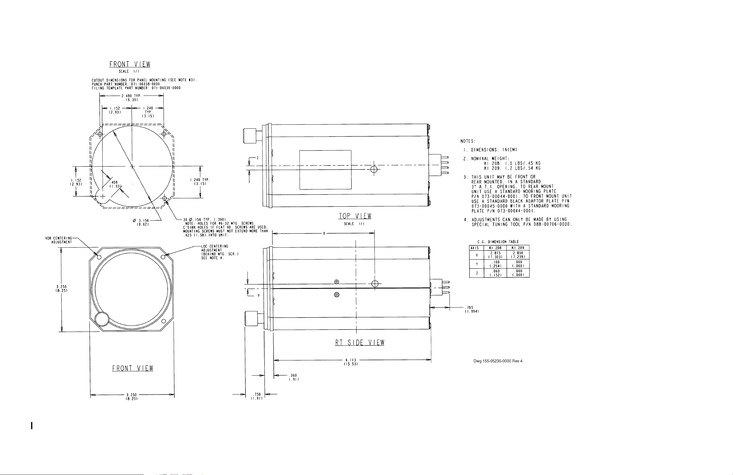
SIZE: See Figure 2-5 (P/N 155-05235-0000).
WEIGHT: See Figure 2-5 (P/N 155-05235-0000).
POWER REQUIREMENTS:
KI 208, KI 209 Indicator
C34c Class D Cat 2.
14 Vdc at 50 mA, 28 Vdc at 50 mA.
UP536434
KI 208 Lighting
KI 209 Lighting
KI 208, KI 209 Lighting
Rev 4, Aug 2002 IM 006-00140-0004 Page 1-1
14 Vdc at 80 ±20 mA.
14 Vdc at 160 ±45 mA.
28 Vdc at 80 ±20 mA.
Page 8

RELEASED FOR THE EXCLUSIVE USE BY: AIRCRAFT ELECTRONICS ASSOCIATION
BENDIX/KING KI 208, KI 209
TABLE 1-1 Technical Characteristics KI 208, KI 209
SPECIFICATION CHARACTERISTIC
VOR/LOC:
Input Impedance:
Nominal Composite Input Level:
Localizer Sensitivity:
OMNI Accuracy:
OMNI Sensitivity:
External Load:
GLIDESLOPE DEVIATION
METER:
Input Impedance:
Deflection Sensitivity:
GLIDESLOPE FLAG:
Input Impedance:
50 k ohms, nominal.
LOC: 0.33 ±10% Vrms.
VOR: 0.50 ±10% Vrms ARINC phased.
4 dB tone ratio will give 3 dot scale deflection.
±2° max error, ±1° typical.
±10° off course gives full scale deflection.
ARINC autopilot deviation (two 1 k loads).
1 k ±5% ohms.
150 ±5% uA for full scale deflection.
1 k ±5% ohms minimum.
Deflection Sensitivity:
125 uA for flag to leave stop.
260 uA maximum for fully concealed flag.
1.4 UNITS AND ACCESSORIES SUPPLIED
1.4.1 KI 208 VOR Indicator
066-3056-00
066-3056-02 Antireflective lens
1.4.2 KI 209 ILS Indicator
066-3056-01
066-3056-03 Antireflective lens
1.4.3 Bendix/King Equipment Installation Kit (P/N 050-01550-0000) which includes
mating connectors, mounting hardware, etc., is as follows:
UP536434
Rev 4, Aug 2002 IM 006-00140-0004 Page 1-2
Page 9

RELEASED FOR THE EXCLUSIVE USE BY: AIRCRAFT ELECTRONICS ASSOCIATION
BENDIX/KING KI 208, KI 209
PART NUMBER DESCRIPTION QTY VENDOR PART NUMBER
030-02227-0005 Shell, Connector Plug 1 Burndy SMS12P-1
030-02227-0009 Hood, Conn (2 pieces) 1 Burndy SMS12H1
030-02227-0023 Pin, Female Crimp 12 Burndy SC20M-6TK6
088-00706-0000 Tool, Adjustment 1
1.5 ACCESSORIES REQUIRED, BUT NOT SUPPLIED
1.5.1 Antenna.
1.5.2 Interconnecting Cables.
1.5.3 Receiver.
1.5.4 Mooring Plate P/N 073-00044-0001.
1.5.5 Adapter Plate P/N 073-00045-0000 (Front mounting only).
1.5.6 Punch Refer to Figure 2-5 (P/N 155-05235-0000) or other
appropriate drawing.
1.5.7 Filing Template Refer to Figure 2-5 (P/N 155-05235-0000) or other
appropriate drawing.
1.5.8 Crimp Tool Burndy Hytool M8ND
1.5.9 Extraction Tool Handle P/N 005-02012-0012, Burndy RXT20-4P3
1.5.10 Extraction Tool Tip P/N 005-02012-0013, Burndy RXK20-25
1.6 LICENSE REQUIREMENTS
None.
1.7 REQUIREMENTS FOR TSO’D VOR/ILS/GLIDESLOPE SYSTEM
Units used in conjunction with the KI 208, KI 209 must meet the specifications listed
below to comprise a completely TSO’d navigation system.
1.7.1 Navigation Receiver Requirements For Use with KI 208, KI 209.
UP536434
1.7.1.1 The navigation receiver shall be authorized to the standards of TSO C40a,
C40b, C40c, and/or TSO C36c, C36d, C36e.
1.7.1.2 VOR phase error shall not exceed 1.5°.
1.7.1.3 Variation in VOR composite output to not exceed ±3 dB from 0.500 Vrms as
the RF input level of a Standard VOR Test Signal to the receiver is varied from
10 uV to 10,000 uV.
Rev 4, Aug 2002 IM 006-00140-0004 Page 1-3
Page 10

RELEASED FOR THE EXCLUSIVE USE BY: AIRCRAFT ELECTRONICS ASSOCIATION
BENDIX/KING KI 208, KI 209
1.7.1.4 Variation in the LOC composite output shall not exceed ±2 dB from 0.333
Vrms as the RF input level of a Standard Localizer Centering Signal is varied
from 50 uV to 10,000 uV.
1.7.1.5 A control line (ILS Energize) must be provided as a low impedance to ground
when an ILS frequency is selected.
1.7.2 Glideslope Receiver/Converter Requirements For Use with KI 209.
1.7.2.1 The glideslope receiver/converter shall be authorized to the standards of TSO
C34c, C34d, C34e.
1.7.2.2 Centering current to be 0 ±7 uA into a 1000 ohm load with a 95% probability
under all combinations of the service conditions listed in RTCA Paper DO-132,
Minimum Performance Standards - Airborne ILS Glideslope Receiving Equipment paragraph 2.1 sub-paragraph b, Centering Accuracy.
1.7.2.3 Deviation current with a 700 uV Standard Glideslope Deviation Signal (0.091
±0.001 ddm tone ratio) applied to the receiver input shall be 78 ±10% uA into
a 1000 ohm load. Deviation current shall not change more than 15% as the
RF input level of a Standard Glideslope Deviation Signal is varied from 100 to
10,000 uV. Deviation current shall be proportional within 5% to the difference
in depth of modulation of the 90 Hz and 150 Hz tones.
1.7.2.4 Warning signal output shall be a DC current less than 125 uA into a 1000 ohm
load for a warning flag to be fully visible. Warning signal for a fully concealed
warning flag shall be a DC current of 260 uA minimum into a 1000 ohm load.
1.7.3 Fully TSO’D Systems
The following navigation systems will meet all TSO system requirements when
used in conjunction with the KI 208, KI 209:
KX 155
KX 155A
KX 165A
UP536434
Rev 4, Aug 2002 IM 006-00140-0004 Page 1-4
Page 11

RELEASED FOR THE EXCLUSIVE USE BY: AIRCRAFT ELECTRONICS ASSOCIATION
BENDIX/KING KI 208, KI 209
SECTION II
INSTALLATION
2.1 GENERAL
This section contains suggestions and factors to consider before installing the KI 208,
KI 209 Indicator. Close adherence to these suggestions will assure a more satisfactory performance from the equipment.
2.2 UNPACKING AND INSPECTING EQUIPMENT
Exercise extreme care when unpacking each unit. Make a visual inspection of each
unit for evidence of damage incurred during shipment. If a claim for damage is to be
made, save the shipping container to substantiate the claim. When all equipment is
removed, place in the shipping container all packing materials for use in unit storage
or reshipment. The KI 208, KI 209 installation will conform to standards designated by
the customer, installing agency and existing conditions as to unit location and type of
installation.
NOTE
This equipment has plastic lenses. Use extreme
caution when cleaning.
2.3 INSTALLATION KI 208, KI 209
2.3.1 Installation Procedure
2.3.1.1 Carefully select the KI 208, KI 209 panel location for unobstructed vision, min-
imum parallax, and adequate clearance for the instrument case and installation of cables and connectors.
2.3.1.2 Refer to Figure 2-5 (P/N 155-05235-0000), or other appropriate drawing, for
the KI 208 and KI 209 mounting dimensions.
2.3.1.3 A standard 3 1/8 inch instrument hole is required. Refer to Figure 2-5 (P/N
155-05235-0000), or other appropriate drawing, for hole punch or filing templates.
2.3.1.4 Secure the KI 208, KI 209 firmly in place using the mounting screws supplied.
If the mounting screw supplied are not used, #6-32 mounting screws that do
not extend more than 0.625 inches (1.59 cm) into the unit may be used.
UP536434
2.3.1.5 The installing agency will supply and fabricate the external cable. The plugs
required are supplied by Bendix/King.
2.3.1.6 The KI 208, KI 209 will drive two external deflection indicator loads of 1000
ohms or greater impedance.
2.3.1.7 An omni phase adjust potentiometer, R233 is accessible from the front of the
indicator by removing the upper left mounting screw. The 2 1/2 inch long adjustment tool (P/N 088-00706-0000) is required to adjust the omni phase ad-
Rev 4, Aug 2002 IM 006-00140-0004 Page 2-1
Page 12

RELEASED FOR THE EXCLUSIVE USE BY: AIRCRAFT ELECTRONICS ASSOCIATION
BENDIX/KING KI 208, KI 209
just potentiometer. This is for final calibration of the omni system after installing in aircraft. The range of the error potentiometer is approximately ±25°. It
should be noted that this potentiometer does not affect localizer centering.
The localizer centering potentiometer R227 is accessible from the front of the
indicator by removing the upper right mounting screw. Again the 2 1/2 inch
long adjustment tool is required.
2.3.2 CABLING
2.3.2.1 The length and routing of the external cables must be carefully studied and
planned prior to the installation. Avoid sharp bends and placing cables too
near the aircraft control cables.
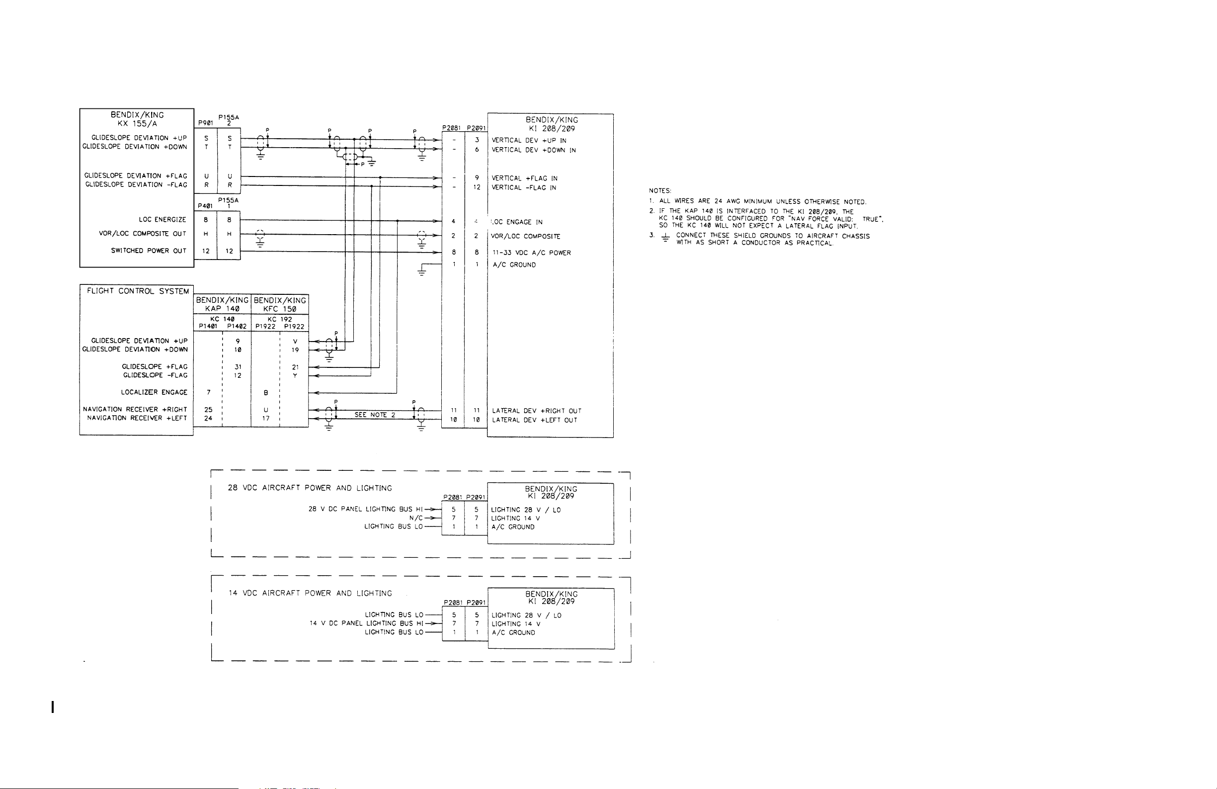
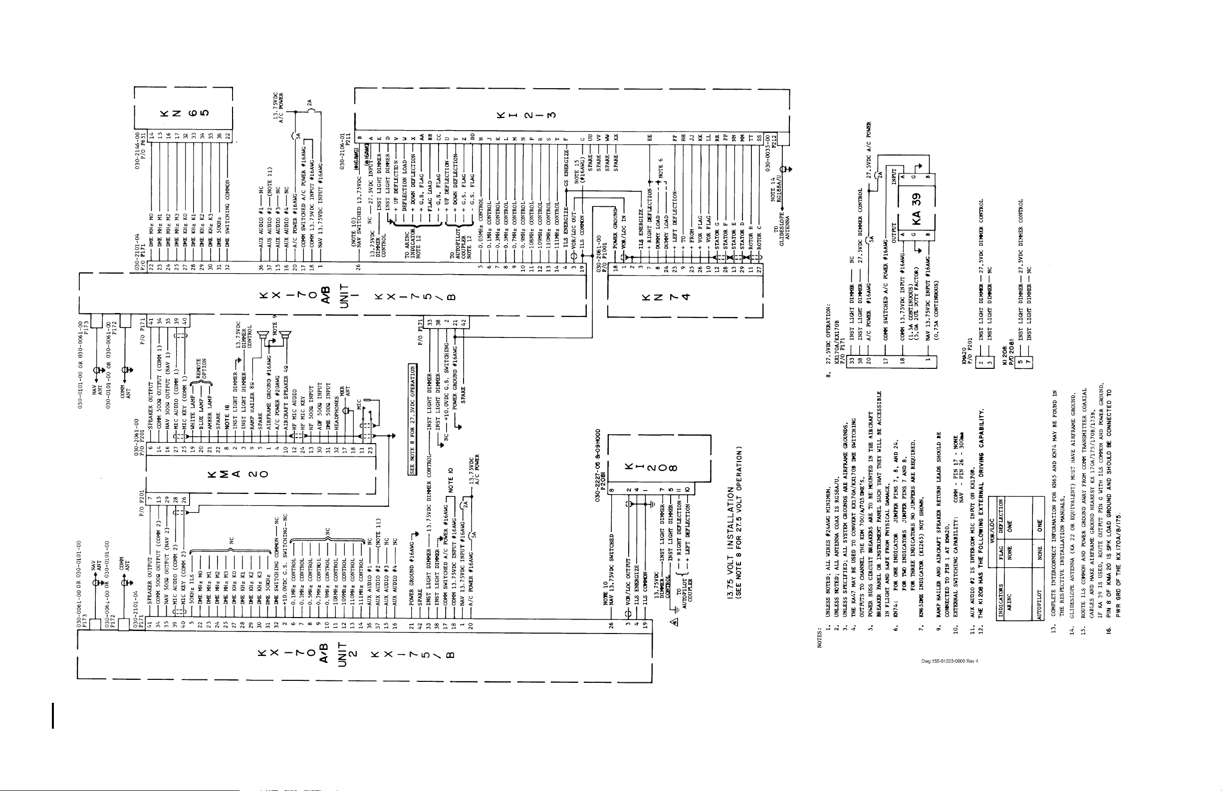
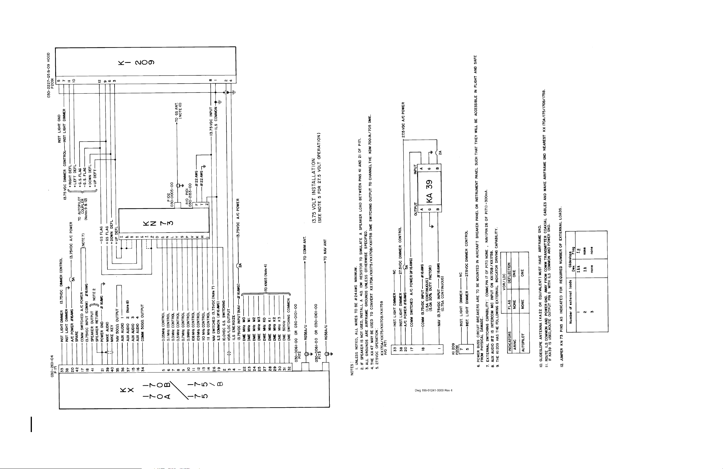
2.3.2.2 Fabricate the external cables in accordance with the installation drawing that
fulfills the system requirement.
2.3.2.3 Avoid running the interconnect harness between the KI 208 and navigation re-
ceiver too close to any transmitter antenna coax cable.
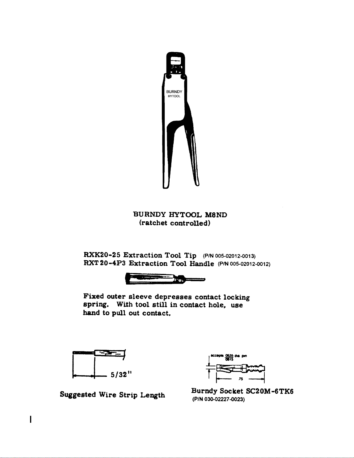
2.3.2.4 Considerable savings of installation time can be realized by using the Burndy
crimping tool shown in Figure 2-3.
2.4 POST INSTALLATION CHECKOUT
An operational ramp test or performance flight test is recommended after installation
to insure satisfactory performance of the equipment in its normal environment.
2.4.1 RAMP TEST
2.4.1.1 Use VOR/ILS ramp generator IFR 401L or equivalent.
2.4.1.2 Set ramp generator to VOR, 90° TO. Set NAV receiver to VOR frequency.
Rotate OBS until the D-bar centers, with the To/From indicator reading TO.
The OBS should read 90° TO ±2°. Change the generator to 0° TO, center the
D-bar, and check the OBS reading for 0° TO ±2°.
2.4.1.3 If the error is greater than ±2°, VOR centering may be readjusted by R233 (be-
hind top left mounting screw) using adjustment tool P/N 088-00706-0000.
2.4.1.4 To adjust VOR centering, change the generator to 90° TO, center the D-bar,
and adjust R233 for 0° TO ±2°. Change the generator to 90° FROM, center
the D-bar, and adjust R233 for half the reading at 90° TO. Repeat adjustments at 90° TO and 90° FROM until both are within ±2°. If large corrections
are required to center the needle the source of error may be exist in another
part of the VOR/LOC navigation system.
UP536434
2.4.1.5 Change the generator to 0° TO, center the D-bar for 0° TO. Set OBS to 8° and
check for 4 ±1/2 dots deflection to the Left. Set OBS to 352° and check for 4
±1/2 dots deflection to the Right.
2.4.1.6 Rotate the OBS 360° and verify that the To/From flag changes state only at
270° ±30° and at 90° ±30° OBS position.
Rev 4, Aug 2002 IM 006-00140-0004 Page 2-2
Page 13

RELEASED FOR THE EXCLUSIVE USE BY: AIRCRAFT ELECTRONICS ASSOCIATION
BENDIX/KING KI 208, KI 209
2.4.1.7 Remove VOR RF signal and verify that NAV warning flag appears.
2.4.1.8 Set ramp generator to ILS mode. Set NAV receiver to ILS frequency. Check
the levels in Table 2-1 for ILS deflection and Table 2-2 for Glideslope deflection within ±1/2 dot.
TABLE 2-1 ILS Deflection
SIGNAL LEVEL
PREDOMINATE
MODULATION
DIRECTION
DEFLECTION
(±1/2 dot)
LOC +4 dB (+.093 ddm) 150 Hz LEFT 3 dots
LOC +0 dB (0 ddm) CENTERED ±1/2 dot
LOC -4 dB (-.093 ddm) 90 Hz RIGHT 3 dots
TABLE 2-2 Glideslope Deflection
SIGNAL LEVEL
PREDOMINATE
MODULATION
DIRECTION
DEFLECTION
(±1/2 dot)
GS +2 dB (>.091 ddm) 150 Hz UP 2 1/2 dots
GS +0 dB (0 ddm) CENTERED ±1/2 dot
GS -2 dB (.091 ddm) 90 Hz DOWN 2 1/2 dots
2.4.1.9 If the error is greater than ±1/2 dot, LOC centering may be readjusted by R227
(behind top right mounting screw) using adjustment tool P/N 088-00706-0000
at 0 dB (0 ddm).
UP536434
2.4.1.10 Remove ILS RF signal and verify that NAV/GS warning flag(s) appear.
2.4.2 FLIGHT TEST
2.4.2.1 To check the VOR/ILS System, select a VOR frequency within a forty nautical
mile range. Listen to the VOR audio and insure that no electrical interference
such as magneto noise is present. Check the tone identifier operation. Fly
inbound or outbound on a selected VOR radial and check for proper LEFTRIGHT and TO-FROM indications. Check VOR accuracy for ±5° of a known
heading.
NOTE
VOR ground station scalloping may occur under
weak signal conditions.
Channel off VOR NAV receiver and verify that the NAV warning flag appears.
Rev 4, Aug 2002 IM 006-00140-0004 Page 2-3
Page 14

RELEASED FOR THE EXCLUSIVE USE BY: AIRCRAFT ELECTRONICS ASSOCIATION
BENDIX/KING KI 208, KI 209
2.4.2.2 Flight test the ILS operation by flying a simulated ILS approach. Check local-
izer LEFT-RIGHT deflection and, if applicable, glideslope deflection. Check
the localizer accuracy in relation to the ILS runway.
Channel off ILS NAV receiver and verify that NAV/GS warning flag(s) appear.
UP536434
Rev 4, Aug 2002 IM 006-00140-0004 Page 2-4
Page 15
RELEASED FOR THE EXCLUSIVE USE BY: AIRCRAFT ELECTRONICS ASSOCIATION
BENDIX/KING KI 208, KI 209
UP536434
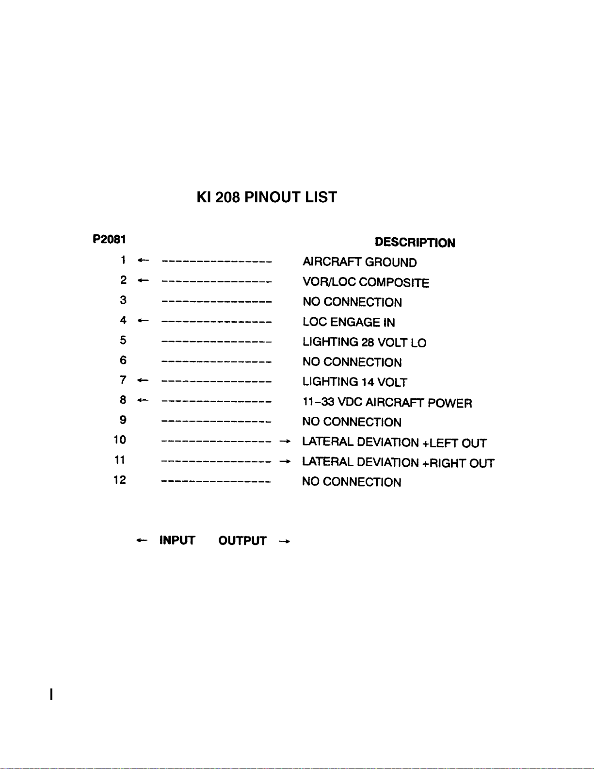
Figure 2-1 KI 208 Pinout List
Rev 4, Aug 2002 IM 006-00140-0004 Page 2-5
Page 16
RELEASED FOR THE EXCLUSIVE USE BY: AIRCRAFT ELECTRONICS ASSOCIATION
BENDIX/KING KI 208, KI 209
UP536434
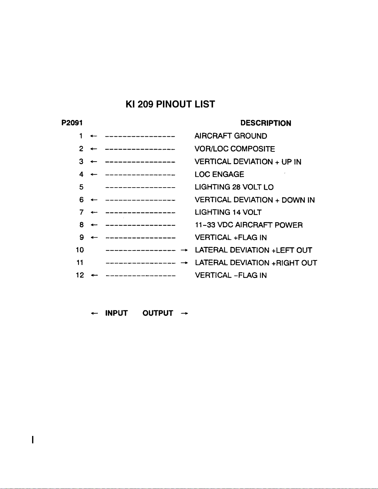
Figure 2-2 KI 209 Pinout List
Rev 4, Aug 2002 IM 006-00140-0004 Page 2-6
Page 17
RELEASED FOR THE EXCLUSIVE USE BY: AIRCRAFT ELECTRONICS ASSOCIATION
BENDIX/KING KI 208, KI 209
UP536434
Figure 2-3 Crimping Tool
Rev 4, Aug 2002 IM 006-00140-0004 Page 2-7
Page 18
RELEASED FOR THE EXCLUSIVE USE BY: AIRCRAFT ELECTRONICS ASSOCIATION
BENDIX/KING KI 208, KI 209
UP536434
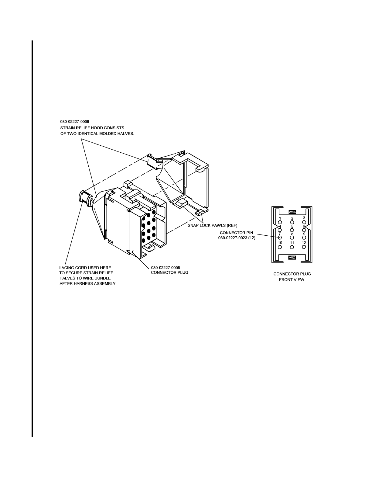
Figure 2-4 KI 208, KI 209 Connector Assembly
Rev 4, Aug 2002 IM 006-00140-0004 Page 2-8
Page 19
BENDIX/KING KI 208, KI 209
UP536434
FIGURE 2-5 KI 208, KI 209 Outline and Mounting Drawing
(Dwg No 155-05235-0000, Rev 4)
Rev 4, Aug 2002 IM 006-00140-0004 Page 2-9
Page 20
BENDIX/KING KI 208, KI 209
UP536434
FIGURE 2-6 KI 208, KI 209 Typical Interconnect
Rev 4, Aug 2002 IM 006-00140-0004 Page 2-11
Page 21
BENDIX/KING KI 208, KI 209
UP536434
FIGURE 2-7 KI 208 Non-TSO’d Silver Crown System Interconnect
(Dwg No 155-01223-0000, Rev 4)
Rev 4, Aug 2002 IM 006-00140-0004 Page 2-13
Page 22
BENDIX/KING KI 208, KI 209
UP536434
FIGURE 2-8 KI 209 System Interconnect
(Dwg No 155-01241-0000, Rev 4)
Rev 4, Aug 2002 IM 006-00140-0004 Page 2-15
Page 23

RELEASED FOR THE EXCLUSIVE USE BY: AIRCRAFT ELECTRONICS ASSOCIATION
BENDIX/KING KI 208, KI 209
SECTION III
OPERATION
3.1 EQUIPMENT OPERATION
All controls required to operate the KI 208, KI 209 are located on the unit’s front panel
and on the front panel of the related NAV/COMM transceivers.
3.1.1 VOR OPERATION (KI 208, KI 209)
Select the desired VOR station frequency with the NAV frequency controls. The NAV
receiver volume control can then be adjusted to positively identify the station or listen
to FSS reports.
To intercept a selected VOR radial (from the station) and fly outbound, turn the OBS
control to set the desired radial under the top indicator index. Maneuver the aircraft to
fly the selected radial magnetic heading plus a 45° intercept angle which will provide
a sufficient intercept angle. The intercept angle should be reduced as the deviation
needle approaches an on-course condition (center) to prevent excessive course
bracketing.
To determine the bearing and fly “To” a selected VOR station, turn the OBS control
until the “To-From” flag resembles a white arrow pointing up and the deviation needle
is centered. Read the “To” bearing under the top indicator index and maneuver the
aircraft to approximately fly the magnetic course “To” the station. If the deviation needle moves to the right, the aircraft course must be adjusted 5 or 10 degrees to the right.
Similarly, if the deviation needle goes to the left, the aircraft course must be adjusted
to the left. Maintaining a centered deviation needle will provide automatic course compensation for wind drift.
3.1.2 LOCALIZER OPERATION (KI 208, KI 209)
Localizer circuits are automatically energized when an ILS frequency is selected on
the KX 155, KX 155A. By adjusting the NAV volume level, the localizer station can be
identified and in some cases, ATIS information received. The localizer flag should disappear from view into the “To” condition indicating the signal is reliable.
Maneuver the aircraft to fly an on-course centered needle. While flying a front course
approach or outbound on the back course approach, magnetic heading corrections
are made toward the needle deflection. Similarly, while flying the back course approach or outbound on the front course approach, corrections are made away from the
needle deflection.
UP536434
The localizer course width is narrow compared to VOR course width and requires
much smaller course corrections to center the deviation needle. When intercepting the
localizer course, the aircraft turn into localizer course should be started when the needle moves off the meter stop.
Rev 4, Aug 2002 IM 006-00140-0004 Page 3-1
Page 24

RELEASED FOR THE EXCLUSIVE USE BY: AIRCRAFT ELECTRONICS ASSOCIATION
BENDIX/KING KI 208, KI 209
A helpful quick reference reminder of the localizer course is to set the course on the
omni-bearing readout.
3.1.3 GLIDESLOPE OPERATION (KI 209)
The glideslope (horizontal) needle provides the pilot with vertical steering information
during ILS approaches. The glideslope circuitry may be energized independently or
when the associated localizer frequency is selected on the navigation receiver. Observe that the glideslope warning flag is concealed. The glideslope needle deflects toward the direction the pilot must fly to remain on the glideslope path. If the glideslope
needle deflects upward, the aircraft is below the glideslope and must climb to center
the needle. If the needle deflects downward, the aircraft is above the glide path and
must descend to remain on the glide path. When the needle is centered the aircraft is
on the glide path.
3.2 INDICATOR CONTROL FUNCTIONS KI 208, KI 209
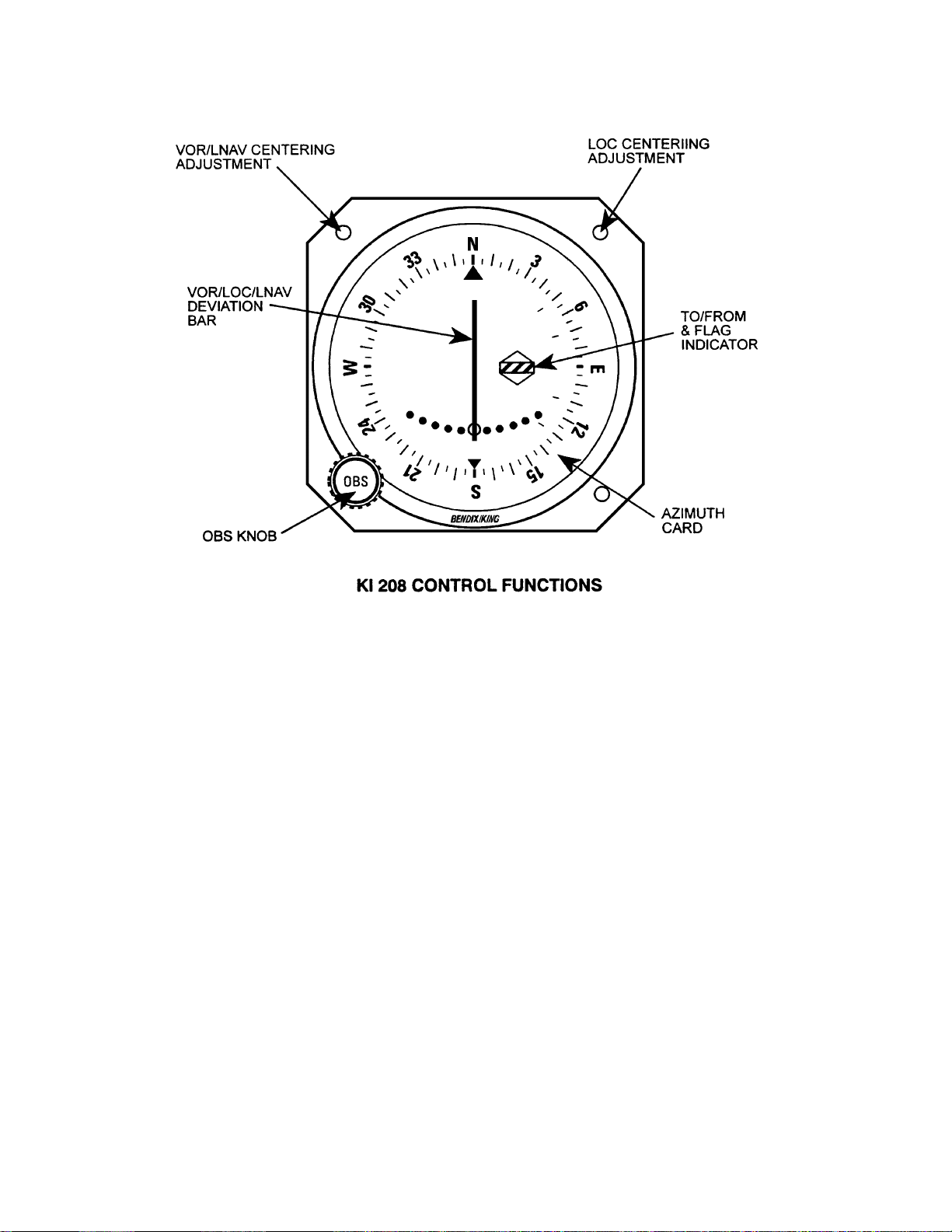
Figure 3-1 displays the control functions of the KI 208. Figure 3-2 displays the control
functions of the KI 209.
3.2.1 OMNI-BEARING SELECTOR (OBS)
The OMNI Bearing Selector knob rotates the azimuth card on which the desired
course is selected. The course selected serves as a reference for all VOR indications.
The reciprocal course is identified under the bottom course index.
3.2.2 VOR/LOC DEVIATION INDICATOR
The VOR/LOC needle deflection indicates the amount of deviation from the selected
VOR course or localizer path. The indicated angular deviation is toward the proper
flight path in normal operation.
The VOR/LOC warning flag is fully visible when the VOR or LOC signal is unreliable.
The VOR TO-FROM flag indicates the direction “TO” or “FROM” the VOR station.
3.2.3 GLIDESLOPE DEVIATION INDICATOR (KI 209 Only)
The glideslope deviation needle deflection indicates the amount of deviation from the
glide path. The deflection is toward the direction of flight required to maintain the proper descent path. The glideslope warning flag is visible when the glideslope signal is
unreliable or the receiver has malfunctioned.
UP536434
Rev 4, Aug 2002 IM 006-00140-0004 Page 3-2
Page 25
RELEASED FOR THE EXCLUSIVE USE BY: AIRCRAFT ELECTRONICS ASSOCIATION
BENDIX/KING KI 208, KI 209
Figure 3-1 KI 208 Control Functions
UP536434
Rev 4, Aug 2002 IM 006-00140-0004 Page 3-3
Page 26

RELEASED FOR THE EXCLUSIVE USE BY: AIRCRAFT ELECTRONICS ASSOCIATION
BENDIX/KING KI 208, KI 209
Figure 3-2 KI 209 Control Functions
UP536434
Rev 4, Aug 2002 IM 006-00140-0004 Page 3-4
 Loading...