

Honeywell IS335 Installation Instructions Manual
1
IS335-010-V0
1
≤
80
lbs / 36
kg
6
'
9"
- 8
'
9"
(2.1 - 2.7 m)
7
'
6"
(2.3 m)
Op
tima
l
2
IS335-014-V0
Pull Up PCB
Push Tabs
IS335-003-V0
IS335 Passive Infrared Motion Sensor – Installation Instructions
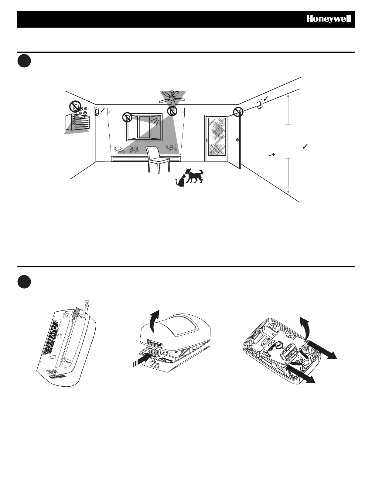
Select the Mounting Location
Mounting location guidelines:
• The optimal range is obtained at a mounting height of 7’ 6” (2.3 m).
• Allow a clear line-of-sight to all areas to protect.
• Do not directly face windows.
• Avoid close proximity to moving machinery, fluorescent lights, and heating/cooling sources.
• For use in applications with pets up to 80 pounds (36 kilograms).
Retrieve Cover Locking Screw, Open Sensor and Remove Circuit Board
Remove tape from back housing
and retrieve cover locking screw.
1. Press firmly on housing latch.
2. Pull up to separate the front
and rear housing.
3
IS335-013-V0
A
B
B
B
A
B
A
B
*
#6 x 1"
(3.5 mm x 25 mm)
IS312QIG-005-V0
4
IS335-006-V0
Shielded
Cable
22-20 AWG
(0.32-0.52mm )
2
5
IS335-012-V0
Push
Down
6
7
#6 x 1"
(3.5mm x 25mm)
CNC V+V-T1T2
1
2
3
Pet Immunity
*Factory default
LED
Always
Enabled
IS335-007-V0
Disabled
*Enabled
Alarm 90 mA, 15 VDC
Power 12 mA max, 9-15 VDC
NC V-V
+
C
Ground +12V
Zone
#
Zone
COM
Panel
Sensor
For Residential use with
compatible panels,
minimally Listed to UL 1023,
that produce visual and/or
audible troubles/alarms
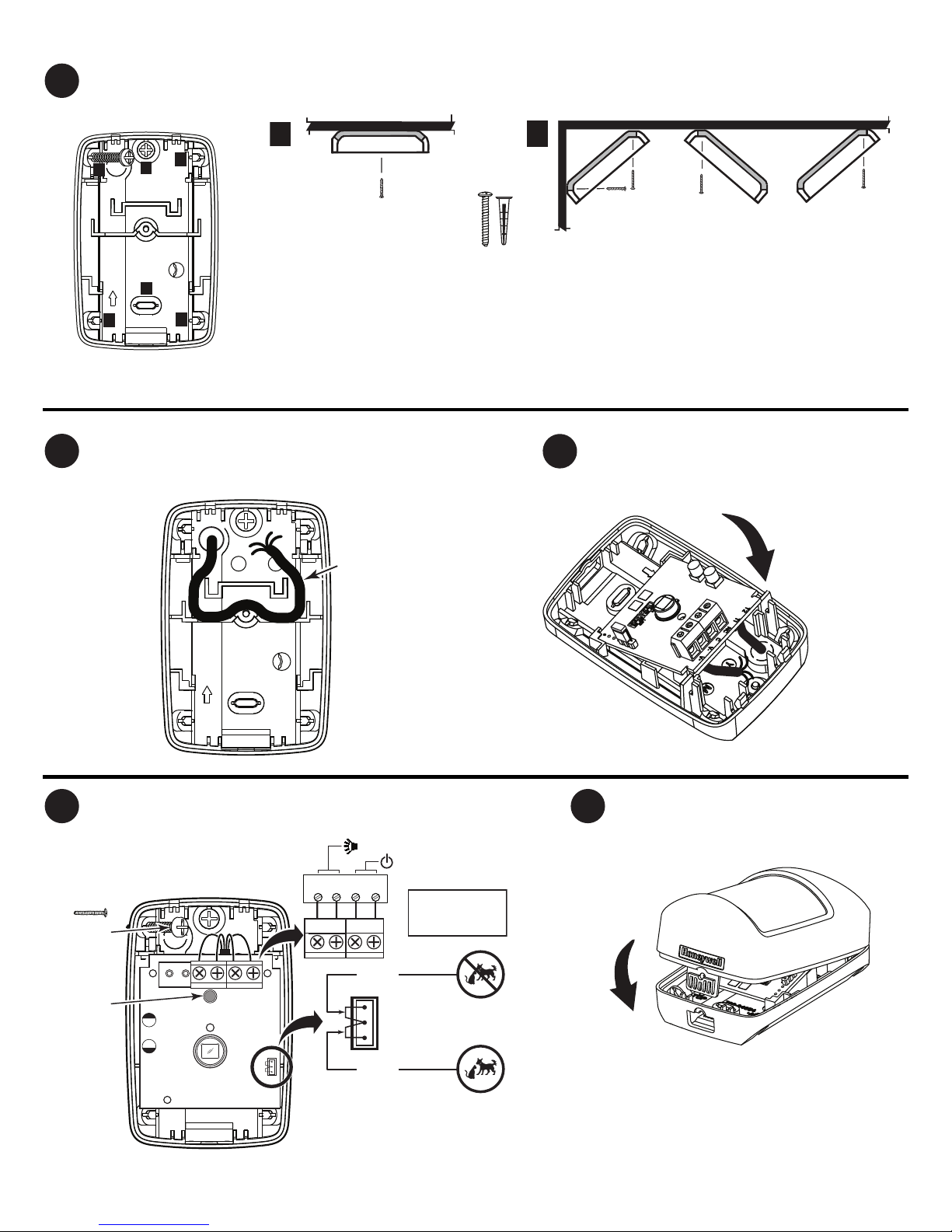
Mount the Sensor
• [A] = Wall mounting holes.
• [B] = Corner mounting holes.
*Not included
R
oute Wires
Reinstall Circuit Board
Connect Wires / Set Pet Immunity (PI) Jumpers
Assemble Front Cover
 Loading...