

Honeywell IS3050A Installation Instructions Manual
1. Turn the arrow to point to the Unlock symbol.
IS3050A Passive Infrared Motion Sensor with Anti-Mask - Installation Instructions
QUICK LINKS
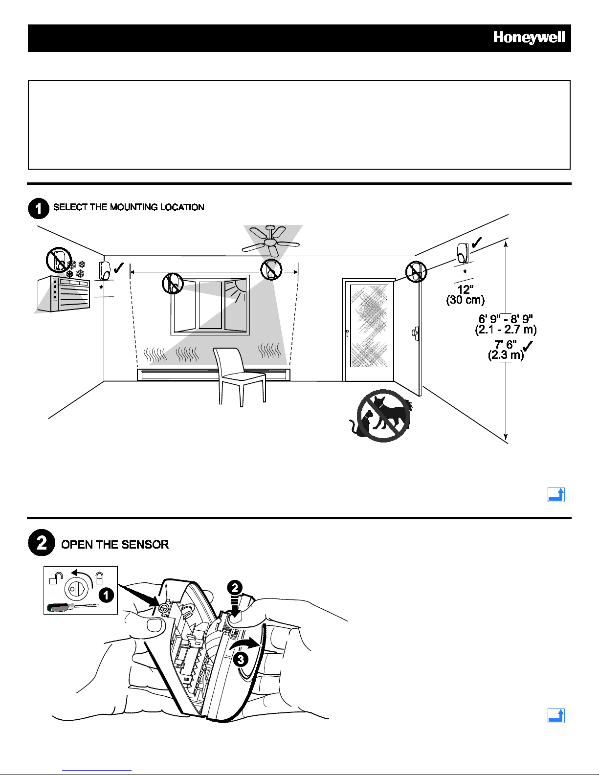
Mounting Location Guidelines
Open the Sensor
Mount the Sensor
Sensor Components and Settings
Wire the Sensor
Wiring Examples
Walk Test the Sensor
Detection Patterns
Remote LED Enable
Relay Operation
Mask Condition
Troubleshooting
Sensor Specifications
Accessories
Approval Listings
Mounting location guidelines:
• The optimal range is obtained at a mounting height
of 7’ 6” (2.3m).
• Allow a clear line-of-sight to all areas to protect.
• Avoid mounting anything within 12” (30cm) in front of the sensor.*
• Do not directly face windows.
• Avoid close proximity to moving machinery, fluorescent lights, and heating/cooling sources.
• Not for use in applications with pets.
2. Press firmly on housing latch.
3. Gently separate the front and rear housing.

• [A] = Wall mounting holes.
See wiring
• [B] = Corner mounting holes.
• The rear tamper plate MUST be
mounted to a stud, solid wood, or
with a robust wall anchor.
details and
examples on
page 3.
- 2 -
 Loading...