

Honeywell IRD 1010, IRD 1020 User Manual
certified Qualitysystem
746e/08/98
ISO 9001 / EN 29001
Reg. Nr. 10529
Infra-red flicker detector
Flame monitoring device for yellow- or blueburning oil flames
INTRODUCTION
The IRD 1010 is employed to monitor the flame of an oil
burner. This flame monitoring device should be connected
to a Satronic oil burner control box. Monitoring is based on
the infra-red flicker principle, in other words, the flickering
infra-red light of the flame is detected. The steady radiation
from, for example, the glowing refractory layer on the inside
of the boiler, has no effect on the detector. The IRD 1010
replaces the models IRD 910, 911 and 911 vi. If exchanging
the units, care must be taken to connect them correctly (see
page 3).
TYPES AVAILABLE (also see page 4, Variants)
Item no. Designation
16501 Flicker detector IRD 1010 right
16502 Flicker detector IRD 1010 end-on
16503 Flicker detector IRD 1010 left
The infra-red flicker detector is suitable for use with the
following control boxes:
IRD 1010 DKO 970, 972, 974, 976
DKW 974, 976
DMO 976
TF 801, 802.1, 804
TF 830.1, 832.1, 834.1, 834E.1, 834.2, 836
TF 844, TF 974, 976
MMD 900, 900.1,
TTO 872, 876
MMO 872, 876
TMO 720-4
A Honeywell Company
TECHNICAL DATA
Supply voltage 220 / 240 V (-15... +10%)
Nominal current input approx. 4 mA
Power consumption 1 VA
Ambient temperature -20° C to +60° C
Insulation standard IP 41
Mounting attitude any
Weight 40 g
Flame viewing attitude side-on or end-on according
Spectral response 800 - 1100 nm
(with daylight filter) maximum 950 nm
Frequency range 15 Hz.... 250 Hz (-12 dB)
Sensitivity adjustment
range approx. 1 : 20 (26 dB)
Switch-on delay < 3.5 sec.
(after connecting
operating voltage)
Response time < 0.1 sec.
Cut-out time < 1 sec.
IRD 1010
50 Hz (50 - 60 Hz)
to type
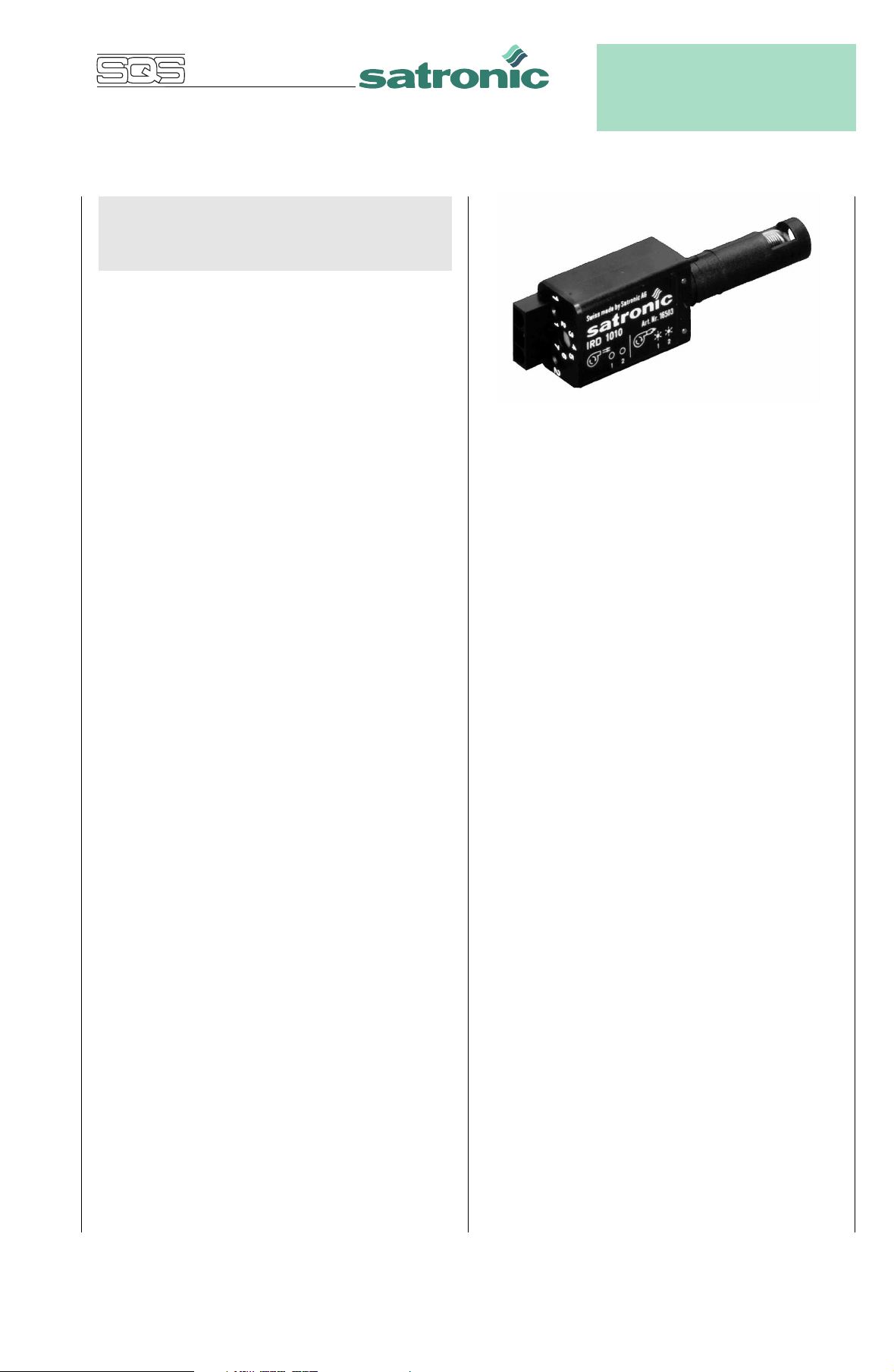
CONSTRUCTIONAL FEATURES
The infra-red sensor and the pre-amplifier are hermetically
sealed in glass and along with the electronics form an
integrated unit in the flame detector. Wiring is by way of a
plug connection. The sensitivity control and two LED’s for
indication of the flame signal are situated on the rear of the
flicker detector.
1

TECHNICAL FEATURES
COMMISSIONING AND MAINTENANCE
1. Flame detection
- Yellow- as well as blue-burning oil flames can be monitored.
- The flame detector is suitable for operation where the
ambient temperature is within the range -20° to +60° C.
- The flickering detector IRD 1010 becomes active not
before a minimum threshold-level of steady light is
exceeded. That guarantees that neither electromagneticnor ignition-spark noise are affecting the IRD.
- Sensitivity is adjustable.
- LED 1 is a warning indicator for the pre-purge phase as
well as normal operation. LED 2 indicates the actual status
of the detector: On or off.
- During pre-purge, LED 1 indicates possible stray light,
which may be produced either by a flickering or by
a steady light source, before the detector switches on
(LED 2).
- When the burner is operating normally, LED 1 acts as a
warning indication of the flame signal current sensitivity
being set too low - it begins to flicker or extinguishes
before the detector switches off.
- The compact dimensions of the detector allow it to be
installed on any burner. The detector shaft has the same
dimensions as the FZ 711 S. It therefore also fits into the
FZ holder M 74.
- Unlike UV tubes, the IRD 1010 flicker detector does not
deteriorate with age.
2. Installation instructions
During commissioning and after servicing, the flame
monitoring system should be checked for faultless operation
as follows:
1. Check that the detector is connected properly. Wrong
connections are a risk to safety, and could cause damage
to the detector unit or burner system.
2. Adjust to maximum sensitivity and start the burner: If the
LED indicator is lit after the start impulse, carefully adjust
the sensitivity control until LED 1 extinguishes. No LED
should light up during the pre-purge phase.
3. With the system set for normal operation, pull out the
detector probe and cover it up to cut off light. Both LED
indicators must extinguish. The control box should switch
to lockout or attempt to re-start the sequence.
4. Attempt to re-start with the flame detector covered.
There must be no indication from the LED’s after the start
impulse. The burner control box must switch to lockout
at the end of the safety interval.
5. Attempt to start the burner with the detector exposed to
stray light e.g. from fluorescent lighting, a cigarette
lighter or light bulb (not daylight or an electric torch):
Depending on the type of control box, it should switch to
lockout either immediately or at the end of the pre-purge,
as a result of stray light.
6. When the burner is operating normally, carefully turn
back the sensitivity control until LED 1 begins to flicker.
Increase the setting again by one or two increments until
both LED’s are lit. If LED 1 does not flicker even at position 1: Leave potentiometer at position 1-2. This adjustment should be carried out when the flame signal current
is weakest (shortly after flame establishment or after
stabilisation).
- The detector probe should be fitted so that it receives the
light which pulsates most strongly. This can be achieved
by positioning the detector as close as possible to the
flame or by directing it at a particular zone of the flame (e.g.
by using a sighting tube).
- No stray light must be allowed to fall on the detector (e.g.
through cracks or from a sight glass). Pulsating stray light
(e.g. from fluorescent lighting or light bulbs) could cause
the system to switch to lockout. Due to the very high
sensitivity of the detector, it should not be exposed
directly or indirectly (reflections) to the ignition spark.
- The infra-red flicker detector should be fitted in such a way
that the ambient temperature cannot under any
circumstances rise above 60 °C. At higher temperatures,
there is a risk of incorrect operation and the life expectancy
of the unit could be reduced. In addition, care should be
taken that the detector is not subjected to unusually harsh
vibration and receives no hard knocks.
The flame detection device requires no maintenance of any
kind, and as it is classed as safety equipment, no attempt
should be made to open the housing.
Because the nature of the flame can change in time due to
the accumulation of dirt, the indicators on the detector
should be checked periodically.
Please note:
Burner operating normally = both LED’s on
Burner in pre-purge phase = both LED’s off
For safety reasons the sensitivity must not be set
higher than necessary.
IRD 1010
2
 Loading...