

Honeywell IQ8Control C, IQ8Control M Installation Instruction
Installation Instruction
Fire Alarm Control Panel IQ8Control C/M
798951.GB0 G 299044
01.2009
G 205129
GB
Technical changes reserved!
© 2009 Honeywell International Inc.
Fire Alarm Control Panel IQ8Control C/M
Intended purpose
This product must only be used for the applications outlined in the catalogue and the technical description
and in combination with external components and systems which have been approved or recommended by
Esser by Honeywell.
Warning
In order to ensure correct and safe operation of the product, all guidelines concerning its transport, storage,
installation, and mounting must be observed. This includes the necessary care in operating the product.
Safety-relevant user information
This manual includes all information required for the proper use of the products described.
The term 'qualified personnel' in the context of the safety information included in this manual or on the
product itself designates:
project engineers who are familiar with the safety guidelines concerning fire alarm and extinguishing
systems.
trained service engineers who are familiar with the components of fire alarm and extinguishing systems
and the information on their operation as included in this manual.
trained installation or service personnel with the necessary qualification for carrying out repairs on fire
alarm and extinguishing systems or who are authorised to operate, ground and label electrical circuits
and/or safety equipment/systems.
Safety warnings
The following information is given in the interest of your personal safety and to prevent damage to the
product described in this manual and all equipment connected to it.
Safety information and warnings for the prevention of dangers putting at risk the life and health of user and
maintenance personnel as well as causing damage to the equipment itself are marked by the following
pictograms. Within the context of this manual, these pictograms have the following meanings:
Dismantling
In accordance with Directive 2002/96/EG (WEEE), after being dismantled, electrical and
electronic equipment is taken back by the manufacturer for proper disposal.
Designates risks for man and/or machine. Non-compliance will create risks to man and/or
machine. The level of risk is indicated by the word of warning.
Important information on a topic or a procedure and other important information!
This is an important guideline issued by VdS Schadenverhütung GmbH, Cologne.
If the hazard alarm system is programmed in compliance with VdS, this section must be read very
carefully and all instructions must be adhered to.
2 FB 798951.GB0 / 01.09

Fire Alarm Control Panel IQ8Control C/M
1
Installation Instruction................................................................................................................................................. 5
2 System overview........................................................................................................................................................ 7
3 Configuration options................................................................................................................................................. 8
3.1 Special configuration – Swiss option
3.2 FACP IQ8Control C........................................................................................................................................... 10
3.3 FACP IQ8Control M........................................................................................................................................... 12
3.4 Definition of the Primary loop number.............................................................................................................. 17
3.5 Central housing.................................................................................................................................................. 19
3.6 Assembly............................................................................................................................................................ 20
3.7 Cable glands ...................................................................................................................................................... 25
3.8 Panel buzzer ...................................................................................................................................................... 25
4 Module ......................................................................................................................................................................26
4.1 Power supply module (Part No. 802426 index G or higher)........................................................................... 26
4.1.1 Mains connection and earth connections .................................................................................... 28
4.1.2 Protective and Functional earth ................................................................................................... 29
4.1.3 Emergency power supply ............................................................................................................ 30
4.1.4 Specification Power supply module (Part No. 802426) ............................................................... 33
4.2 Basic module...................................................................................................................................................... 34
4.3 Software.............................................................................................................................................................. 37
4.3.1 Firmware Update ......................................................................................................................... 37
4.3.2 Customer data programming .......................................................................................................39
4.3.3 Housing contact ........................................................................................................................... 40
4.3.4 Serial interface ............................................................................................................................. 41
4.3.5 Micro module slot......................................................................................................................... 44
4.3.6 Technical data Basic module....................................................................................................... 45
4.3.7 Connecting a fire department operating panel ............................................................................ 50
4.3.8 Connecting the master box (Relay K1)........................................................................................ 51
4.3.9 Connecting the Relays K2, K3, K4 .............................................................................................. 55
4.3.10 Technical data Field device module .................................................................................... 57
4.4 Extension module ..............................................................................................................................................58
4.4.1 Technical Data Extension module ............................................................................................... 59
CH
......................................................................................................... 9
5 Micro module............................................................................................................................................................62
5.1 Analog loop modules......................................................................................................................................... 62
5.1.1 esserbus® Analog loop module (Part No. 784382 / 784382.10 / 784382.D0) ............................. 64
5.1.2 esserbus®-PLus Analog loop module (Part No. 804382 / 804382.10 / 804382.D0) ................... 65
5.1.3 Technical Data Analog loop module............................................................................................ 68
5.2 essernet® module............................................................................................................................................... 69
5.2.1 essernet® micro module (Part No. 784840 / 784840.10 and 784841 / 784841.10) .................... 70
5.2.2 Technical data essernet® micro module ...................................................................................... 72
6 Relay module............................................................................................................................................................76
6.1 3-relay module / 3-relay common trouble module........................................................................................... 76
6.2 4- Relay module.................................................................................................................................................81
6.2.1 Technical Data Relay module...................................................................................................... 83
6.3 Serial interface module......................................................................................................................................84
6.3.1 RS 232 / TTY module .................................................................................................................. 84
6.3.2 Technical data interface modules ................................................................................................86
FB 798951.GB0 / 01.09
3
Fire Alarm Control Panel IQ8Control C/M
7
Master box activation module ................................................................................................................................. 87
7.1 Technical Data Master box activation module (Part No. 784385) ................................................................. 91
8 Installer level............................................................................................................................................................. 96
9 Diagnostic display.................................................................................................................................................. 108
9.1 Diagnostic display IQ8Control C/M ................................................................................................................ 108
10 Meaning of the three digit error codes / test mode.............................................................................................. 115
11 Functionality for fire alarm control panels............................................................................................................. 126
11.1.1 Use of the analog loop module in door control systems.................................................... 126
12 IQ8Wireless devices.............................................................................................................................................. 127
13 Top hat rail mounting kit (Part No. 788652) ......................................................................................................... 129
14 esserbus® transponder.......................................................................................................................................... 131
15 Extension housing.................................................................................................................................................. 132
15.1 Extension housing for two batteries (Part No. 789300 / -01) ................................................................... 134
16 Power supply for the built-in printer ...................................................................................................................... 135
17 Mounting / Replacing of the Panel front + Printer................................................................................................ 136
17.1 Heat transfer Printer without paper take-up unit (Part No. 7868xx / 7869xx)........................................ 136
17.2 Printer with paper take-up reel (Part No. 7863xx) .................................................................................... 139
18 Fire protection housing (F30)................................................................................................................................ 141
Danger – Electrical shock !
Remove all power from the panel before carrying out any installation work!
ESD protection
While handling electronic assemblies, the necessary precautions against electrostatic discharge
must be taken.
Protective and functional earth
The PE conductor must be connected to the corresponding terminal at the mains supply. Connect
the FE terminal of the panel’s cabinet with the PE rail of the power distributor panel from which the
fire alarm system will be powered.
Commissioning
A complete system check must be carried out after commissioning and for each modification of the
customer data programming!
Additional and updated Informations
The described features, specifications and product related informations in this manual correspond
to the date of issue (refer to date on the front page) and may differ due to modifications and/or
amended Standards and Regulations of the System design, Installation and Commissioning.
Updated informations and declaration of conformity are available for comparison on the
www.esser-systems.de homepage.
®
esserbus
and essernet® are registered trademarks in Germany.
4 FB 798951.GB0 / 01.09

Fire Alarm Control Panel IQ8Control C/M
1 Installation Instruction
Operation of the Fire Alarm Control Panel IQ8Control is governed by the national version of the operating
system software used and the country version programmed in the customer data. The terminal assignment and
wiring illustrated in these installation instructions refer exclusively to the facilities of the operating system
D
software for the Federal Republic of Germany
The fire alarm panel may only be installed in a dry, clean room with controlled access and appropriate
lighting. The environmental conditions must comply with DIN EN 60721-3-3, class 3k5.
The panel must be mounted on a flat surface using appropriate hardware (screws and dowels). Avoid
mechanical stressing. It may only be commissioned after correct mounting on a wall or other mounting
surface of sufficient strength to support the weight of the unit.
Avoid strong electric or magnetic fields as well as mechanical influences. This applies especially to the
presence of fluorescent lighting or energy cabling in the close vicinity of the panel, its components and the
associated cabling. Do not mount on vibrating, unstable surfaces such as light partitioning walls.
Do not install the system in places where adverse conditions prevail. Parts and components of the system
may only be installed in or led through locations which allow compliance with DIN VDE 0800.
Control panels and visual indicators mounted on a wall should be installed at a height of 800 to 1800 mm
above the floor.
.
The fire alarm system is not suitable for connection to IT power supply systems.
It is highly recommended for correct ESD protection that the dummy plug (factory supplement) of the
programming interface plug is inserted into the front of the operation panel.
This documentation applies to the following products:
Fire Alarm Control Panel IQ8Control C/M
Standard system software (without special customer-dependent functionality)
Country function >Germany<
Configuration and Commissioning
For the configuration and commissioning of the system, the programming software tools 8000 is required in
each case in the current program version.
Installer / Installation Specialist
The fire alarm control panel must be installed by a skilled electrician (according to DIN VDE 0833), who, as a
result of the appropriate training and experience, can evaluate the work to be carried out and recognise
potential dangers. In addition to the specialist qualifications, knowledge of the validity and application of the
relevant standards and their use and compliance with is required.
Operator of the Fire Alarm System / Trained Person
For the operation of the fire alarm control panel, a qualified person must be trained in the basic functioning of
the system and its technical requirements. A trained person (according to DIN VDE 0833) must be able to
operate the fire alarm control panel and to recognise faults. If a fault signal occurs or the functionality is limited,
arrangements must be made for the checking and rectification of the cause of the fault.
Maintenance / Service
Maintenance is necessary for the proper operation of the fire alarm control panel. The function of the system
parts can be affected by environmental conditions and ageing. For an application within the area of validity of
the European Union (EU) the maintenance is defined in EN 54. In addition to the safety directives and notes in
this documentation, the country-specific requirements for the operational location of the fire alarm control panel
must be observed.
FB 798951.GB0 / 01.09
5

Fire Alarm Control Panel IQ8Control C/M
1.1 Standards and guidelines
The general technical rules must be observed when installing fire alarm systems. Any deviation from those rules
is only admissible if the same degree of safety can be ensured with different means. Installations within the
European Community are primarily subject to all EU regulations defining the current standards for security
systems.
In Germany, systems are considered to be in compliance with the general technical rules or the standards of the
EU for security systems if they meet the technical guidelines of the VDE (Verband Deutscher Elektrotechniker,
Association of German Electrical Engineers). They may also be considered to be in compliance with the
standards of the EU for security systems if they meet the technical guidelines of another comparable institution
within the European Community which have been accepted in accordance with directive 73/23 EEC of the
Council dd. 19 February 1973 – directive on low-voltage systems- (ABL. EG No. L 77 page 29). The same must
be applied for all applications of additional, product relating guidelines, e.g. EMI-Guideline 2004/108/EC and the
Construction Products Directive (CPD) 89/106/CE.
These are examples:
Standards of the DIN EN 54 “Fire alarm systems“, particulary DIN EN 54-2 „Fire alarm control panels" and
DIN EN 54-4 „Power supply units".
Standards of the DIN VDE 0100 issue, particulary DIN EN 0100-410 „Installation of high-voltage sytems with
rated voltage up to 1000 V“, DIN VDE 0105-100 „Operation of electrical system: General commitments“ and
DIN VDE 0108 „Installation and Operation of high-voltage systems in buildings for public gathering“.
Standards of the DIN EN 62305 or DIN VDE 0185 issue, particulary DIN VDE 0185-1 „Lightning protection:
General standards. DIN VDE 0185-2 „Risk-Management“, DIN VDE 0185-3 „Protection of buildings and
persons“ and DIN VDE 0185-4 „Eletrical and electronic systems in buildings“.
DIN VDE 0701-1 „Maintenance, Modification and Test of electrical devices: General commitments“.
Standards of the DlN VDE 0800 issue, particulary DIN VDE 0800-1 „General commitments, Requirements
and Tests for system security“, DIN VDE 0800-1 „Communication systems, Earthing and potential
compensation“, DIN VDE 0800-174-2 .Information systems – design and installation of communication
cabling in buildings“.
DIN VDE 0815 „Cables for communication and information systems“.
Standards of the DIN VDE 0833 issue Hazard alarm systems for Fire, Intruder and Hold-up, particulary DIN
VDE 0833-1 „General commitments“, DIN VDE 0833-2 „Commitments for fire alarm systems (FAS)“, DIN
VDE 0833-3 „Commitments for Intruder and Hold-up systems“ and DIN VDE 0833-4 „Commitments for
Voice alarm systems within fire protection“.
Standards of the DIN VDE 0845 issue, particulary DIN VDE 0845-1 „Protection of Communication systems
against Lightning, electrostatic charge and overvoltage from high-voltage systems; Actions to avoid overvoltage“.
DIN 14675 Fire alarm systems – Design and Commissioning.
Standards of the DIN EN 120094 issue, localized fire fighting systems – components of extinguishing
systems with gaseous extinguishing agents“, particulary DIN EN 120094-1 „Requirements and test
procedures for automatic electrical Control- and Delay systems“ and DIN EN 12094-3 „ Requirements and
test procedures for Manual release systems and Stop units.
DIN 14675 Fire alarm systems – mounting and operation.
These technical guidelines must be observed within the European Community. The VDE guidelines must be
observed within Germany. In other countries (e.g. U.S.A.: NFPA and UL requirements), the relevant national
standards, guidelines and legislation must be observed.
In addition to the above, the guidelines of the German VdS Schadenverhütung GmbH (VdS) may apply for
systems installed in Germany.
VdS 2046 Safety rules for electrical power systems with voltages up to 1000 V
VdS 2015 Electrical appliances and systems – rules for damage prevention
VdS 2095 Design and installation of fire alarm systems
VdS 2833 Overvoltage protection measures for Hazard Alarm Systems
6 FB 798951.GB0 / 01.09
Fire Alarm Control Panel IQ8Control C/M
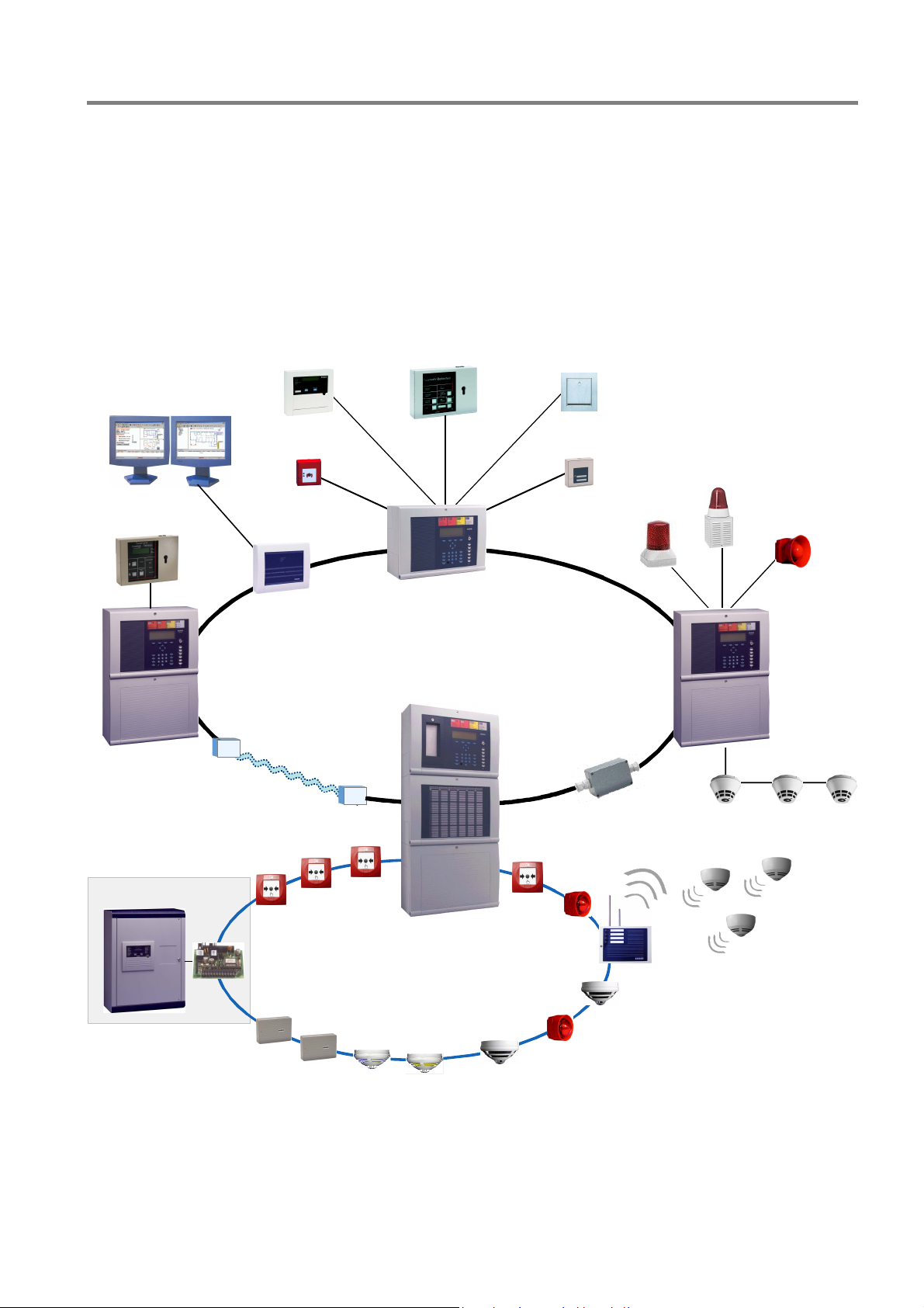
2 System overview
The modular design with different micro modules and individual extension concepts allow the Fire Alarm
Computer IQ8Control C and IQ8Control M to be easily adapted to special requirements. This provides the range
from a stand-alone panel up to 31 Fire Alarm Control Panels Computer or other network subscribers such as
supervising system WINMAG, Fire department indicator panel or Intruder Alarm Panels Series 5000 by using
the essernet
The Field device modules required in order to configure a stand-alone FACP in accordance to the appropriate
standards and guidelines. The connections for the Fire Alarm Control Panel, the master box and the three freely
programmable relays are integrated on the Field device module. If several Fire Alarm Control Panels are
connected together in the essernet
®
safety network.
WINMAG
®
LCD
display panel
MFAB
, the master box can be connected to one of the other FACPs.
FDOP
Fire dept.
key box
TAL
module
Fire department
indicator panel
Fibre optical cable
LWL
Fire alarm and extinguishing
computer 8010
essernet
Serial
®
-Interface
essernet
LWL
max. 1 km
®
max. 1 km
max. 1 km
Repeater
esserbus
Fig. 1: System overview
®
-PLus
Additional extensions
The FACP panel configuration may be extended to suit requirements by adding supplementary input/ output
modules, esserbus
®
transponders. Transponders may be installed at special integrated slots or on standard
C-Top rails in the housing. Optional plastic housings conforming to protection class IP 40 are available for the
decentralized installation of transponders on the analog loop.
FB 798951.GB0 / 01.09
7
Fire Alarm Control Panel IQ8Control C/M
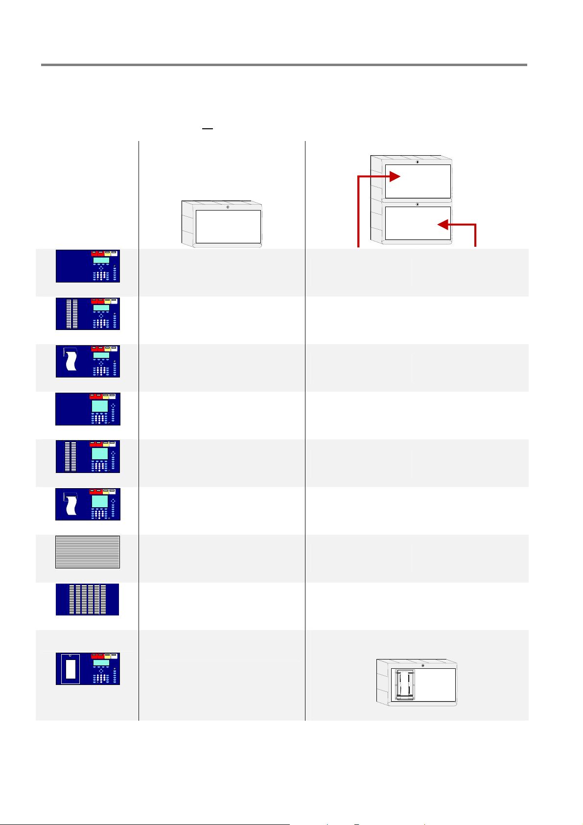
3 Configuration options
The operating module front (7860xx) is available in various language versions. The language is defined with the
2-digits of the part number, e.g. 786002
= English lettering.
IQ8Control C IQ8Control M
Operating module
7860_ _
7861_ _
7868_ _
7864_ _
7865_ _
7869_ _
9 9
9 9
9 9
9 9
9 9
9 9
---
---
---
---
---
---
742100
786000
9 9 9
9
1)
---
9
2)
9
1)
7863_ _
Fig. 2: Configuration options
1)
Extension housing required
2)
Not available for operating module 7861 _ _ or 7865 _ _
9
8 FB 798951.GB0 / 01.09
Extension housing 789304
Fire Alarm Control Panel IQ8Control C/M
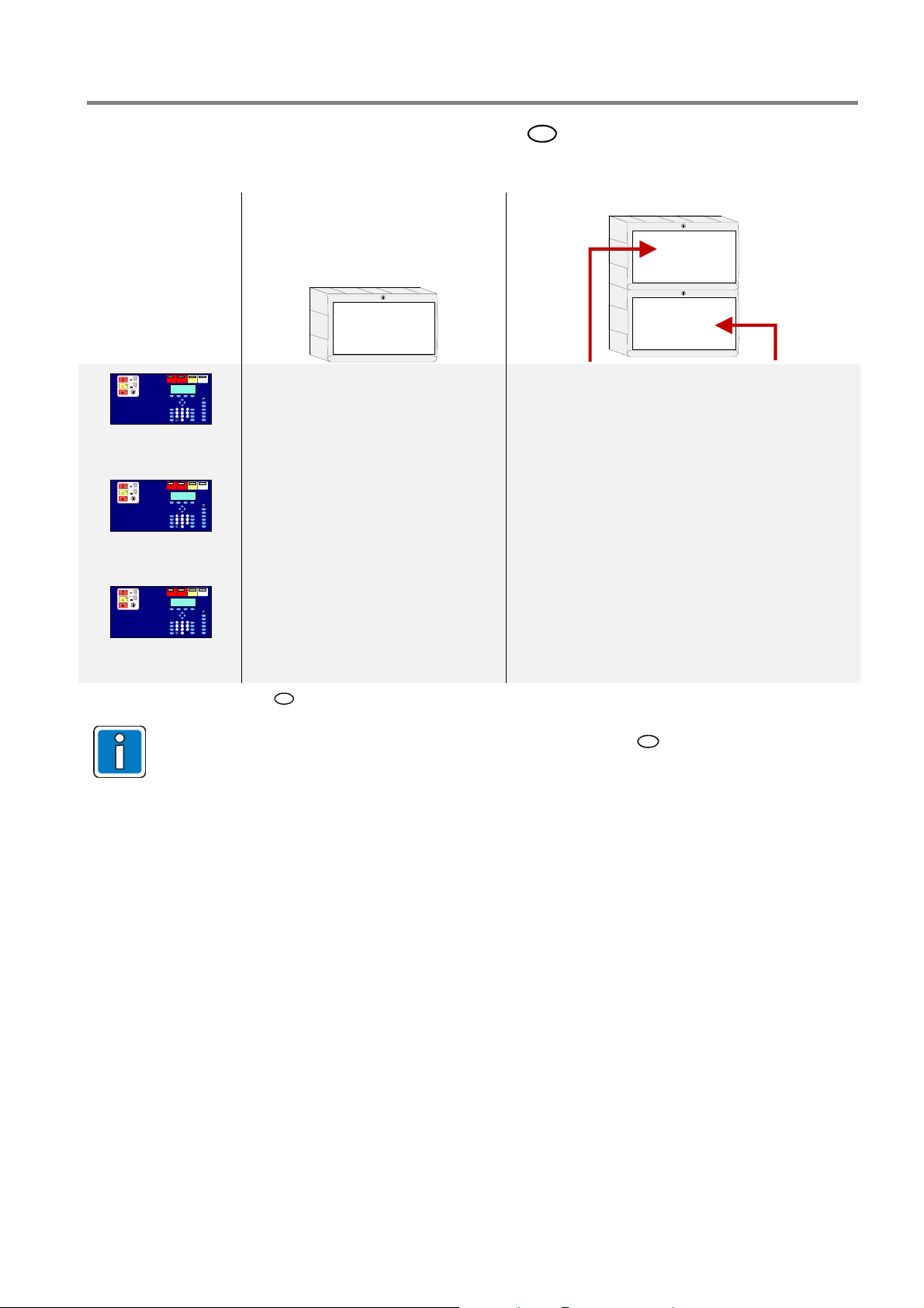
3.1 Special configuration – Swiss option CH
IQ8Control C IQ8Control M
Operating module
786261
786262
786263
Fig. 3: Operating module – Swiss CH with integrated Fire department operating panel (FBA)
For country-specific displays and labels as well as further information
instructions FACP IQ8Control C/M (Part No. 798950.GB0).
9 9
9 9
9 9
CH
refer to operating
---
---
---
FB 798951.GB0 / 01.09
9
Fire Alarm Control Panel IQ8Control C/M
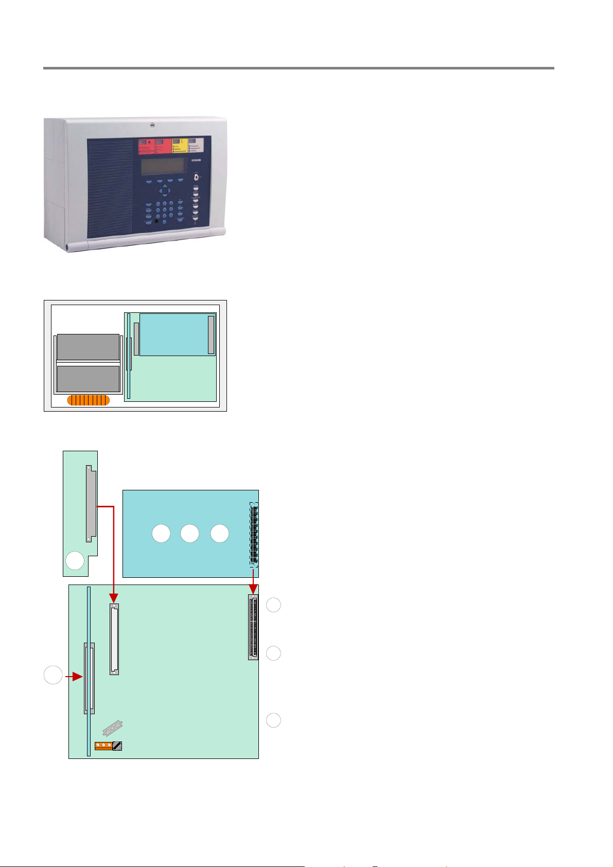
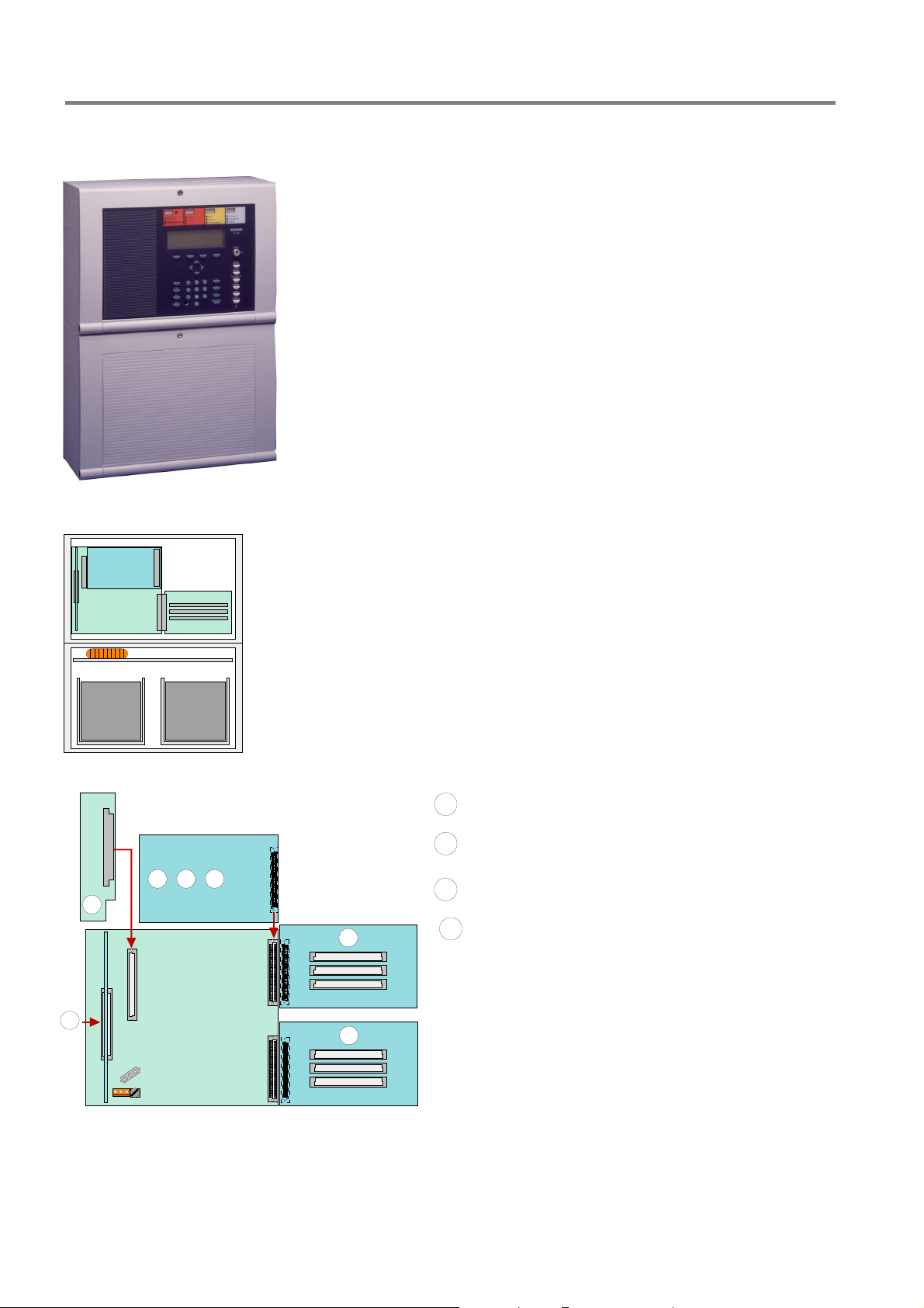
3.2 FACP IQ8Control C
The configuration of the FACP IQ8Control C includes:
1 Basic module
1 Power supply module
1 Field device module or 1 Extension module
In the full configuration, two freely selectable micro modules
can be employed.
On the Basic module only the upper slot (slot 1) of can be
used for a Field device or Extension module.
The lower slot (slot 2) of the FACP IQ8Control C is not used.
Micro module
c
A B C
Power supply module Part No. 802426
d
1
Field device module Part No. 772479
A
Connector 1
Field device module
B
with one micro module slot
Part No. 772477
2
Fig. 4: Configuration FACP IQ8Control C
Extension module
C
with one micro module slot
Part No. 772478
10 FB 798951.GB0 / 01.09
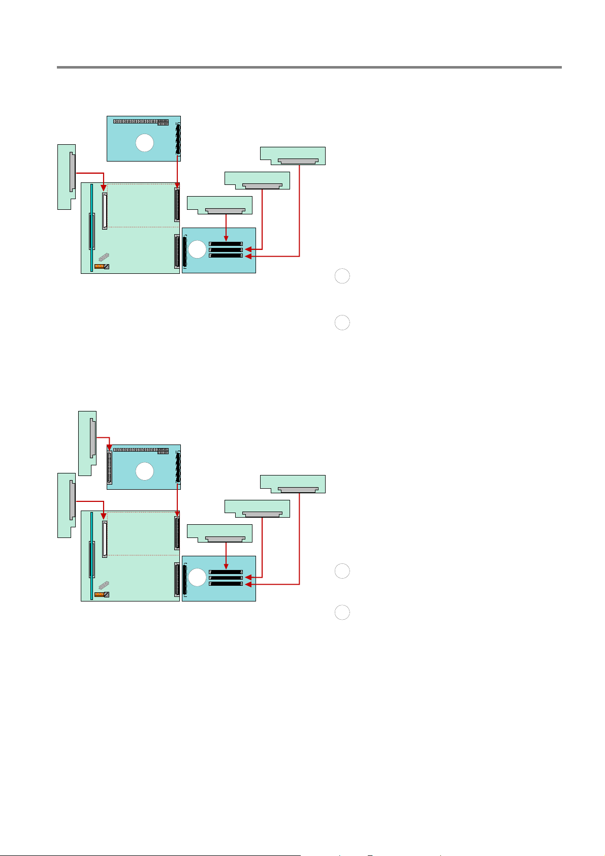
Configuration of FACP IQ8Control C
Fire Alarm Control Panel IQ8Control C/M
MM 1
MM 1
MM 2
A
B
Connector 1
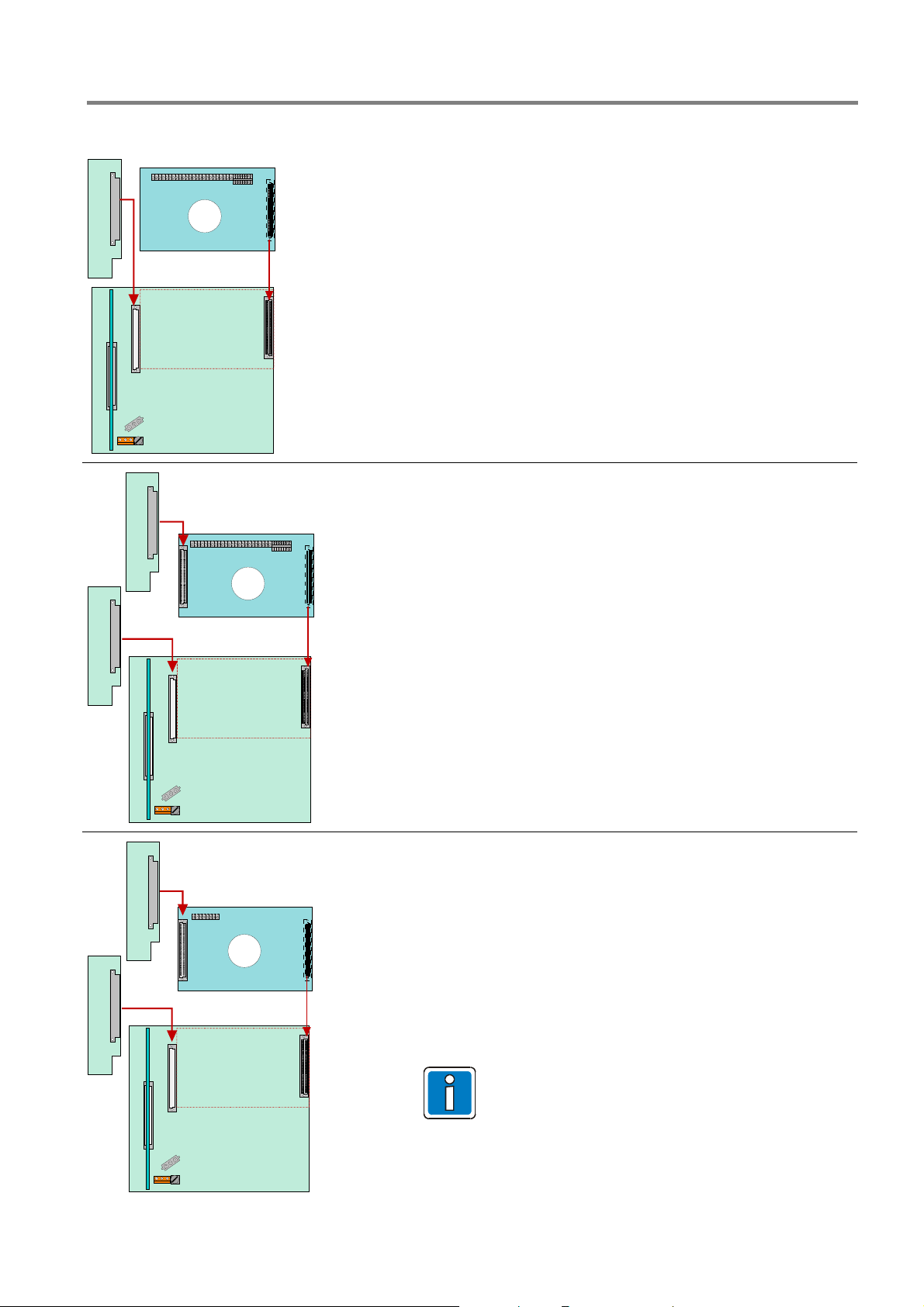
Example 1:
Basic module with a micro module and a Field device module
(Part No.772479 without micro module slot) on slot 1 of the
Basic module.
Application:
With this configuration, for example, a single control panel
with an analog loop and max. 127 bus devices can be
implemented.
Example 2:
Basic module with a micro module and a Field device module
(Part No.772477 with micro module slot) on slot 1 of the Basic
module
Application:
MM 1
MM 2
C
Connector 1
Connector 1
With this configuration, for example, a single control panel
with two analog loops and max. 254 bus devices can be
implemented
or
This configuration is usually employed in essernet
with an analog loop and max. 127 bus devices.
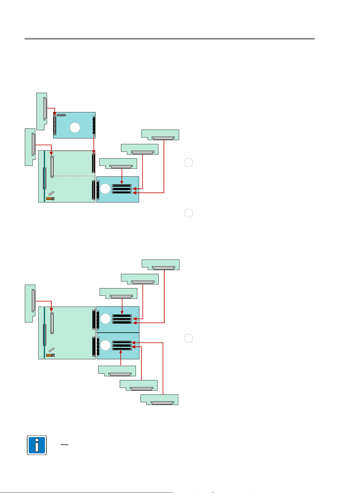
Example 3:
Basic module with a micro module and a Extension module
(Part No.772478 ) on slot 1 of the Basic module.
Application:
This configuration is usually employed in essernet
with an analog loop and max. 127 bus devices.
Without the Field device module, no connection is
available for the fire department key pad and the
master box. These devices can be connected to a
different control panel of the essernet
®
networks
®
networks
®
.
Fig. 5: Configuration FACP IQ8Control C
FB 798951.GB0 / 01.09
11
Fire Alarm Control Panel IQ8Control C/M
3.3 FACP IQ8Control M
The configuration of the FACP IQ8Control C includes:
1 Basic module
1 Power supply module
1 Field device module or 1 Extension module 1
or
max. 2 Extension modules - each with three micro
module slots
In this full configuration, a total number of slots for 7
(3 + 3 + 1) freely selectable micro module are available.
A B C
1
Slot 1
On the Basic module only the upper slot (slot 1) can be
used for a Field device or Extension module.
The Field device module must be installed in Slot 1 of
the Basic module.
Slot 2
The lower slot (slot 2) can be used for a Extension
D
module only.
Field device module Part No.772479
A
Field device module with one
B
additional micro module slots
Extension module with one
C
additional micro module slots
Extension module with three
D
additional micro module slots
Part No.772477
Part No.772478
Part No.772476
Connector 1Connector 2
2
D
Fig. 6: Configuration FACP IQ8Control M
12 FB 798951.GB0 / 01.09
Example: Configuration of FACP IQ8Control M
Fire Alarm Control Panel IQ8Control C/M
Example 1:
MM 1
MM 2
A
Basic module with a Field device module
MM 4
(without micro module slot) on slot 1 and one
Extension module (with 3 micro module slots)
MM 3
on slot 2.
MM 2
Connector 1
Application:
With this configuration, e.g. a single control
panel with 4 analog loops and max. 508 bus
D
Connector 2
devices can be implemented.
Field device module (Part No.772479)
A
Extension module with three additional micro
D
module slots (Part No.772476)
Example 2:
MM 1
B
D
Connector 2 Connector 1
Fig. 7: Configuration FACP IQ8Control M
MM 3
MM 4
MM 5
Basic module with a Field device module
(without micro module slot) on slot 1 and one
Extension module (with 3 micro module slots)
on slot 2.
Application:
With this configuration, e.g. a single control
panel with 5 analog loops and max. 635 bus
devices can be implemented
Field device module with 1 additional micro
B
module slot (Part No.772477)
Extension module with three additional micro
D
module slots (Part No.772476)
FB 798951.GB0 / 01.09
13
Fire Alarm Control Panel IQ8Control C/M
Example: Configuration of FACP IQ8Control M
MM 2
MM 1
C
MM 4
MM 3
D
Connector 2 Connector 1
MM 5
Example 3:
Basic module with a Field device module
(without micro module slot) on slot 1 and
one Extension module (with 3 micro module
slots) on slot 2.
Application:
With this configuration, e.g. a security
network panel with 4 analog loops and max.
508 bus devices can be implemented.
Extension module with one additional micro
C
module slot (Part No.772478)
MM 1
Extension module with three additional micro
D
module slots (Part No.772476)
MM 4
MM 3
MM 2
Example 4:
Basic module with two Extension modules
(with 3 micro module slots) on slot 1 + 2.
Application:
With this configuration, e.g. a security
network panel with 6 analog loops and max.
D
762 bus devices can be implemented.
Extension module with three additional micro
D
module slots (Part No.772476)
D
Connector 2 Connector 1
MM 5
MM 6
MM 7
Fig. 8: Configuration FACP IQ8Control M
install Field device and Extension modules series 01 FACP 8000 C/M (Part No. 772418, 772419,
Do not
772420, 772421) at FACP IQ8Control C/M.
14 FB 798951.GB0 / 01.09
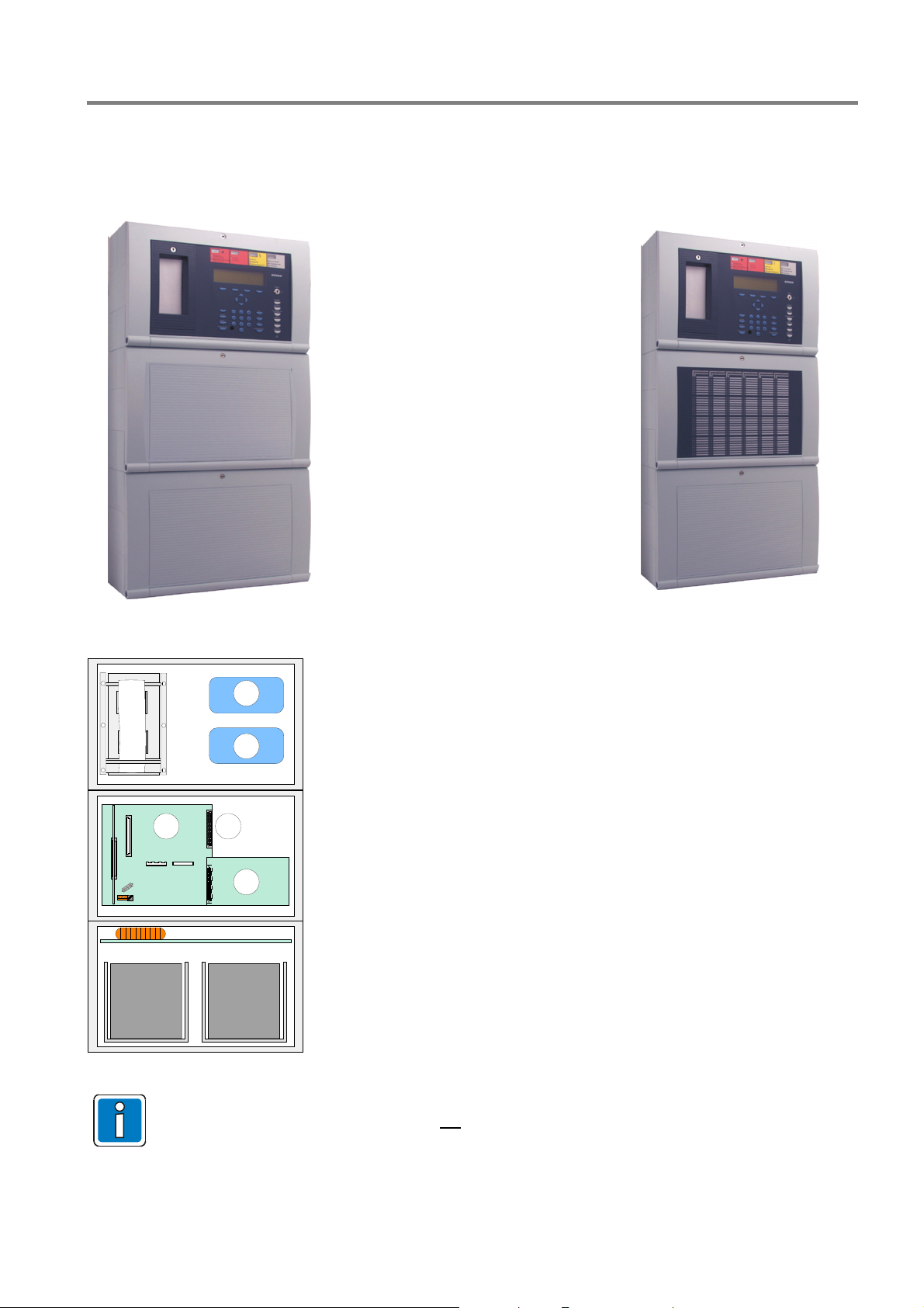
Fire Alarm Control Panel IQ8Control C/M
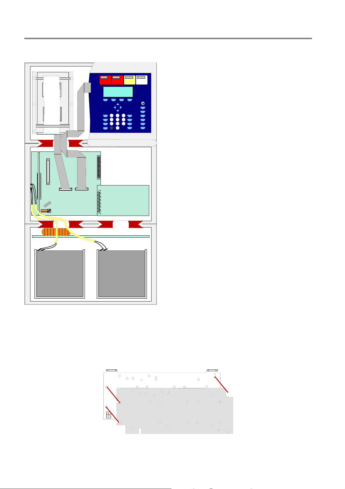
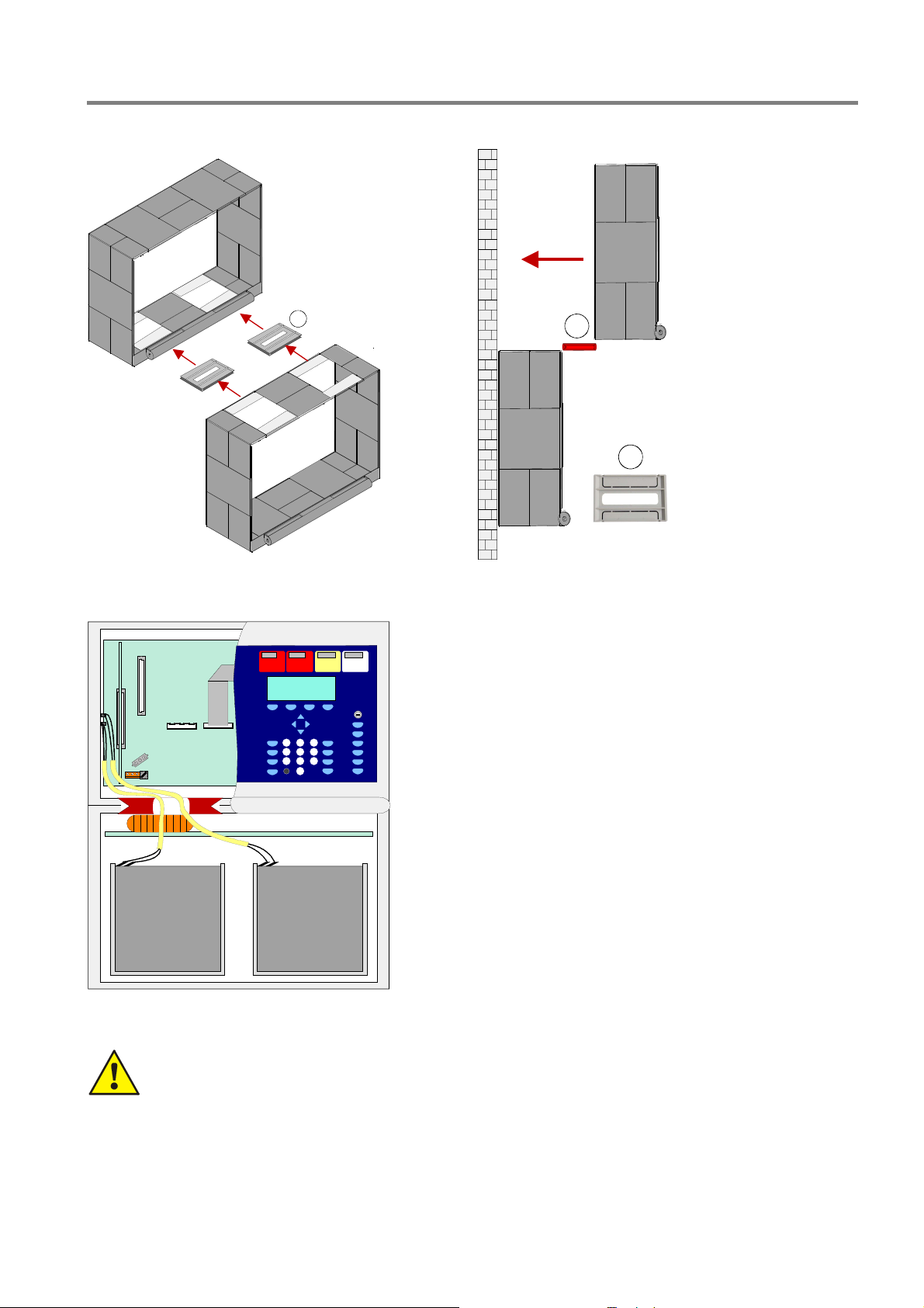
Three part housing with integrated printer
The integrated printer and the operating module front are mounted in the upper housing. Due to the depth of the
printer, the Basic module and all of the plug-in cards are integrated into a separate housing beneath. The
emergency power supply with max. two 24Ah batteries can be installed into the lowest housings.
Extension housing 789304
or
Extension housing 789303
Fig. 9: Three part housing with integrated printer
Assembly area for esserbus® transponders
1
1
2
Fig. 10: Location of the components in a three part housing
Ensure that the arrangement of the assemblies corresponds with the presentation shown here during
this configuration. Another distribution is not
front, the integrated printer and the battery connection cable.
3
4
c
Basic module / power supply module /
d
slot for micro module
Alternatively Field device module
e
(without micro module slot)
or Field device module (with 1 micro module slot)
or Extension module (with 1 micro module slot)
or Extension module (with 3 micro module slots)
on slot 1
Extension module (with 3 micro module slots)
f
on slot 2
Part No. 772479
Part No. 772477
Part No. 772478
Part No. 772476
Part No. 772476
possible due to the cable length of the operating module
FB 798951.GB0 / 01.09
15
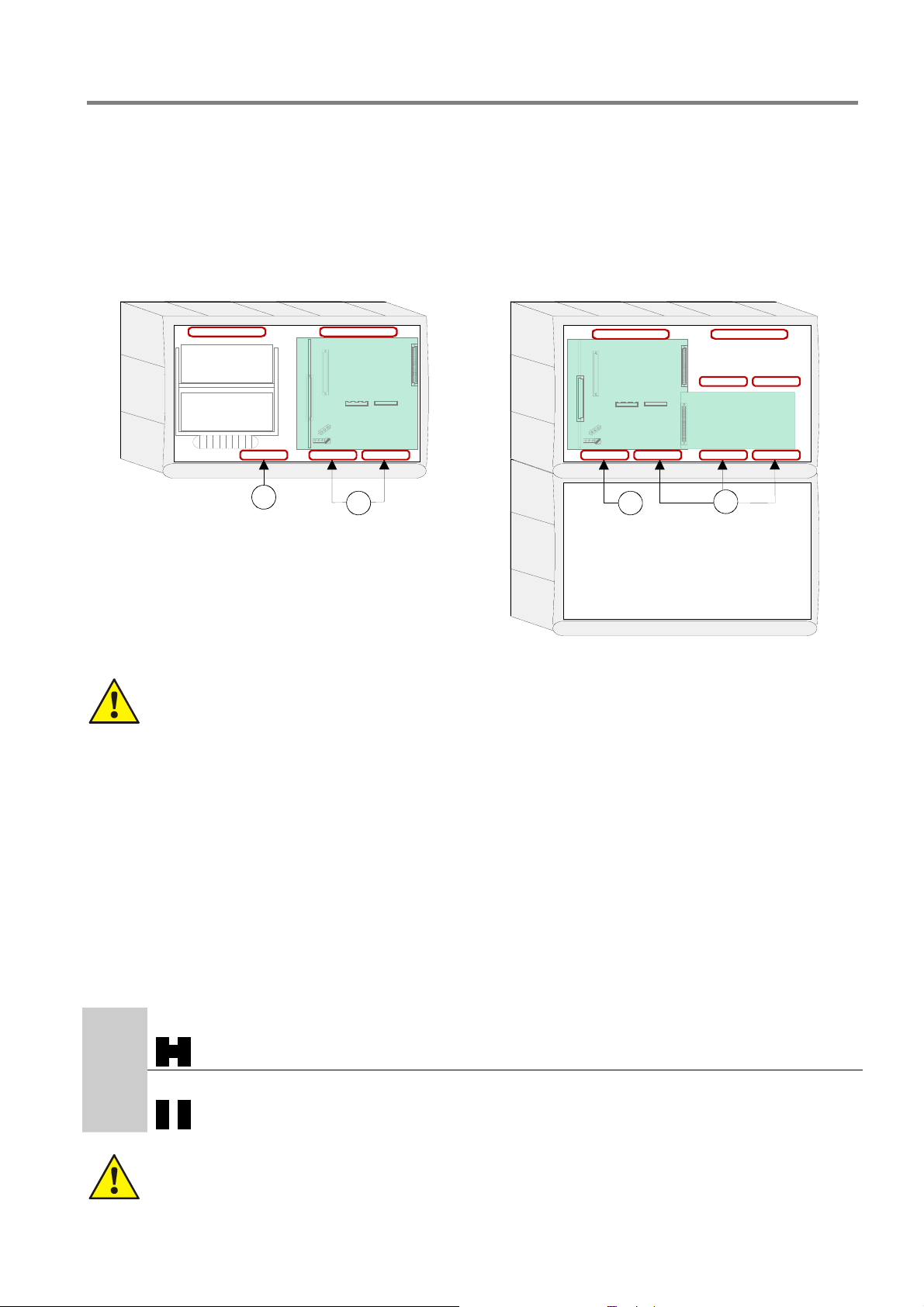
Fire Alarm Control Panel IQ8Control C/M
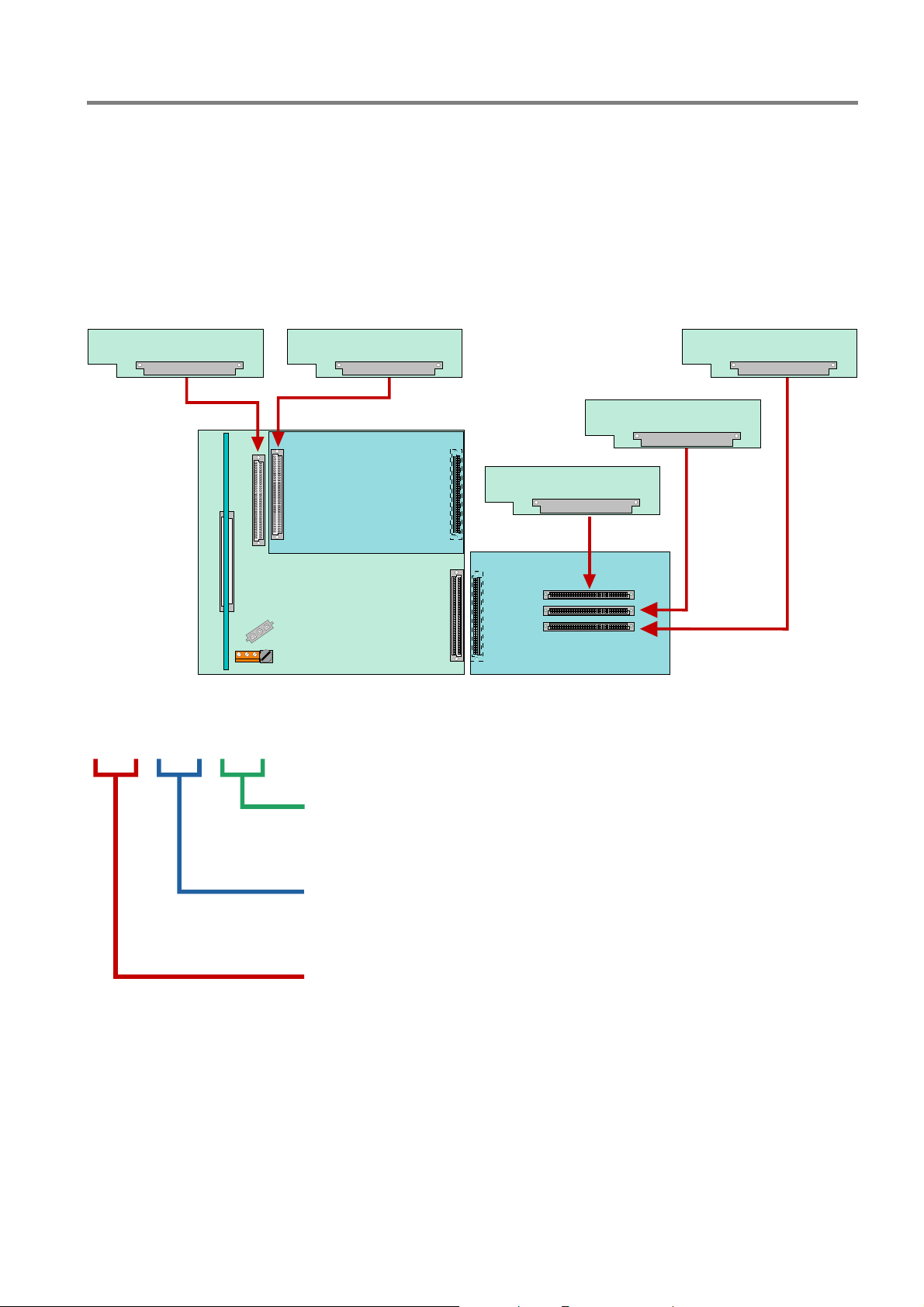
Location of the components in a three part FACP housing IQ8Control M
Fig. 11: Location of the components in a three part housing
Mounting plate for master boxes DS 7500 / DS 8800
The mounting plate (Part No. 057633) allows installation of two esserbus
®
transponders or one master box Type
DS 7500 / DS 8800 in the extension housing (Part No. 789303).
Protect the devices against short circuits with the metal mounting plate with the plastic spacers and the
insulation foil.
Mounting plate
Insulation foil
Fig. 12: Mounting plate (Part No. 057633)
16 FB 798951.GB0 / 01.09
Fire Alarm Control Panel IQ8Control C/M
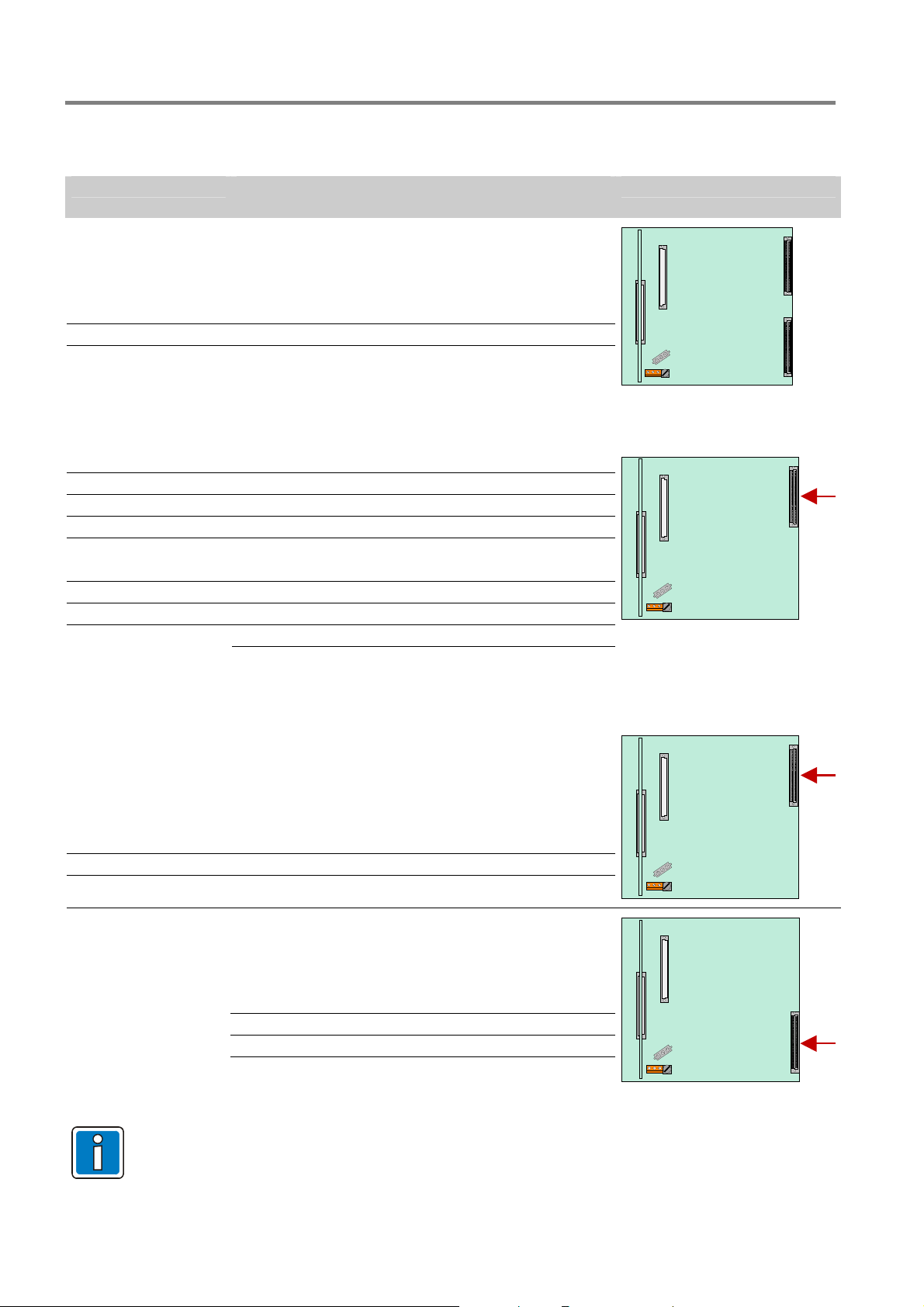
3.4 Definition of the Primary loop number
Individual assemblies of the FACP IQ8Control can be switched on/off with the internal primary loop number
through the control panel keyboard or programmed with programming software . This internal primary loop
number is composed of the control panel number, the slot and the assembly number.
Example: Stand-alone FACP (= Panel No. 01)
0113 0123 0133
0132
0131
Fig. 13: FACP IQ8Control
0 1 X X
2
1
3
Subassembly number of the Basic-, Field device or Extension module
(ref. follow pages)
Slot number: Basic module = No. 1
Basic module Slot 1 = No. 2
Basic module Slot 2 = No. 3
(only FACP IQ8Control M)
Number of the Fire Alarm Control Panel
Stand-alone FACP = 01
Security network FACP = 01 - 31
FB 798951.GB0 / 01.09
17
Fire Alarm Control Panel IQ8Control C/M
Example: Primary Loop No. (Panel No. 01)
Primary Loop No. Subassembly
Basic module
0111
0112
0113
Field device module
0121
0122
0123
0124
Extension module with 1 micro module slot Part No. 772478
---
---
0123
---
Common Fault Relay (SaS-Relay)
Interface - RS485-1 or TTY
Micro module slot
Relay K2, K3 and K4
Master box (MB) Relay K1
Micro module slot (only module Part No. 772477)
Internal primary loop
no module available
no module available
Micro module slot
no module available
Position of modules
Connector 1Connector 2
Connector 1
Extension module
(only IQ8Control M)
0121
0122
0123
Extension module
(only IQ8Control M)
0131
0132
0133
The Field device module (if available) must be installed in >Slot 1< of the Basic module.
>Slot 2< of the Basic module is unused on the FACP IQ8Control C.
with 3 micro module slots Part No. 772476
Micro module slot 1
Micro module slot 2
Micro module slot 3
with 3 micro module slots Part No. 772476
Micro module slot 1
Micro module slot 2
Micro module slot 3
Connector 1
Connector 2
18 FB 798951.GB0 / 01.09

Fire Alarm Control Panel IQ8Control C/M
3.5 Central housing
1. Remove the central housing of the FACP IQ8Control from the box.
The cover contact and both connecting cables for the rechargeable batteries have already been attached to
the Basic module.
2. Pull the ribbon cable of the operating module and of the built-in printer (if present) off the connectors of the
Basic module.
3. Remove the four connecting screws between the base plate and the housing frame which were screwed in
for transport.
4. The housing door (operating module and variants) has already been connected to the housing frame at the
factory. To detach the housing door from the housing frame, pull out both retaining pins of the housing door
holder.
5. The housing must be mounted on a stable, clean and dry wall surface without mechanical stress. The
function of the snap-type connection for the housing door can be impaired if the housing is not correctly
mounted.
Only flat-head screws and dowels with a diameter of 8 mm should be used to secure the central unit’s
housing. Here, make sure that the screw head fits into the hole of the wall compensation element and does
not project.
6. To compensate for slight wall unevenness, you can screw the four wall compensation pieces of the base
plate in or out. The central unit’s additional pack contains a special spanner for the adjusting the wall
compensation elements.
The three unused fastening points between the base plate and the housing frame are not necessary on the
FACP IQ8Control C/M. This fastening is intended for a different housing use.
Danger - Electrical shock !
Disconnect all power from the panel before carrying out any installation work. The panel may only be
operated while the cabinet is closed. Operation is not allowed while the cabinet is open.
Risk of short circuit
All voltage and signal lines connected to the Basic module must be secured to prevent slipping by
using a suitable attachment materials such as plastic cable binders. Make sure the voltage cable will
not move and touch the signal lines (SELV). Work on the FACP IQ8Control may only be carried out
when it is de-energised (mains and emergency power supply).
FB 798951.GB0 / 01.09
19
Fire Alarm Control Panel IQ8Control C/M
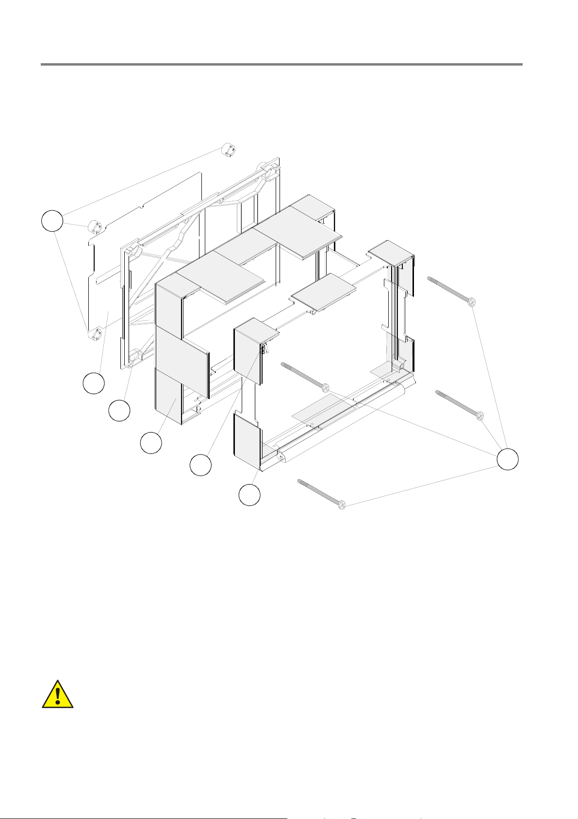
3.6 Assembly
The housing is pre-assembled by factory delivery. To ease the further assembling and mounting please observe
the given mounting sequence.
1
2
3
Fig. 14: Exploded illustration
c
d
e
f
g
h
i
4x wall compensation pieces
1 x Metal sheet of the base plate for shielding and the PE connection (functional earth)
1x rear panel
1x back box
1x housing contact (up to four contacts possible)
1x front frame with operating module and housing door
4x connecting screws
The Basic module is connected to the central housing’s rear metal panel via the metal spacers and
the metal screws. Without this electrically conductive connection between the Basic module and the
rear metal panel, sufficient EMC protection for the FACP IQ8Control is not guaranteed.
4
5
7
6
20 FB 798951.GB0 / 01.09
Fire Alarm Control Panel IQ8Control C/M
Operating module / Housing door
The operating module/the housing door is installed by the manufacturer on the front housing part. If required for
dismantling, loosen the 4 fixing screws and remove the front part of the housing.
Depending on the panel configuration, e.g. with or without an installed printer or an individual zone display,
deviation from the illustration here is possible.
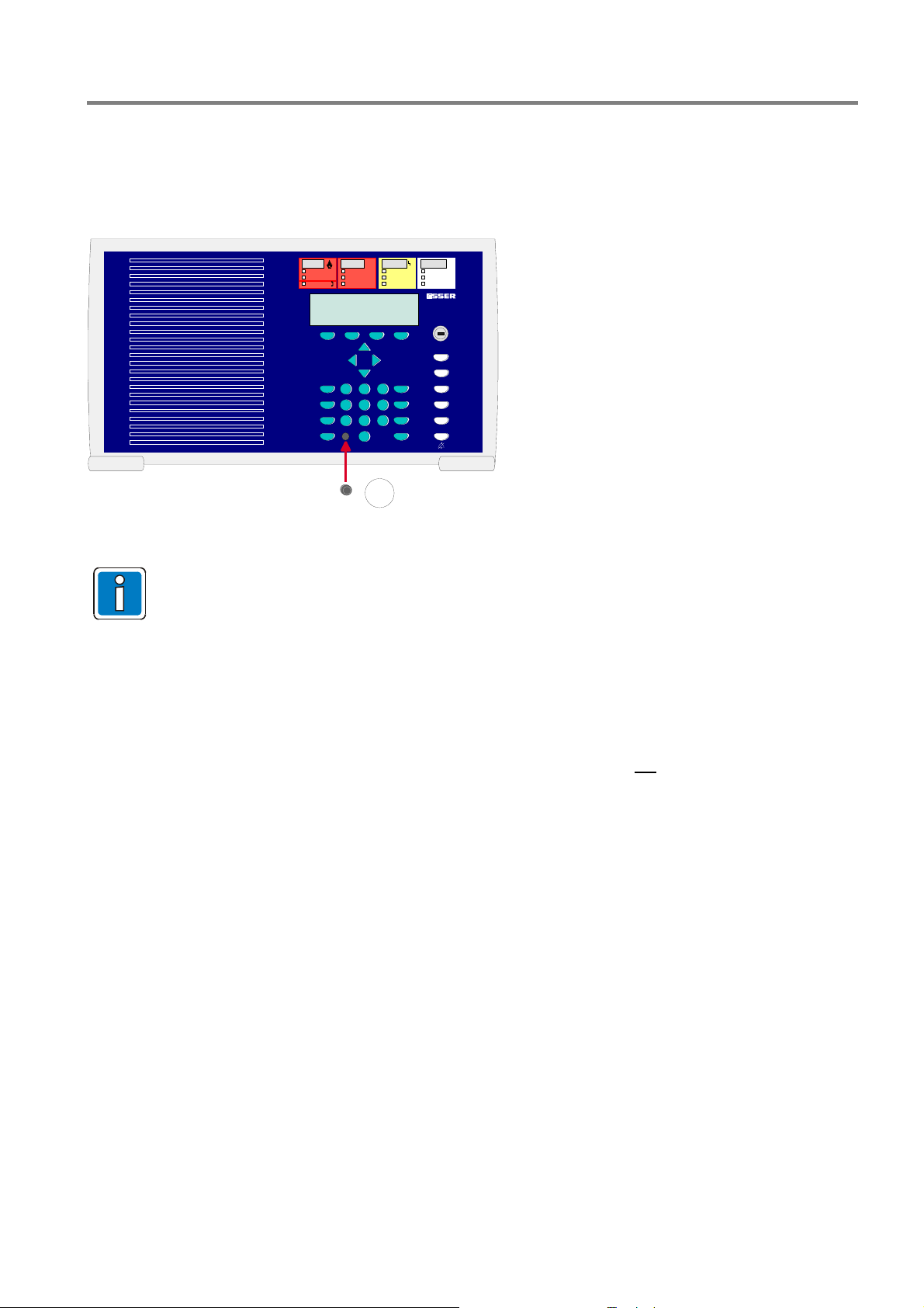
For correct ESD protection it is highly
recommended to insert the dummy plug
123
456
789
0
(insert pack) of the programming interface
plug into front of the operation panel.
8
Fig. 15: Operating module / Housing doo
The operating module is not required for programming the FACP IQ8Control. The service PC can
also be directly connected to the programming connector of the Basic module. Using the service
program TEDIS (optional) enables the operating module to be completely simulated on the service
PC with all functions.
Opening
The front door key is always required to open the housing front.
It can be opened with the key vertical
Closing
To close the front door, the lock must be in the horizontal position. The key is not
required. The front door can
simply be pushed closed and engaged in the snap-type fastener.
Example: Housing IQ8Control C
1. Place front frame with integrated door carefully onto the back box.
Take care to ensure that no cables are pinched or damaged when installing or removing the assembly.
2. Insert the four screws between the back box and the front frame and tighten carefully.
3. Insert housing contact in the upper place of the housing with the contact tab downwards. The contact is
connected to the Basic module by factory settings and may be removed for service or maintenance work.
4. Connect the ribbon cable of the operation panel to the corresponding connector on the Basic module.
5. This completes assembly of the housing
FB 798951.GB0 / 01.09
21
Fire Alarm Control Panel IQ8Control C/M
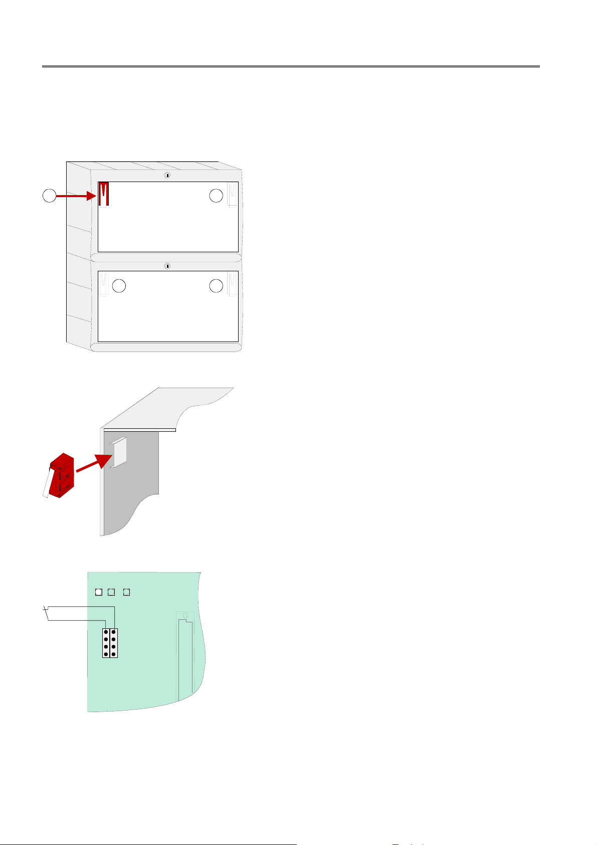
Housing contact
The housing contact provides the monitoring of the panels housing and may be used additionally for control
function by means of service or maintenance work, e.g. to disconnect devices whilst the contact is open.
Max. 2 contacts per housing
(1 integrated contact by factory configuration)
1 1
Max. 4 contacts per FACP
Select contact operation via the panels data
configuration, e.g.
- Disconnect master box whilst open contact
- Access of Service-PC whilst open contact
- und additional features
11
The housing contact must be place to the appropriate
insert on the top corner of the housing.
Housing contact / contact tab points downwards
Housi ng
open
V2
8
7
6
5
X7 X8
1
2
3
4
Housing contact
Connect to Basic module
(refer to section “Basic module”)
Fig. 16: Housing contact
22 FB 798951.GB0 / 01.09
Fire Alarm Control Panel IQ8Control C/M
Connection between the central housing and the extension housing
1
1. Remove the appropriate 2 plastic plates from
panels and extension housing
2. Push the plastic connector bracket in each
originated gap. Observe the arrows on the bracket
for the right direction.
1
1
2x connection pieces
with cable glands
Fig. 17: Knockouts for battery cable
Damage to the system!
Take care to ensure that no cables are pinched or damaged.
Each housing part must be separately fixed to the mounting place. The plastic connection brackets are
not suited to carry the weight of the lower housing alone.
3. Push the upper housing via the guide way of the
brackets towards the wall.
4. Align both connection brackets to ensure that the
cables between the housings may be lead through
the openings of the brackets.
5. Each housing must be fixed with suited screws
(4x) and dowels without twisting stress.
FB 798951.GB0 / 01.09
23

Fire Alarm Control Panel IQ8Control C/M
Wall mounting
The panel must be mounted on a flat surface using appropriate hardware (screws and dowels). Avoid
mechanical stressing. It may only be commissioned after correct mounting on a wall or other mounting surface
of sufficient strength to support the weight of the unit. Minor unevenness of the mounting surface may be
adjusted by the wall compensation device. Apply the delivered key tool from the inside of the housing to adjust
the wall compensation devices.
1
Fig. 18: Rear side of the Standard back box
Fig. 19: Wall compensation element for adjusting and key tool
Damage to the system !
Please note that depending on the rechargeable batteries used, a significant weight must be
supported by the fastening screws of the extension housing.
Plastic key is enclosed.
24 FB 798951.GB0 / 01.09
Fire Alarm Control Panel IQ8Control C/M
3.7 Cable glands
Lead the 230V main power cord through the wall and the cable entry c provided in the rear of the unit (see
illustration). Fasten it using appropriate devices, e.g. plastic cable straps.
Make sure that the mains and signal cables don’t interfere with the rear panel of the cabinet or the cabinet frame
which is mounted on the rear panel.
Signal cables must only be led through the other cable entries
IQ8Control C
d.
IQ8Control M
1
Fig. 20: Cable glands
Danger - Electrical shock !
Disconnect all power from the panel before carrying out any installation work. The panel may only be
operated while the cabinet is closed. Operation is not allowed while the cabinet is open.
Risk of short circuit
All voltage and signal lines connected to the Basic module must be secured to prevent slipping by
using a suitable attachment materials such as plastic cable binders. Make sure the voltage cable will
not move and touch the signal lines (SELV). Work on the FACP IQ8Control may only be carried out
when it is de-energised (mains and emergency power supply).
Insulation of connecting cable
Make sure to lead all cables complete with their outer sheaths intact into the cabinet. Only remove the
insulation from those sections which are inside the cabinet.
3.8 Panel buzzer
2
1
2
If required the internal panel buzzer may be disabled with the solder jumper BR2 on the rear side of the
operating panel PCB.
BR2
BR2
closed, buzzer enabled (factory setting)
BR2
open, buzzer disabled
If the buzzer is permanently disabled (BR2 open), the transmission of this audible warning signal to
must be ensured (e.g. by indicating this condition at a panel within the network)!
FB 798951.GB0 / 01.09 25
Fire Alarm Control Panel IQ8Control C/M
4 Module
The FACP IQ8Control C / M has a modular design so that modules can be replaced/extended at any time.
Only remove or insert modules when the FACP is voltage free.
Switch off the power and battery supply.
Wait for at least 10 seconds before the modules are replaced or supplemented.
Take suitable measures to discharge static electricity.
Check correct installation (modules and connection cables).
Switch on the power and battery supply.
If necessary, check/supplement the customer data using the programming software tools
8000.
4.1 Power supply module (Part No. 802426 index G or higher)
The power supply module is installed on the Basic module of the FACP. This module accommodates the entire
voltage supply for the Fire Alarm Control Panel and the +12 V DC supply voltage for external devices. Maximum
current load from external users will depend on control panel configuration. If necessary, additional supply is
possible from a monitored external power supply unit. The power supply module is suited to connect 2 batteries
(2 x 12 V / 24 Ah). In case of an AC power (230 V DC) loss the panel operation will be supplied without
discontinuation (refer chapter 4.1.3).
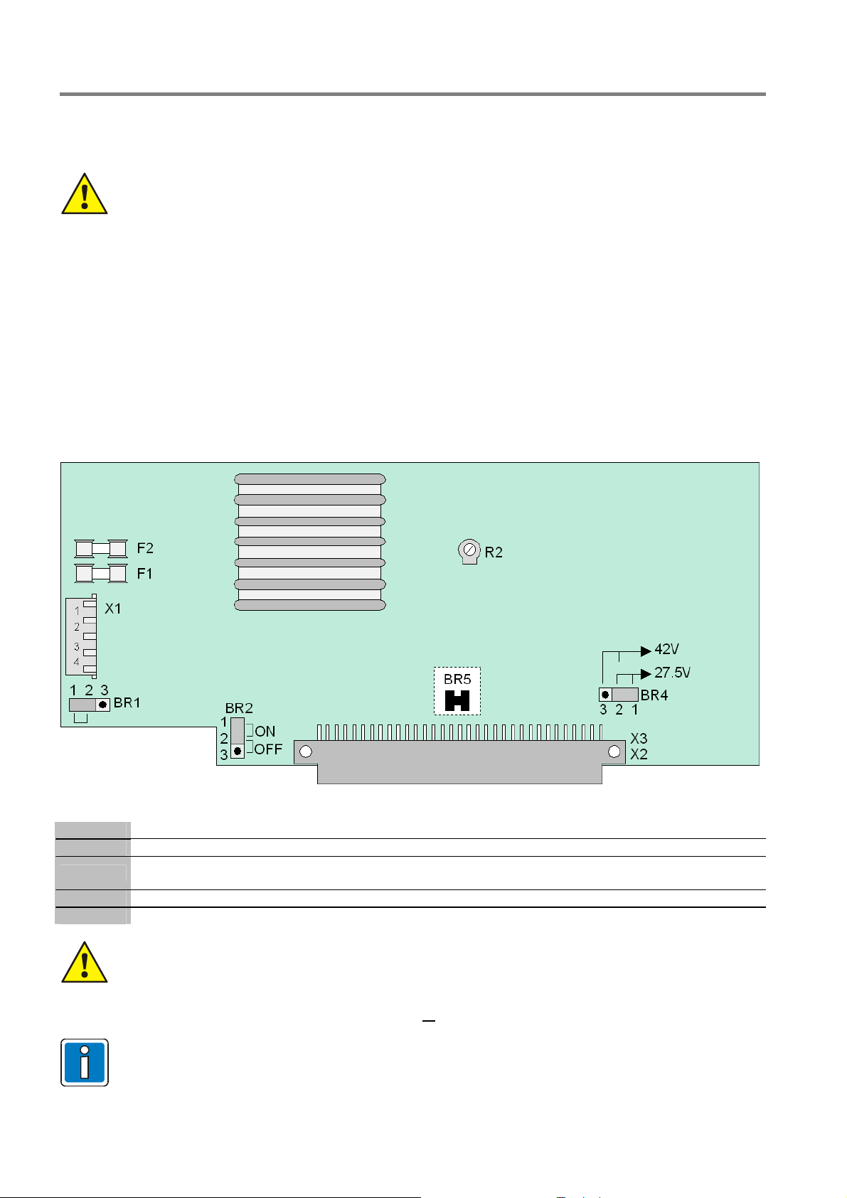
Fig. 21: Power supply module (Part No. 802426 from index G)
X1
X 2/3
F1
F2
R 2
Plug connector for transformer (secondary)
Basic module connector
Fuse for the FACP internal power supply: T 4 A
to the analog loop 27,5 V (esserbus
Fuse for secondary side: T 5 A
Potentiometer for adjusting the battery charging voltage to +13.65 V DC (@ 25 °C)
The power supply module must only be installed or removed with the Fire Alarm Control Panel in a
de-energised state.
When you are installing or replacing the power supply module, observe the BR5 solder
bridge/jumper (on the rear side of the circuit board). This jumper is used to set whether the power
supply unit is installed in an FACP 8000C/M or
this could damage the Fire Alarm Control Panel or the power supply unit.
The battery charging voltage is set to the abovementioned values by the manufacturer. If the FACP
is used at other ambient temperatures (refer to technical data), then the battery charging voltage
must be adjusted accordingly using potentiometer R2.
®
) or 42 V (esserbus® PLus)
an IQ8Control C/M. If the jumper is set incorrectly,
26 FB 798951.GB0 / 01.09
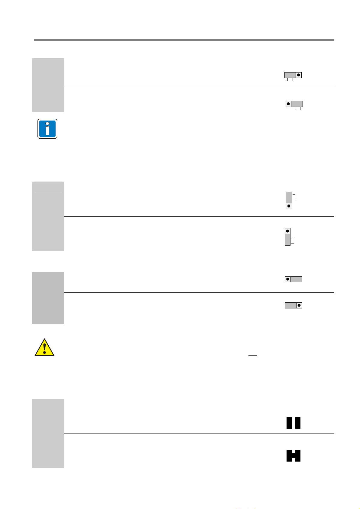
Earth fault monitoring
Fire Alarm Control Panel IQ8Control C/M
BR 1
Earth fault monitoring enabled (factory default = ON)
Earth fault monitoring disabled (not VdS appropriate)
Information for powered loop systems
In case of an earth fault with +U
message "U
<" will be displayed for each analog loop. In the alarm condition, the zone voltage
zone
is lower than the required 42 V. The audible alarm loop device may not sound an alarm at full
volume.
Undervoltage protection (U
BR2
Undervoltage protection activated (factory setting = ON)
The panel switches off automatically if, in case of charging, the
battery voltage is
Under voltage protection disabled
< 9,5 V DC)
Batt
9.5 DC.
ON
1 2 3
OFF
1 2 3
a ground fault message occurs and additionally the fault
zone
1
ON
2
3
1
2
OFF
3
Selection of the analog loop voltage
BR 4
esserbus® System with 27,5 V analog loop voltage
esserbus® PLus System with 42 V analog loop voltage
esserbus
devices with Part No.
®
PLus module Part No. 804382 and appropriate loop
80xxxx required
Damage to the system !
Mixed operation with esserbus® and esserbus® PLus functionality is not possible!
Selection of the Fire Alarm Control Panel
Solder jumper on the rear side of the PCP to select the CPU power supply voltage.
BR5
Factory default of a separately delivered power supply module
(Prepared for mounting in the FACP 8000 C / M)
3 2 1
3 2 1
BR5
Operation in FACP IQ8Control C/M Î Jumper BR 5 closed
BR5
FB 798951.GB0 / 01.09 27
Fire Alarm Control Panel IQ8Control C/M
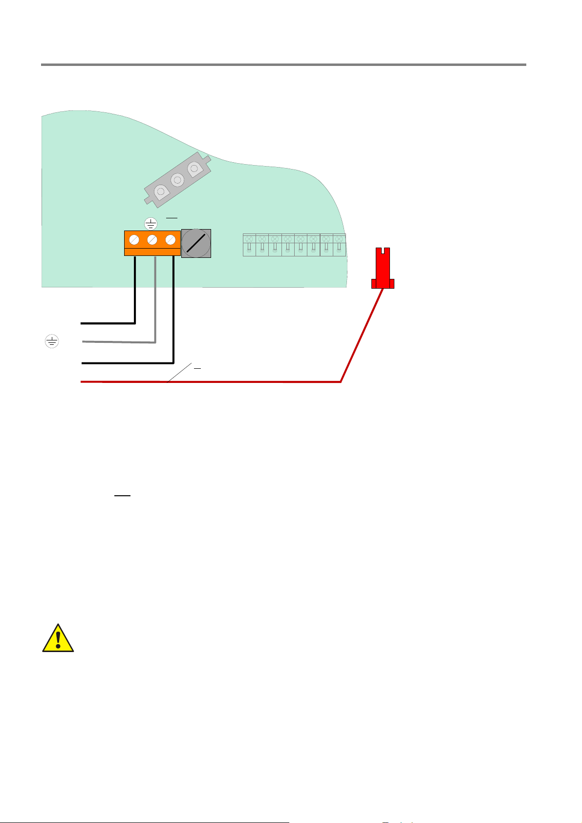
4.1.1 Mains connection and earth connections
L1
F1
T1.25A
H/230V~
X2
N
U
Main
230V~
N
Housing mantle
terminal
PE
L1
FE
Fig. 22: Connection of the rated voltage (230 V AC) and earth connections on the basic module
The mains supply must be installed in accordance with local regulations by a qualified technician. The AC
connection terminals are located on the Basic module.
Requirements
Use an appropriate mains cable, e.g. NYM 3 x 1.5 mm2 or a cable type with similar specifications.
The installation must comply with local regulations on electrical safety.
Overvoltage fine protection is integrated into the FACP according to EN 54 and the VdS guidelines. Should
coarse protection be required this should be installed by the installer for the specific object.
The fire alarm system must be supplied from the 230 V mains through a separate isolator or an
appropriately labelled safety switch. The required mains voltage (230 V AC) is given on the panels
nameplate.
In buildings fitted with earth fault devices (FI protection), a separate device must be installed for the fire
alarm system.
The fuse for the power supply of the fire alarm system must be clearly labelled with the red marking ‘FACP’.
Observe national standards and guidelines.
The protective earth conductor of the mains cable must be connected to the corresponding screw terminal
at the fire alarm panel (ref. to section Protective and Functional earth).
AC mains voltage
Cable corss section at least
> 4mm² to PE rail
The required mains voltage (230 V AC) is given on the panels nameplate.
Cable insulation
Make sure to lead all cables complete with their outer sheaths intact into the cabinet. Only remove the
insulation from those sections which are inside the cabinet!
Power supply
The fuses of the panel or external power supply units cannot prevent an unexpected fault in electrical
modules; rather, these fuses are intended to protect users and their surroundings from damage.
Therefore, never repair or bridge the fuse that is installed (e.g. T1A H/250V) or replace it with anything
other than the stated type!
28 FB 798951.GB0 / 01.09
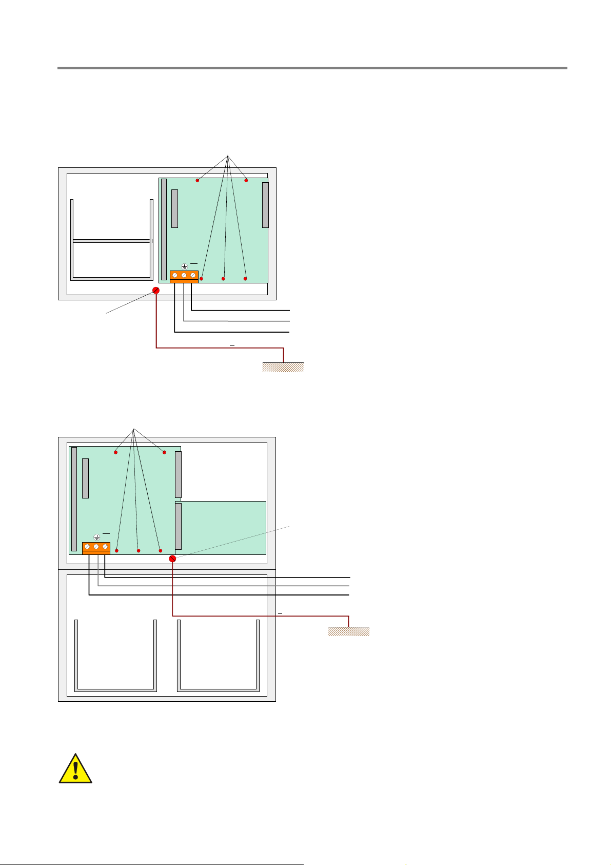
4.1.2 Protective and Functional earth
Fire Alarm Control Panel IQ8Control C/M
Wiring FACP IQ8Control C
rear wall plate of the central unit's housing
Battery bag 2
Battery bag 1
Housing mantle terminal
Basic
module
N
Cable cross section at least > 4mm² to PE rail
Wiring FACP IQ8Control M
Metal screws to the
rear wall plate of the central unit's housing
Metal screws to the
L1
U
L1
PE
N
FE
The primary PE-connection (protective
earth) of the mains supply must be
connected to the appropriate terminal of
the FACP to ensure a proper operation of
the system.
The FE (functional earth) and PE
(protective earth) terminals of the panel’s
housing must be connected with the PE
rail of the power distributor panel from
which the fire alarm system will be
powered.
Use copper cable with a cross section of
at least ≥ 4 mm
2
depending on the length
of the cable run.
The FACP IQ8Control is a protection
>class I DIN EN 60950< device.
Basic
module
L1
U
N
Battery bag 1
Fig. 23: Protective and Functional earth
The base module is connected to the rear panel of the cabinet by means of metal spacers and
screws. This electrically conducting connection between base module and rear panel is essential
for correct functional earthing of the FACP IQ8Control C/M.
Battery bag 2
Housing mantle terminal
Cable cross section at least
> 4mm² to PE rail
L1
PE
N
FE
FB 798951.GB0 / 01.09 29

Fire Alarm Control Panel IQ8Control C/M
Several alarm circuits on one power supply unit
If several visual/acoustic alarm devices are switched on e.g. via the 3 relay micro module (part no.
787531), 4 relay micro module (part no. 787530), the 4 zone/2 relay esserbus
no. 808613/808613.10) or the 12 relay esserbus
their power supply is provided by a joint power supply unit
®
transponder (part no. 808610/808610.10) and
, then the installer must ensure that there
®
transponder (part
is a staggered backup concept.
As a rule, several fuses with different fuse values and different response characteristics are
connected in series. The response behaviour also always depends on the preload of the fuses.
In order to carry out this wiring according to the standard, it must be ensured that in the case of a
short circuit, it is not the power supply unit fuse that responds but instead a fuse for the respective
alarm area.
It is thefore paramount
that every single alarm area is protected via a separate external fuse. The
8-fold fuse card (part no. 382040), for example, can be used for this purpose.
The fuse values depend on the number and type of the devices used and must always be
determined for the specific object.
Recommendation: Small fuse value
¼ quick response behaviour.
4.1.3 Emergency power supply
In case of loss of the mains voltage the control panel will be powered without a interruption by the connected
battery. Depending on the capacity of the battery a backup time of up to 72 hours can be realised. After that
time the external alarm devices must be still operable in an alarm condition. The activation of these devices
must be still possible with a minimum battery voltage of 10.5V DC.
First Commissioning
New batteries must be charged at least 24 hours before operation. If the date of manufacturing is dated back
about more than 9 month a battery charge time of min. 48 hours is required.
Deep discharging
The power supply unit periodically monitors the charge of the batteries connected. If this battery test reveals a
battery voltage of below 10.0 V DC under load, battery trouble will be signalled. The battery charge is controlled
by means of a temperature-dependent resistor (NTC). As soon as the voltage of the batteries goes below 9.5V
the battery backup will get disconnected to protect the control panel. The control panel is no longer operational!
Eliminate the trouble condition of the mains power supply and turn/switch on the control panel. The connected
batteries will get charged automatically if the voltage of the batteries during the battery test without external load
is higher than 10.5V DC. A battery failure will be indicated if the voltage of the batteries does not exceed this
level. Discharged batteries have to be recharged with an external power supply or need to be replaced. This
Function can be enabled / disabled with the
jumper BR2 on the basic circuit board.
Exhausted batteries (off-load voltage U
< 10,0V DC) will not charge correctly!
battery
Only the battery types approved by the Esser by Honeywell Fire Alarm Control Panel may be used
for supplying the Fire Alarm Control Panels with backup power. Observe the information and
technical specifications of the battery manufacturer and the VdS-guidelines for deep charged
batteries.
30 FB 798951.GB0 / 01.09
 Loading...