

Honeywell IPOTS-COM Product Installation Document

IPOTS-COM IP/POTS Digital Communicator
!
RTN- OUT-
COMMUNICATOR
DISPLAY
24V
RTN+OUT+
BATTERY
N/L2EARTHH/L1
USB-A
CNO NC
CNO NC
CNCNO
SUPV
TRBL
ALRM
ANN-LC
SLC
RMT SYNC
ANN-BUS PRI
ANN-BUS SEC
NAC4NAC3
NAC2
NAC1
@
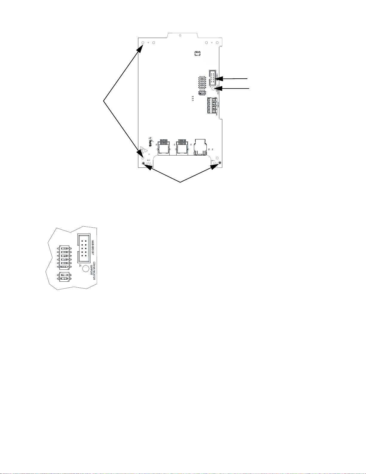
Remove screws and install standoffs
Insert PCB spacer
Plastic pins
Cable
header
Product Installation Document
PN LS10184-000GE-E:B 6/6/2018 18-244
1 Description
The IP/POTS Communicator card transmits system status (alarms, troubles, AC loss, etc.) to a Central Station via the public switched
telephone network and/or Internet protocol. It also allows remote programming or interrogation of the control panel using AlarmNet®.
2 Installation
WARNING: THIS SYSTEM CONTAINS STATIC SENSITIVE COMPONENTS
WEAR A PROPER GROUNDING WRIST STRAP AND WORK ON A STATIC-SAFE WORKSPACE TO PROTECT
ELECTRONIC ASSEMBLIES.
2.1 50 Point and 198 Point Panel Installation
1. Disconnect all power from the fire panel.
2. Remove the two screws at the bottom of the board that are used to attach the board to the chassis.
3. Replace the screws with two 3/4” standoffs from the hardware kit.
4. Insert the plastic PCB spacer into the hole marked “Communicator Support”.
5. Install the 5” cable from the hardware kit into the header on the main PCB marked “Communicator” and the header on the IPOTS-COM
labeled “Main Board Int” as shown below.
6. Holding the IPOTS-COM on an angle, align the pins on the plastic keypad bezel to the hol es on th e sides of the communicator .
7. Lay the IPOTS-COM flat and snap it onto the PCB spacer.
8. Reinstall the screws removed in step 2 into the standoffs at the bottom of the IPOTS-COM.
S
W
2
S
W
3
S
W
1
L
E
D
1
L
E
D
2
L
E
D
3
L
E
D
4
L
E
D
5
L
E
D
6
L
E
D
7
L
E
D
8
J
3
J
5
J
4
E
T
H
L
I
N
E
2
L
I
N
E
1
Align holes onto plastic pins
Cable header
Snap onto PCB spacer
Reinstall screws into standoffs
SW2
SW3
S
W
2
S
W
3
SW2: 6-position dip switch- FUTURE USE- No configuration necessary.
SW3: 2-position dip switch- Factory Settings- Do not change unless instructed to do so by Honeywell.
3 Dip Switches
There are two configurable dip switches on the IPOTS-COM communicator.
2 IPOTS-COM Installation Document — P/N LS10184-000GE-E:B 6/6/2018
 Loading...