

Honeywell IPGSM-DPC User Manual
GSS
IIPPG
CCoommmmeerrcciiaall FFiirree CCoommmmuunniiccaattoorr
IInnssttaallllaattiioonn aanndd SSeettuupp GGuuiidde
IPGSM-DPC Commercial Fire Communicator
M--
M
DPP
D
C
C
e
800-09370 6/11 Rev. A
RADIO TROUBLE
LOW BATT
AC LOSS
AC ON

Contents
General Information .......................................................................................................................1
Package Contents .......................................................................................................................1
Compatible Fire Panels ..............................................................................................................1
Operation .........................................................................................................................................2
Installation ......................................................................................................................................3
ULC Compliance .........................................................................................................................3
STEP 1 – Setup the Customer Account.....................................................................................3
STEP 2 – Register the Communications Module with AlarmNet ...........................................3
STEP 3 – Determine the Signal Strength and Select a Location ............................................4
STEP 4 – Mount and Wire .........................................................................................................4
Wiring the 659EN Line Fault Monitor (if required) ............................................................7
STEP 5 – Program the Communications Module .....................................................................8
STEP 6 – Configure the Fire Panel ...........................................................................................9
STEP 7 – Test the System..........................................................................................................9
Dialer Capture Module Information ............................................................................................10
LED Display Information .............................................................................................................10
PowerBoost1 Module Information................................................................................................11
iGSM Communications Module Information ..............................................................................12
RF Specifications ......................................................................................................................13
Central Station Messages.............................................................................................................13
IPGSM-DPC Trouble Detection Information ..............................................................................14
IPGSM-DPC Specifications ..........................................................................................................14
Wiring Diagram.............................................................................................. Inside of Back Cover

IPGSM-DPC Commercial Fire Communicator – Installation and Setup Guide
General Information
The IPGSM-DPC Commercial Fire Communicator (henceforth referred to as IPGSM-DPC) includes
everything you need to upgrade a commercial fire system that previously reported by POTS to a system that
uses the Internet as its primary reporting path, and uses a GSM cellular reporting path as a backup. In
addition, this communicator utilizes a sophisticated power module (PowerBoost1) that monitors and reports
AC power loss, low battery, and missing battery conditions.
Package Contents
Red Fire Cabinet and Back Plate Antenna and Mounting Adapter Mounting Rails (for above)
Cam Lock with Key PowerBoost1 Hardware Bag
Dialer Capture Module Battery harness/fuse (# 100-02415) Transformer, 18VAC
iGSM Communications Module Ferrite Filter (# 1451-UL9)
50 ohm cable assembly LED Display board
Compatible Fire Panels
The IPGSM-DPC works with:
All Fire Panels that are listed in the table below.
All Fire Panels that use the Contact ID communication format as described in the SIA DC-05
Standard.
IMPORTANT: For a fire panel that has more than 9 active partitions, the first 9 partitions are
reported to the central station uniquely. Beyond 9 partitions, only the 2nd digit of the partition is
reported along with a leading zero (example partition 14 is reported as 04). The installer must
inform the central station of this condition.
The IPGSM-DPC is compatible with the Honeywell brand FACP’s listed below when the model
659EN Line Fault Monitor is installed.
Honeywell Fire Panel Communicator
411 family two
411UD family two
411UDAC family two
FireWarden-100-2C family three
FireWarden-100-2C-FR family three
FireWarden-50C family two
FireWarden-50C-FR family two
MS-10UD-7C family three
MS-10UD-7C-FR family one (requires UDACT)
MS-25C family four
MS-5UD-7C family three
MS-5UD-7C-FR family one (requires UDACT)
MS-9050UDC family two
MS-9050UDC-FR family two
MS-9200UDLSC family three
MS-9200UDLSC-FR family three
MS-9600LSC family three
Use the DACT-UD2 product to
interface the IPGSM-DPC.
Honeywell Fire Panel Communicator
MS-9600LSC-FR family three
Use the DACT-UD2 product to
interface the IPGSM-DPC.
NFS2-3030 family one (requires UDACT)
NFS2-3030-FR family one (requires UDACT)
NFS2-640 family one (requires UDACT)
NFS2-640-FR family one (requires UDACT)
NFS-320 family one (requires UDACT)
NFS-320C family one (requires UDACT)
NFS-320C-FR family one (requires UDACT)
NFS-320SYS family one (requires UDACT)
NFS-320SYS-FR family one (requires UDACT)
NSP-25C family four
SFP-10UDC family three
SFP-10UDC-FR family three
SFP-5UDC family three
SFP-5UDC-FR family three
– 1 –

IPGSM-DPC Commercial Fire Communicator – Installation and Setup Guide
Operation
The IPGSM-DPC replaces the fire panel's POTS communications path. When an event occurs, the fire panel
goes off-hook to dial the central station. The IPGSM-DPC detects the off-hook condition and provides the
fire panel with a dial tone. When the fire panel detects the dial tone, it begins dialing the central station.
The IPGSM-DPC considers the three second period after dialing as the number dialing has been completed.
After the dialing is completed, the Dialer Capture Module returns a handshake to the fire panel.
The fire panel then sends the contact ID reports to the IPGSM-DPC, which in turn sends a kiss-off after the
report is successfully received from the fire panel. Within the IPGSM-DPC, the Dialer Capture Module
sends the contact ID reports over the ECP bus to the iGSM Communications Module. When all the reports
are sent, the fire panel goes on-hook. The IPGSM-DPC then transmits the messages to the central station
(either over the internet or the GSM network).
– 2 –

IPGSM-DPC Commercial Fire Communicator – Installation and Setup Guide
Installation
ULC Compliance
To meet Canadian ULC compliance, ensure the following:
IPGSM-DPC must be installed in accordance with Canadian Electrical Code, Part 1.
IPGSM-DPC must be mounted in the same room and within 20 feet of the fire panel. The wiring
must be routed through conduit.
IPGSM-DPC, and all equipment used for the IP connection (such as the router, hub, modem, etc.)
shall be listed, must be powered from an un-switched branch circuit, and be provided with
appropriate standby power.
IPGSM-DPC must use a 7AH battery (not supplied) to provide 24-hour backup capability.
STEP 1 – Setup the Customer Account
The communicator requires a subscriber account (customer account) to be setup with AlarmNet Direct. This
is accomplished by registering the communicator's iGSM communications module with AlarmNet.
Registering, enables the fire panel to send reports.
To setup the customer account you will need to contact the central monitoring station to get account
information, and have access to the AlarmNet Direct website. To access the AlarmNet Direct website visit –
https://services.alarmnet.com/AlarmNetDirect
If you do not wish to use the AlarmNet Direct website, you may call AlarmNet to setup the account, just
phone 800-222-6525, then select option 1.
(Monday–Friday 8:00 am to 9:00 pm, Saturday 9:00 am to 5:30 pm EST)
Have the following information ready:
Primary City ID (two digits), obtained from your
monitoring station.
Primary Central Station ID (two digits), obtained
from your monitoring station.
Primary Subscriber ID (four digits), obtained
from your monitoring station.
Communication Module's MAC ID, and MAC
CRC number located on outside of box, and
inside of the module.
Note: The SIM supplied for the IPGSM-DPC is already activated. Therefore no SIM
activation is necessary.
STEP 2 – Register the Communications Module with AlarmNet
Registering the module activates the account with AlarmNet and enables the fire system's control panel to
send reports. There are three methods that can be used to register the communications module.
Register the module by logging into AlarmNet Direct and choosing “Show Programmed Devices
GSM/I”. Search for the account using the Account Information or MAC ID. Under the “Actions”
column, use the pulldown menu and choose Register. OR
After the IPGSM-DPC is installed and programmed, you can register the module by clicking the
Tamper Switch 3 times. OR
After the IPGSM-DPC is installed and programmed, you can register the module using the 7720P
Programming tool. Simply: Press [Shift ] then press []. Please wait for "Registration SUCCESS"
message.
– 3 –

IPGSM-DPC Commercial Fire Communicator – Installation and Setup Guide
STEP 3 – Determine the Signal Strength and Select a Location
IMPORTANT - Do Not mount this device outdoors.
RF Exposure
Warning – The antenna(s) used for this transmitter must be installed to provide a separation
distance of at least 20 cm from all persons and must not be collocated or operating in conjunction with any other antenna or transmitter.
When choosing a suitable mounting location, understand that signal strength is very important for proper
operation. For most installations using the supplied antenna, mounting the unit as high as practical, and
avoiding large metal components provides adequate signal strength for proper operation.
In this procedure, you will use the iGSM Communications Module to determine signal strength in order to
find a suitable mounting location.
Note: Since the SIM is already activated, the RSSI signal strength indicators will indicate
signal strength.
1. You will need a fully charged 12V battery.
2. Attach the Antenna (see illustration on page 6).
3. Temporarily wire the battery's negative [–] terminal to TB1–4 on the iGSM communications module,
then wire the battery's plus [+] terminal to TB1–2 on the communications module. Wait about one
minute for the module to initialize.
4. Position the assembly near a suitable mounting position and observe
the RSSI display.
5. Look for a mounting position that yields at least 3 bars lit solid. Four
or five bars are better.
GYGGRY
3 BARS MIN.
7845i-GSM-025-V0
6. Verify the signal strength remains steady for a few minutes, then mark that mounting position.
Disconnect the battery.
STEP 4 – Mount and Wire
For ULC compliant installations, refer to the topic on ULC Compliance in this manual.
For Dry/Indoor use only.
External cabinet wiring MUST be routed in conduit.
This communicator comes partially assembled with all the components mounted except the Antenna, LED
Display board, and PowerBoost1. To protect certain components on the PowerBoost1, it is shipped unmounted but fully wired.
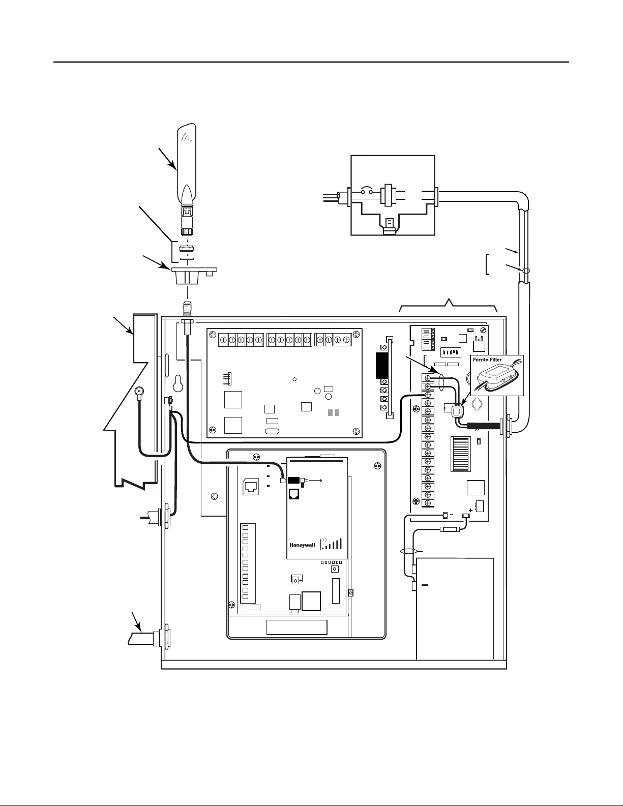
Note: Refer to the diagram on page 6, and to the Wiring Diagram on the inside of the back cover
this manual for wiring and component identification.
1. Remove knockouts from cabinet to accommodate the power input wires, and wiring to the control
panel. (DO NOT REMOVE the two knockouts directly above the PowerBoost1 module.) Then mount
the cabinet securely to the wall using 4 screws or bolts. Use mounting screws or bolts that are
suitable for the material being anchored to.
of
2. Ensure the cabinet door lock is installed.
3. Install the two plastic mounting rails
for the LED Display board. They simply snap into the back
plate holes.
– 4 –
IPGSM-DPC Commercial Fire Communicator – Installation and Setup Guide
4. Connect the LED Display board to its connector, then slide the board into the mounting rails. (Refer
to the “LED Display Information” topic if a wire is detached from its connector.)
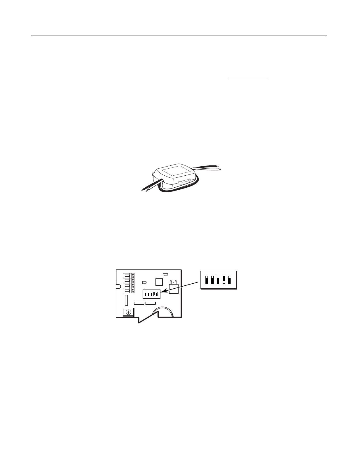
5. Carefully remove the packaging material that surrounds the PowerBoost1.
6. Mount the PowerBoost1 on the three unused standoffs. Use the plastic screw
(prevents shorting)
to secure the upper right corner of the PowerBoost1 and the two metal screws and lock washers to
fasten the left side of the circuit board. Ensure the lock washers are located between the circuit
board and the head of the two metal screws.
7. Use the 1451-UL9 Wired Transformer directly connected to un-switched facility power. Connect and
route 14AWG (minimum) insulated wire from facility ground to the 1451-UL9 enclosure ground post
and through the conduit to the IPGSM-DPC cabinet ground post.
8. Route 16AWG wire from the transformer secondary, through the conduit. Pass the wires through
the Ferrite Filter, then loop the wires back through again making a loop. (Ensure the wire ends that
connect to the PowerBoost1 Module are tinned.) Connect the wires to the PowerBoost1 AC
terminals. At this time DO NOT apply power.
9. Ensure all ground connections are tight.
10. Connect the Ethernet cable and the Telco 1 and Telco 2 lines. If you choose to use an optional
Cabinet Tamper Switch (if the control panel supports it) mount and wire it.
Note: The Ethernet cable, Telco 1, Telco 2 lines, and the optional cabinet Tamper Switch (if used)
must be run through conduit.
11. Verify the PowerBoost1 module DIP switches are configured as shown below.
PowerBoost1
ON
15
2
3
4
iPGSM-COM-008-V0
ON
15
2
3
4
(Switch handle = white)
12. Ensure the following:
LED Display board is fully seated.
All wiring terminals and connectors are tight.
All wiring has been completed and secured with cable ties.
13. Install the battery (not supplied). Apply power to the 1451-UL9 Wired Transformer, and attach the
battery cable.
– 5 –
IPGSM-DPC Commercial Fire Communicator – Installation and Setup Guide
ANTENNA
NUT,
WASHER
ANTENNA
MOUNTING
ADAPTER
CABINET
DOOR
TO 24 HR
FACILITY POWER
120VAC, 60Hz, 850mA
Tip 2
ZN-
Ring 2
ECP
EOL
Telco 1
Telco 2
ZN+
EOL
GND
PWR
Data Out
Dialer Capture Module
Tip 1
Ring 1
GREEN
12V In
Data In
Data Out
RED
1451-UL9 WIRED
TRANSFORMER
WIRES MUST BE
RUN IN CONDUIT
BLU
BLU
GND
POST
18 VAC
72 VA
TO Cabinet Ground Post
TO PowerBoost1
DO NOT REMOVE these knockouts.
ON
15
2
3
GND
Tin wire ends.
4
GND
BLU
BLU
FOR EXTERNAL ANTENNA
50 OHM MMCX ONLY
Power Boost1 Module
BATTERY
FUSE
PN: 100-02415
+
TO Facility
Ground
TB 1
7720P PROGRAMMER PORT
NOT FOR TELEPHONE SERVICE USE!
PRIMARY POWER: 9 - 16.5 VAC
CURRENT: 900mA PEAK, 70mA STANDBY
BATTERY: 8V. 3.1 AHr FOR 24 Hr BACKUP
FCC:XXXXXXXXXX IC: YYYYYYYYYY
1
2
3
4
5
6
7
8
9
10
11
GPRS
RSSI
IBS
M0
M1
CONDUIT
BATTERY
7AH
iGSM Comm Module
(not supplied)
IPGSM-DPC-001-V1
Wiring for Grounds, Power, and RF
– 6 –
 Loading...