

iPCAM-PT2A Pan and Tilt Wireless Internet Video Camera – Quick Installation Guide
For Online Support visit: https://mywebtech.honeywell.com/
General Information
NOTE:
To utilize this camera, you must have:
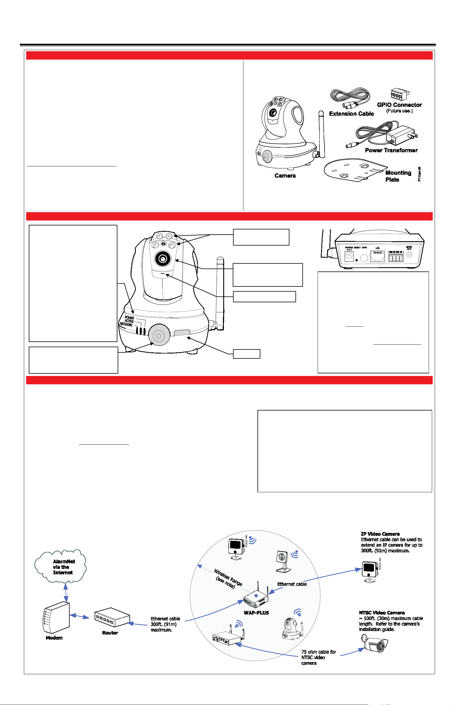
Component Identification
Planning the camera installation
Not used.
Lens – Fixed lens requires
Microphone – Not used.
Power
Active
Network
connected.
Motion Sensor – PIR motion sensor
email notifications.
Power Connector – Connect transformer
Reset Button
WPS Button
LAN Connector
GPIO Connector Socket
Speaker Out
LED Lights – May be
manually activated.
Wireless Range:
Layout Considerations:
and each IP camera for detailed information about that product.
This guide provides information on installing and setting up Honeywell's iPCAM-PT2A
Camera. This camera is ideal for monitoring your home, business or public facilities.
With the addition of the Auto-Calibration Correction feature, IPCAM-PT2A DOES
NOT spin on its pedestal upon software reset. The camera spins only upon power-up or a
manual Pan/Tilt command.
Camera features include:
• Wired or Wireless communications to a router or access point. Wireless communications
utilizes the 802.11b/g/n protocol with WPS security. WPS (Wi-Fi Protected Setup) is a
standard for easy setup of a secure wireless network.
• Pan and Tilt Color video can be controlled and monitored through your Total Connect
remote services account. Up to 6 cameras can be used.
• Auxiliary LED lighting that improves the quality of video up to 15 feet (4.5m) in low-level
light situations.
IMPORTANT: This camera is for indoor use only. To avoid damage to the drive mechanism,
do not manually pan or tilt the camera. DO NOT mount this camera within 1 foot (0.3m) of
any wireless device.
• An AlarmNet account for a cellular or Internet communicator, or a “Video Services Only”
account.
• Total Connect account. (If an account does not exist, the dealer should use the AlarmNet
website to set up a Total Connect account for the customer.)
• Internet access with a router capable of DHCP hosting. For wireless, the router must also
support one button WPS data encryption. If this is not available, order the Honeywell
WAP-PLUS Wireless Access Point for connection to your router.
PACKAGE CONTENTS
• Blinking Green – Camera
initialization period, allow up to 2
minutes.
• Steady Green – Camera is
initialized and power is on.
• Off – No user is monitoring the
camera.
• Blinking Green – User(s) are
monitoring the camera.
• Steady Green – Wireless / LAN is
available.
• Blinking Green – Network transfers.
• Blinking Amber – Indicates a WPS
configuration is in process.
• Steady Amber – WPS fault.
• Off – Wireless / LAN not
used to trigger programmed events,
such as capturing video and sending
A camera installation can be as simple as installing one camera, or up to six cameras per
Total Connect account. In large installations it may include a mix of wireless, and wired cameras.
The installer should work closely with the customer to achieve a satisfactory installation.
no focusing. Clean with a
soft tissue and lens cleaner.
here.
settings. (Use a paper clip to depress and
hold for 12 seconds, then RELEASE.)
Upon a successful reset, the Power, Active,
and Network LEDs blink 3 times.
configure wireless encrypted connectivity.
connectivity. When connected, wireless is
disabled. The camera must be powered off
whenever connecting or disconnecting the
Ethernet cable.
– Resets IP Camera to default
– Used during setup to
– Used for wired
– Future use.
– Not used.
• Depending on layout and distances, one or more WAP-PLUS units may be
needed.
• Wireless distance may be reduced by thick walls, wire lath, and large metal
objects.
• When setting up a wireless configuration in very large buildings or buildings with
dense walls, wireless communications may be marginal. It is best to first
configure the system’s wireless security in the same room (within 20 feet, 6m).
Upon successful configuration, place each camera in the desired location, and
verify in Total Connect that everything works.
• For installations where multiple WAP-PLUS units are used, label the units to
indicate which IP cameras are linked to which WAP-PLUS.
• Each IP camera or ACU (Analog Converter Unit) will communicate through its
associated WAP-PLUS.
• Each WAP-PLUS must be spaced at least 4 feet (1.2m) from other wireless
devices.
• Ensure each device uses the correct power transformer. When needed, secure
wires with cable ties.
• Refer to the installation guides for the WAP-PLUS, ACU (Analog Converter Unit),
The wireless range and bandwidth (data rate) are dependent on the
wireless technology used; as determined by the 802.11b/g/n
specifications. This determines the range and data transfer rate. For
instance under ideal conditions,
802.11 g provides up to 125 ft. (38m) range, and 54Mbits/s data rate, and
802.11 n provides up to 230 ft. (70m) range, and 150Mbits/s data rate.
Other factors that reduce the range are thick walls, wire lath, large metal
objects, and the number of cameras sending data.
Because of the many variables, the best way to determine if the
installation is successful, is to test the finished installation by logging into
the Total Connect website and checking each camera.
1. Mount the camera
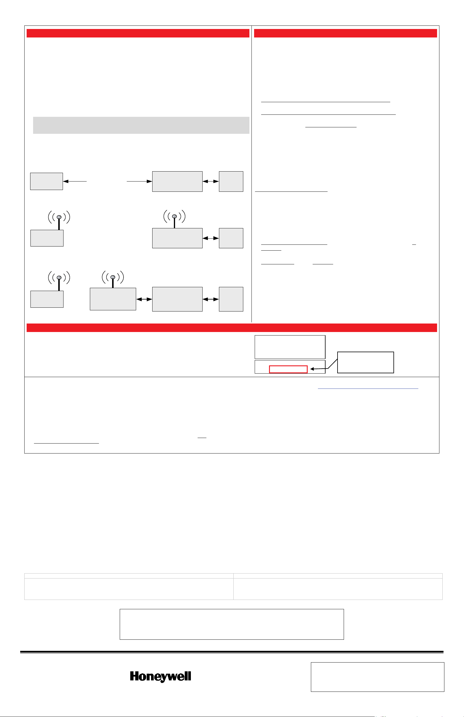
2. Power and configure wireless security
For wireless connections
Power and configure wireless security
mounting plate
power transformer
power connector
DO NOT PLUG IN THE POWER TRANSFORMER AT THIS TIME.
NON-SWITCHABLE
Configuration #3 - Your wireless Router supports DHCP but DOES NOT support one
button WPS encryption.
IP Camera
Router
• DHCP capability.
Modem
Configuration #2 - Your wireless Router supports DHCP and one button WPS encryption.
IP Camera
Router (wireless)
• DHCP capability.
• WPS button.
Modem
Configuration #1 - You are using a wired connection and your Router supports DHCP.
IP Camera
Router
• DHCP capability.
Modem
Wireless Access
Point
• WPS Button
Ethernet Cable
Configuration #1:
Configuration #2
Configuration #3
Configuring Wireless Security:
3
seconds
1 minute
NOTE:
wireless modes
3. Enroll camera(s) or modify settings in AlarmNet
Model
No:
Serial
No:
MAC:
IIIIIIIIIIIIIIIIIIIIIIIIIIIIIIIIIIIIIIIIIIIIIIII
000E
8
F79
C
7C
3
iPCAM-
PT
2A
IIIIIIIIIIIIIIIIIIIIIIIIIIIIIIIIIIIIIIIIII
090318
YL50000015
http://www.alarmnet360.com/
Help
Customers without AlarmNet accounts:
Customers with an existing “Video Only” account:
Customers with an existing AlarmNet cellular or Internet communicator
account
https://rs.alarmnet.com/totalconnect2#/
The cameras are now ready for customer use.
FEDERAL COMMUNICATIONS COMMISSION STATEMENTS
CLASS B DIGITAL DEVICE STATEMENT
• If using an indoor antenna, have a quality outdoor antenna installed.
• Move the antenna leads away from any wire runs to the receiver/control.
• Plug the receiver/control into a different outlet so that it and the radio or television receiver are on different
branch circuits.
• Move the radio or television receiver away from the receiver/control.
• Consult the dealer or an experienced radio/TV technician for help.
INDUSTRY CANADA CLASS B STATEMENT
FCC / IC STATEMENT
indésirable.
DECLARACIÓN COFETEL
DECLARACIÓN ANATEL
La operación de este equipo está sujeta a las siguientes dos condiciones.
Este equipamento opera em caráter secundário, isto é, não tem direito a proteção contra
TRADEMARKS
2 Corporate Center Drive, Suite 100
P.O. Box 9040, Melville, NY 11747
WARRANTY
The MAC ID is on the
the carton.
: Wireless security should be configured before permanently
mounting the cameras (refer to #2,
On horizontal surfaces such as a shelf, the
typically is not needed. However if
at right).
there is vibration, or the mounting surface is very small you may wish to use the mounting
plate. This will ensure that the camera is not disturbed by vibration or the wires being tugged.
1. If mounting to a vertical or overhead surface, use the mounting plate. Use all three holes in the
mounting plate with screws that are suitable for the surface; do not use flat-head screws.
2. Slide the camera onto the mounting plate until fully seated as indicated by a clicking sound.
3. Orient the antenna vertically.
4. Connect the
’s wire to the
on the back of the camera.
IMPORTANT: If you need a longer power transformer cable (6 ft., 1.8m), you can order the
iPCAM-EXT extension cable. This will add 9 feet (2.7 meters) to the supplied transformer for
a total of 15 feet (4.5 meters). You may use ONLY one power extension cable.
NOTE: THE TRANSFORMER MUST BE POWERED BY A
OUTLET.
5. Refer to the diagram below, and determine which configuration applies.
Refer to the configuration illustrations, below left.
Connect each camera to the router with an Ethernet cable.
Then plug the Power Transformer into an outlet. Camera installation is DONE.
: Complete all the steps below.
: Connect the optional Honeywell WAP-PLUS Wireless
Access Point to the router, then complete the steps below.
NOTES:
• In order for the camera to be configured in wired mode, the Ethernet cable
must be connected first, then apply power.
• In order for the camera to be configured in wireless mode, make sure NO
Ethernet cable is connected. Apply power.
• When setting up a wireless configuration in very large buildings or
buildings with dense walls, wireless communications may be marginal. It is
best to first configure the system in the same room. Then upon successful
configuration, place each camera in the desired location.
• If using more than one wireless camera, each must be configured for
wireless security. Configure one camera at a time.
• If using a router instead of Honeywell's WAP-PLUS, ensure that the router
is configured for DHCP. (This is the default setting for most routers.) If
you are unsure, access the router's configuration settings and enable
DHCP (refer to the router's manual).
Each IP camera or ACU must be configured separately. Follow these steps:
1. Ensure the WAP-PLUS is on and fully booted (allow 2 minutes for the boot
process to complete).
2. Ensure an Ethernet cable is NOT connected to the IP camera. Then plug
the IP camera’s Power Transformer into an outlet. Ensure the camera is
powered up and fully booted (allow 2 minutes for the boot process to
complete).
3. At the Router or WAP-PLUS, press and hold the WPS button for
, then RELEASE. The WAP-PLUS Security light starts blinking.
Other wireless access points may operate differently.
4. At the camera, within
, click and RELEASE the WPS button.
5. The indicator LED will blink amber during the WPS process, then turn
green. Allow up to 45 seconds for the WPS process to complete.
6. Repeat the steps above for each camera.
You will need the following information:
• MAC ID for each camera. The MAC ID is on the camera bottom and the carton.
• AlarmNet account with user name and password.
If you do not have the AlarmNet account number, you may use the MAC ID of your
communicator or alarm panel.
Dealers can enroll cameras and set up Total Connect accounts for customers
by visiting the AlarmNet website at
Click
at the bottom of the page. Refer to PDF of the Online Help
Guide for these topics:
•
See “Accounts ► Account Generation”.
•
Devices” to add a new camera.
•
Remote Service Capabilities icon is present. Then add the new camera.
The user shall not make any changes or modifications to the equipment unless authorized by the Installation Instructions or User's Manual. Unauthorized changes or modifications could void the user's
authority to operate the equipment.
This equipment has been tested to FCC requirements and has been found acceptable for use. The FCC requires the following statement for your information:
This equipment generates and uses radio frequency energy and if not installed and used properly, that is, in strict accordance with the manufacturer's instructions, may cause interference to radio and
television reception. It has been type tested and found to comply with the limits for a Class B computing device in accordance with the specifications in Part 15 of FCC Rules, which are designed to provide
reasonable protection against such interference in a residential installation. However, there is no guarantee that interference will not occur in a particular installation. If this equipment does cause interference
to radio or television reception, which can be determined by turning the equipment off and on, the user is encouraged to try to correct the interference by one or more of the following measures:
: Make sure the account number is green (registered) and the Has
button on the back of the camera to restore factory defaults:
• Delete the camera from the AlarmNet account
• Re-enroll it in the account
• Reconfigure wireless security for the camera
When the camera is set up and the customer’s Total Connect account is established,
.
they can view their video by visiting:
• Have the customer log into their Total Connect account to view the video.
See “Adding IP Video
• The customer may be prompted to install or update QuickTime® and/or Flash® Player.
• If any cameras are mounted upside down, there is a setting to flip the image upright.
• At this time the location of each camera can be adjusted for the desired view.
• When adding, editing, or deleting a camera, the customer can receive email
notification.
• For more camera information, see the Total Connect Online Help Guide.
In
, these steps are required if you use the Reset
camera bottom and
• Reorient the receiving antenna until interference is reduced or eliminated.
This Class B digital apparatus complies with Canadian ICES-003.
Cet appareil numérique de la classe B est conforme à la norme NMB-003 du
Canada.
1. Es posible que este equipo o dispositivo no cause interferencia perjudicial y.
2. Este equipo debe aceptar cualquier interferencia, incluyendo la que pueda causar su operación
no deseada.
Honeywell is a registered trademark of Honeywell International Inc.
Flash is a registered trademark of Adobe Systems Incorporated, registered in the U.S. and other countries.
QuickTime is a registered trademark of Apple Inc., registered in the U.S. and other countries.
Ê800-224187Š
800-22418 6/16 Rev. A
This device complies with Part 15 of the FCC Rules, and RSS210 of Industry Canada. Operation is subject to the
following two conditions: (1) This device may not cause harmful interference, and (2) This device must accept any
interference received, including interference that may cause undesired operation.
Cet appareil est conforme à la partie 15 des règles de la FCC & de RSS 210 des Industries Canada. Son
fonctionnement est soumis aux conditions suivantes: (1) Cet appareil ne doit pas causer d' interferences nuisibles.
(2) Cet appareil doit accepter toute interference reçue y compris les interferences causant une reception
Copyright 2016 Honeywell International Inc.
www.honeywell.com/security
interferência prejudicial, mesmo de estações do mesmo tipo, e não pode causar interferência a
sistemas operando em caráter primário.
For the latest warranty information go to:
http://www.security.honeywell.com/hsc/resources/wa/
 Loading...