

Honeywell IPC5000 Installation Manual

IPC5000
Universal Programmable
Controller
Installation Manual
57-77-25-19

Notice
Copyright 2007 by Honeywell
Revision 1.29
June 2007
Warranty / Remedy
Honeywell warrants goods of its manufacture as being free of defective materials and faulty workmanship.
Contact your local sales office for warrenty information. If warranted goods are returned to Honeywell during
the period of coverage, Honeywell will repair or replace without charge those items it finds defective. The
foregoing is Buyer’s sole remedy and is in lieu of all other warranties, expressed or implied, including
those of merchantability and fitness for a particular purpose. Specifications may be changed without
notice. The information we supply is believed to be accurate and reliable as of this printing. However, we
assume no responsibility for its use.
While we provide application assistance personally, through our literature and the Honeywell web site, it is up
to the customer to determine the suitability of the product in their application.
Industrial Measurement and Control
Honeywell Pte LTD
Honeywell Building
17 Changi Business Park Cetral 1
Singapore

To the Users
Warning
1. Keep the manual with the programmer so that a user can operate it properly.
2. Handle this product only after you have carefully read and understand the installation manual.
3. Honeywell does not bear responsibility for any damage inflicted by careless use of the product.
4. This manual cannot be duplicated, re-edited or transferred in any form fully or partially without a
prior consent from Honeywell. The content of this manual can be modified without prior notice.
5. Please contact Honeywell if you have any questions or queries regarding this manual.
Thank you for purchasing IPC5000 (Universal Programmable Controller).
This manual describes how to install and use IPC5000. To optimize the
control solutions for furnaces, environmental chambers, ovens, reactors,
cookers, freeze dryers, extruders, and other processes with similar control
re
q
uirements, please read this manual carefully.
●
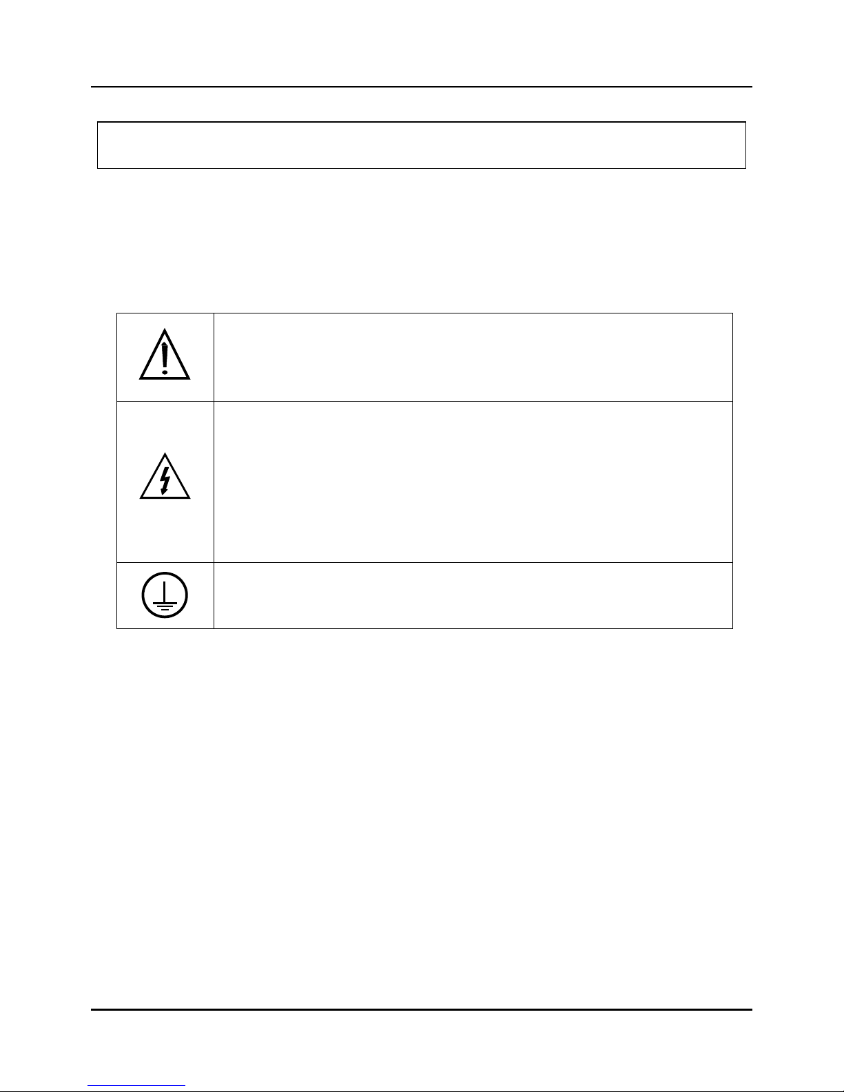
Explanation of symbols used
Pictures and rules described below indicate potential danger that can injure the user or the product.
Before reading the main text of the manual, please become familiar with the following symbols that
indicate various degrees of damage.
●
Examples of symbols
This CAUTION symbol on the equipment refers the user to the product manual for
additional information. This symbol appears next to required information in the
manual.
WARNING
PERSONAL INJURY: Risk of electrical shock. This symbol warns the user of a
potential shock hazard where HAZARDOUS LIVE voltages greater than 30 Vrms,
42.4 Vpeak, or 60 Vdc may be accessible.
Failure to comply with these instructions could result in death or serious
injury.
Protective Earth (PE) terminal. Provided for connection of the protective earth
(green or green/yellow) supply system conductor.
Safety Points
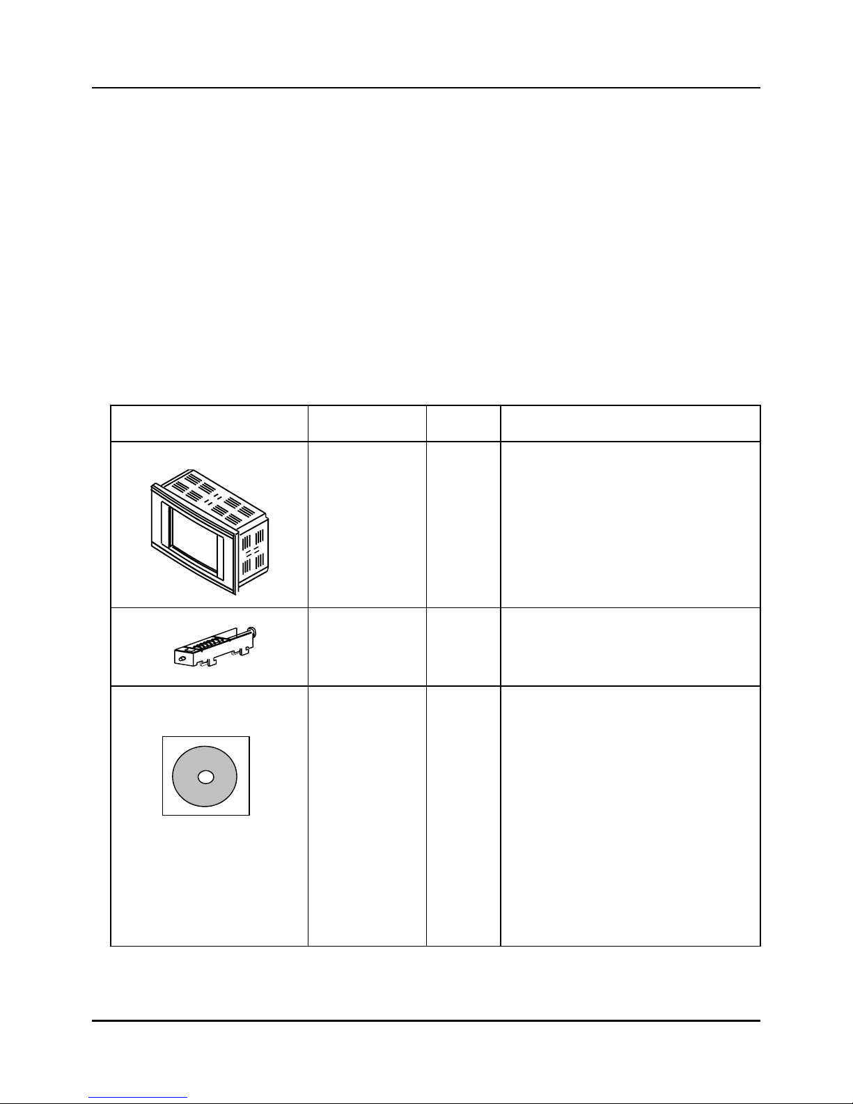
Points to check when unpacking the product:
The IPC5000 consists of the following items.
Please, check the following items when unpacking the product:
1. Verify the model number is correct;
2. Whether the product has been damaged;
3. Whether the container includes all the ordered items.
Points to check when installing the product:
If any of the following components are missing or if the product is damaged after you
unpack it, contact Honeywell.
Name Model number Quantity Remarks
Main frame
IPC5000 1
Refer to the Section 5(Model Number
Interpretation)
Installation bracket
10-03057
4
CD for installation
1
PC Software(Setup program)
PC Software User Manual(English)
PC Software Install Manual(English)
PC Software User Manual(Korean)
PC Software Install Manual(Korean)
IPC5000 User Manual(English)
IPC5000 Install Manual(English)
IPC5000 User Manual(Korean)
IPC5000 Install Manual(Korean)
IPC5000 Communication Manual(English)
IPC5000 Communication Manual(Korean)

Contents
1. Overview............................................................................................................ 1
1.1 Introduction....................................................................................................................................1
1.2 Feature Summary...........................................................................................................................1
2. Installation and wiring......................................................................................2
2.1 Installation environment................................................................................................................2
2.2 Installation precautions.................................................................................................................3
2.3 Panel cutout dimension ................................................................................................................4
2.4 Installation of fixed brackets.........................................................................................................6
2.5 Making Terminal Connections......................................................................................................8
2.6 Terminal Array................................................................................................................................9
2.7 Wiring............................................................................................................................................10
2.7 Terminal Allocation......................................................................................................................25
2.8 Rear terminal................................................................................................................................26
3. Configuration..................................................................................................27
3.1 Screen configuration...................................................................................................................27
3.2 Configuration screen...................................................................................................................28
3.3 AI SET screen...............................................................................................................................29
3.4 PWM set Screen...........................................................................................................................35
3.5 AO SET screen.............................................................................................................................37
3.6 DIO status screen.........................................................................................................................40
3.7 RANGE SET screen .....................................................................................................................45
3.8 OFFSET screen ............................................................................................................................47
3.9 Compensation set screen ...........................................................................................................48
3.10 EVENT SET.................................................................................................................................50
3.11 MODE Event set screen.............................................................................................................53
3.12 ALARM EVENT SET screen.......................................................................................................56
3.13 CONTROL SET screen...............................................................................................................60
3.14 PID ZONE SET screen ...............................................................................................................63
3.15 PID CONSTANT SET screen......................................................................................................67
3.16 PID set screen ............................................................................................................................69
3.17 SYSTEM SET screen..................................................................................................................71
3.18 TROUBLE SET Screen...............................................................................................................75
3.19 TROUBLE MESSAGE set...........................................................................................................78

3.20 NETWORK SET Screen..............................................................................................................79
3.21 INITIALIZE screen ......................................................................................................................80
4. Specification ................................................................................................... 82
5. Model Number Interpretation.........................................................................90

Tables
Table 2.7.1 Minimum Recommended Wire Sizes········································································ 10
Table 2.7.2 Instrument input range code and range ···································································· 21
Table 2.7.3 The function table of External switch input (Digital input) ········································· 23
Table 3.6.1 Defaults of compensation ·························································································48
Table 3.11.1 Mode Event information ·························································································· 53
Table 3.11.2 DO information assigned by REGISTRATION number ··········································· 55
Table 3.12.1 Alarm Event Flowchart····························································································58
Table 3.12.2 Alarm Event On/Off Operation Algorithm ································································59
Table 3.21.1 Initial PID parameter list··························································································81

Figures
Fig. 2.3.1 Panel cutout···················································································································4
Fig. 2.4.1 Installation of fixed brackets ··························································································6
Fig. 2.5.1 Terminal with tube·········································································································· 8
Fig. 2.5.2 Terminal diagram label and Terminal Block style···························································9
Fig. 2.6.1 Mains Power Supply···································································································· 11
Fig. 2.6.2 Analog input 1 / input 2 Connections··········································································· 12
Fig. 2.6.3 Control output 1 / output 2 Connections······································································ 13
Fig. 2.6.4 Digital outputs Connection···························································································14
Fig. 2.6.5 Digital inputs Connections···························································································15
Fig. 2.6.6 Auxiliary output 3 output 4 Connections ······································································16
Fig. 2.6.7 RS-232C communication 9 pin Connection································································· 16
Fig. 2.6.8 RS-232C communication 25 to 9 pin Connection························································ 17
Fig. 2.6.9 RS422/485/Modbus Communications Option Connections (3-Wire shield) ················ 18
Fig. 2.6.10 RS422/485/Modbus Communications Option Connections (5-Wire shield) ·············· 19
Fig. 2.8.1 Rear Terminal ··············································································································26
Fig. 3.1.1 Screen switch block····································································································· 27
Fig. 3.1.2 Main menu screen·······································································································28
Fig. 3.2.1 SETUP (Configuration)································································································28
Fig. 3.3.1 AI SET Screen ·············································································································29
Fig. 3.3.2 SENSOR TYPE SELECTS·························································································· 29
Fig. 3.4.1.a Outputs Assigning block diagram-IPC5000D ··························································· 33
Fig. 3.4.1.b Outputs Assigning block diagram-IPC5000S····························································34
Fig. 3.4.2 PWM SET screen-IPC5000S ······················································································35
Fig 3.4.4 Pulse control output at MV = 75% ················································································ 36
Fig. 3.5.1 AO SET screen ············································································································ 37
Fig. 3.5.2 Combo box for selecting anlog output source ·····························································39
Fig. 3.5.3 Current output scale adjustable graph········································································· 39
Fig. 3.6.1 DI/DO Screen ··············································································································40
Fig. 3.6.2 Digital outputs ON/OFF status····················································································· 43
Fig. 3.6.3 Digital output type selection·························································································43
Fig. 3.6.4 DO TYPE SET screen································································································· 44
Fig. 3.6.5 Arranging PWM No. of Digital output···········································································44
Fig. 3.7.1 RANGE SET screen····································································································45
Fig. 3.8.1 OFFSET screen···········································································································47
Fig. 3.9.1 Compensate set screen·······························································································48

Fig. 3.10.1 The part to arrange events to digital outputs on FIX SET screen of User Manual·····51
Fig. 3.10.2 The part to arrange PV and Time events to digital outputs on SEG EDIT screen
of User Manual ··········································································································52
Fig. 3.11.1 MODE EVENT SET ··································································································· 53
Fig. 3.12.1 ALARM SET screen···································································································56
Fig. 3.13.1 CONTROL SET screen ·····························································································60
Fig. 3.13.2 PID ZONE Set screen ·······························································································61
Fig. 3.13.3 Example for setting Segment PID group ···································································62
Fig. 3.14.1 PID ZONE SET screen······························································································63
Fig. 3.15.1 PID Const set ············································································································67
Fig. 3.16.1 PID SET screen·········································································································69
Fig. 3.17.1 SYSTEM SET screen································································································ 71
Fig. 3.17.2 Fix Control Operation when SP Tracking On and JC = 2 ··········································72
Fig. 3.17.3 Fix Control Operation when SP Tracking Off and JC = 2 ··········································72
Fig. 3.18.1 Trouble and Tune Lock Setting Screen ·····································································75
Fig. 3.18.2 Trouble Message Window························································································· 76
Fig. 3.18.3 Trouble Message List ································································································76
Fig. 3.18.4 MON SUB Screen ·····································································································77
Fig. 3.19.1 Assigning the TROUBLE MESSAGE ········································································78
Fig. 3.19.2 Keypad Switching······································································································78
Fig. 3.20.1 Network Setting Screen·····························································································79
Fig. 3.21.1 INITIAL screen···········································································································80
Fig. 3.21.2 Confirm for initializing ································································································80

- 1 -
1. Overview
1.1 Introduction
The IPC5000 is a universal programmable microprocessor-based, a single loop or two-loop
controller. It has a typical accuracy of ± 0.10 % of span, two analog control loops, 12 digital
inputs and outputs, 100 programs and 2000 segments. The IPC5000 is an ideal control
solution for furnaces, dryers and environmental chambers, corrosion testing chambers, lab
ovens, sterilizers and other processes with similar control requirements.
1.2 Feature Summary
z IPC5000D support two mode; Synchronous and Asynchronous mode
- Synchronous: depending on TIME each loop
- Asynchronous mode: independent on time each loop
z 1 or Up to 2 loops, including:
- Proportional Integral Derivative (PID),
- ON/OFF and,
- Heating/Cooling control
z Auto tuning for each control loop and automatic tuning for all zones (Max. 8 zones).
z Up to 36 different selection for 2 analog inputs
z 2 universal control output (Voltage pulse, Current (4~20mA), Relay)
z 12 digital inputs and 12 digital outputs
z Up to 100 programs, total 2000 segments
z Easy operator interface by touch screen and graphic displays by LCD.
z Universal Power(100 to 240 VAC) or 37 VA
z Ethernet communication (Option)
z Y2K compliant
<IPC5000S>
z Up to 36 selection for 1 analog input
- 2 -
2. Installation and wiring
2.1 Installation environment
Panel mounted, indoor Process Control Equipment; Pollution degree 2, Installation Category II
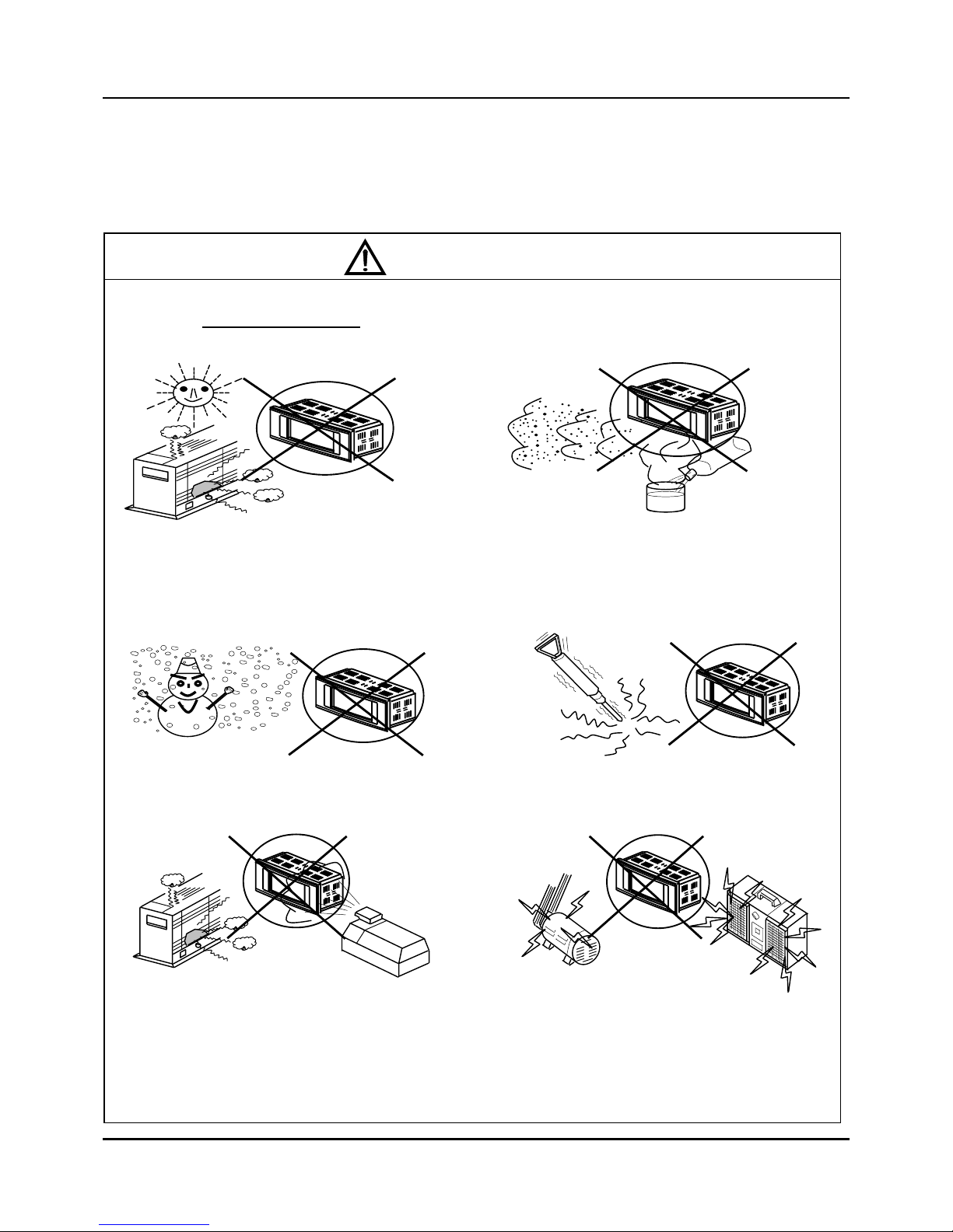
Warning
In order to enhance the product’s credibility and give full scope to IPC5000 functions, do not install
the product in the following places
.
z Place where temperature exceed
50°C(122°F)
z Place exposed to direct sunlight
z Outdoors
z Places exposed to corrosive or flammable
gases
z Place with dust, salinity, iron powder and other
conductible substandes and organic solvents
z Places with a sub-zero temperature
(below 0℃)
z Places susceptible to vibration and shock
z Places with humidity of over 85%
z Places with abrupt temperature changes that
cause dewdrops
z Place exposed to water, oil or chemical substances
z Places exposed to strong electronmagnetic fields
- 3 -
2.2 Installation precautions
This section describes precautions that should be taken when installing IPC5000
(Universal Programmable controller). It is essential to consider environmental stress,
cracking resistance and operability.
1) Provide sufficient space for ventilation.
2) Do not install right above devices inside the panel that generate excessive heat such as
(transformers, large-capacity resistors).
3) Install far from high-voltage devices, power devices or their cables, or install in a separate
panel.
4) Use exclusive grounding to deal with noise. If the grounding cable is long enough to reach
the grounding point, use a thick insulated wire and ground to earth ground.
5) Do not bind communications or data cables of IPC5000 with the cables of power devices or
other cables that cause noise. When wiring in an identical duct, connect a shield cable to the
FG terminal of the main frame.
6) Select a flat installation panel with no curves
7) If you want to use the product after having kept it in temperatures below 0 ℃, allow it to
warm up for at least 30 minutes at room temperature by connecting the power supply.
Otherwise, there is a risk of damaging the product.
8) Before you clean the IPC5000, disconnect the IPC5000 from the site AC source. Clean your
IPC5000 with a soft cloth dampened with water. Do not use liquid or aerosol cleaners, which
may contain flammable substances.
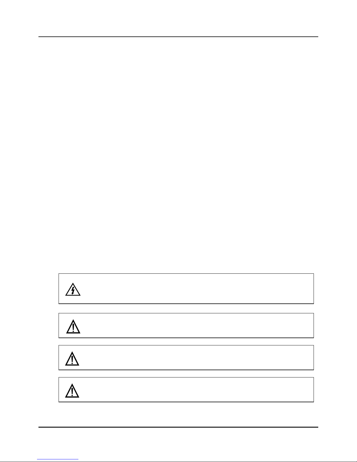
WARNING
Be sure to turn off the main power supply when you are installing or removing the
controller. Failure to heed this warning may lead to electric shock.
Be sure to follow the operating requirements (regarding temperature, humidity, voltage,
vibration, shock, mounting direction etc.) as stated in the specifications of the controller.
Make sure that wire scraps, chips or water do not enter inside the case of the controller.
Failure to heed this caution may lead to fire or malfunction.
Do not block the ventilation openings.
Failure to heed this caution may lead to fire or malfunction.

- 4 -
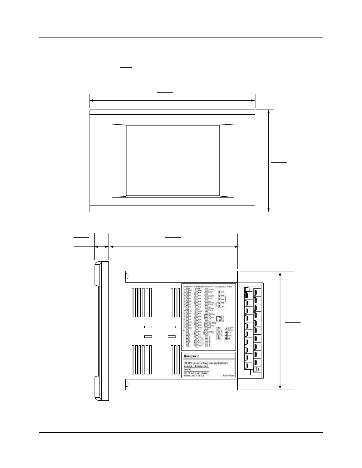
2.3 Panel cutout dimension
Use 2mm thick steel panels in setting up the IPC5000.
Fig. 2.3.1 Panel cutout
02.
0
5.0
303.7
5.185
±
±
02.
0
5.0
744.
4
5.120
±
±
(Unit:
inch
mm
)
Install the IPC5000 in a location where the lower panel is not exposed to temperatures
that exceed the operating temperature range (0 to 50 ˚C).
Make sure that the temperatures above and below the controller meet specified
requirements.
- 5 -
z Dimensions (Unit:
inch
mm
)
717.7
0.196
157.5
0.131
539.5
7.140
512.0
0.13
685.4
0.119

- 6 -
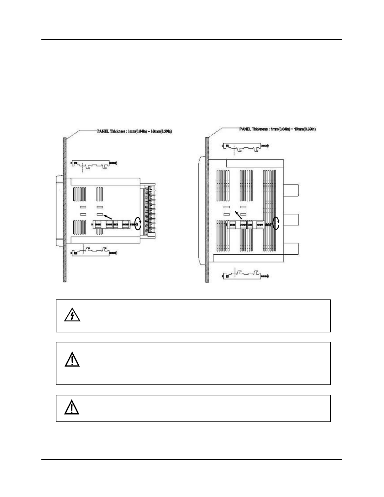
2.4 Installation of fixed brackets
Fig. 2.4.1 Installation of fixed brackets
Top
Right
Left
Bottom
Hole for installing fixed brackets
- 7 -
Mounting Method
Before mounting the controller, refer to the nameplate on the inside of the case and make a note of the
model number. It will help later when selecting the proper wiring configuration.
Remove the mounting kit from the shipping container, and install the kit as follows:
z Insert the prongs of the fixed bracket into the holes
z Tighten the screw to secure the case against the panel
Torque for clamping screws is 3~5 kg-cm (28 ~ 49 N-cm, 42~ 70 oz-in)
You may install the two brackets to the right or to the left, or at the top and the bottom.
* The case must be installed with 4 fixed brackets in case IP65 level is required for the
front protection. (Two for the top and bottom, and two for both right and left sides)
WARNING
Make sure that the main power is switche d off before mounting IPC5000. Otherwise,
there is a risk of electrical shock.
Side View
Top View
- 8 -
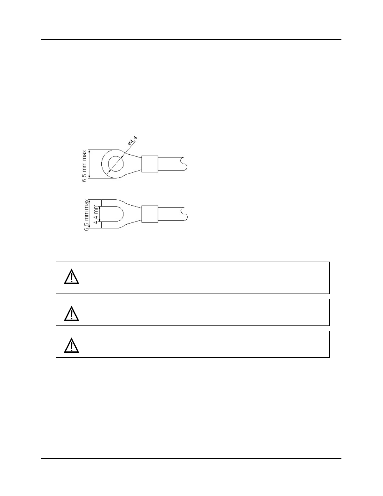
2.5 Making Terminal Connections
To connect a line to the terminals (Power or Signals), use crimp-style solderless wire connectors
that fit an M3.5 screw.
z Wire No. : #14 AWG (2.1 mm
2
)
Fig. 2.5.1 Terminal with tube
If the IPC5000 is mounted in a location subject to noticeable vibration or impact, be sure
to use round crimp-style solderless wire connectors to prevent lines from becoming
disconnected from the terminals.
The terminal screws shall be tightened to 12 lb-in (5 kg-cm, 49 N-cm) torque.
Be careful not to allow any of the crimp-style solderless wire connectors to touch
adjacent terminals or connectors.
- 9 -
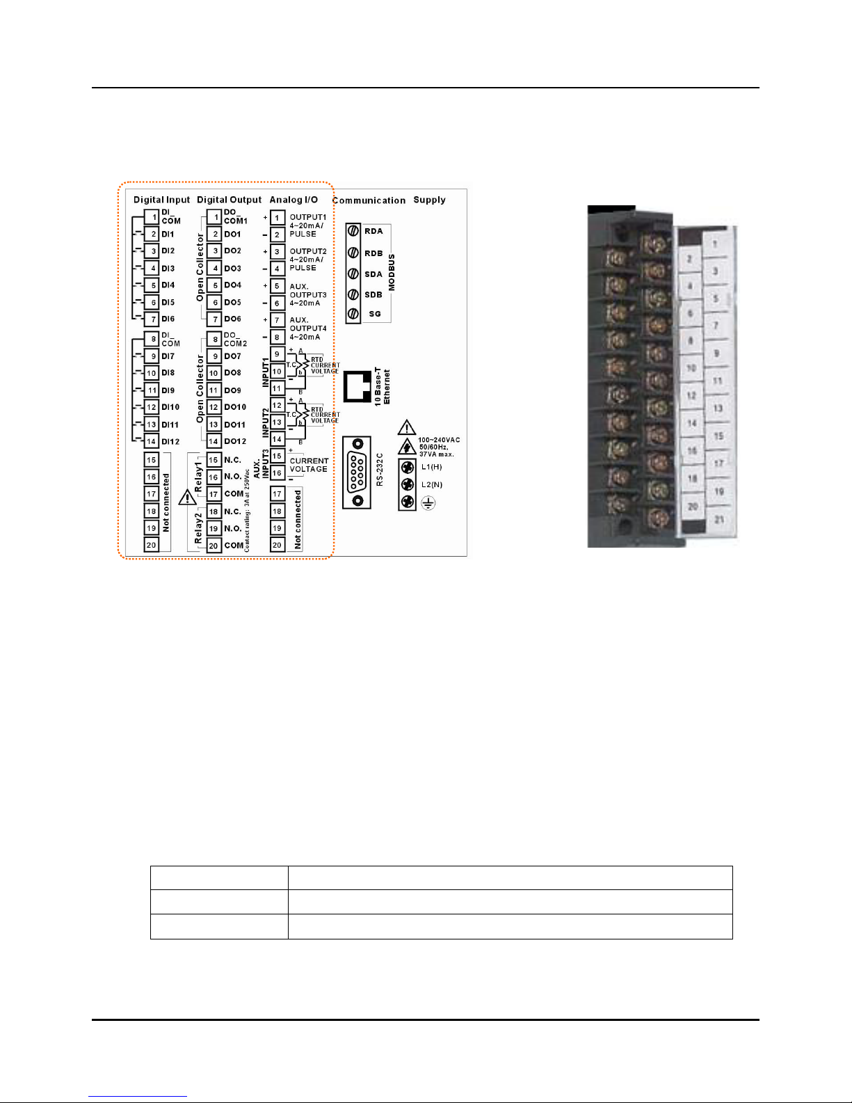
2.6 Terminal Array
Wries are connected to the terminal base according to the layout , shown at left in Fig 2.5.2
Fig. 2.5.2 Terminal diagram label and Terminal Block style
Terminal Block Style
The terminal block is available in the barrier style, shown at right in Fig.2.5.2.
z Screw : M3.0
z Wire No. : #22 to 16AWG
Wiring Rules and Recommendations
In general, stranded copper wire should be used for non-thermocouple electrical connections.
Twisted-pair wiring with shielded cable will improve noise immunity if wire routing is suspect.
Wire Gage
The recommended minimum wire size for connections is as follows.
Wire Gauge Wire Application
20 DC current and voltage field wiring
22 DC current and voltage wiring in control room

- 10 -
2.7 Wiring
Line voltage wiring
The controller is considered “rack and panel mounted equipment” per EN61010-1, Safety
Requirements for Electrical Equipment for Measurement, Control, and Laboratory Use, Part 1:
General Requirements. Conformity with 72/23/EEC, the Low Voltage Directive requires the user to
provide adequate protection against a shock hazard, the user shall install this controller in an
enclosure that limits OPERATOR access to the rear terminals.
Controller Grounding
PROTECTIVE BONDING (grounding) of this controller and the enclosure in which it is installed
shall be in accordance with National and local electrical codes. To minimize electrical noise and
transients that may adversely affect the system, supplementary bonding of the controller enclosure
to a local ground, using a No.12(4 mm
2
) copper conductor, is recommended.
Control/Alarm Circuit Wiring
The insullation of wires connected to the Control/Alarm terminals shall be rated for the highest
voltage involved. Extra Low Voltage (ELV) wiring (input, current output, and low voltage
Control/Alarm circuits) shall be separated from HAZARDOUS LIVE (>30 Vac, 42.4 Vpeak, or 60
Vdc) wiring.
Terminal Block Style
The terminal block is available in the barrier style, shown in Fig.2.6.1.
z Screw : M3.5
z Wire No. : #16 to 14AWG
Wiring Rules and Recommendations
In general, stranded copper wire should be used for non-thermocouple electrical connections.
Twisted-pair wiring with shielded cable will improve noise immunity if wire routing is suspect.
Wire Gage
Observe all local codes when making power connections. Unless local electrical codes
dictate other wire, the recommended minimum wire size for connections is given in Table
2.7.1.
Table 2.7.1 Minimum Recommended Wire Sizes
Wire Gauge Wire Application
14 to 16 AC to power supply
10 to 14 Earth ground wire
- 11 -
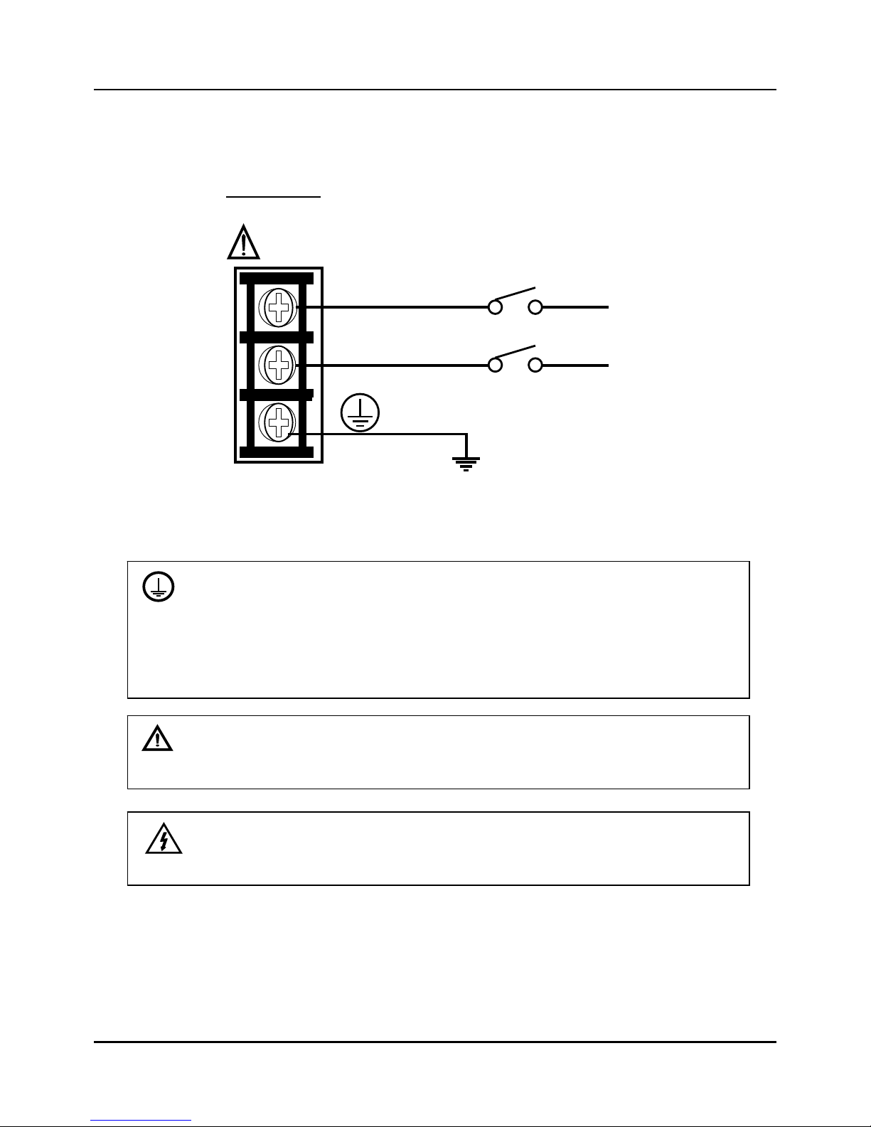
Wiring Diagrams
1) Connection of power supply
input terminal
Fig. 2.7.1 Mains Power Supply
PROTECTIVE BONDING (grounding) of this controller and the enclosure in which it is
installed shall be in accordance with National and local electrical codes. To minimize
electrical noise and transients that may adversely affect the system, supplementary bonding
of the controller enclosure to a local ground, using a No.12(4 mm
2
) copper conductor, is
recommended.
CAUTION
To prevent product damage and failure, do not connect power supply cable to PE
terminal.
WARNING
Make sure that wiring to the main power supply is disconnected from the site AC source
before installing wiring.
100~240VAC
50~60Hz
Earth Ground
L1(H)
L2(N)
Neutral
Hot
AC Line
Voltage
- 12 -
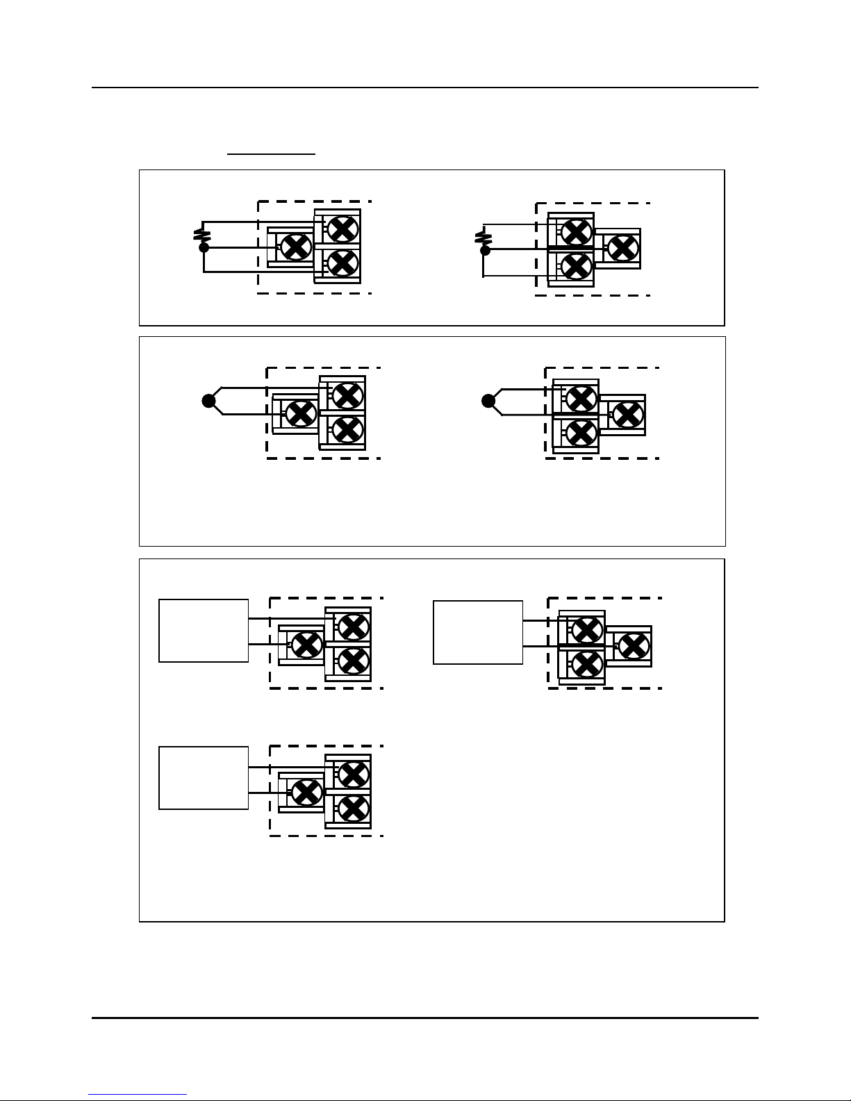
2) Connection of Analog input terminal
Fig. 2.7.2 Analog input 1 / input 2 Connections
For INPUT2 and INPUT3, these are NOT available for IPC5000S.
9
11
13
10
12
14
RTD (Resistance Temperature Detector) input
Input 1 Input 2
9
11
13
10
12
14
DC voltage or current input
Input 1 Input 2
Volt or
Milliampere
source
+
-
Volt or
Milliampere
source
-
+
15
16
Input 3
+
Volt or
Milliampere
source
-
* Be careful to connect the input polarities correctly.
9
11
13
10
12
14
Thermocouple input
Input 1 Input 2
+ +
-
-
* Be careful to connect the input polarities correctly.
- 13 -
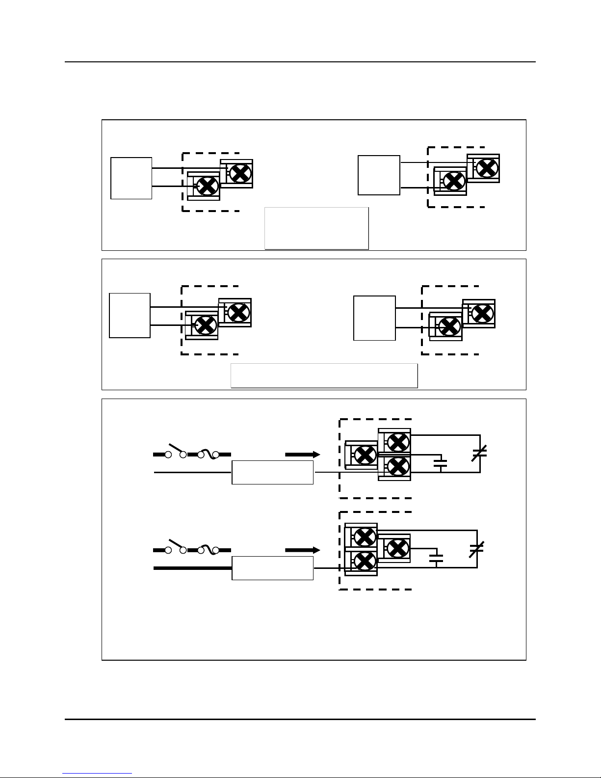
3) Connection of Universal control output
Fig. 2.7.3 Control output 1 / output 2 Connections
The ‘Voltage pulse output’ is not available for IPC5000S.
Relay outputs
[Note] Electromechanical relays are rated at 3 Amps at 240Vac. Customer should size fuses
accordingly. Use Fast Blo fuses only.
Output 1
15
17
16
N.C.
N.O.
Relay load
To terminal
16 or 15
Load
Supply
Power
Output 2
19 18
20
N.O.
N.C.
Relay load
To terminal
18 or 19
Load
Supply
Power
Current outputs (4~20mA)
Output 1
1
2
+
-
Load
Output 2
3
4
+
-
Load
4 to 20mA DC
Load resistance
Less than 600 Ω
Voltage pulse outputs
Output 2
3
4
+
-
SSR
Output 1
1
2
+
-
SSR
1 to 22mA DC
Open terminal voltage: Max. 25V DC
- 14 -
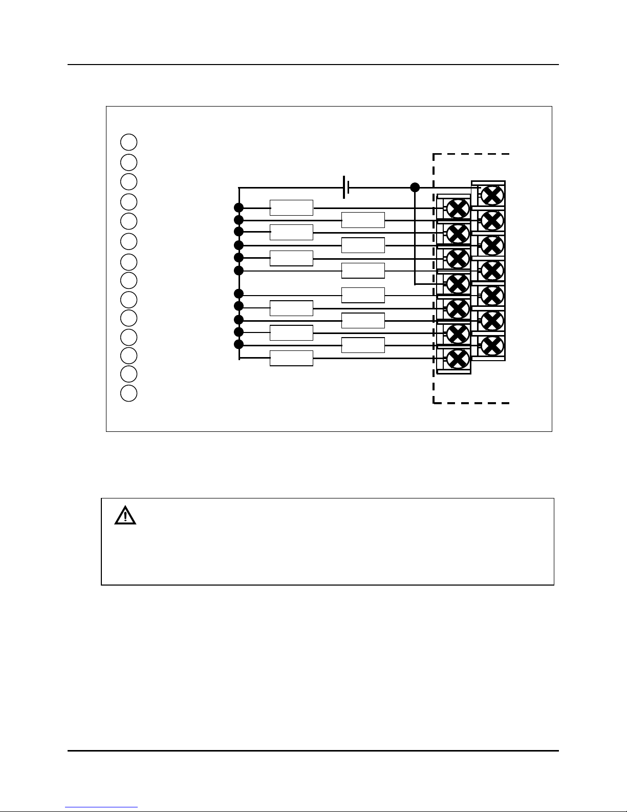
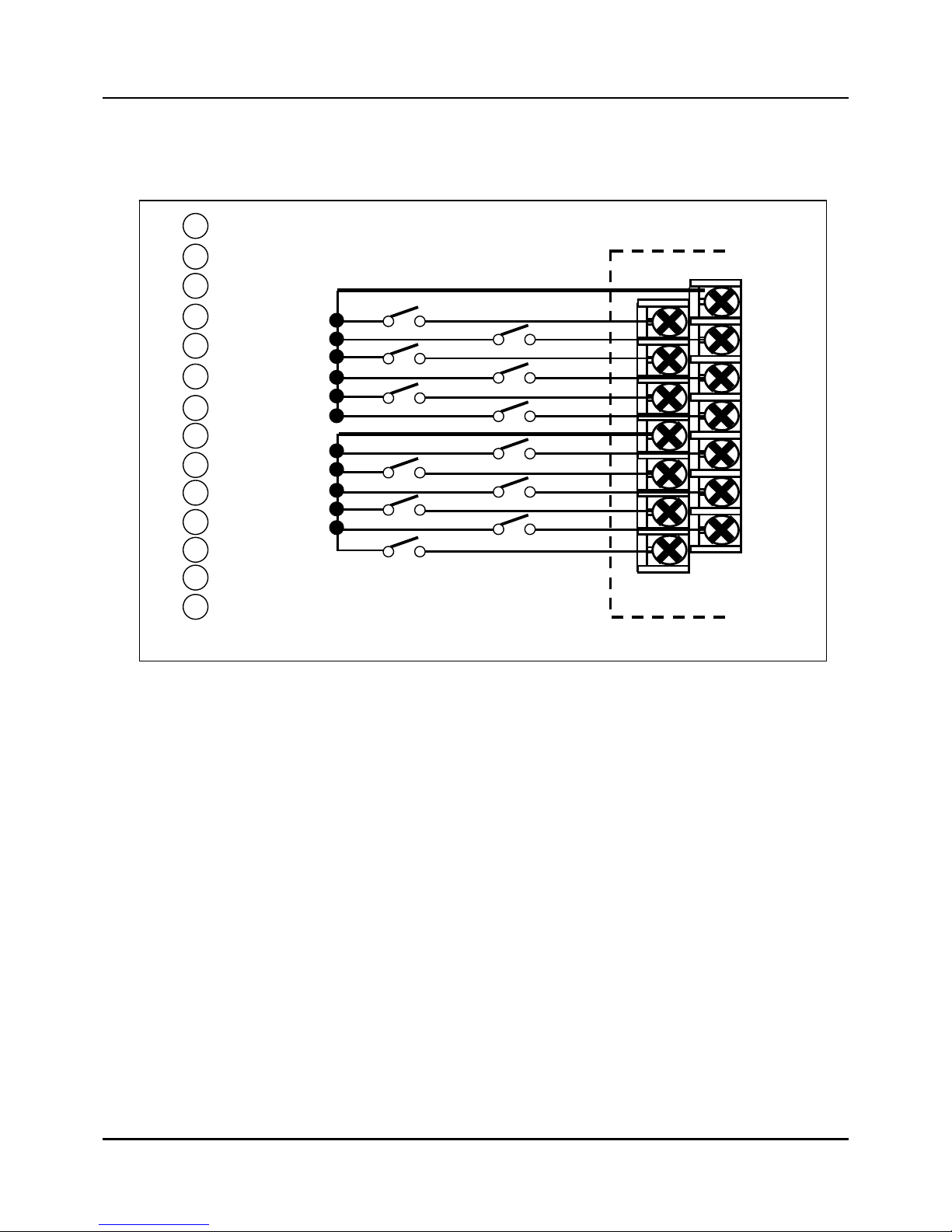
4) Connection of Digital outputs
Fig. 2.7.4 Digital outputs Connection
DO1
DO2
DO3
DO4
DO5
DO9
DO10
DO11
DO12
DO_COM1
DO6
2
DO_COM2
3
DO7
4
DO8
5
6
7
8
9
10
11
12
13
14
1
1
2
3
5
4
6
7
8
9
11
10
12
13
14
+
DC 24V
Load
Load
Load
Load
Load
Load
Load
Load
Load
Load
Load
Load
++-
+++-
+
++-
+++-
CAUTION
Open-collector output of IPC5000 is designed for 30VDC and less than 100mA. When
using a relay as a load, use a relay for 24VDC. 24 volt power supply needs supplied by
user. Supply should have a minimum current rating of 1.5A.
- 15 -
5) Connection of Digital input
Fig. 2.7.5 Digital inputs Connections
DI6
2
DI_COM
3
DI7
4
DI8
5
DI1
6
DI2
7
DI3
8
DI4
9
DI5
10
DI9
11
DI10
12
DI11
13
DI12
14
DI_COM
1
1
2
3
5
4
6
7
8
9
11
10
12
13
14
- 16 -
6) Connection of Auxiliary output (Option) – IPC5000D
Fig. 2.7.6 Auxiliary output 3 output 4 Connections
For Auxiliary output 3 and 4, these are NOT available for IPC5000S.
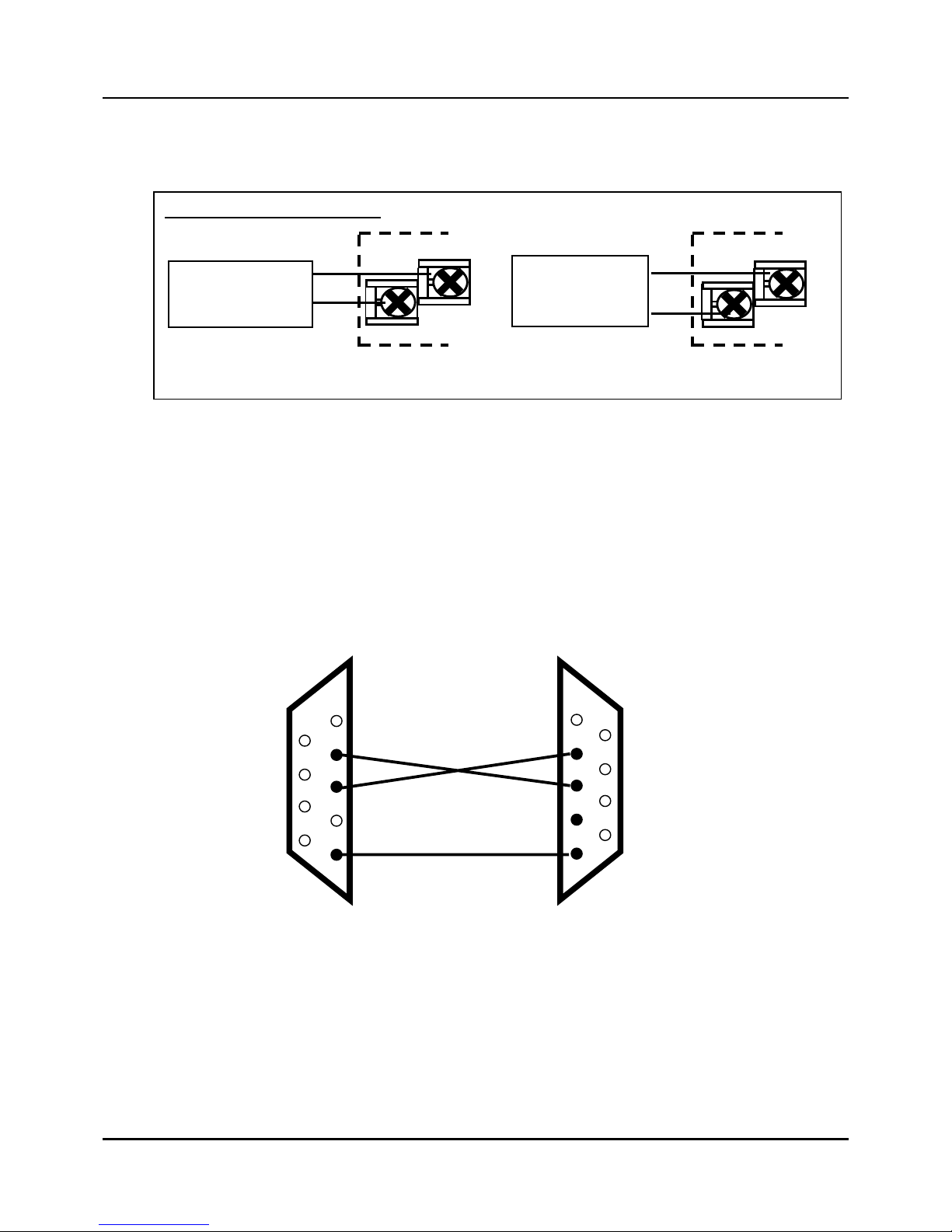
7) Connection of RS-232C communication
z 9 pin to 9 pin
Fig. 2.7.7 RS-232C communication 9 pin Connection
In this 3-wire cable, pin 2 and 3 should be crossed and pin 5 should be directly wired.
The length of the communication line between PC and IPC5000 should be 15m (49.2
ft.) or less.
Current outputs (4~20mA)
5
7
6
8
AUX. Output 3 AUX. Output 4
+
-
+
-
Load
(Max. 600Ω)
Load
(Max. 600Ω)
1
2
3
4
5
6
7
8
9
1
2
3
4
5
6
7
8
9
PC IPC5000
TXD TXD
RXD RXD
FG FG
- 17 -
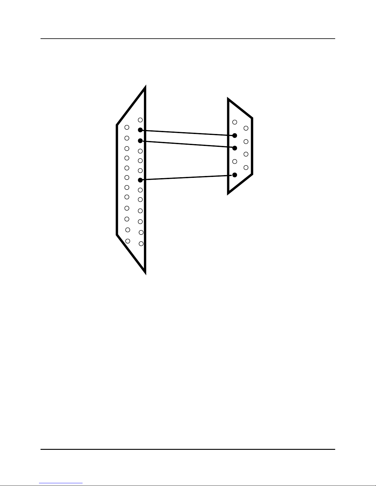
z 25 pin to 9 pin
Fig. 2.7.8 RS-232C communication 25 to 9 pin Connection
In this 3-wire cable pin 2 and 3 should be connected directly and pin 5 should
be directly wired to pin 7. The length of the communication line between PC and
IPC5000 should be 15m (49.2 ft.) or less.
1
2
3
4
5
6
7
8
9
PC
IPC5000
TXD
TXD
RXD
RXD
FG
FG
1
2
3
4
5
6
7
8
9
10
11
12
13
15
16
17
18
19
20
21
22
23
24
25
14
- 18 -
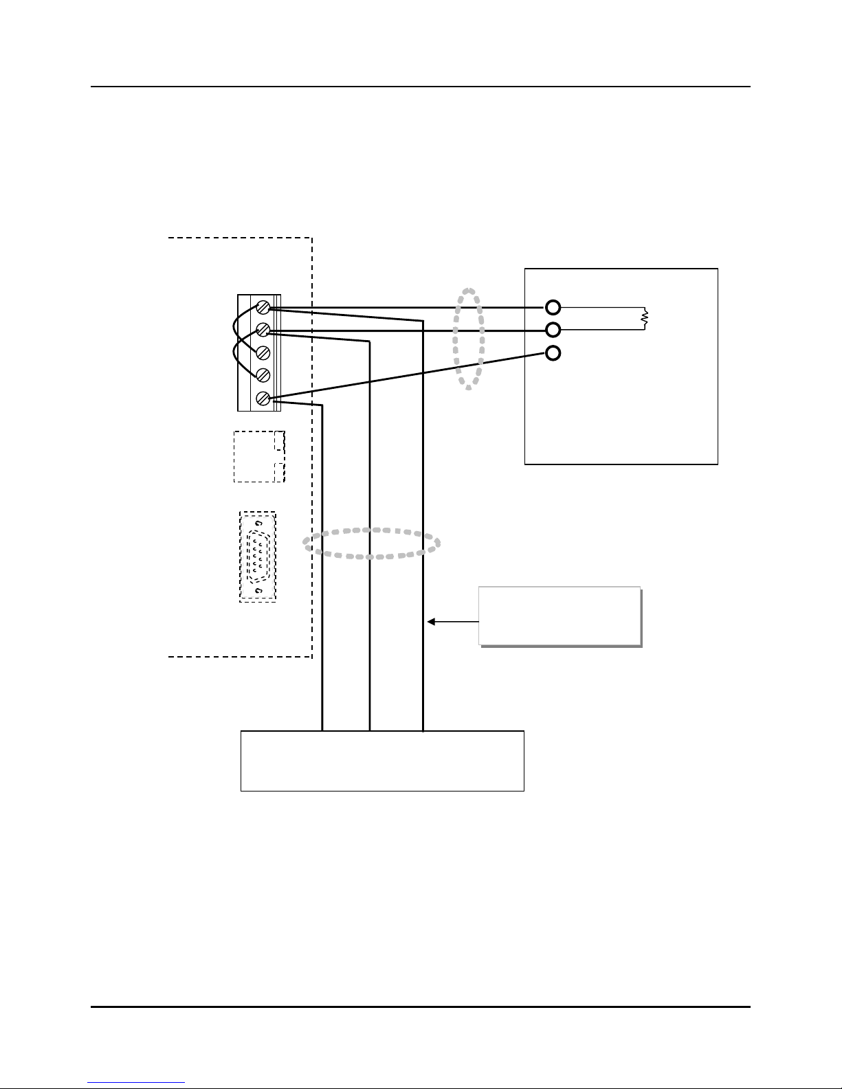
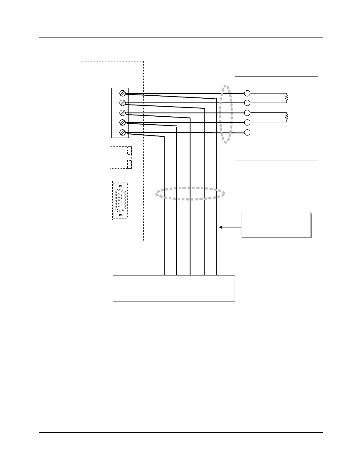
8) Connection of ModBus
The IPC5000 with the optional communication provides an RS 485 communications ports
with ModBus RTU protocol support.
Fig. 2.7.9 RS422/485/Modbus Communications Option Connections (3-Wire shield)
3-Wire
Shielded
SG
SDB
SDA
RDB
RDA
MODBUS
Master
RX+/TX+
RX-/TX-
SG
To other communication IPC5000
(Maximum 31)
* 120 Ohm Resistor on Last Leg
120 Ohm
Resistor
Do not run these lines in
the same conduit as AC
power
Use shielded
twisted pair cables
- 19 -
Fig. 2.7.10 RS422/485/Modbus Communications Option Connections (5-Wire shield)
5-Wire
Shielded
SG
SDB
SDA
RDB
RDA
MODBUS
Master
RX+
RX-
SG
To other communication IPC5000s
(Maximum 31)
* 120 Ohm Resistor on Last Leg
120 Ohm
Resistor
TX+
TX-
120 Ohm
Resistor
Do not run these lines in
the same conduit as AC
power
Use shielded
twisted pair cables
- 20 -
9) Connection of Ethernet (Option)
IPC5000 is available for data monitoring or operating on touch operation panel as HMI or PC
software by 1:1 or 1:N through Ethernet port, Protocol should be used Modbus TCP only.
Setup of Ethernet port
The setup of Ethernet port can be set on ‘3.20 NETWORK SET
’ screen, the seting parameters are
as following table.
Parameter for setup of Ethernet port
Setting parameter Range Remark
Protocol Modbus TCP : Fixed
FP Type FPB, FPLB, FPBB, FPL It is available for Universal Modbus only.
IP Address - Default=192.168.0.2
GATE way - Default =192.168.0.2
Sub net - Default =255.255.255.0
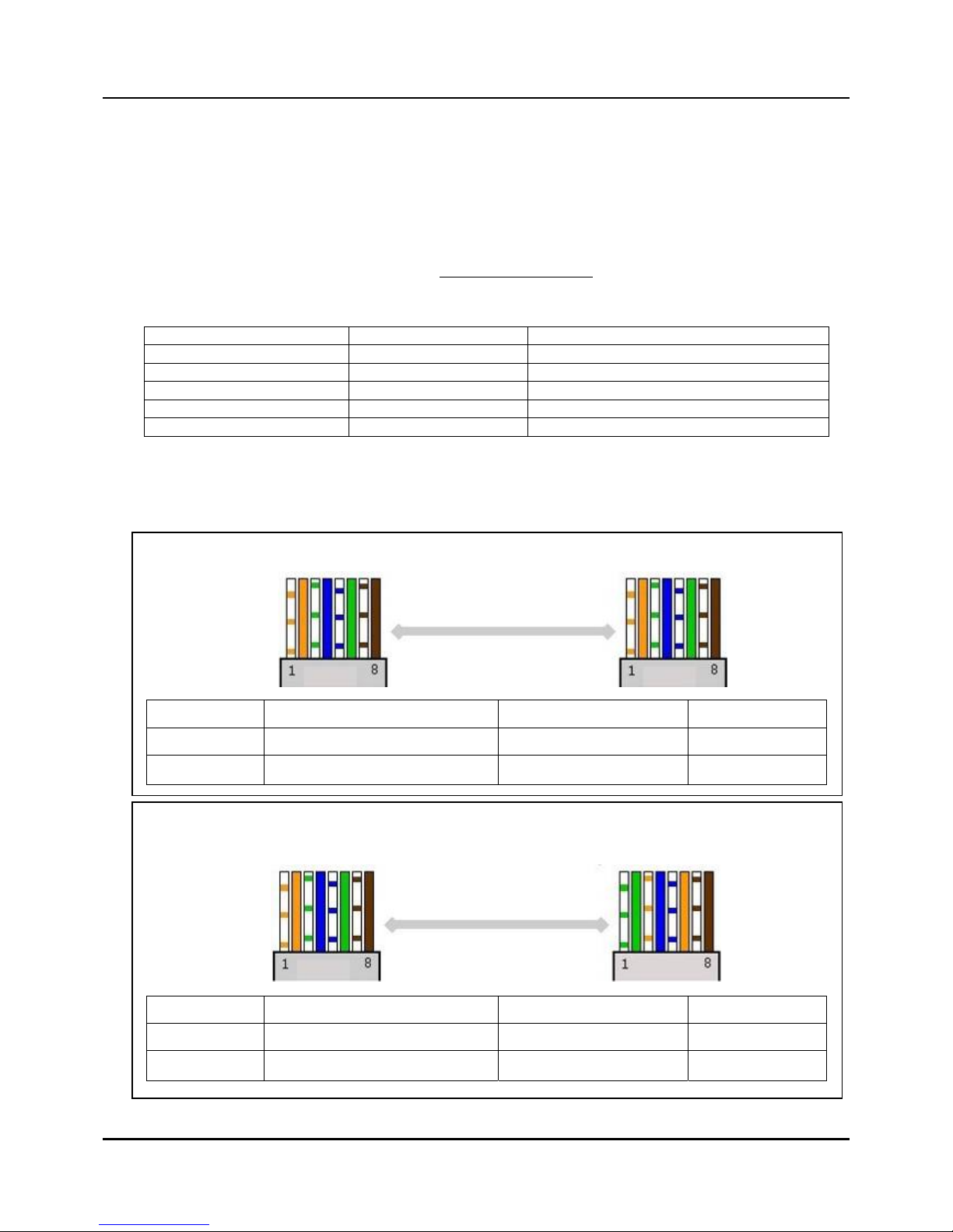
Wiring
For Ethernet Communication, it should be used as followings.
Direct cable(PC to HUB)
Output Input Remark
Transmitt(TX) Cable 1,2 Cable 1,2
Receiving(RX) Cable 3,6 Cable 3,6
Crossover cable
- In case of connection PC into IPC5000.
Output Input Remark
Transmitt(TX) Cable 1,2 Cable 3,6 Output
Receiving(RX) Cable 3,6 Cable 1,2 Input
 Loading...