


IPC500
PROGRAMMABLE
TEMPERATURE
CONTROLLER
Installation Manual

To our valuable customers
Special attention to the manual
1. Keep the manual for the last user who can get easy access to the
manual.
2. Make sure you read and understand the content of the manual then
operate the product.
3. This manual only explains detail information on how to use the product
effectively. Honeywell disclaims the implied warranties for particular
purpose.
4. Our company, Honeywell Korea is not responsible for any damages
caused by the user with careless.
5. This manual is not to be duplicated, re-edited or rent without
permission given by Honeywell Korea. It is subject to change without
notice.
6. If you have any queries or thought about this manual, please do not
hesitate to contact Honeywell Korea. We’ll try our best to get you an
answer.
Thank you for purchasing our IPC500(Programmable Temperature Controller)
This manual explains suitable effective way of using and installing this product.
Please read carefully to apply IPC500 to controller of temperature chamber or
others.

Description on indicator diagram
Following diagrams indicate potential dangers that may damaged the product
and harm your body. Please make sure you read and understand meaning of
following symbols before you read this manual.
Example of indicator
It indicates “Handle with care” which designed to avoid any
dangers that may risk one’s life and harm the machine.
It is a Frame Ground which means protection earth terminal.
Provided for connection of the protective earth.
(1) Indicates “Operating with care”
Learn and understand before operating.
(2) Indicates “Operating warning”
It may damage software or hardware.
System down may happen.
The manual contains following indicators.
Indicates “set-up is not available”
It explains about learning method before actual operating and
also explains how to be able to set up the condition
(1) Indicates “Additional description”
It explains techinical part which may be refered when set up.
(2) Indicates "Referential Description”
It explains referential part that the user can refer when set up
Indicator that used in the manual
For the safety

Checks when Unpacking
IPC500 series consists of the units on the table below.
When unpacking the product, check the following :
1. Model and parts numbers to ensure that you have received the product you ordered.
2. Unit appearance for damage.
3. That all accessories are included.
Caution on installation
After unpacking, store any unused accessories in a safe to avoid loss or damage.
If any of the accessories listed in the table below are missing, or the product has
been damaged during in shipping, immediately contact your Honeywell sales/service
office or the dealer from whom you purchased the equipment.
Model and parts Model and Parts No. Qt'y Remarks
IPC500
Basic Model No. :
IPC500-RE
LonWorks option
Model No. : IPC500-L
1
Metal fitting 2
Communication Software CD 1
RS-232 Communication
Software
IPC500 User Manual
IPC500 Installation Manual

1. Product summary
1.1 Name of Model
1.2 Terminal Layout Chart
1.3 Backside Terminal Layout
2. Installation and Connection
2.1 Installation Environment
2.2 Installation Suggestions
2.3 Panel Cut Dimensions
2.4 Installation of fixed Bracket
2.5 Terminal Connection Chart
3. IPC500 Setup
3.1 Composition of the Display Screen
3.2 CONTROL SET display
3.3 Display Screen for Setup of PID ZONE
3.4 Display for Setup of PID CONSTANT
3.5 INNER SIGNAL Setup Display Screen
3.6 INPUT SET Display
3.7 OFFSET & LonWorks Setup Display Screen
3.8 LANGUAGE Setup Display
4. Specifications
4.1 General Specifications
4.2 Input/Output Specifications
4.3 Program specifications
4.4 Control output specifications
4.5 Control output specifications(INNER Signal)
4.6 Control mode and setup
4.7 Other specifications
4.8 Trouble Monitor
4.9 External Dimensions
1
1
1
2
3
3
4
4
5
5~10
11
11
12~15
15~18
18~19
19~25
26~27
28
29
30
30
31
32~33
CONTENTS
33~34
34~35
35
36
37
38

- 1 -
1. Product Summary
1.1 Name of Model : IPC500
1.2 Terminal Layout Chart
No Name No Name No Name
21
22
23
A
B
B
Dry-bulb
temperature
Pt100Ω/
JPt100Ω
1
2
3
4
FG
NC
Power
24
25
26
NC
NC
NC
27
28
NC
NC
Analog
Input
41
42
43
44
45
46
47
48
49
50
51
COM
RUN/STOP
Trouble, signal 1
Trouble, signal 2
Trouble, signal 3
Trouble, signal 4
NC
Trouble, signal 6
Trouble, signal 7
NC
NC
Digital
Input
signal input specification
29
30
31
32
NC
COMMON
Temperature
Control Output
SSR
NC
Digital
Control
Output
33
34 +-
Temperature
Control Outpu
t
35
36
NC
NC
37
38 +-
Temperature
Current Value
Output
5
6
7
8
9
10
11
12
13
14
15
16
17
18
19
20
COM
NC
NC
RUN
END
NC
DOWN
TROUBLE
INNER SIGNAL1
INNER SIGNAL2
INNER SIGNAL3
INNER SIGNAL4
TIME SIGNAL 1
TIME SIGNAL 2
TIME SIGNAL 3
TIME SIGNAL 4
Digital
Output
(SSR)
39
40
NC
NC
Analog
Output
( 4 ~
20mA )
Signal 1
Signal 2
Signal 3
Signal 4
Signal 5
Signal 6
Signal 7
Signal 8
Signal 9
Invert
BLOWER
OVER TEMP
DRY TEMP
No Used
Freezer 1
Freezer 2
No Used
No Used
Additional Description
If you choose I.S. in SIGNAL SE LECT item in the CONTROL SET
display (Figure 3.2.1), TIME SIGNALS 1, 2, 3, 4 are utilized
as INNER SIGNAL 5, 6, 7, 8 (Terminal number 17, 18, 19, 20).
AC 85 ~ 264V

- 2 -
1.3 Backside Terminal Layout
Additional Description:
LonWorks in Figure 1.3.1 is optional. LonWorks part does not
operate for models that do not have LonWorks option.
Installation W arning:
♦ in Figure 1.3.1 is a part that is to fix the terminal stand
and is not a part of connect ion. In case you connect to
the part of ♦, such abnormal opera tion as sy stem dama ge
or malfunction may occur. Please be cautious.
<Figure 1.3.1> Terminal Layout
NC 5 6 7 8 9 10 11 12 13 14 15 16 17 18 19 20
21 22 23 24 25 26 27 28 29 30 31 32 33 34 35 36 37 38 39 40
41 42 43 44 45 46 47 48 49 50 51
RS-232C
CAUTION
IPC500
♦
♦
LON
A B
LonWorks
FG
AC85~264V

- 3 -
2. Installation and Connection
2.1 Installation Environment
Caution
To enhance reliability of the system and for IPC500’ s smooth functioning, please do
not install it in and under the following locations and conditions .
— Where the surrounding temperature is — Where corrosive or combustible gas
higher than 50°C exists
— Where there are direct rays of light — Where there are conductible materials
— Outdoors such as lots of dust, salt and steel scraps,
and organic solvents
— Where the temperature is below 0°C — Conditions that would expose it to vibration
and shocks
— Where humidity is over 85% — Where a strong electromagnetic field
— Where due is generated due to rapid exists
change of temperature
— Where water, oil or chemical materials
exist

- 4 -
2.2 Installatio n Sug gestions
Here, items to be cautioned at the time of installation of IPC500 (temperature
controller) to panel are explained. Protection from the environment and
convenience of operation needs to be considered.
1) Allow sufficient distance for ventilation.
2) Do not install it right above of equipment (transformer, large capacity resistor, etc.) that
generates a lot of heat in the panel.
3) Install it as far as possible from high voltage equipment and power-driven machinery or
wiring. Otherwise, install it in a different panel.
4) To reduce and prevent noise, please use special purpose grounding. If wiring to the point
of grounding is far, please use heavy insulation wire as a special purpose grounding
cable and ground it through a conduit tube.
5) For IPC500’s communication cable and data lines, do not tie it up together with those
that cause noise such as the power supply wiring of a power-driven machine. In case it is
wired to the same duct, connect shield wire to FG terminal of the main frame.
6) When installing panel, use a flat panel that is not curved.
7) To prevent product damage, fasten screws just once when bracket does not move back
and forth.
8) The Cooling method of IPC500 is based on vertical installation which needs natural air
cooling. In case it is installed horizontally or on a slant, range of operating temperature is
somewhat limited.
9) If you want to use it after keeping it under 0°C, you need to warm it up for two
hours at room temperature before plugging it in. Otherwise, it may not function
normally and the product may be damaged.
2.3 Panel Cut Dimensions
199.5
119
<Figure 2.3.1>
Unit: mm

- 5 -
2.4 Installation of fixed Bracket
Caution at the time of connection:
Before connecting IPC500, please be sure that the po wer supply is shut off.
Otherwise, there might be electric shock. Please be cautious.
2.5 Terminal Connection Chart
1) Connection chart of power supply input terminal
<Figure 2.4.1>
NC
85 ~ 264 VAC 50/60Hz
<Figure 2.5.1>
FG
AC85~264V

- 6 -
Installation Warning:
Please be sure to ground Frame Ground (FG) in Figure 2.5.1
Otherwise, an abnormal operation might occur .

- 7 -
2) Connection chart of digital input (SSR) terminal
Explanation for Reference
1. RUN output
— Terminal number: 8
— Content : Output is ON, when it is being operated .
In case operating mode is "STOP", "END", "READY",
"BREAK", or "TROUBLE" mode, output is OFF;
in case operating mode is "RUN", "HOLD", "WAIT", "COLD",
"HOT" mode, output is ON.
2. END output
— Terminal number : 9
— Content: Output is ON, if program control operation
is completed; otherwise, it is OFF.
Caution
The open collector output
of IPC500 is specified in
MAX 30 VDC, MAX 50mA,
internal resistance 47
Ω.
When the load is relay,
INNER SIGNAL1
8
INNER SIGNAL2
9
INNER SIGNAL3
10
INNER SIGNAL4
11
RUN
12
END
13
NC
14
DOWN
15
TROUBLE
16
TIME SIGNAL1
17
TIME SIGNAL2
18
TIME SIGNAL3
19
TIME SIGNAL4
20
COM
5
LOAD
LOAD
LOAD
LOAD
LOAD
LOAD
LOAD
LOAD
LOAD
LOAD
LOAD
LOAD
-
-
-
-
-
-
-
-
-
-
-
-
DC V
/(INNER SIGNAL 5)
/(INNER SIGNAL 6)
/(INNER SIGNAL 7)
/(INNER SIGNAL 8)
<Figure 2.5.3>

- 8 -
3. DOWN output
— Terminal number : 11
— Content: While the patte rn contr ol is operated, output is ON if the
set temperature point decreases as in Figure 2.5.4. Output is
maintained as ON until WAIT is over and becomes OFF when
WA IT is over. If it is operated by a fixed command control , it is OFF.
4. TROUBLE output
— Terminal number : 12
— Content :
If any of the digital ALARM input (1~9) (terminal number 43,44,45,
46, 47, 48, 49, 50, 51) is ON, TROUBLE outp ut is ON . To make
TROUBLE output OFF, you need to make ALARM input OFF and
press the “Clear” key in the troubleshooting display screen. At the time
when TROUBLE output occurs, all output except auxiliary (Present
value) output becomes OFF.
5. Output of 4 different types of Inner signals and Time signals
— Terminal Number:
INNER SIGNAL 1 → terminal 13 TIME SIGNAL 1 → terminal 17
INNER SIGNAL 2 → terminal 14 TIME SIGNAL 2 → terminal 18
INNER SIGNAL 3 → terminal 15 TIME SIGNAL 3 → terminal 19
INNER SIGNAL 4 → terminal 16 TIME SIGNAL 4 → terminal 20
— Content:
See reference explanation of Inner signal from p a ges 19 to 25
See reference explanation of Time signal from pages 28 to 30 in
“User Manual”
ON
ON
OFF OFF
<
Figure 2.5.4> DOWN SSR output ON-OFF

- 9 -
3) Digital control main output (SSR) terminal connection chart (PID control output)
4) Analog current control main output terminal connection chart (PID control output)
5) Analog current auxiliary output terminal connection chart
Present value output of temperature current (-)
NC
Present value output of temperature current (+)
37
38
39
NC
40
DC 4~20 mA
Receiver
-
<Figure 2.5.7>
Temperature control output
NC
COM
30
LOAD
31
32
DC V
<Figure 2.5.5>
Temperature current control output(-)
NC
Temperature current control output(+)
33
34
35
NC
36
DC 4~20 mA
Receiver
-
<Figure 2.5.6>

- 10 -
6) Analog input terminal connection chart
7) Digital input terminal connection chart
Installation Warning:
At the time of connection, please be sure to connect to the correct polarity.
If there is an error in the polarity connection, operation of ON/OFF and
current input and output may not be normal.
44
45
RUN/STOP
46
47
48
49
TROUBLE 4
50
51
COM
41
TROUBLE 1
TROUBLE 2
TROUBLE 3
NC
TROUBLE 6
TROUBLE 7
NC
NC
42
43
<Figure 2.5.9>
A
B
22
B
23
24
25
26
Dry bulb temperature
RTD
<Figure 2.5.8>
NC
NC
NC

- 11 -
3. IPC500 Setup
The initial setup should make it appropriate for the control of the function and capacity of the
temperature chamber. It is composed and operated as shown in Figure 3.1.1.
3.1 Composition of the Display Screen
Composition of the display screen is based on ROTATION mode (Figure 3.1.1).
T o enter into the init ial disp lay screen (Display to set CONT ROL SET), touch the
upper right in the main display screen and push the monitor key within one
second.
CONTROL SET screen
Main screen
Press MONITOR key in a second
after pressing the key on the top right
INPUT SET screen
OFFSET & LonWorks
screen
NEXT
NEXT
EXIT
EXIT
EXIT
<Fi
g
ure 3.1.1>
Menu screen
Korean/English/Chinese
conversion screen
Press the bottom left in a second
after pressing the key on the top
EXIT
NEXT

- 12 -
3.2 CONTROL SET display
This display screen is used to set up such items as the output mode of temperature
control, DIGITAL output, PID related items, and AUTO TUNING.
Sequence of Operation
1. Setting up the temperature control output mode
It allows you to choose to make the temperature control output mode either in direct or
reverse motion.
— To choose reverse motion
Enter REVERSE key (1). If you choose the REVERSE key, the key is reversed
from a white background with blue characters to a blue background with white
characters.
— To choose direct motion
Enter DIRECT key (1). If you choose the DIRECT key, the key is reversed.
Key to go to PID ZONE
setup screen
(1) Temperature reverse/direct
operation select key
(3) SIGNAL type select key
(4) SIGNAL output form display
(5) AUTO TUNING MAN/AUTO
select key
EXIT
CONTROL SET
REVERSE DIRECT
I.S/T.S I.S
I.S(4) T.S(4
)
PID
ZONE
PID
CONSTANT
INNER
SIGNAL
MAN AUTO
10
ESC
-
0 5 16273849. ENT
SEC
NEXT
<Figure3.2.1>
Return to menu screen
Converted to INPUT SET screen
Key to go to PID
constant setup
screen
Key to go to INNER SIGNA
L
setup screen
(6) TROUBLE delay time
setup key

- 13 -
Additional Description
Direct operation/ reverse operation explanation
1. Direct operation: freezing
2. Reverse operation: heating
Proportional band
SP
PV hi
g
h
Te mperature
Cycle Time
OFF time
ON time
<Figure3.2.2> Temperature Direct operation Output
Proportional band
SP
PV high
Temperature
Cycle time
OFF time
ON time
<Figure3.2.3> Temperature Reverse operation Output

- 14 -
3. Setting up INNER(4)/TIME(4) SIGNAL or INNER(8) SIGNAL
Generally, IPC500’s outputs are 4 INNER SIGNALs and 4 TIME SIGNALs.
However, you can use up to 8 INNER SIGNALs
(but 4 TIME SIGNALS cannot be utilized if 8 INNER SIGNALs are used).
— Setting up outputs as 4 INNER SIGNALs and 4 TIME SIGNALs
Push I.S/T.S key (3) shown in Figure 3.2.1. If you choose I.S/T.S, the key is
reversed and SIGNAL output mode indicator (4) is shown as "I.S(4) T.S(4)".
— Setting up output as 8 INNER SIGNALs
Push I.S key (3) shown in Figure 3.2.1. If you choose I.S, the key is reversed
and SIGNAL output mode indicator (4) is shown as "I.S(8)."
Additional Description
Terminal numbers by selecting I.S/T.S Terminal numbers by selecting I.S
INNER SIGNAL 1 → Terminal number : 13 INNER SIGNAL 1 → Terminal number : 13
INNER SIGNAL 2 → Terminal number : 14 INNER SIGNAL 2 → Terminal number : 14
INNER SIGNAL 3 → Terminal number : 15 INNER SIGNAL 3 → Terminal number : 15
INNER SIGNAL 4 → Terminal number : 16 INNER SIGNAL 4 → Terminal number : 16
TIME SIGNAL 1 → Terminal number : 17 INNER SIGNAL 5 → Terminal number : 17
TIME SIGNAL 2 → Terminal number : 18 INNER SIGNAL 6 → Terminal number : 18
TIME SIGNAL 3 → Terminal number : 19 INNER SIGNAL 7 → Terminal number : 19
TIME SIGNAL 4 → Terminal number : 20 INNER SIGNAL 8 → Terminal number : 20
4. Setting up AUTO TUNING MAN/AUTO
It allows you to set it up so that you can or cannot execute AUTO TUNING in the
operating display.
— To select AUTO TUNING MAN
Push MAN key (5) in Figure 3.2.1. If you choose MAN key, the key is
reversed.
When MAN key is selected, ( TEMP ) AUTO TUNING execution key
does not appear in the monitor screen and you cannot execute AUTO TUNING.
— To select AUTO TUNING AUTO
Push AUTO key (5) in Figure 3.2.1. If you choose AUTO key, the key is reversed.
If AUTO key is set up, ( TEMP ) AUTO TUNING execution key
appears in the monitor screen, which allows you to execute AUTO TUNING.

- 15 -
5. Setting up TROUBLE input delay time
If there are TROUBLE inputs, TROUBLE output and message operate after set delay
time. Range of delay time to be set is between 1 and 99 second(s).
— When key (6) is pressed, the numeric keyboard appears. If you enter delay
time and hit ENT key, it is set up; if you enter ESC key, it is cancelled.
3.3 Display Screen for Setup of PID ZONE
There can be up to 6 ZONEs for the range of temperature PID constant
and they are controlled by the PID constants in the ZONE field in which set points (SP)
of temperature exist.
Initial setup at the time of product shipment is ZONE 1 fields and all fields are controlled
by a single PID constant.
EXIT
PID ZONE
<Figure 3.3.1>
Return to CONTROL SET screen
T1
DISP
(1) Temperature ZONE
classifying constant T1
setup key
(2) Temperature ZONE
classifying constant T2
setup key
(6) ZONE range
redrawin
g
key
(3) Temperature ZONE
classifying constant T3
setup key
=
-50
T2 =
0
T3 =
50
T4 =
100
T5 =
200
(4) Temperature ZONE
classifying constant T4
setup key
(5) Temperature ZONE
classifying constant T5
setup key

- 16 -
Sequence of Operation
1. If each of T1 key (1), T2 key (2), T3 key (3), T4 key(4), T5 key(5) is entered,
the numeric keyboard appears in the lower-hand side of the display. If you enter
the temperature that you want to set and then hit the ENT key, it is set up; if you enter
the ESC key, it is cancelled.
2. If you enter DISP (6) key after executing the sequence of operation 1, it draws a figure
again that divides the field in Figure 3.3.1 according to the changed ZONE field.
3. Temperature range setup for T1 ~ T5 is between -100 and 300°C.
Additional Description
ZONE divisional setup screen
1. Case of maximum 6 Zones
Divided into 1 to 6 zones based upon the setup of T1,T2,T3,T4,T5 in the needs of 6 Zones.
2. Case of 1 ZONE
Setup: T1 = 300, T2 = 300, T3 = 300,T4 = 300,T5 = 300 (product prevalues)
1
T2
T3
300°C
-100°C
Divided into 6 zones and
setup temperature
Temperature SP → High
2 3 4 5 6
T1
T4
T5
1
T2
T3
300°C
-100°C
Temperature SP → High
T1
T4
T5

- 17 -
3. Case of 2 ZONE
Set T2=T3=T4=T5=300 and T1will be the temperature at the setup which distinguishes zone.
4. Case of 3 ZONE
Set T3=T4=T5=300 and T1 and T2 will be the temperature at the setup which distinguishes zone.
5. Case of 4 Zone
Set T4=T5=300 and T1, T2 and T3 will be the temperature which distinguishes zone.
1
T2
T3
300°C
-100°C
Temperature SP → High
T1
T4
T5
2
1
T2
T3
-100°C
Temperature SP → High
2 3
T1
T4
T5
300°C
1
T2
T3
300°C
-100°C
Temperature SP → High
2 3 4
T1
T4
T5

- 18 -
6. Case of 5 ZONE
Setup is T5 = 300. T1,T2,T3 and T4 will be the temperature which distinguishes zone.
Invalid Setup:
At the time of setting up T1,T2,T3,T4 and T5, T1 ≥ T2 ≥ T3 ≥ T4 ≥ T5 is
invalid and cannot be entered.
3.4 Display for Setup of PID CONST ANT
It sets up P, I, D, ARW constants in each ZONE field. The PID constant that results
after completion of AUTO TUNING is applied to the appropriate ZONE field.
1
T2
T3
300°C
-100°C
Temperature SP → High
2 3 4 5
T1
T4
T5
PID CONS
T
A
NT
<
>
Return to CONTROL SET screen
P(%) I(Min) D(Min) ARW(%)
TEMP 1.00 1.20 0.30 000
TEMP 1.00 1.20 0.30 100
TEMP 1.00 1.20 0.30 000
TEMP 1.00 1.20 0.30 000
TEMP 1.00 1.20 0.30 000
TEMP 1.00 1.20 0.30 100
1
3
5
Indicate that the PID constant of what
zone is controlling
EXIT
2
4
6

- 19 -
Sequence of Operation
1. When you press any of keys, you will see a numeric keyboard in the screen below
and when you will insert any of PID and ARW constants in the input and press
the enter key, the setup will be all set, but if you press the ESC key the task will be
cancelled.
2. Early PID and ARW constants of every zone are setup as below:
P = 1.00 %, I = 1.20 Min, D = 0.30 Min, ARW = 100 %
3. constant setup boundary
P (Proportional band) : 0.0 ~ 99.99 %
I (Integral time) : 0 ~ 36.00 Min
D (Derivative time) : 0 ~ 36.00 Min
ARW : 0 ~ 100 %
3.5 INNER SIGNAL Setup Display Screen
This is a part which setups the INNER SIGNAL output items among DIGITAL outputs.
<Figure3.5.1>
EXIT
INNER SIGNAL1
TEMP
ITEM
(2) Object
select key
(3) Object value
select key
(5) Output operation selection key
Return to CONTROL SET screen
P
V
SP
DV
A
BS DEV
RANG
LOW HIGH
LEVEL
ABS VALUE 0.0 -100 ~ 300°C
OPER DIFF 0.0 0 ~ ±9.9°C
DELAY(SEC) 0 0 ~ 99 SEC
PAGE
(1) Page conversion key
A
BS DEV
A
BS
LOW HIGH
OFF ON
(4) Operating point selection key
TYPE→ PV
TYPE→ SP or DV
TYPE → PV
TYPE → SP or DV
(6) Absolute value,
Deviation value,
Minimum value
setup key
(7) Operation differential,
Maximum value
setup key
(8) ON/OFF DELAY time
setup key

- 20 -
Sequence of Operation
1. Setting up temperature(TEMP)/PV/ABS/HIGH, Absolute value (ABS VALUE),
Operation Differential (OPER DIFF), and DELAY(SEC)
— Press PV at object value selection key (3). The PV key is reversed.
— Press ABS at operating point selection key (4). The ABS key is reversed.
— Press HIGH at output operation selection key (5). The HIGH key is reversed.
— Enter absolute value after pressing ABS VALUE setup key (6). Input of ABS
VALUE is allowed only within SET RANGE on the right-hand side.
(Set range : -100 ~ 300°C)
— Enter operation differential after pressing OPER DIFF setup key (7). Input of
OPER VALUE is allowed only within SET RANGE on the right-hand side.
(Set range : 0 ~ ±9.9°C)
— Enter delay time after pressing DELAY time setup key (8). Input of DELAY time
is allowed only within SET RANGE on the right-hand side.
(Set range : 0 ~ 99 SEC)
2. Setting up TEMP/PV/DEV/HIGH, deviation value (DEV VALUE), OPER DIFF, and
DELAY(SEC)
— Press TEMP at object selection key (2). The TEMP key is reversed.
— Press PV at object value selection key (3). The PV key is reversed.
— Press DEV at operating point selection key (4). The DEV key is reversed.
— Enter HIGH at output operation selection key (5). The HIGH key is reversed.
— Enter deviation value after pressing DEV VALUE setup key (6). Input of
deviation value is allowed only within SET RANGE on the right-hand side.
( Set range: -99.9 ~ 99.9°C)
— Enter operation difference after pressing OPER DIFF setup key (7). Input of
operation differential is allowed only within SET RANGE on the right-hand side.
(Set range : 0 ~ ±9.9°C)
— Enter delay time after pressing DELAY time setup key (8). Input of delay time
input is allowed only within SET RANGE on the right-hand side. (0 ~ 99 SEC)
3. Setting up TEMP/SP/ABS/ON, minimum value (MIN VALUE), maximum value(MAX
VALUE), and DELAY(SEC)
— Press TEMP at object selection key (2). The TEMP key is reversed.
— Press SP at object value selection key (3). The SP key is reversed.
— If you choose SP, the ABS key is automatically selected.
— Press ON at output operation selection key (5). The ON key is reversed.
— Enter minimum value after pressing MIN VALUE setup key (6). Input of MIN
VALUE is allowed only within SET RANGE on the right-hand side.
(Set range : -100 ~ 300°C)

- 21 -
— Enter maximum value after pressing MAX VALUE setup key (7). Input of MAX
VALUE is allowed only within SET RANGE on the right-hand side.
(Set range : -100 ~ 300°C)
— Enter delay time after pressing DELAY time setup key (8). Input of DELAY time
is allowed only within SET RANGE on the right-hand side. (0 ~ 99 SEC)
4. Setting up TEMP/DV/ABS/ON, MIN VALUE, MAX VALUE, and DELAY(SEC)
— Press TEMP at object selection key (2). The TEMP key is reversed.
— Press DV at object value selection key (3). The DV key is reversed.
— If you choose DV, the ABS key is automatically selected.
— Press ON at output operation selection key (5). The ON key is reversed.
— Enter minimum value by pressing MIN VALUE setup key (6). Input of MIN VALUE
is allowed only within SET RANGE on the right-hand side.
(Set range : -100 ~ 300°C)
— Enter maximum value by pressing MAX VALUE setup key (7). Input of MAX VALUE
is allowed only within SET RANGE on the right-hand side.
(Set range : -100 ~ 300°C)
— Enter delay time by pressing DELAY time setup key (8). Input of DELAY time is
allowed only within SET RANGE on the right-hand side. (0 ~ 99 SEC)
Invalid Setup
At the time of setting up MIN VALUE and MAX VALU E of SP and DV,
MIN VALUE > MAX VALUE is invalid and cannot be entered.
Please enter MIN VALUE after entering MAX VALUE.
- 22 -
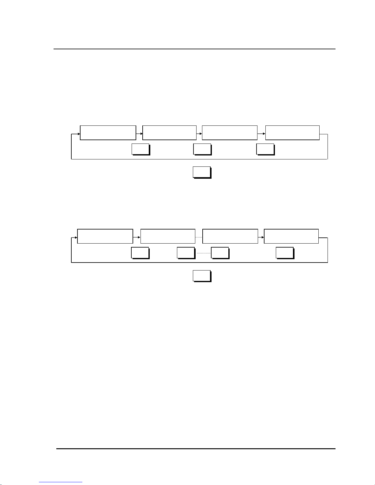
6. PAGE Conversion for INNER SIGNAL Setup Screen
In the first conversion screen, it is converted to the display in which INNER SIGNAL
NO.1 is set up. To set up INNER SIGNALs of other numbers, you need to press
PAGE key in Figure 3.5.1. Sequence of conversion at the time of key operation is
shown in Figure 3.5.2 and Figure 3.5.3.
INNER SIGNAL1 INNER SIGNAL2 INNER SIGNAL3 INNER SIGNAL4
PAGE PAGE PAGE
PAGE
<Figure3.5.2> Screen conversion when selecting I.S/T.S
INNER SIGNAL 1 INNER SIGNAL 2 INNER SIGNAL 7 INNER SIGNAL 8
PAGE PAGE PAGE
PAGE
<Figure3.5.3> Screen conversion when selecting I.S
PAGE

- 23 -
Additional Description
INNER SIGNAL Explanation
1. Contents
— ON / OFF open collector output × 4 or × 8
— Can be used optionally for cooling and signal control output.
— Each output is independent and sets up temperature, present value/
set point / target value, absolute value / deviation, output operation
(LOW / HIGH), and output operation (ON / OFF)
2. Setup of various operations: Various operations can be set up by combining items below.
— Object : TEMP → It allows you to set up if the object of operation is temperature.
— Object value : PV / SP / DV → It allows you to set up at what point it is ON and OFF.
PV : Present Value
SP : Set Point (Target value that changes synchronously as the PROGRAM
proceeds)
DV : Step’s target value (within a step, a fixed value is maintained)
— Operating point : ABS / DEV → sets up absolute value(ABS) and deviation(DEV).
Only PV allows you to set up. When SP and DV are set, it is fixed
as ABS.
— Output operation : ON / OFF → ON/OFF is set up for operating point in absolute
value that is set up next in case object value is SP and DV.
TEMP PV
SP
DV
Present Value
Set Point
Step
target value
ABS
DEV
Absolute
value(operating
Deviation
HIGH
LOW
Absolute value
(ABS VALUE)
Operation
Differential
(OPER DIFF)
DELAY
HIGH
LOW
DELAY
ON
OFF
ABS
Absolute
value(operating
point)
Minimum value
(MIN VALUE)
DELAY
ABS
Absolute
value(operating
ON
OFF
Deviation
(DEVIATION)
1
2
3
4
5
6
7
8
<Figure5.3.4> Block chart when selecting INNER SIGANL
Maximum value
(MAX VALUE)
Operation
Differential
(OPER DIFF)
Minimum value
(MIN VALUE)
DELAY
Maximum value
(MAX VALUE)

- 24 -
LOW / HIGH → If object value is PV, direction in which it is
turned ON is set up for the point that is set up next.
LOW :
Output is OFF when the reverse operation (heating) PV is
at a high temperature output OFF.
HIGH : Output is ON when the direct operation (freezing) PV is
at a high temperature output ON.
3. Operation range : Setup items vary depending on the operation types.
— Case of PV / ABS (Setup : LOW or HIGH range)
Absolute value (operating point) , Operation differential, DELAY time.
— Case of PV / DEV (Setup: LOW or HIGH range)
Deviation, Operation differential, DELAY time.
— Case of SP and DV (Setup: ON or OFF range)
Maximum value, Minimum value, DELAY time.
— DELAY time : The delay time of setup is over-lapsed until it becomes ON or OFF
condition setup, the output comes out. Within DELAY time, if the
conditions are cancelled, there will be no output.
4. Example case of PV, DEV selection
— Operation direction = LOW
— Operation direction = HIGH
▲
SP
- deviation
OFF
ON
PV → high
▲
SP
+ deviation
OFF
ON
PV → high
Operation differential
Operation differential
▲
SP
- deviation
OFF
ON
PV → high
▲
SP
+ deviation
ON
PV → high
OFF
Operation differential
Operation differential

- 25 -
5. Example in Case of PV, ABS selection
— Operation direction = LOW — Operation direction = HIGH
6. Example in case of SP and DV selection
30
20
10
0
-10
-20
Maximum
value
IS4
IS3
IS2
IS1
ON
range
SP (°C)
DV
setup
SP
setup
IS1
IS2
IS3
IS4
IS1
IS2
IS3
IS4
Minimum
value
-30
-40
O
N
ON ONONONO
N
O
N
O
N
ABS
OFF
ON
Operation differential
PV → high
setup
ABS
OFF
ON
PV → high
setup
Operation differential

- 26 -
3.6 INPUT SET Display
It is the display in which the cycle time of the control output, output range of current
temperature value, temperature set range, sensor selection are setup.
Sequence of Operation
1. Setting up control cycle
— Numeric keyboard appears, if you press control cycle time setup key (1). It is set
up if you enter control cycle and push ENT key; it is cancelled if you enter ESC
key. Control cycle time is shown in Figure 3.6.2.
2. Setting up output range of current temperature value
— Numeric keyboard appears, if you press the left-hand side button of the
current temperature value output range setup key (2). Please enter minimum
value of scale which is 4mA.
O
N
ON
75%
25%
Control Cycle Time (Sec)
<Figure 3.6.2> MV = 75% out
OFF
EXIT
INPUT SET
(2) Temperature present
value output range
setup key
2
CONTROL CYCLE
SEC
NEXT
(4) Sense selection key
(1) Control cycle time
setup key
Return to the menu screen
Converted to RANGE SET screen
-100.0
SCALING
~
300.0
°C
Pt
SENSOR SELECT
JPt
<Figure 3.6.1>
ESC
-
0516273849.
ENT
-100.0
TEMP SET
300.0
~
°C
(3) Temperature input range
setup key

- 27 -
— Numeric keyboard appears, if you press the right-hand side key of key (2). Please
enter maximum value which is 20mA.
— The range of SCALING setup is between 4 and 20mA and output of temperature
current value depends upon current temperature(PV).
Example) When SCALING setup range is between 0°C and 90°C, output of
current temperature value is 4mA if current temperature is below 0°C;
output of current temperature value it is 20mA if the current temperature is
above 90°C; if the current temperature is between 0°C and 90°C, output of
current temperature value is between 4mA and 20mA. (Initial SCALING
setup at the time of product shipment is between -100.0°C and 300.0°C)
3. Setting up the range of temperature input
It allows you to limit the range of Set Point for fix control and program control. If the user
enters SP that is out of the range of input field, an OVER RANGE message appears and
indicates that it cannot be set up.
— If you press the left-hand side key of temperature input range setup key (3),
the numeric keyboard appears. Please enter the minimum value of the input limit
field.
— If you press the right-hand side key of temperature input range setup key (3),
the numeric keyboard appears. Please enter the maximum value of the input limit
field.
4. Selecting Sensor Input
It allows you to select if you want to input a dry bulb /a wet bulb temperature either as
Pt100 or JPt100
— Selecting Pt100
If you press Pt key (4), the Pt key is reversed.
— Selecting JPt100
If you press JPt key (4), the JPt key is reversed.
Invalid Setup
At the time of setting up MIN VALUE and MAX VALUE,
MIN VALUE > MAX VALUE is invalid and cannot be entered.
Please enter MIN VALUE after entering MAX VALUE.

- 28 -
3.7 OFFSET & LonWorks Setup Display Screen
The part is adjusting the dry bulb temperature OFFSET and sending service pin number.
Sequence of Operation
1. Adjusting temperature OFFSET of a dry bulb temperature
— If you press dry bulb temperature OFFSET setup key (1),
the numeric keyboard appears. Please enter OFFSET value of a dry bulb
temperature.
— If input mode is DRY/DC or DRY/WET mode, both are valid.
Example) Let’s say that the actual input is 50.0°C. If OFFSET value is set up as
+1.00°C, the current value PV becomes 51.00°C and is adjusted
upward for the +1°C.
If OFFSET is set up as -1.00°C, it becomes 49.00°C and is adjusted
downward for the -1°C. Adjusted PV value is indicated as adjusted
current value of dry bulb temperature key (3).
— Input range : -9.99 ~ +9.99°C
2. Sending service pin No.
— When the Host request the service pin No. of IPC500, you press Send key(2).
Then, IPC500 send the pin No.
(3) Display dry bulb
temperature adjusted
by adding OFFSET value
EXIT
OFFSET & LonWorks
NEXT
(1) Dry bulb temperature
OFFSET
Return to the menu screen
Converted to CONTROL SET screen
0.00
DRY TEMP
°C
50.0
°C
<Figure 3.7.1>
OFFS
ET DISPLAY
Send
Se
rvice
ESC - 0 5 16273849.
ENT
(2) Button sending service pin

- 29 -
3.8 LANGUAGE Setup Display
It is a display that enables you to choose the language.
EXIT
LANGUAGE
English / Korean / Chinese conversion key
Return to the menu screen
<Figure 3.9.1>
ENGLISH
KOREAN
CHINESE

- 30 -
4. SPECIFICATIONS
4.1 General Specifications
Item Specifications
Temperature input range -100.0~300.0°C
Indicator Dot matrix LCD module
Display screen 86.37(H)X115.17(W)mm
Number of dots 240(H)X320(W) dot
Back light CCFL cathode type fluorescent lamp (Brightness : 100 cd/m2)
Display size 40 lines X 30 lines ( case of 8X8 dot characters)
Display
device
Display color Blue characters on a white ground
Setup method Touch key method
A/D conversion
Dual integral method
15bit (0.01 resolution with 300°C span)
Indication temperature ± 0.1%FS ± 1digit
Measure display 0.01°C / 0.1°C display switch available
Input sampling cycle 0.5 second
Clock accuracy ± 10 PPM(25°C standard), temperature specificity -10~70°C:+10/-120 PPM)
Backup
Program data, control stated number : nickel manganese secondary battery
Data is preserved for 5 years after break-off of power supply (provided that
Full Charge is preceded)
Initial set value EEPROM storage, more than ten years
Power voltage
Power frequency
AC 85 ~ 264 V
50/60Hz
Isolation resistance 50MΩ min. between case and terminals using a 500V DC Mega
Withstand voltage AC1500V, 1 min, between case and power terminals
Ambient temperature 0 ~ 50°C
Exterior Case: steel painting (ivory), front panel : plastic
Mounting Panel-mount
Exterior size 210mm(H)X130mm(W)X188mm(D)
Panel cut 199.5mm(H)X119mm(W)

- 31 -
4.2 Input/Output specifications
Item Specifications
PV input Pt100 or JPt100
RUN/STOP input Contact input X 1 (Program RUN/STOP external signal)
Trouble signal
Contact input X 6 (Display 6 items per screen)
Control output all OFF with Trouble signal input
Individual measure message, maximum 6 screens
Temperature
PID
Open collector output X 1
Temperature
PID
DC 4~20mA output X 1(Within load resistance 500Ω)
Control
output
Note 1) Operation direction direct operation(freezing) / reverse operation(heating)
Changeable.
Note 2) Open collector /DC4~20mA simultaneous output.
INNER SIGNAL
ON / OFF open collector out X 4 or X 8
Inner signals can be used at the freezing and Alarm Control
Each output is independently temperature, PV / SP / DV,
Absolute value / Deviation, Output operation LOW / HIGH, Output
operation ON / OFF, expansion of output X4 or out X8 when selecting
output (In use of INNER SIGNAL 8 kind TIME SIGNAL can be out of
use)
RUN output Open collector output X 1
END output Open collector output X 1
TIME SIGNAL Open collector output X 4
DOWN output Open collector output X 1
TROUBLE output Open collector output X 1
Transmission output
(Auxiliary output)
Temperature : 4~20mA -100~300°C(range changeable)
Communication RS232(standard), LonWorks(OPTION)
Open collector out MAX DC30V, MAX50mA/1ch internal resistance 47Ω

- 32 -
4.3 program specifications
Item Specifications
Step registration number 0~799step (maximum 800steps)
Step times Maximum 99 hours and 59 minutes per step
Pattern registration number 0~29 (Maximum 30pattern)
Program link Maximum 6 patterns
Link program registration Maximum 10 links
Pattern REPEAT
1pattern all repeat X 1(Maximum repeat is 999 cycle)
Part repeat X 5(Maximum repeat is 999 cycle)
HOLD
Stops program operation, if HOLD key in the front panel is pressed
(Time counter stops and FIX control begins from that position)
Starts program operation, when HOLD key is pressed again.
(Time counter begins)
WAIT
1) Rear Wait
Time may exceed set time of the particular step. In this case,
remaining time is set as 0 and pending, if temperature
that was measured do not reach target value ± WAIT set point.
It proceeds to the next step after it is confirmed that temperature reach
the range of set point
(target value ± WAIT)
2) Front Wait
Proceeding of program is pending if temperature
that was measured do not reach the range of target
value ± WAIT set point.
Setup range : ± 0 ~ 9.9°C
ADVANCE
If you press ADVANCE key in the display, the remaining time of the step is
set as 0 and moves to the next STEP.
Note) Operation of Advance while waiting
1) Proceeds to the next step in the case of Rear Wait
2) Time is set as 0 and set point (SP) is equal to target value in
the case of Front Wait.
PROGRAM RUN
1) Operates with RUN key in the display
2) Starts external signal : Input RUN/STOP,ON / 1 pulse
3) Starts time : It is possible to reserve time, day, and month
Note 1) Control output is ON with program RUN.
Note 2) Time begins is effective after operation of RUN in 1) or 2)
Program STOP
1) Operates with STOP key in the display
2) Input STOP for external signal : RUN/STOP ON / 1 pulse
(Note) If it is STOP, program stops and control output of the
total is OFF

- 33 -
Item Specifications
POWER FAILURE
Controls right away after recovery of power failure, if the power failure
lasts less than 4 seconds.
For power failure that lasts longer than 4 seconds, setup modes below
will be followed.
BREAK : Stops program
HOT START : Controls at the state just before power
failure
COLD START : It starts again at the beginning of
program
(Note) It is HOT START for fix control
Output Open collector output X 4
SIGNAL
MODE
3 kinds of mode setup available (according to numerical inputs of 0-9)
1) ON-OFF mode
2) time mode
3) step mode
: 0 setup OFF (out is OFF at this step)
: 1 setup ON (out is ON at this step)
: Random time signal setup of 2-9 available (8 kinds)
TIME MODE
Setup of ON-DELAY time (ON time due to delay)
Setup of CUT-BACK time (beforehand OFF time)
TIME SIGNAL
STEP MODE Setup of ON-DELAY time (ON time due to delay)
4.4 control output specifications
Item
Specifications
PID control
PID time partition open collector output X 1
PID DC 4~20mA(load resistance 500Ω)X1
Temperature
ON/OFF control Open collector output(Maximum ON/OFF X 9) - INNER SIGNAL
Proportion (P) 0.0~99.99 %
Integral time (I) 0~36.00 Min
Derivative time
(D)
0~36.00 Min
Cycle time 1~99 seconds
PID Constants
ARW 0~100 %

- 34 -
Item Specifications
PID ZONE Setup
Up to six zones are classified for the field of temperature and input of
PID constant can be setup in each field (While program is being
executed, PID constant of the field is used automatically, if SP exists in
the field).
Note 1) 6 temperature fields
RUN Output
Open collector output ON/OFF X 1
"ON" when program is RUN; "OFF" when program is END
END Output
Open collector output ON/OFF X 1
"ON" when program is END; "OFF" when program is ON
TIME SIGNAL
Open collector output ON/OFF X 4
It is possible to set up to 10 ON/OFF times
Others
In the program mode, control operation starts for program start
(Control output of the total of the previous is OFF)
For those other than transmitted output (Power failure, Alarm, stop),
output of the total is OFF when the program stops.
4.5 Control output specifications (INNER Signal)
Item Specifications
Output points
Open collector output ON/OFF X 6
(MAX DC30V MAX 50mA / 1ch internal resistance 47Ω)
Object Temperature(TEMP)
Object value Set Point (SP) / Present value (PV) / Target value (DV)
Operating point Absolute value (ABS) / Deviation (DEV)
Output
operation
ZONE ON/OFF / Operation direction (LOW/HIGH)
Temperature
Absolute value -100.0 ~ 300.0 °C
Deviation value -99.9 ~ +99.9 °C
Operation
range
Action differential ± 0.0 ~ ± 9.9 °C
Setup item
ON delay time 0 ~ 99 seconds

- 35 -
Item Specifications
Object
TEMP
INNER SIGNAL output is to be setup at temperature output.
Object value
PV/SP/DV
Setup of which value determines the ON/OFF.
PV: Present value, SP: Set point interlocked with program operation
DV: target value of step (fixed value within step, Destination value)
Output
operation
LOW/HIGH
Setup for ABS or DEV
Setup
item
content
Output
operation
ON/OFF
In case of a setup by selecting object value as SP or DV, and then range
setup and operation direction (ON/OFF) setup are to be done.
range setup : Temperature 2 points MIN~MAX -100.0~300.0°C
ON/OFF setup :
Output On: when ON mode set point is within setup range
Output Off: when ON mode set point is out of setup range
Output On: OFF mode set point is within setup range
Output Off: OFF mode set point is out of setup range
4.6 Control mode and setup
Item Specifications
1) FIX control mode
Control mode
2) Program control mode
Control
mode
Mode selection
Selection available at the operation setup screen
Temperature
setup
-100.0 ~ 300.0°C
Slope
setup
0 ~ 9.9 °C/min
FIX
control
mode
Auto
tuning
Auto tuning of PID constant
Control
mode
setup
Program
control
mode
Temperature
setup
-100.0 ~ 300.0°C

- 36 -
4.7 Other specifications
Item Specifications
Display language
English, Korean and Chinese
(Conversion to English/Korean/ Chinese selection screen at the Menu
screen)
Temperature -100~300, -80~120, -50~150, -50~50, 0~100, 0~300°C of variability
Hours 4, 12, 24, 48, 96 hours, 8 days of variability
Graph
screen
Operation
Identification of program setup with a graph SP curve is possible.
PV value display, SP value display, total time display (color of graph is
to be inverted) in operation.
Month, date, time
correct
Month, date, time correctable (year 2000 display is possible)
LCD brightness LCD brightness adjustable
Accumulation of
operation time
(TOTAL TIME)
Accumulated time at the beginning of program RUN or control (FIX
control)
Recounting from END at the maximum of 9,999hours and 59mins
Counting from ‘0’ at the program or regular control start
Back light
ON/TIMER OFF conversion available (0~99min)
When back light is OFF and you press any part of the screen, backlight
will be turned on.
Run lock RUN/STOP key display is locked
Test name registration Test name registration is up to 10 patterns

- 37 -
4.8 T rouble Monitor
Item Specifications
Trouble input
ON / OFF contact point input X 6
(In case of operation when the trouble input is ON)
1) Automatic conversion from operation screen to trouble monitor
2) Control output and ON/OFF output are all to be OFF exclusive
of temperature present value output
Trouble monitor Display of maximum 6 of trouble items
Trouble message Trouble countermeasure message screen (6 screens)
Reset handling CLEAR handling performs when removing the causes of trouble.

- 38 -
4.9 External Dimensions
210.0
130.0
unit : mm
198.5
173.5
13.5
14
118

Honeywell Co., Ltd.
S&C Control Product
06F, Hanil Group Building 191,
Hangangro-2ga, Yongsan-gu,
Seoul, 140-702, Korea
Tel: 82-2-799-6176 Fax : 82-2-792-9013
Contents are subject to change without notice.
http://www.honeywell.co.k
r
Oct., 2002
 Loading...