

Honeywell IP-AK2 Installation And Configuration Manual

Honeywell
IP-AK2
Access Control Unit
Installation and Configuration Guide
© 2009 Honeywell International Inc. All rights reserved.
http://www.security.honeywell.com/
Document 800-03522 Rev. A1


Warnings and Cautions
Fire Safety and Liability Notice: Never connect card readers to any critical entry, exit door,
barrier, elevator or gate without providing an alternative exit in accordance with all fire and
life safety codes pertinent to the installation. These fire and safety codes vary from city to
city and you must get approval from local fire officials whenever using an electronic product
to control a door or other barrier. Use of egress buttons, for example, may be illegal in
some cities. In most applications, single action exit without prior knowledge of what to do is
a life safety requirement. Always make certain that any required approvals are obtained in
writing. Verbal approvals are not valid.
Honeywell never recommends using WIN-PAK or related products for use as a primary
warning or monitoring system. Primary warning or monitoring systems should always meet
local fire and safety code requirements. The installer must also test the system on a regular
basis by instructing the end user in appropriate daily testing procedures. Failure to test a
system regularly could make installer liable for damages to the end user if a problem
Warnings
occurs.
Earth ground all enclosures for proper installation.
Use suppressors on all door locks. Use S-4 suppressors for installation. Honeywell Access
Systems (HAS) recommends only DC locks.
Personal injury or death could occur, and the equipment could be damaged beyond repair,
if this precaution is not observed!
• Before installation, turn off the external circuit breaker which supplies power to the
system, including door locks.
• Before connecting the device to the power supply, verify that the output voltage is
within specifications of the power supply.
• Do not apply power to the system until after the installation has been completed.
Honeywell
Cautions
If any damage to the shipment is noticed, a claim must be filed with the commercial carrier
responsible.
Electro-static discharge (ESD) can damage CMOS integrated circuits and modules. To
prevent damage always follow these procedures:
• Use static shield packaging and containers to transport all electronic components,
including completed reader assemblies.
• Handle all ESD sensitive components at an approved static controlled workstation.
These workstations consist of a desk mat, floor mat and an ESD wrist strap.
Workstations are available from various vendors.
i

Honeywell
Limited Warranty
All product and brand names are the service marks, trademarks, registered trademarks,
or registered service marks of their respective owners. Printed in the United States of
America. Honeywell reserves the right to change any information in this document at any
time without prior notice.
All Products sold or licensed by Honeywell Access Systems (HAS) include a warranty
registration card which must be completed and returned to HAS by or on behalf of the
end user in order for Honeywell to provide warranty service, repair, credit or exchange.
All warranty work shall be handled through the Customer which shall notify Honeywell
and apply for a Return Merchandise Authorization (RMA) number prior to returning any
Product for service, repair, credit or exchange.
Honeywell warrants that its Products shall be free from defects in materials and
workmanship for a period of one year from date of shipment of the Product to the
Customer. The warranty on Terminals, Printers, Communications, Products and Upgrade
kits is 90 days from date of shipment. Satisfaction of this warranty shall be limited to
repair or replacement of Products which are defective or defective under normal use.
Honeywell’s warranty shall not extend to any Product which, upon examination, is
determined to be defective as a result of misuse, improper storage, incorrect installation,
operation or maintenance, alteration, modification, accident or unusual deterioration of
the Product due to physical environments in excess of the limits set forth in Product
manuals.
THERE ARE NO WARRANTIES THAT EXTEND BEYOND THIS PROVISION. THIS
WARRANTY IS IN LIEU OF ALL OTHER WARRANTIES WHETHER EXPRESS,
IMPLIED OR STATUTORY, INCLUDING IMPLIED WARRANTIES OF
MERCHANTABILITY OR FITNESS FOR ANY PARTICULAR PURPOSE. NO
REPRESENTATION OR WARRANTY OF THE DISTRIBUTOR SHALL EXTEND THE
LIABILITY OR RESPONSIBILITY OF THE MANUFACTURER BEYOND THE TERMS
OF THIS PROVISION. IN NO EVENT SHALL HONEYWELL BE LIABLE FOR ANY REPROCUREMENT COSTS, LOSS OF PROFITS, LOSS OF USE, INCIDENTAL,
CONSEQUENTIAL OR SPECIAL DAMAGES TO ANY PERSON RESULTING FROM
THE USE OF HONEYWELL PRODUCTS.
ii

Contents
Honeywell
1 About This Document ..................................................................................................................................1
2 Introduction..................................................................................................................................................3
3 Installation ...................................................................................................................................................5
4 Connecting to IP-AK2 Access Control System..........................................................................................14
5 Configuring via IP-AK2 Web Server ..........................................................................................................15
6 Specifications and Panel Wiring ................................................................................................................48
7 Maintenance ..............................................................................................................................................50
8 Troubleshooting.........................................................................................................................................51
Appendix A Miscellaneous ...........................................................................................................................52
Overview of Contents.........................................................................................................................1
Special Font and Symbols .................................................................................................................2
How to Use This Document ...............................................................................................................2
IP-AK2 Access Control Panel ............................................................................................................4
Power Supply .....................................................................................................................................4
Battery................................................................................................................................................4
Mounting ............................................................................................................................................6
Wirings ...............................................................................................................................................8
Cabinet Wiring.............................................................................................................................8
Reader Wiring .............................................................................................................................9
Supervised Input Wiring ............................................................................................................10
Output Wiring ............................................................................................................................11
DIP Switch Settings..........................................................................................................................11
LED Status .......................................................................................................................................13
Connecting to IP-AK2 Web Server...................................................................................................15
Connecting Panel to Computer .................................................................................................15
Configuring Network Connection...............................................................................................16
Login to IP-AK2 Web Server ............................................................................................................17
Security Alert .............................................................................................................................17
Login..........................................................................................................................................18
Configuring via Web Server .............................................................................................................19
Time Configuration ....................................................................................................................21
Panel Configuration...................................................................................................................23
Door Configuration ....................................................................................................................29
Access Configuration ................................................................................................................34
System Configuration ................................................................................................................40
Monitor .............................................................................................................................................43
Alarms .......................................................................................................................................43
Events .......................................................................................................................................44
Door View..................................................................................................................................45
Input View..................................................................................................................................45
Output View...............................................................................................................................46
System Status ...........................................................................................................................47
Report ..............................................................................................................................................47
Specifications...................................................................................................................................48
IP-AK2 Panel Wiring Diagram..........................................................................................................49
Basic Standalone Operations...........................................................................................................52
Card Read / Door Lock Operation.............................................................................................52
Door Egress / Door Lock / Door Status Operation ....................................................................52
IP-AK2 Panel Defaults .....................................................................................................................52
Reader Ports .............................................................................................................................52
Reader Tamper Inputs ..............................................................................................................53
Door Egress Inputs....................................................................................................................53
Door Status Inputs.....................................................................................................................53
AC FAIL and Panel Tamper Inputs ...........................................................................................54
Additional Generic Outputs .......................................................................................................54
i

Honeywell
Figures
Figure 2-1 IP-AK2 Access Control Unit ...................................................................................................................... 3
Figure 3-1 IP-AK2 Panel Cabinet - Top View ............................................................................................................. 6
Figure 3-2 IP-AK2 Panel Cabinet - Bottom View ........................................................................................................ 6
Figure 3-3 IP-AK2 Panel Cabinet - Left View ............................................................................................................. 7
Figure 3-4 IP-AK2 Panel Cabinet - Right View ........................................................................................................... 7
Figure 3-5 IP-AK2 Panel Cabinet - Back View ........................................................................................................... 8
Figure 3-6 Cabinet Wiring........................................................................................................................................... 9
Figure 3-7 Typical Supervised Input Wiring Diagram ............................................................................................... 10
Figure 3-8 LED Indicators......................................................................................................................................... 13
Figure 4-1 IP-AK2 Panel Connections in IP-AK2 Access Control System ............................................................... 14
Figure 5-1 IP-AK2 Web Server Hub Connection ...................................................................................................... 15
Figure 5-2 IP-AK2 Web Server Direct Connection ................................................................................................... 16
Figure 5-3 Local Area Connection Properties........................................................................................................... 16
Figure 5-4 Network Configuration............................................................................................................................. 17
Figure 5-5 Security Alert 1 ........................................................................................................................................ 17
Figure 5-6 Security Alert 2 ........................................................................................................................................ 18
Figure 5-7 Security Alert 3 ........................................................................................................................................ 18
Figure 5-8 Security Alert 4 ........................................................................................................................................ 18
Figure 5-9 IP-AK2 Web Server Login Page.............................................................................................................. 18
Figure 5-10 IP-AK2 Web Server Main Page............................................................................................................. 19
Figure 5-11 IP-AK2 System Configuration Flow Chart ............................................................................................. 20
Figure 5-12 Configuration Menu in IP-AK2 Web Server........................................................................................... 20
Figure 5-13 Time Zones Page .................................................................................................................................. 21
Figure 5-14 Current Loop Time ................................................................................................................................ 21
Figure 5-15 Update Loop Time................................................................................................................................. 21
Figure 5-16 Add Time Zone...................................................................................................................................... 21
Figure 5-17 Modify Time Zone.................................................................................................................................. 22
Figure 5-18 Holidays Page ....................................................................................................................................... 22
Figure 5-19 Add Holiday ........................................................................................................................................... 23
Figure 5-20 Modify Holiday....................................................................................................................................... 23
Figure 5-21 Select a Different Panel 1...................................................................................................................... 23
Figure 5-22 Select a Different Panel 2...................................................................................................................... 24
Figure 5-23 Panel Attributes Page............................................................................................................................ 24
Figure 5-24 Interlocks Page...................................................................................................................................... 26
Figure 5-25 Add Interlock ......................................................................................................................................... 26
Figure 5-26 Modify Interlock ..................................................................................................................................... 27
Figure 5-27 Data Management Page ....................................................................................................................... 28
Figure 5-28 Select a Different Door 1 ....................................................................................................................... 29
Figure 5-29 Select a Different Door 2 ....................................................................................................................... 29
Figure 5-30 Input Settings Page ............................................................................................................................... 30
Figure 5-31 Door Status 1 ........................................................................................................................................ 30
Figure 5-32 Door Status 2 ........................................................................................................................................ 30
Figure 5-33 Door Status 3 ........................................................................................................................................ 30
Figure 5-34 Output Settings Page ............................................................................................................................ 32
Figure 5-35 Reader Settings Page ........................................................................................................................... 32
Figure 5-36 Site Codes Page ................................................................................................................................... 34
Figure 5-37 Add Site Code ....................................................................................................................................... 34
Figure 5-38 Modify Site Code ................................................................................................................................... 34
Figure 5-39 Access Levels Page .............................................................................................................................. 35
Figure 5-40 Add Access Level.................................................................................................................................. 35
Figure 5-41 Modify Access Level.............................................................................................................................. 36
Figure 5-42 Card Formats Page ............................................................................................................................... 36
Figure 5-43 Card Format Data Layout...................................................................................................................... 37
Figure 5-44 Card Management Page ....................................................................................................................... 38
Figure 5-45 Add Card ............................................................................................................................................... 38
Figure 5-46 Modify Card ........................................................................................................................................... 39
ii

Honeywell
Figure 5-47 Search Card .......................................................................................................................................... 40
Figure 5-48 User Configuration Page ....................................................................................................................... 40
Figure 5-49 Add User ............................................................................................................................................... 40
Figure 5-50 Modify User ........................................................................................................................................... 41
Figure 5-51 Change Password 1 .............................................................................................................................. 41
Figure 5-52 Change Password 2 .............................................................................................................................. 41
Figure 5-53 Networking Settings Page ..................................................................................................................... 42
Figure 5-54 Web Configuration................................................................................................................................. 42
Figure 5-55 Unacknowledged/ Acknowledged Alarm Number ................................................................................. 43
Figure 5-56 Monitoring->Alarm ................................................................................................................................. 43
Figure 5-57 Monitoring->Alarms->“Acknowledged” .................................................................................................. 43
Figure 5-58 Monitoring->Events ............................................................................................................................... 44
Figure 5-59 Monitoring->Doors................................................................................................................................. 45
Figure 5-60 Door Action............................................................................................................................................ 45
Figure 5-61 Monitoring->Inputs ................................................................................................................................ 45
Figure 5-62 Input Action ........................................................................................................................................... 46
Figure 5-63 Monitoring->Outputs.............................................................................................................................. 46
Figure 5-64 Output Action......................................................................................................................................... 47
Figure 5-65 Monitoring->System Status ................................................................................................................... 47
Figure 5-66 Reports Page ........................................................................................................................................ 47
Figure 6-1 IP-AK2 Panel Wiring Diagram ................................................................................................................. 49
iii

Honeywell
Tables
Table 3-1 Cabinet Electrical Entries ........................................................................................................................... 6
Table 3-2 Reader Wiring............................................................................................................................................. 9
Table 3-3 Default Supervised Input Assignments..................................................................................................... 10
Table 3-4 DIP Switch Definition ................................................................................................................................ 11
Table 3-5 DIP Switch Settings .................................................................................................................................. 12
Table 5-1 Panel Attributes Description ..................................................................................................................... 25
Table 5-2 Interlock Settings Description ................................................................................................................... 26
Table 5-3 Database Categories................................................................................................................................ 27
Table 5-4 Auto Backup Description .......................................................................................................................... 28
Table 5-5 Input Settings Description......................................................................................................................... 31
Table 5-6 Output Settings Description...................................................................................................................... 32
Table 5-7 Reader Settings Description..................................................................................................................... 33
Table 5-8 Card Format Description .......................................................................................................................... 37
Table 5-9 Card Fields Description ............................................................................................................................ 38
Table 5-10 Networking Settings Description............................................................................................................. 42
Table 5-11 Alarms Field Descriptions....................................................................................................................... 44
Table 5-12 Alarms Field Descriptions....................................................................................................................... 44
Table 5-13 Door Icon Description ............................................................................................................................. 45
Table 8-1 Troubleshooting Problems and Solutions................................................................................................. 51
Table A-1 Default Reader Ports................................................................................................................................ 53
Table A-2 Default Reader Tamper Inputs................................................................................................................. 53
Table A-3 Default Door Egress Inputs ...................................................................................................................... 53
Table A-4 Default Door Status Inputs ....................................................................................................................... 53
Table A-5 Default AC FAIL and Panel Tamper Inputs.............................................................................................. 54
Table A-6 Additional Generic Outputs ...................................................................................................................... 54
iv

1 About This Document
Thank you for purchasing the IP-AK2 Access Control Unit!
This user guide is designed to be a reference for the installation and configuration of IPAK2 Access Control Unit.
Overview of Contents
This document contains the following chapters:
• Chapter 1, About This Document, a brief introduction of “IP-AK2 Access Control
Unit User Guide”.
• Chapter 2, Introduction, general information about IP-AK2 Access Control Unit
components, including IP-AK2 Access Control Panel, Power Supply, Battery, and
Enclosure.
• Chapter 3, Installation, describes how to install IP-AK2 panel, mount the cabinet,
wire the components, set dip switches, and so on.
• Chapter 4, Connecting to IP-AK2 Access Control System, gives a diagrammatical
instruction on how to connect IP-AK2 panel to Access Control System.
• Chapter 5, Configuring via IP-AK2 Web Server, introduces how to configure IP-AK2
panel settings through IP-AK2 Web Server.
• Chapter 6, Specifications and Panel Wiring, shows IP-AK2 Access Control Unit
specifications and panel wiring diagram.
• Chapter 7, Maintenance, introduces the maintenance information.
• Chapter 8, Troubleshooting, introduces troubleshooting problems and resolutions.
• Appendix A, Miscellaneous, introduces basic standalone operations and IP-AK2
panel defaults.
Honeywell
1

About This Document
Special Font and Symbols
Italic
【】
Note
Caution
references
a button, tab or menu item
the important notice should pay attention to
important operating alerted
How to Use This Document
• Pictures in the manual are for reference only, so please see the actual items.
• The products will be updated and the information shall not be distributed.
• Please read the book before operation and keep it properly for future use.
• The manual has been reviewed and the accuracy is guaranteed. If there is any
uncertainty or controversy, please refer to the final explanation of Honeywell.
Honeywell does not take any responsibility for any consequences caused by
misunderstanding of the manual or improper operations.
2
2 Introduction
The IP-AK2 Access Control Unit is one part of Access Control System (see Figure 4-1
IP-AK2 Panel Connections in IP-AK2 Access Control System
protects and preserves enterprise’s resources by providing authentication, authorization,
and administration services.
The IP-AK2 Access Control Unit consists of:
• An IP-AK2 Access Control Panel
• A Power Supply
• A Sealed Lead-acid Battery
The following figure shows the IP-AK2 Access Control Unit components in the cabinet.
Figure 2-1 IP-AK2 Access Control Unit
Honeywell
on page 14), which
Chassis Ground
Connected Cable
RS232
Indictor LED
connected 12VDC
LED
Backup power loss
alarm input
Relay 1, 2 Relay 3, 4
POWER SUPPLY
220VAC Power Input
Reader1
Reader2
SVS input
BATTERY
Host 485
Reserved
Ethernet
Panel Tamper
Contact
3

Introduction
IP-AK2 Access Control Panel
The IP-AK2 Access Control Panel (shorted for “IP-AK2 panel” hereafter) is a two-reader
access controller that controls up to 2 doors by providing up to 8 inputs and 4 outputs. It
can be used as a stand-alone system (Up to 10 panels). User can configure and monitor
it through standard web browser. The IP-AK2 panel has the following features:
Real-Time Clock Protection
The panel RTC is backed up using a super capacitor, which will power the real-time
clock for one week in the absence of primary power or backup battery.
Memory Protection
The IP-AK2 panel continuously saves database and event information in non-volatile
FLASH memory. This activity prevents the panel from losing data when power is lost.
Reader Power
Reader power is supplied at 12VDC nominal with a maximum current distribution of
150mA. The maximum draw of two readers is less than 300mA.
Caution IP-AK2 panel and Reader Power must not be used to power locks.
Power Supply
The IP-AK2 panel uses an internal 220VAC (110VAC) to 12VDC regulated power supply
(Hengfu Model HF20W-SB-12). The supply uses 220VAC (110VAC), 60Hz, 0.2(0.4)Amp
input, and provides 12VDC at 1.5Amps for the system power. It also charges and
monitors the condition of the batteries.
Input power indicator is supplied for illuminating when board input voltage is present. If
the indicator is off, it means the input voltage is off or it is too low to operate the system.
Battery
For the IP-AK2 panel, one Long-way 6FM3.2AJ, 12VDC, 3.2AHr sealed lead-acid battery
(Honeywell order number 300-03271) must be used to have backup battery capability.
The battery will provide standby backup power, depending upon system configuration
and activity. The battery is wired and connected to the BAT and COM terminals on the
12VDC power supply in the IP-AK2 enclosure. When AC is lost, the power supply
automatically switches to the backup batteries for continuous 12VDC power.
The power supply has deep discharge protection, and it can shutdown battery backup
output when discharge voltage is below 9.4V. Refer to the system wiring diagram for
details. Replace the batteries every 2 to 2.5 years, or more often if the system has a high
rate of backup use.
4

3 Installation
Perform the following steps to install IP-AK2 panel:
Caution
1. Check the panel layout, cable runs, and power needs.
2. Mount the enclosure at the proper location on the wall. Use appropriate anchors for
the mounting material.
3. Run all I/O wires to the enclosure, and properly mark each wire for its use (Remove
each terminal plug one at a time to wire the properly labeled cables).
Figure 6-1 IP-AK2 Panel Wiring Diagram on page 49. Leave enough shield drain
See
length to secure to the grounding stud. Also, maintain a distance of at least 6.35mm
between the non-power limited wiring (220VAC/60Hz input wiring, power line filter wiring,
12VDC wiring, and battery backup/charger wiring) and all other wirings.
Honeywell
Use a static strap whenever touching the panel to ensure protection from
Electrostatic Discharge (ESD).
Caution Do not apply power at this moment.
4. Connect the shield to the grounding studs.
5. Set DIP switch settings for the panel address (see Table 3-5 DIP Switch Settings on
12).
page
6. Check all wirings.
Caution
Improper wiring can cause damage to the IP-AK2 panel when power up and
result in a loss of warranty.
7. Apply power to the panel, and then POWER LED will turn green meanwhile. The
POWER LED is close to 12VDC power connector (TB1). After several minutes,
RUN LED will flash per second. The RUN LED is close to 80-pin Connector (J2).
8. Place one 3.2A-Hr battery in the enclosure. Attach the positive (red) Power Supplyto-Battery cable to the remaining positive (red) battery terminal; and the negative
(black) Power Supply-to-Battery cable to the remaining negative (black) battery
terminal.
Note
For panels using the Ethernet connection, the cable clamp must be used for the
panel to pass the FCC Part 15 Class B requirements. Snap the clamp around
any portion of the Ethernet cable that is inside of the enclosure.
5
Installation
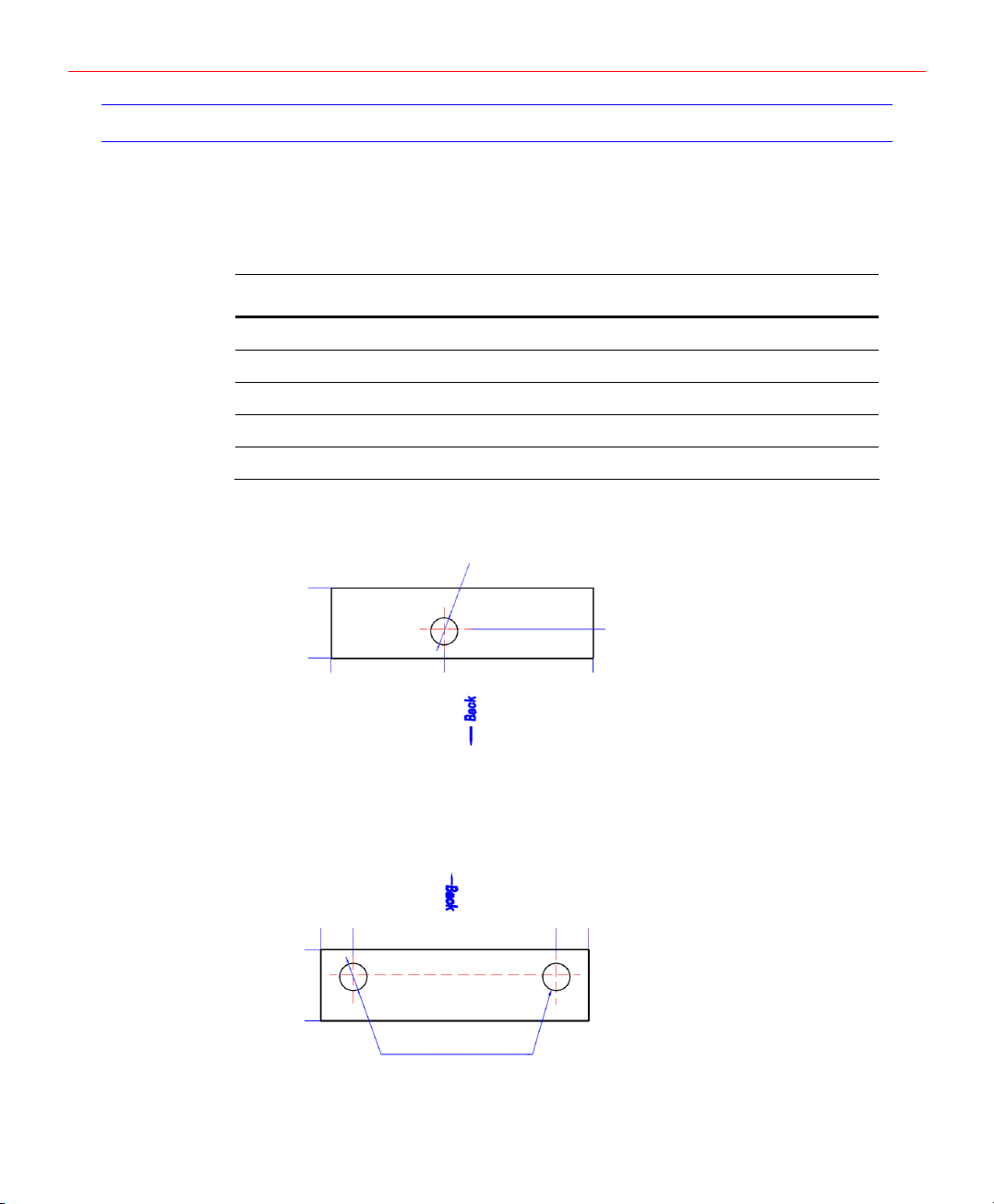
Mounting
The following five figures show the back, top, bottom, right, and left views of the IP-AK2
panel cabinet. Each view includes the dimensions and knockout placement to mount the
cabinet. See the table below for dimensions of the conduit entries into the cabinet.
Table 3-1 Cabinet Electrical Entries
ENCLOSURE CONDUIT 1” (30mm) CONDUIT 2” (40mm)
Top 2 N/A
Bottom N/A 1
Right 2 N/A
Left 2 N/A
Back 1 N/A
Figure 3-1 IP-AK2 Panel Cabinet - Top View
78mm [3.071”]
φ30mm [φ1.181”] Diameter Knockout
0mm [0.000”]
0mm [0.000”]
125mm [4.921”]
Figure 3-2 IP-AK2 Panel Cabinet - Bottom View
0mm [0.000”]
0mm [0.000”]
78mm [3.071”]
35mm [1.378”]
φ30mm [φ1.181”] Diameter Knockout
255mm [10.039”]
32.44mm [1.277”]
290mm [11.417”]
290mm [11.417”]
6
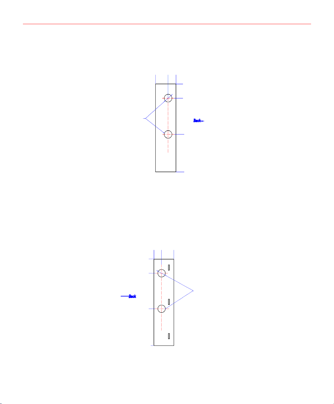
Figure 3-3 IP-AK2 Panel Cabinet - Left View
78mm [3.071”]
φ30mm [φ1.181”] Diameter Knockout
0mm [0.000”]
30mm [1.181”]
0mm [0.000”]
55mm [2.165”]
195mm [7.677”]
Honeywell
340mm [13.386”]
Figure 3-4 IP-AK2 Panel Cabinet - Right View
30mm [1.181”]
0mm [0.000”]
55mm [2.165”]
195mm [7.677”]
340mm [13.386”]
0mm [0.000”]
78mm [3.071”]
φ30mm [φ1.181”] Diameter Knockout
7
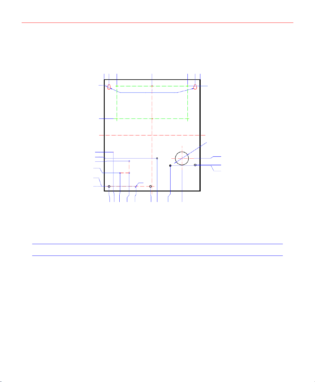
Installation
Figure 3-5 IP-AK2 Panel Cabinet - Back View
0mm [0.000”]
18mm [0.709”]
119mm [4.685”]
221mm [8.701”]
240mm [9.449”]
248mm [9.764”]
284mm [11.181”]
324.5mm [12.776”]
325mm [12.795”]
15mm [0.591”]
38.25mm [1.506”]
φ10mm [φ0.394”] Diameter (2 holes)
2-N3
144.92mm [5.706”]
290mm [11.417”]
251.75mm [9.911”]
275mm [10.827”]
20mm [0.787”]
φ40mm [φ1.575”] Diameter Knockout
240mm [9.449”]
260mm [10.236”]
262mm [10.315”]
Wirings
This section describes how to wire the IP-AK2 panel cabinet, the reader, the supervised
input and output.
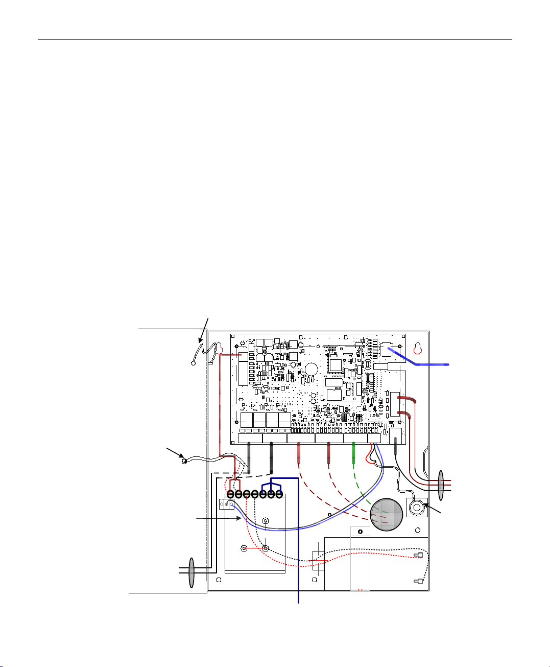
Cabinet Wiring
The picture below shows how to connect the IP-AK2 panel and the inputs, outputs,
power supply in cabinet.
8
15mm [0.591”]
76mm [2.992”]
28mm [1.102”]
48mm [1.890”]
140mm [5.512”]
97.1mm [3.823”]
160mm [6.299”]
200mm [7.874”]
235.06mm [9.254”]
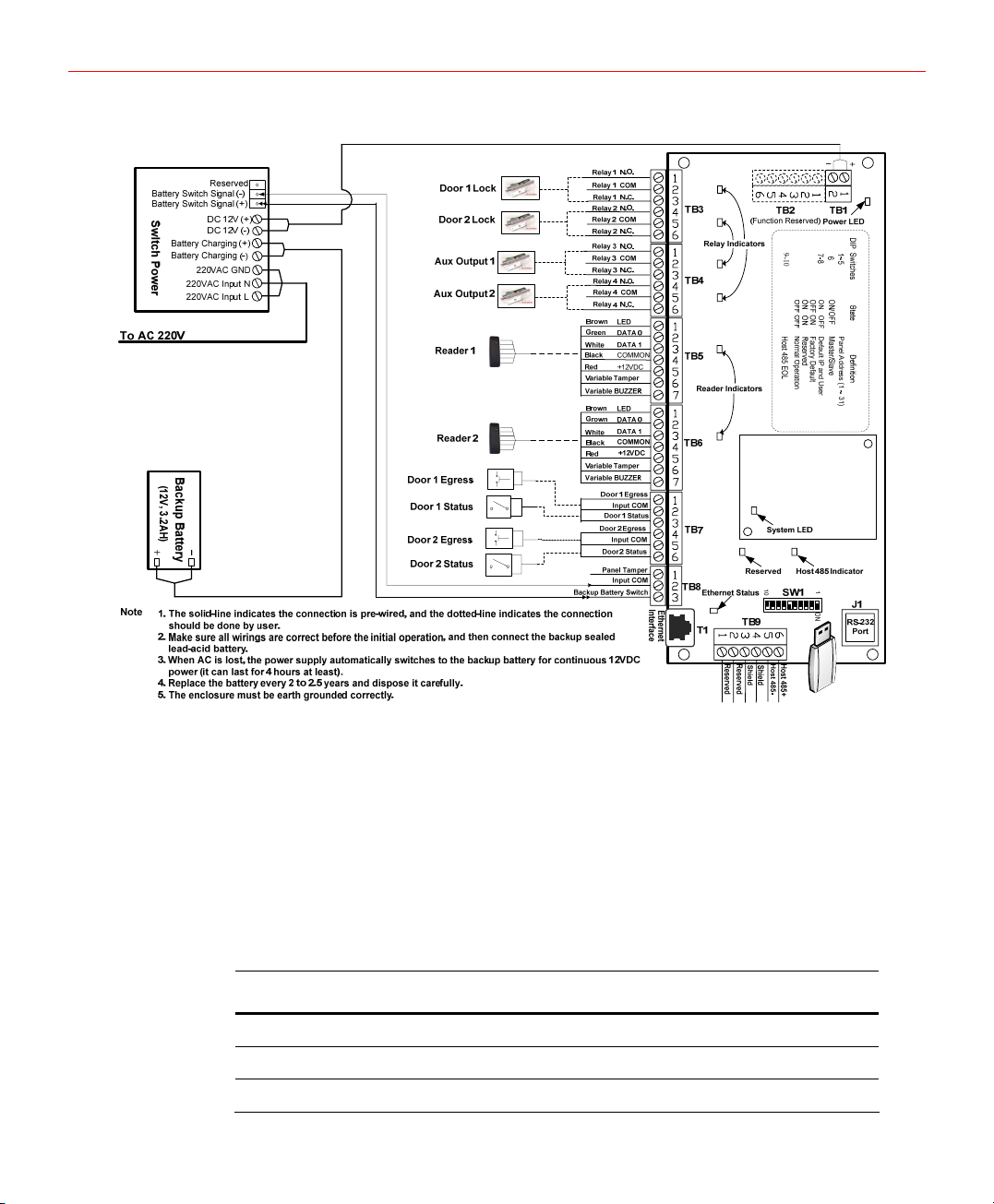
Figure 3-6 Cabinet Wiring
Honeywell
Reader Wiring
Each reader port supports a single 12-volt reader with Wiegand output format. The
maximum power draw is 300 mA for readers.
To fully utilize each reader port, a shielded 7-conductor cable (18-22 AWG) is required. If
the optional reader buzzer feature is not needed, you can use the standard 6-conductor
cable. The cable shield should be grounded at the panel only. Grounding at both ends
can cause ground loops which can be disruptive. The maximum recommended length of
wiring is 500 feet per reader.
Table 3-2 Reader Wiring
Terminal Wire Color Wiegand Reader
TB5-1, 6-1 Brown LED Control
TB5-2, 6-2 Green Wiegand Data 0 or Data
TB5-3, 6-3 White Wiegand Data 1 Or Clock
9

Installation
Terminal Wire Color Wiegand Reader
TB5-4, 6-4 Black Common
TB5-5, 6-5 Red 12VDC Power
TB5-6, 6-6 Variable Tamper
TB5-7, 6-7 Variable Buzzer
Supervised Input Wiring
The supervised inputs are located on TB5, TB6, TB7 and TB8. Input 1 through Input 4
may be configured for normally open or normally closed contacts as supervised or nonsupervised. Inputs 5 and 6 are on TB8.
Table 3-3 Default Supervised Input Assignments
Terminal Position Input Number Default Function
TB7-1 Input 1 Door 1 REX (Egress)
TB7-3 Input 2 Door 1 Status
TB7-4 Input 3 Door 2 REX (Egress)
TB7-6 Input 4 Door 2 Status
TB8-1 Input 5 Panel Tamper
TB8-3 Input 6 External Power Supply AC FAIL
TB 5-6, 6-6 Input 7/8 Reader Tamper
Figure 3-7 Typical Supervised Input Wiring Diagram
The figure above shows the typical wiring for a supervised input using standard 2,200
ohm resistors. The IP-AK2 panel accepts 1,000, 2,200, 4,700, or 10,000 ohm values.
Note that both resistors must have the same value.
In addition, the Panel Tamper and External Power Fail can be supervised and capable of
being used as additional inputs if the default functionality is not needed. They also share
a single common.
Caution
Supervised input wiring must be used if Input 6 is used for “External Power
Supply AC Failed”.
10

Honeywell
The wire used for the inputs should be shielded and cannot exceed 20 ohms over the
entire length of the cable. Remember that the distance from the panel to the door must
be doubled to determine the total resistance.
Caution
The cable shield should be grounded only at the panel. Grounding at both ends
can cause ground loops disruptive.
Output Wiring
Relay 1 is defaulted for controlling Door 1 lock, Relay 2 is defaulted for controlling Door 2
lock, Relay 3 and Relay 4 are used as auxiliary outputs.
IP-AK2 panel is connected to the nominal 12VDC power supply and cannot be used to
power the access control door strikes/locks or other auxiliary loads. The voltage range of
the relay outputs is 12VDC to 28VDC.
Each relay also has a green indicator LED, which indicates the relay state. If the relay is
triggered, the LED will be on.
Caution
The cable used must be sized for the current load and should be shielded. Do
not bundle these wires with communication, reader, or supervised input wiring.
DIP Switch Settings
IP-AK2 panel includes 10 DIP switches. The table below shows DIP Switch Definition.
Table 3-4 DIP Switch Definition
DIP Switches State Definition
1-5 Panel Address (1 ~ 31)
6 ON/OFF Master/Slave
ON OFF Default IP and User
7-8
9-10 Host 485 EOL
OFF ON Factory Default
ON ON Reserved
OFF OFF Normal Operation
Position 1 to position 5, whose panel address from 1 to 31; they are must not been set 0,
which is invalid.
Position 6 will be set with the Host RS485 Master & Slave mode. For Multidrop RS-485
line, Position 6 MUST be set “ON” for RS-485 gateway in Master mode.
Position 7 and position 8 have four combinations. When both of them are “OFF”, it
means normal operation; When position 7 is “ON” and position 8 is “OFF”, it means the
11
 Loading...