

Honeywell E529, INNCOM X47 4G Wiring Manual

7 March 2018
CONFIDENTIAL
INNtool Support Material: Wiring Line Voltage
E529/X47 4G Lin e V oltage Wiring
Disclaimer
This document contains information that is the proprietary and confidential property of INNCOM by Honeywell. By acceptance hereof, each
recipient agrees to use the inf ormation contained herein only for the purpose anticipated by INNCOM by Honeywell, and not to disclose to
others, copy or reproduce, any part hereof without the written consent of INNCOM by Honeywell. The recipient agrees to ret urn t his document to
INNCOM by Honeywell immediately upon request.
• DISCONNECT POWER BEFORE BEGINNING INSTALLATION. ELECTRICAL HAZARD: Can cause electrical shock or equipment damage.
• Must be installed by a trained , experienced technician.
• See device specific product guides for load specifications.
Table of Contents
1. WIRING GUIDE LINE VOLTAGE POWER SUPPLY (“B1” OPTION) ..................................................................... 2
2. THERMOSTAT WIRE CONNECTIONS: ............................................................................................................... 3
3. SYSTEM SPECIFIC WIRING GUIDES ................................................................................................................ 4
4. LOW VOLTAGE WIRING .................................................................................................................................. 6
5. FIELD SIDE WIRI NG ....................................................................................................................................... 7
6. DOCUMENT INFORMATION ............................................................................................................................. 8
22 November 2013
CONFIDENTIAL
Training Bulletin 01
Document or product name here
22 November 2013
CONFIDENTIAL
Training Bulletin 01
Document or product name here
22 November 2013
CONFIDENTIAL
Training Bulletin 01
Document or product name here
H
4
S5
123
H5
S5
123
ICP
PC502.1
Layer x
IOMAP 0
Add 227
123
Must not be mounted
inside metal enclosure!
2
1
3
2
1
3
4
5
FC11
FC12
FC13
FC14
FC15
ORG - S5
GRN - IN2
YEL - IN1
RED - DC OUT
BRN - COMMON
X47
FC2
FC1
FC9
FC8
FC7
FC6
FC5
FC4
FC3
FC10
GND
1
2
3
ANG OUT-1
ANG OUT-2
FC22
FC23
FC24
N/C
FC21
1
2
3
1
2
3
FC20
GND
FC19
10k NTC
N/C
FC18
FC17
GND
FC16
10k NTC
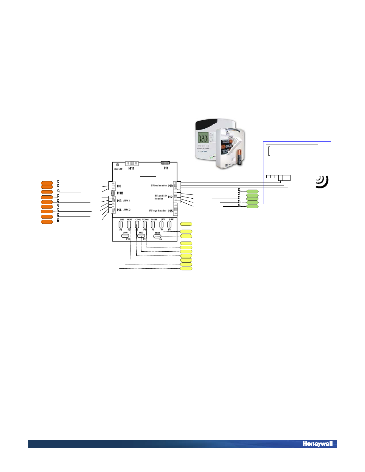
1. Wiring Guide Line Voltage Power Supply (“B1” option)
See detailed wiring guides for specific system types on the following page.
© INNCOM by Honeywell - 2 -
22 November 2013
CONFIDENTIAL
Training Bulletin 01
Document or product name here
22 November 2013
CONFIDENTIAL
Training Bulletin 01
Document or product name here
22 November 2013
CONFIDENTIAL
Training Bulletin 01
Document or product name here
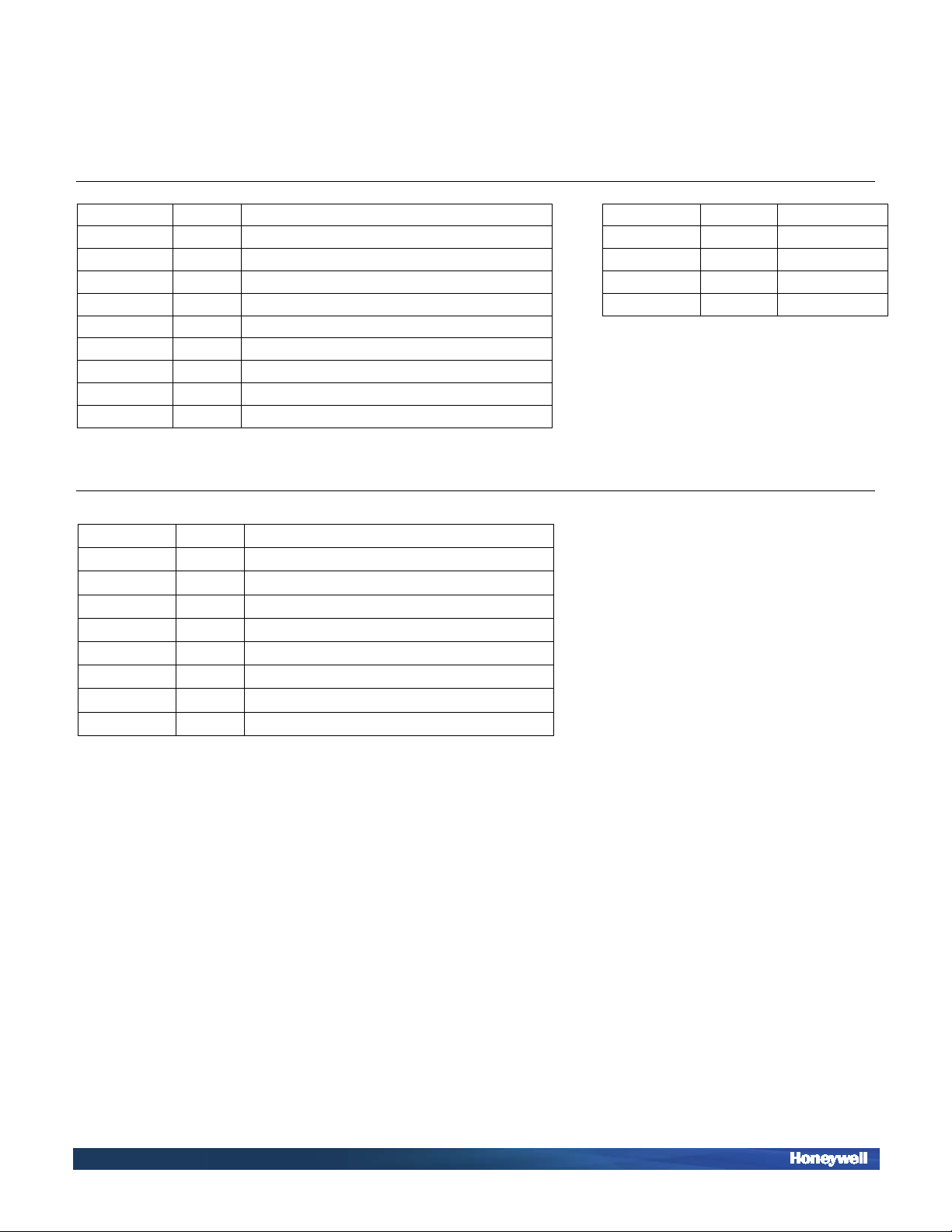
Connection
Color
Function
Connection
Color
Function
FC1
Green
EARTH GROUND
FC11
Brown
DC GROUND
FC2
Black
LINE
FC12
Red
DC OUT
FC3
White
NEUTRAL
FC13
Orange
S5 BUS
FC4
Yellow
HIGH FAN RELAY
FC14
Yellow
INPUT 1
FC5
Orange
MED FAN RELAY/ HEAT RELAY(STAGE 2)
FC15
Green
INPUT 2
FC6
Red
COMPRESSOR CONTACTOR
FC7
Brown
HEAT RELAY(STAGE 1)/ REVERSING VALVE
FC8
Grey
VALVE POWER
FC9
Violet
FAN POWER
FC10
Blue
LOW FAN RELAY
Connection
Color
Function
FC16
Orange
10K NTC (REMOTE THERMISTOR INPUT)
FC17
Red
GROUND
FC18
Brown
NO CONNECTION
FC19
Orange
10K NTC (REMOTE THERMISTOR INPUT)
FC20
Red
GROUND
FC21
Brown
NO CONNECTION
FC22
Orange
ANALOG OUTPUT-2
FC23
Red
ANALOG OUTPUT-1
FC24
Brown
GROUND
2. Thermostat wire conn ect ion s:
HVAC INTERFACE LOW VOLTAGE INTERFACE
FIELD SIDE INTERFACE
© INNCOM by Honeywell - 3 -
 Loading...