

Page 1

installation,
commissioning &
configuration
ID50/60
997-263-000-11, Issue 11 January 2010
manual
Page 2

ID50 Series Panel - Installation, Commissioning & Configuration Manual
Contents
1 Introduction 1
1.1 Manual Purpose 1
1.2 System Design and Planning 1
1.3 General 2
1.3.1 Date-dependent Functions 2
1.4 CE Marking 2
1.5 EN54 Functions 3
1.6 Ancillary Functions 4
1.7 Related Documents 5
1.8 Warnings and Cautions 5
1.9 Tips 5
1.10 Glossary of Icons 6
2 Installation Guide 7
2.1 How to Use this Section 7
2.2 Pre-Installation Check List 7
2.1.1 Some Panel DO’s and DON’T’s 7
2.3 Transient Protection 8
2.4 Product Inspection 9
2.4.1 Checking Your Panel for Damage 9
2.4.2 What to do if Panel is Damaged
or Suspect 10
2.5 Dismantling the Panel 11
2.5.1 Removing the Cover 11
2.5.2 Removing the Panel Electronics 12
2.5.3 Back Box Fixing 13
2.5.4 Semi-Flush Mounting Bezel (Optional)14
2.6 Assembling the Panel 15
2.7 RS485 Communications Link 16
2.7.1 Fitting the RS485 Interface Module PCB17
2.8 RS232 Interface Connections 18
Contents
3 Cabling 19
3.1 Cabling Instructions 19
3.1.1 Cable Terminations 20
3.2 Cabling Installation Notes 21
3.2.1 Introduction 21
3.2.2 Quality of Cable and of Cable Installation 21
3.3 EMC Considerations 22
i 997-263-000-11, Issue 11
January 2010
Page 3

ID50 Series Panel - Installation, Commissioning & Configuration Manual
3.3.1 Screen Termination 22
3.3.2 Ferrite Sleeves (Optional) 22
3.4 MICC Cables 22
4 Commissioning 23
4.1 Introduction 23
4.2 Preliminary Checks 23
4.3 Internal Checks 24
4.3.1 Jumper Link Options 24
4.4 External Wiring Checks 25
4.4.1 Loop Wiring 26
4.4.2 RS485 Communications Link 27
4.4.3 DC Auxiliary Output 27
4.4.4 Sounder Circuit Outputs 28
4.4.5 CFG Outputs C and D 30
4.4.6 -VE Outputs 31
Contents
4.4.7 Digital / ÜE Inputs 31
4.4.8 Switch Connections 31
4.5 Powering the Panel 32
4.5.1 Start-up Language Selection 32
4.5.2 Batteries 33
4.6 Configuration and Handover 34
4.7 Commissioning Tests 35
4.7.1 Test LEDs 35
4.7.2 Test LCD 35
4.7.3 Test Zones 35
4.7.4 Test Auto High Test 35
4.7.5 Test Outputs 35
4.7.6 Test Buzzer 35
4.7.7 Test Keyboard 35
4.8 Sensors and Modules 36
4.8.1 EN54 Requirements 36
4.8.2 Loop Wiring Testing 36
January 2010
5 Configuration 37
5.1 Introduction 37
5.2 Navigation and Number Entry 37
5.3 Level 2 Configuration Options 37
5.4 Level 3 Configuration Options 38
5.5 Setup Options 39
5.5.1 Panel Options 39
ii997-263-000-11, Issue 11
Page 4

ID50 Series Panel - Installation, Commissioning & Configuration Manual
5.5.2 Site Details 45
5.5.3 Device Options 46
5.5.4 Peripheral Options 53
5.5.5 Day/Night Settings 61
5.6 Circuit Options 67
5.6.1 Signalling Line Circuit (SLC) - Devices 67
5.6.2 Signalling Line Circuit (SLC) - Learn 77
5.6.3 On-Board Circuits 79
5.7 Control-By-Event Output Rules 81
5.7.1 Output Type 84
5.7.2 Filter-by-type 85
5.7.3 Evacuation 86
5.7.4 Silence 86
5.7.5 Interrupt Delay 87
5.7.6 Class Change 87
5.7.7 Two Zone 88
5.7.8 Zones 89
5.7.9 Device Inputs 90
5.7.10 Soak Timer 91
5.8 Zone Texts 91
5.9 Access Options 92
5.10 System Options 93
5.10.1 Crystal Frequency 94
5.10.2 Wipe Memory 95
5.11 Normal 95
Appendix 1 - Specification A1-1 to A1-6
Appendix 2 - ID60 Single Loop Panel
Differences A2-1 to A2-5
Appendix 3 - Fault Messages & Meanings A3-1 to A3-4
Appendix 4 - EN54-2 Options with
Requirements A4-1 to A4-4
Appendix 5 - Configuration of a Fault Routing
Output Using a Zone Monitor A5-1
Contents
iii 997-263-000-11, Issue 11
January 2010
Page 5

ID50 Series Panel - Installation, Commissioning & Configuration Manual
1 Introduction
1.1 Manual Purpose
The purpose of this manual is to provide the user with all
recommended procedures and full technical details for
the successful installation, commissioning and
programming of a NOTIFIER ID50 Series Panel.
The descriptions and procedures also apply to the
NOTIFIER ID60 panel. Differences between the ID50 and
ID60 panels are given in Appendix 2.
Procedures described in this manual include appropriate
warnings and cautions to guide the user towards adopting
safe and methodical work practices during the installation,
commissioning and programming phases.
The ID50 Series panels support OPAL protocol devices.
These devices support both OPAL and CLIP loop polling
protocols so they can be added to an existing CLIP
protocol loop. However, when OPAL protocol is enabled
on a loop a maximum of 10 CLIP device addresses can
be supported as part of the total of 99 sensors and 99
modules.
Important Note
This manual must be read, and its content clearly
understood, before proceeding with any work relating to
the ID50 Series Panel. Damage to the control panel may
result from NOT following the recommended procedures
described in this manual.
This manual provides all necessary instructions for the
ID50 Series Panel and applies only to fire panels fitted
with compatible software.
CAUTION: In particular, care must be taken when
powering up/down any repeaters.
If there are any areas of doubt, consult your supplier
before continuing with the system installation,
commissioning and programming.
1.2 System Design and Planning
It is assumed that the system, of which the ID50 Series
Panel equipment is a part, has been designed by a
competent fire alarm system designer in accordance with
the requirements of EN54 Part 14 and any other local
codes of practice that are applicable.
Introduction
The design drawings should clearly show the positions
of all the ID50 Series Panel control equipment and field
devices.
1
997-263-000-11, Issue 11
January 2010
Page 6
ID50 Series Panel - Installation, Commissioning & Configuration Manual
1.3 General
The ID50 Series Panel is designed for use with
NOTIFIER’s range of addressable analogue sensors,
control and monitoring modules and addressable call
points. A unique signalling protocol is used, having digital
address and control signals and analogue pulse width
monitoring for the reply data from devices.
The serial communications interface operates under
RS485 protocol and enables communications between
the fire panel and repeaters.
While every effort is made to ensure the accuracy of the
content of this manual, the manufacturer reserves the
right to change the information without notice.
Installation
Only suitably-qualified
engineers must install,
commission and
configure this product.
Only fit the electronics
module after all the other
trades have completed
their tasks!
The ID50 Series Panel is easy to install providing the
recommended procedures described in this manual are
followed. To avoid inadvertent contamination of the PCB
Assembly, the manufacturer recommends it be installed
in the back box only after all other trades have completed
their tasks.
Commissioning
To commission the ID50 Series Panel, follow the
recommended procedures described in this manual. The
manufacturer recommends that during commissioning
and maintenance, ALL RS485 signal cables are
disconnected at the Panel end, BEFORE powering down
the system and are connected AFTER powering up the
system.
Introduction
Configuration
To configure the panel and system, carefully read and
follow the procedures given in this manual. These
procedures describe the menus that are displayed on
the Liquid Crystal Display (LCD) Unit.
Refer to the ID50 Series Operating manual (ref: 997264-000-X) for a description of compatible addressable
Signalling Loop Circuit (SLC) analogue devices.
1.3.1 Date-dependent Functions
The calendar end date for this product is 31/12/2063
(two thousand and sixty-three) and it will perform correctly
up to this date.
The calendar function has not been tested beyond
this date.
1.4 CE Marking
CE
This panel is CE Marked to show that it conforms to the
requirements of the following European Community
Directives:
January 2010
2997-263-000-11, Issue 11
Page 7
ID50 Series Panel - Installation, Commissioning & Configuration Manual
The EMC Directive 2004/108/EEC, by the application of
the following EMC Standards:
EN 61000-6-3: Electromagnetic Compatibility (EMC)
Generic emission standard for Residential,
Commercial and Light industrial environments
EN 50130-4: EMC Product family standard: Immunity
requirements for components of fire, intruder and
social alarm systems.
Low Voltage Directive 2006/95/EEC, by the application
of the safety standard:.
EN 60950-1: Safety of information technology
equipment.
The Construction Products Directive 89/106/EEC, by the
application of the following standards:
EN 54-2:1998, (Amd. 1 & 2): Fire detection and fire
alarm systems - Control and indicating equipment.
EN 54-4: 1998 (Amd. 1 & 2): Fire detection and fire
alarm systems - Power supply equipment.
1.5 EN54 Functions
This fire control panel is designed to comply with the
requirements of EN 54 Part 2/4. In addition to the basic
requirements of EN 54-2, the panel may be configured to
conform with the following optional functions - the applicable
clauses of EN 54-2 are referenced as follows:
Options Clause
Indications:
Fault signal from fire protection equipment 7.10.4
Recording of the number of entries
into fire alarm condition 7.13
Fault signals from points 8.3
Controls:
Delay to Outputs 7.11.1
Manual or automatic switching of delays to outputs 7.11.2
Dependency on more than one alarm signal, Type B 7.12.2
Disablement of each address point 9.5
Test condition 10
Outputs:
Fire alarm device(s) 7.8
Fire alarm routing equipment 7.9.1
Fire alarm routing equipment with alarm confimation 7.9.2
Automatic fire protection equipment: Type A 7.10.1
Automatic fire protection equipment: Type C 7.10.3
Fault warning routing equipment 8.9
Introduction
3
997-263-000-11, Issue 11
January 2010
Page 8
ID50 Series Panel - Installation, Commissioning & Configuration Manual
EN
12094-1
!
The following features are provided by the Power Supply
Unit (PSU) of the ID50 Series Panel to comply with EN 54-4.
Features of the ID50 EN54-4
Power Supply Unit (PSU) Clause
Derive power supply from main power source 5.1
Derive power supply from and monitor a
standby battery source 5.2
Charge and monitor the standby
battery source 5.3
Detect and signal PSU faults 5.4
1.6 Ancillary Functions
The following is a list of ancillary functions that are
provided by the ID50 Series panel in addition to the those
required by EN54-2/4. These functions are described in
the section of this manual as referenced (except those
marked thus ‘*’ which are described in 997-264-000-X,
ID50 Series Panel - Operating Manual):
Introduction
Ancillary Manual
Functions Section Refs.
Site Specific Setup Options 5.5
Access Options 5.9
Voltage Indications *4.12
Control-by-Event 5.7
Output modes 5.7.1
Input type pattern 5.7.9
Disable/enablement *4.9
Repeater interface 2.7
Self-learn configuration - manual 5.6.1
Self-learn configuration - auto 5.6.2
Module supervision options 5.6.1
Module silence options 5.7.4
Text editing 5.8
Sensor LED blinking on/off 5.5.3.4
CAUTION:
12094-1
!
with EN 12094-1.
This product is not compliant
EN
Fire extinguishing installations in
Europe are required to be certified as
compliant to this standard.
January 2010
Bell pulsing ratio 5.5.3.5
Display of alarm count *4.11.6
Extend delay timer 5.5.5.3
Sounder Volt-free contact options 4.4.5
Relay drive output option 4.4.6
Extinguishing system features 5.5.3.7, 5.5.3.8, 5.5.3.9,
5.7.1, 5.7.2, 5.7.10
4997-263-000-11, Issue 11
Page 9
ID50 Series Panel - Installation, Commissioning & Configuration Manual
1.7 Related Documents
This manual only describes the installation,
commissioning and configuration of the ID50 Series
Panel. All operating functions are covered by the:
ID50 Series Panel Operating Manual (ref:
997-264-000-X)
The Panel can support repeaters via the RS485
communications link. This manual does not provide
details about the repeaters or Compact Mimics; these
are described in:
IDR-2A, -2P & -6A Repeaters User Manual
(ref: 997-411-000-X).
IDR Mimic Installation and Commissioning Manual
(ref: 997-412-000-X).
Compact Mimic Installation Instructions (ref. 997-497-
000-X).
Note: The ‘000’ part of the manual reference is the UK
country code for the manual.
WARNING: High Voltage!
Take suitable precautions to
avoid electric shock
EN54-2:-8.8
One hardware-
configurable output
must be configured
as a fault relay
The ID50 Panel can also support the VIEWTM sensor. This
manual does not attempt to cover all the VIEWTM sensor
programming and calibration issues as these are
described in some detail in the following, which is available
from NOTIFIER’s Technical Support Department:
VIEW
TM
Application Guide (ref: 997-198).
1.8 Warnings and Cautions
Where appropriate, the manual includes advisory
warnings and cautions to remind you to consider safety
at all times, especially when following the procedures
described herein.
You are alerted to any areas where high voltage [i.e. nonSafety Extra-Low Voltage (SELV)] is present, or where
there may be a risk of damage to static-sensitive devices
if the recommended procedures described in this manual
are not followed.
An example of a high voltage warning and an anti-static
caution is provided to the left of this paragraph.
The ID50 Series Panel incorporates some features
which, if used inappropriately, may contravene the
requirements of EN 54. Where there is a possibility of
such an occurrence, a suitable warning is given with brief
details of the EN 54 requirement. A typical EN 54 noncompliance warning is illustrated at left.
Introduction
Magnetise the tip of your
screwdriver to help when
offering small screws to
holes in confined spaces.
1.9 Tips
‘Handy tips’ are included, where appropriate, to assist
you in following quick and safe procedures for fire
detection system installation and integration.
Look for the ‘TIP!’ icon and supporting text, typically
illustrated at left.
5
997-263-000-11, Issue 11
January 2010
Page 10
ID50 Series Panel - Installation, Commissioning & Configuration Manual
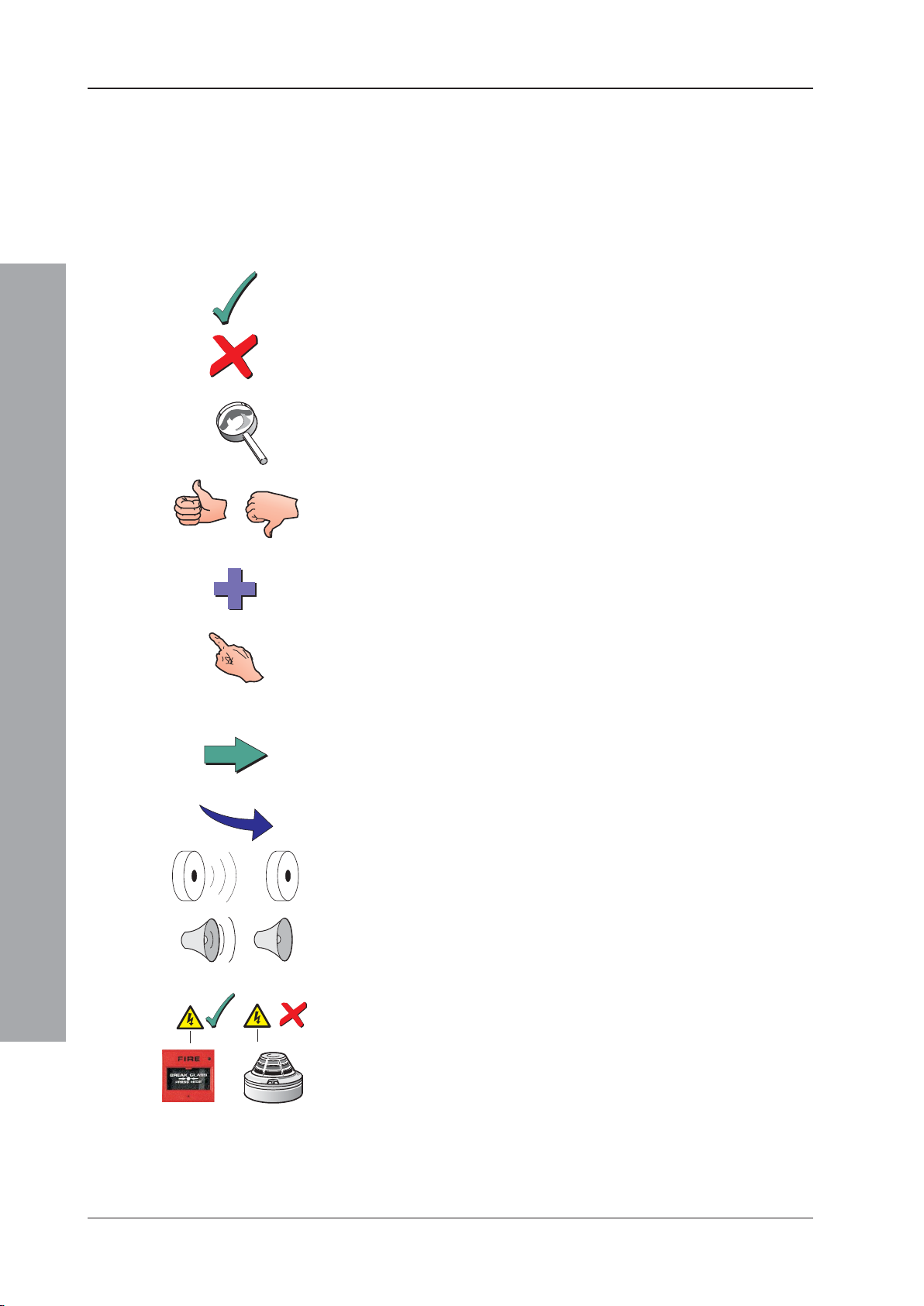
1.10 Glossary of Icons
Throughout this manual, and the other related ID50
Series Panel manuals, a number of icons are used either
as part of the illustrated process descriptions, or in the
main text to help clarify, or simplify, particular
configuration procedures.
The following icons are used to advise or indicate:
a. DO follow the recommended procedure or method.
b. DO NOT use this procedure or method.
c. Inspection of an item or sub-assembly is required at
this point.
d. Following a defined process meets/ does not meet
the required approval/inspection criteria or standards.
Introduction
e. Additional items to be considered.
f. This icon placed next to a pushbutton requires you to
press it while configuring the panel. Where two or
more icons are used, a number may be placed on or
near each hand to indicate the order of selection: 1
coming before 2.
g. Activity process step - flow arrow for single action or
iterative actions.
h. Leader arrow - used with activity processes.
i. Internal buzzer operating/not-operating or silenced.
j. Sounder operating/not-operating or silenced.
k. Power connected and switched ON/disconnected and
switched OFF.
January 2010
l. Manual Call Point (MCP)/Sensor.
6997-263-000-11, Issue 11
Page 11
ID50 Series Panel - Installation, Commissioning & Configuration Manual
2 Installation Guide
2.1 How to Use this Section
This Installation Guide provides guidelines on how to
install an ID50 Series Panel quickly and safely.
For each stage in the panel installation and
commissioning procedures a brief description is given of
its purpose, complete with detail drawings, flow diagrams
and/or other graphics to make the instructions easy to
follow. Where required, procedures may be broken down
into one or more related diagrams, the number being
dependent upon the complexity of the defined task.
2.2 Pre-installation Check List
Before installing the ID50 Series Panel or fitting sensors,
you must first ensure that the following criteria have been
met. Failure to do this may not only result in damage to
the equipment, but may also cause problems when
commissioning the equipment or adversely affect its
performance.
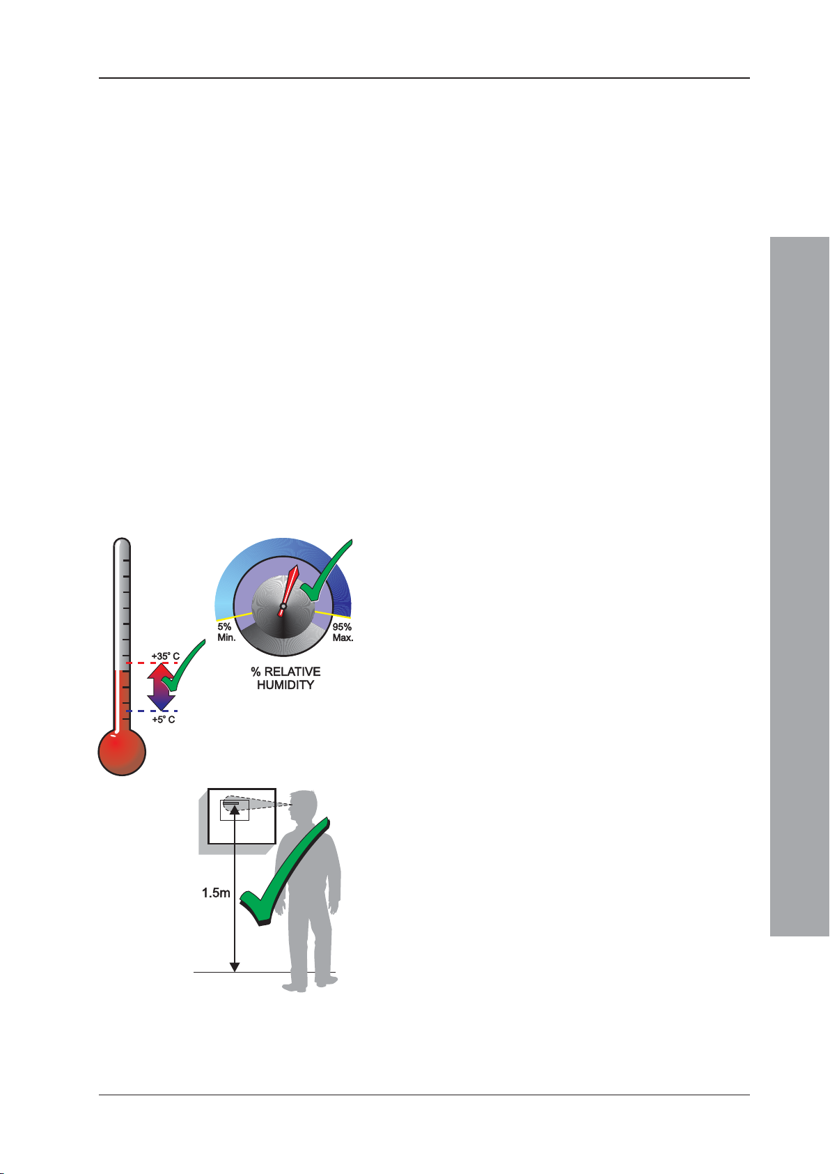
2.2.1 Some Panel DO’s and DON’T’s
Before selecting a location for the ID50 Series Panel,
DO make sure that:
a. The operating ambient temperature is in the
recommended range:
+5oC to +35oC and
b. The relative humidity is between:
5% and 95%
c. The panel is wall mounted in a position which allows
clear visibility of displays and easy access to operating
controls. The height above floor level should be
chosen such that the LCD is just above normal eye
level (approximately 1.5 metres).
Installation Guide
7 997-263-000-11, Issue 11
January 2010
Page 12

ID50 Series Panel - Installation, Commissioning & Configuration Manual
d. DO NOT locate the panel where it is exposed to high
levels of moisture.
e. DO NOT locate the panel where there are high levels
of vibration or shock.
f. DO NOT site the panel where there would be restricted
access to the internal equipment and cabling/wiring
connections.
Installation Guide
2.3 Transient Protection
This equipment contains transient-protection devices.
Although no system is completely immune from lightning
transients and interference, for these devices to function
correctly, and to reduce susceptibility, this equipment
must be earthed correctly.
As with all solid state devices, this system may operate
erratically or can be damaged if subjected to lightninginduced transients.
The use of overhead or outside aerial wiring is not
recommended due to the increased susceptibility to
nearby lightning strikes.
January 2010
8997-263-000-11, Issue 11
Page 13
ID50 Series Panel - Installation, Commissioning & Configuration Manual
2.4 Product Inspection
The ID50 Series Fire Control Panels are relatively simple
to install providing the recommended procedures
described in this Installation Guide are followed.
To avoid damage to the
control panel ensure that
you follow these
instructions.
Follow all installation instructions described in this
manual. These instructions must be understood and
the manufacturer’s recommendations followed to
avoid damage to the control panel and associated
equipment.
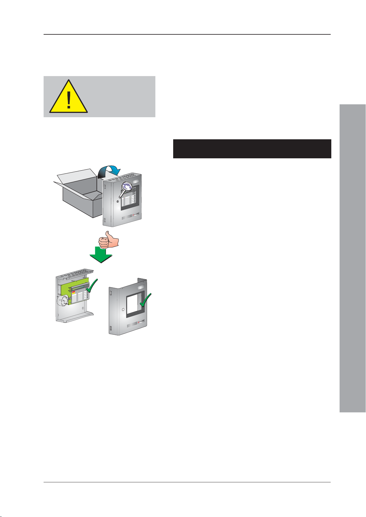
2.4.1 Checking Your Panel for Damage
It is important to check all supplied equipment for
damage before proceeding with the installation!
1
2
Before attempting to install your ID50 Series Panel, you
should do the following:
1 After removing the panel, from its packing, and before
you proceed with installing it in its chosen location,
check for any damage that may have been caused
during transit.
Note: In the unlikely event that the panel supplied has
been damaged, you MUST NOT install it but return
it to your supplier. The procedure for returning faulty
items is described in Section 2.4.2, What to do if
Your Panel is Damaged or Suspect.
2 If you are satisfied that the panel has NOT been
damaged you can now proceed with the installation
procedure. This manual addresses the recommended
installation methods of the panel. Refer to the relevant
sections that apply to your configuration requirements.
To prevent unnecessary damage to the electronic
components, the back box should be installed without
the electronics fitted. Refer to Sections 2.5.1 to 2.5.3
for details.
Installation Guide
9 997-263-000-11, Issue 11
January 2010
Page 14
ID50 Series Panel - Installation, Commissioning & Configuration Manual
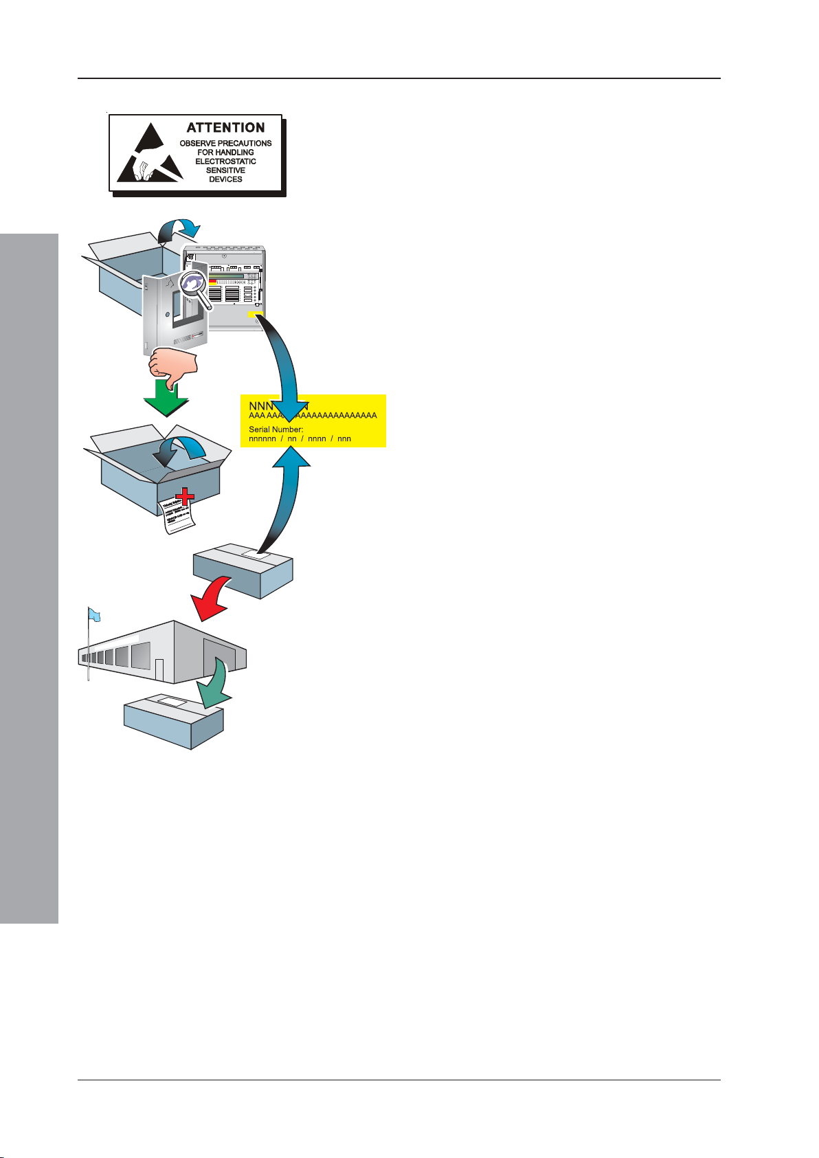
2.4.2What to do if Panel is Damaged or Suspect
If you have problems regarding the quality of any supplied
order items including the control panel, its ancillaries or
this manual or items are missing, follow the procedure
below:
1
2
3
1 DO NOT continue with the installation but contact your
supplier for advice on what to do next.
Similarly, if the product is found to be faulty during
installation or while in use contact your supplier
immediately.
2 To aid your supplier and the manufacturer, you are
requested to:
a. Quote the manufacturer’s unique batch reference
number which can be found on the packaging or
inside the back box.
b. With reference to PCB’s, quote the part number
and revision level which can be found along one
edge of the PCB - refer to the applicable section
of this manual for specific details.
c. Note all the details relevant to your complaint, date
of receipt, packaging condition, etc. and forward
this to your supplier.
3 Where the product needs to be returned to your
supplier, you are requested to use the original
packaging, or suitable anti-static equivalent,
wherever possible.
Installation Guide
January 2010
10997-263-000-11, Issue 11
Page 15
ID50 Series Panel - Installation, Commissioning & Configuration Manual
1
2
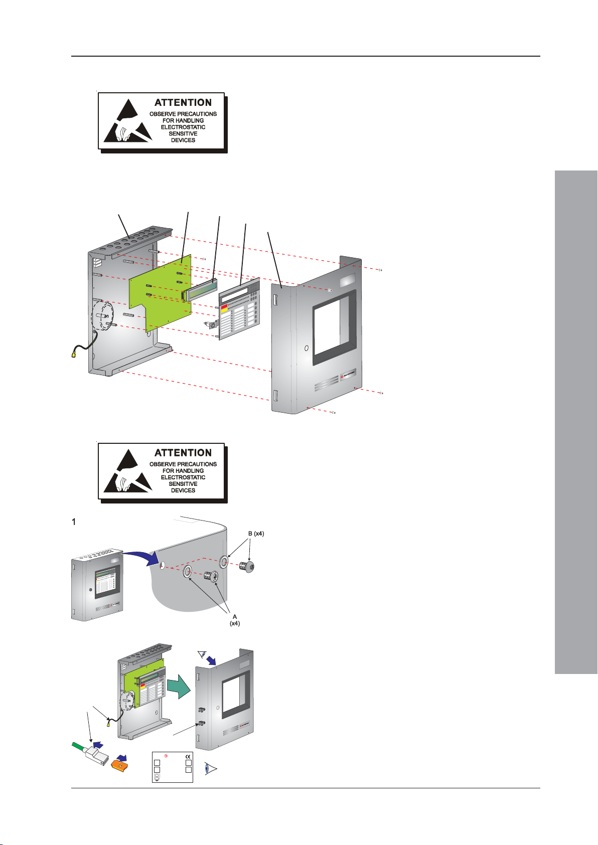
2.5 Dismantling the Panel
For installation purposes, it is recommended that the
cover is removed from the back box and stored in a safe
place until ready for commissioning.
If any other trades, e.g. plasterers or decorators, will be
working in the vicinity after fitting the ID50 Series Panel,
it is strongly recommended that before re-fitting the cover
you remove the panel electronics and store in a safe place
until ready for commissioning. The main components
A
B
C
D
within the ID50 Series Panel are shown below.
E
ID50 Series Panel Assembly
A. Back box
B. PCB Assembly
C. LCD Unit
D. Fascia & Control Keypad
E. Cover
2.5.1 Removing the Cover
To remove the ID50 Series Panel cover, it is
recommended that the following procedure is carried out
on a work bench BEFORE siting the panel on the wall:
1 Remove the four M3 x 6mm screws and washers (A)
using a No. 1 Posidriv screwdriver, or the four hex
button-headed screws and clear washers (B) using a
2mm hex key, from the cover, and store safely.
2 Carefully withdraw the cover away from the back box,
until the earth blade terminal (C) within the cover is
accessible.
3 Carefully detach the shrouded earth lead spade
terminal (D) from the earth blade terminal (C) located
in the left-hand inner side wall of the cover.
2
E
Note: All blade connections to earth incorporate a locking
barb. To make a connection push the shrouded
receptacle on to the earth blade (1). To remove
2
3
D
this connection, pull the shroud (2), NOT the earth
wire.
4 Remove and store the cover in a safe place.
Installation Guide
3
C
NOTIFIER
byHoneywell
ID50
ID60
NF50-A
NF30-A
230VAC, 50Hz, 1.0A
‘E’
The power supply ratings label (view ‘E’) is affixed to the
inside face of the fire control panel cover.
Before installing the back box, remove the panel
electronics (see Section 2.5.2, Panel Electronics).
11 997-263-000-11, Issue 11
January 2010
Page 16
ID50 Series Panel - Installation, Commissioning & Configuration Manual
6
A
1
B
394-191
issue
XXX
TB3
J19
1
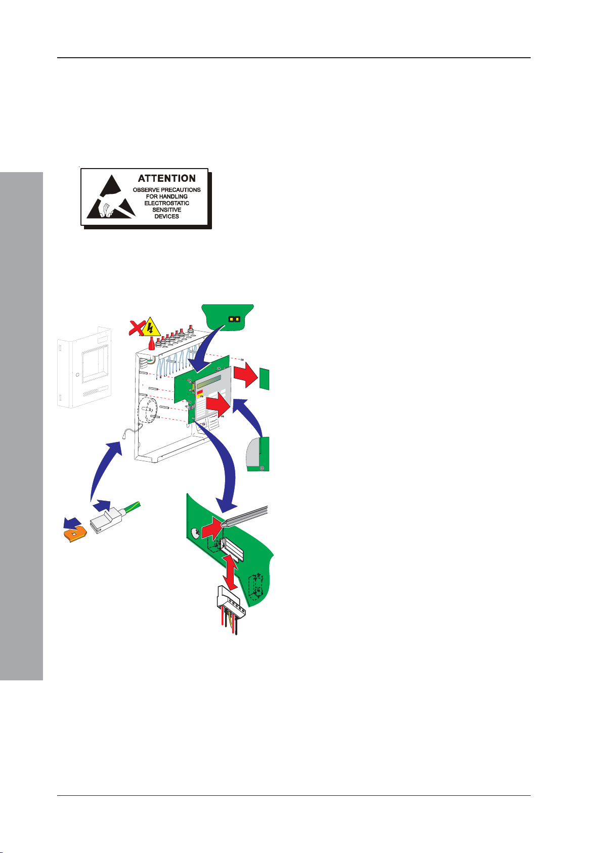
2.5.2 Removing the Panel Electronics
The ID50 Series Panel electronics comprises the PCB
assembly with mounted LCD unit and the mounted fascia.
These are supplied as one spared item in kit
PN: 020-635-XXX. This assembly is located within the
back box, but should ONLY be removed when installing
the back box or if the PCB requires replacement.
CAUTION: The electronic circuits of the ID50 Series
Panel use CMOS devices which can be damaged by
static discharge. Suitable precautions MUST be taken
when handling circuit boards.
Procedure
When installing the back box or, if it becomes necessary
to remove the PCB assembly for another reason, follow
this recommended procedure:
1 Remove the cover and store in a safe place, see
Section 2.5.1, Removing the Cover. Then make a
back-up of the current system configuration,
remembering to disconnect the link at jumper J19.
Installation Guide
Note: The blade connection to the cover fitted in back
4
boxes incorporates a locking barb. To remove this
connection, pull the shroud (B), NOT the earth wire,
6
from the earth blade terminal (A).
2 Isolate the mains power supply and disconnect the
battery interlink wire if fitted.
3 At the two-part connector TB1 (on the PCB assembly),
4i
ue XXX
using a constant pulling action carefully disconnect
394-191 iss
the mains and battery power supply wiring.
4 Taking suitable anti-static precautions remove the
RS485 Interface PCB, if fitted (refer to Section 2.7.1,
Installing the RS485 Interface Module PCB).
5 At the PCB assembly, note the polarity and
connections of all cables and any jumper configuration
settings. Using a screwdriver, loosen all the connector
securing screws. Carefully secure all external cable
3
tails away from the electronics and from the back box.
6 Using a No. 1 Posidriv screwdriver, remove the eight
(8) M3 x 8mm clinch screws from the PCB assembly.
Gently lift the PCB assembly clear of the supporting
pillars, place it in an anti-static bag and store safely.
Note: If the PCB is to be returned to the manufacturer
note its Serial Number and Revision Level (located
along one edge).
12997-263-000-11, Issue 11
January 2010
Page 17
ID50 Series Panel - Installation, Commissioning & Configuration Manual
376.00
301.00
365.00
37.50
188.00
45.00
275.00
45.00
All dimensions are in millimetres. Fixing
hole diameters are 6mm.
DO NOT use the back
box as a guide when
drilling
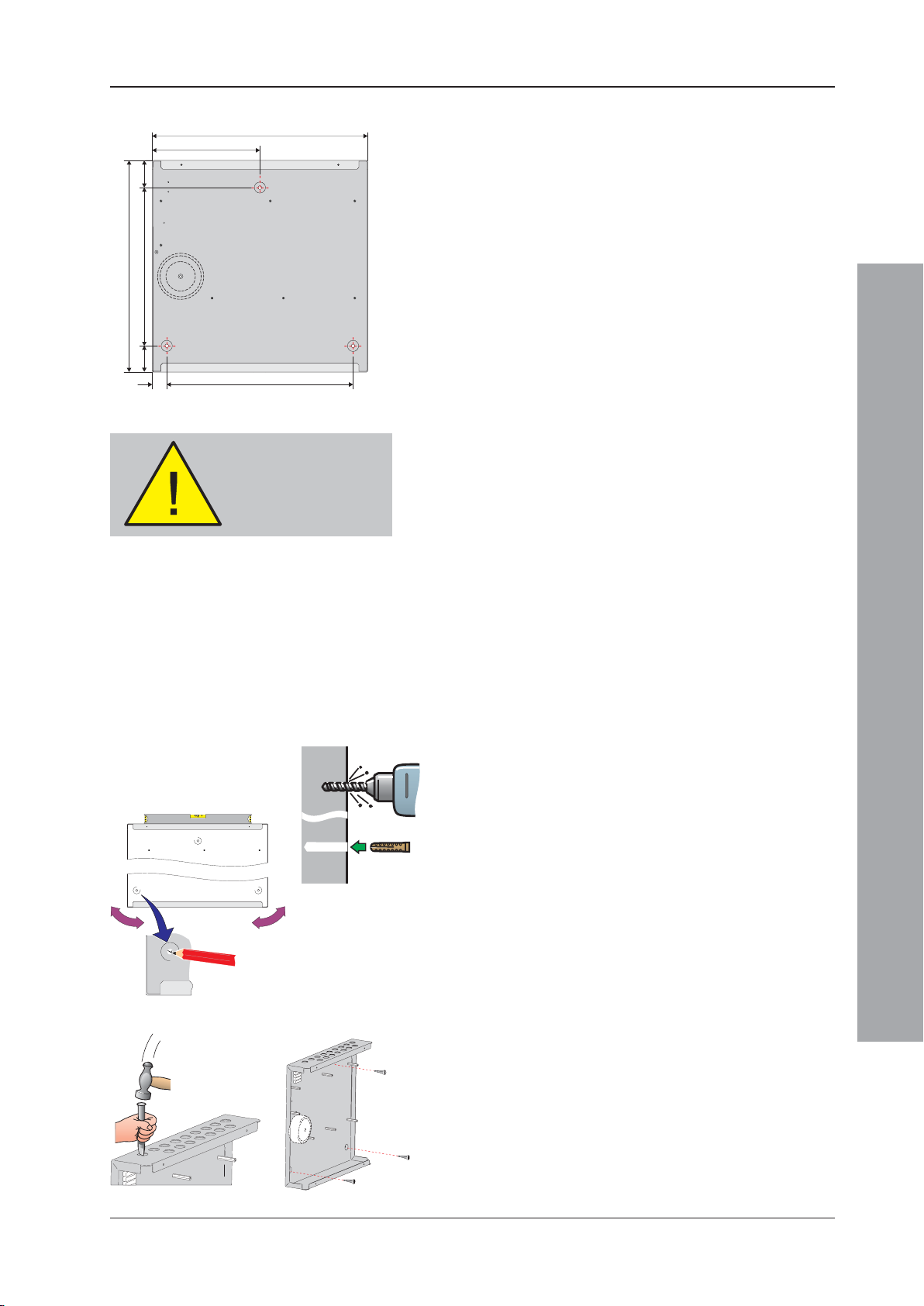
2.5.3 Back Box Fixing
The ID50 Series Panels (PN: 002-455-XXX) are 110mm
deep (external dimensions including fixing dimples). The
back box holds two 12V batteries, up to a maximum rating
of 12Ah each.
The back box must be fixed to the wall with screws at
three fixing locations (see drawing) using the procedure
given below.
The back box must only be installed when the panel
electronics have been removed (see Section 2.5.2,
Removing the Panel Electronics).
Wall Flatness
To prevent distortion, the back box MUST be installed on
the wall as flat as possible, i.e. with a maximum flatness
deviation between any two points of 3mm. Where the
wall is out of tolerance, use appropriate packing pieces
when installing the back box to meet the above
requirements.
Failure to comply with this requirement will result in
the misalignment of the cover’s securing screws,
which may cause difficulties in fitting the cover.
Procedure
When a suitable location has been found for installing
the panel and the panel electronics have been removed,
fix the back box to the wall as follows:
1 Using a suitable-sized drilling bit - for holes to take up
1, 3
to 6mm (No. 12-sized) wood screws - drill a hole at
position A in the wall. Fit a suitable-sized Rawl-plug,
or equivalent.
2
A
B
B
2 Hold the back box in position at hole A (ensure the
panel is level) and mark the position of the remaining
fixing holes (B). Remove the back box and store safely.
3 Drill two holes at positions B in the wall, and fit suitable-
sized Rawl-plugs, or equivalent.
Installation Guide
4 Prepare apertures (20mm knockouts) required for
cable access.
Note: Make sure paint is scraped from the area
surrounding the knockouts, to ensure good
earthing for glands.
4
5
5 Secure the back box to the wall using all three fixing
holes and appropriate-sized screws (up to 6mm
[No. 12-sized] round or pan-head screws - do not use
countersunk screws).
13 997-263-000-11, Issue 11
January 2010
Page 18
ID50 Series Panel - Installation, Commissioning & Configuration Manual
367
437
383
453
329
375
D
B
C
2
5
2
WALL
RECESS
E (x4)
3
3
A
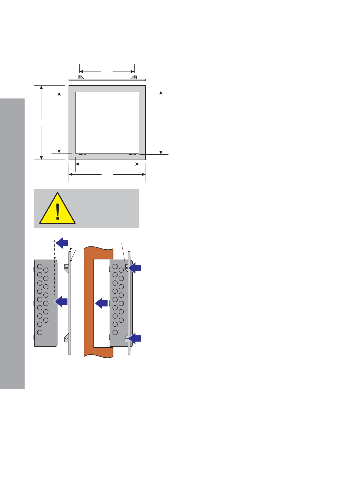
2.5.4 Semi-Flush Mounting Bezel (Optional)
If semi-flush mounting of the ID50 Series Panel is
required, a recess 80mm deep and just large enough to
accommodate the back box must be cut in the wall (see
dimensions below).
All dimensions in millimetres
To fit the bezel:
Before drilling the back
box, make sure that no
equipment is fitted
E (x4)
WALL
RECESS
Installation Guide
1 Before continuing, remove panel electronics and
batteries (if fitted) - see Section 2.5, Dismantling the
Panel.
2 Offer the bezel (A), flat sideways towards you, to the
front of the back box (B) and position it so the bezel
front face (C) is lined up with the rear of the rounded
sides of the back box (D).
3 With the bezel held in position, use the slotted holes
(E) on the bezel as guides and drill four appropriate
sized holes to fit M3 screws centrally in the slots.
Remove any swarf created.
4 Secure the bezel using suitable M3 fixings. Ensure
the fixings are accessible from the outside of the back
box.
Note: The ID50 Series Panel back box must be fixed to
a solid vertical surface, or sub-frame inside the
recess, using its rear fixing holes. Do NOT rely on
the bezel as a means of fixing.
5 Fit back box with attached bezel to the wall recess
and assemble the panel, see Section 2.6.
January 2010
14997-263-000-11, Issue 11
Page 19
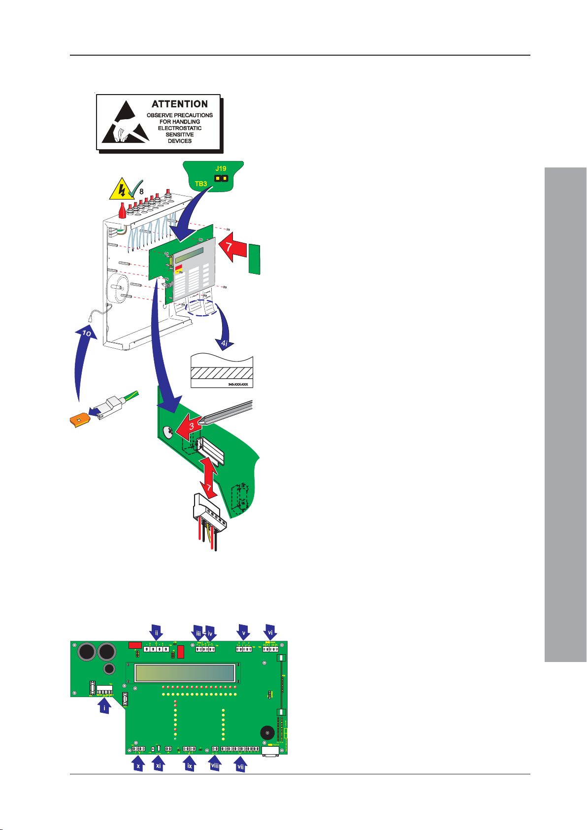
ID50 Series Panel - Installation, Commissioning & Configuration Manual
2.6 Assembling the Panel
With the back box secured to the wall and all external
cabling ready for termination, assemble the panel as
follows:
1 Ensure that all power to the panel is isolated and
observe ALL safety and anti-static precautions when
installing the PCB assembly.
2 Install all kits that require the removal of the PCB
assembly.
3 Align the PCB assembly to the supporting pillars and,
using a No. 1 Posidriv screwdriver, screw the eight
(8) M3 x 8mm SEM screws into position.
4 Fit the labels. They may require the application of a
low tack adhesive:
i Apply low tack adhesive to hatched area indicated.
ii Slide each label into position.
iii Apply slight pressure to the area along the bottom
edge of the fascia to ensure the labels are secure.
5 Apply the mains power supply and then connect the
batteries. Check the PCB assembly operates correctly
and then isolate all power to the panel.
6 At the PCB assembly:
i Noting the cable polarity, connect all cables and
secure at the correct termination blocks, see
Cables & Wiring.
ii Set all required hardware jumper configurations,
refer to the Section 4 Commissioning.
7 Fit the RS485 Interface Module PCB, if applicable,
refer to Section 2.7.1 Fitting the RS485 Interface
Module PCB.
8 Re-apply the mains power supply and then connect
the batteries.
9 Disconnect the links at the earth fault monitoring
jumper, J19, and configuration lock, J9. Then connect
the RS232 9-way ‘D’ type Data Transfer Lead
(PN 082-173) to the panel at the RS232 connector,
PL5. Using the Support Tool, transmit the latest system
configuration to the panel.
10 Remove the lead and fit the links at J9 and J19, then
fit the cover.
Installation Guide
Note: Connect the earth wire to the inner side wall of the
cover at the tag marked with the earth symbol.
Cables & Wiring
i Power Supply from transformer (TB1),
ii CFG Outputs D and C (TB3),
iii 24 V Auxiliary Power Supply (TB4),
iv Sounder Outputs B and A (TB4),
v Loop Cable Output (TB5),
vi RS485 Communications Cable (TB6),
vii FBF Communications Cable (VdS Only) (TB10),
viii FBF Power Supply (VdS Only) (TB9),
ix Digital / ÜE Cable (TB8), and
x Switchable -VE Outputs (TB2),
xi Keyswitch (PL7).
15 997-263-000-11, Issue 11
January 2010
Page 20
ID50 Series Panel - Installation, Commissioning & Configuration Manual
RS485
B A B A
RS485
B A B A
RS485
B A B A
TB6
TB6
TB6
N
L
ZONEFIRE
ZONEFAULT
DISABLE/TEST
4
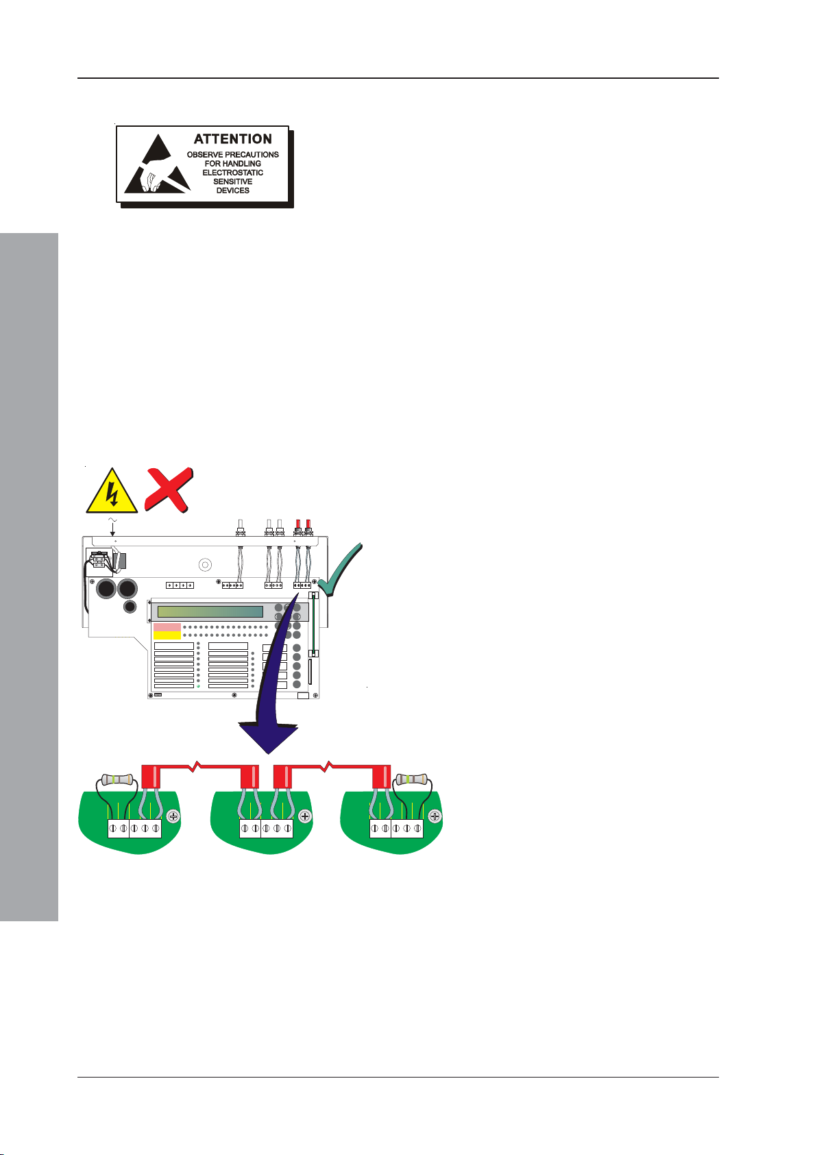
2.7 RS485 Communications Link
The panel is capable of communicating with a maximum
of sixteen (16) repeaters (active IDR-2A or passive
IDR-2P) or mimic panels (IDR-M) (for further details
concerning the repeaters refer to 997-411, IDR-2A, -2P
& -6A Repeaters User Manual or 997-412, IDR Mimic
Installation and Commissioning Manual). The panel
is connected to the repeaters in a ‘daisy-chain’
arrangement via the RS485 Communications terminal
block, TB6, on the PCB assembly. The panel must be
fitted with the RS485 Interface Module PCB at connector
PL3 on the PCB assembly (see Section 2.7.1, Fitting
the RS485 Interface Module PCB).
The two end stations require a termination resistor to be
fitted as illustrated below.
To connect a panel to an RS485 communications link:
1 Ensure the following:
i All power to the panel is isolated.
98
7
5
46
[
31
ZONEFIRE
1234567
ZONEFAULT
DISABLE/TEST
FIRE
DISABLEMENT
DELAYSACTIVE
FIREOUTPUT: FAULT/ DISABLED
FIREOUTPUT ACTIVE
PLANTALARM
POWER
TEST
8910
11 1 21314
ID50FIRE CONTROL PANEL
Complieswith EN54-2/4 1997
Periodof Manufacture 1999
FAULT
POWERSUPPLY FAULT
EARTHFAULT
SYSTEMFAULT
SOUNDER:FAULT / DISABLED
PRE-ALARM
FIRECONTROL O/P: FAULT/ DISABLED
15 16
MUTEBUZZER
EXTENDDELAY
ENDDELAY/
EVACUATE
SILENCE/
RESOUND
2
00..9
RESET
Installation Guide
TB6
TB6
ii Access to the panel electronics is possible.
ii The interlink wire is disconnected at the batteries.
2 Fit the RS485 Interface Module PCB as described in
the instructions in Section 2.7.1, Fitting the RS485
Interface Module PCB).
3 Connect the RS485 communications cable to the
RS485 Communications terminal block, TB6, refer
to Section 4.4.2, RS485 Communications Link.
Note: If connecting the panel at either end of the RS485
communications link, connect a 150R termination
resistor (supplied separately) as shown below.
4 Using the configuration procedure - refer to
Section 5.5.4.6, Number of Repeaters, configure the
panel and RS485 communications link.
If Fitted As First
Station On RS485
Comms Link
January 2010
Intermediate
Station(s)
If Fitted As Last
Station On RS485
Comms Link
16997-263-000-11, Issue 11
Page 21
ID50 Series Panel - Installation, Commissioning & Configuration Manual
A
D
E
B
F
C
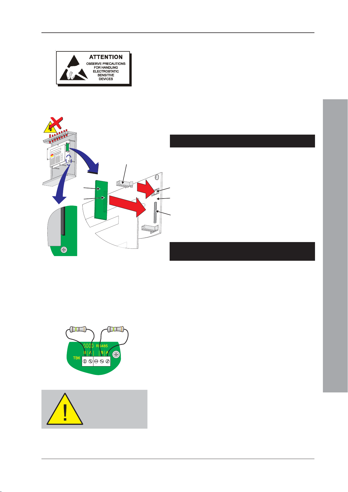
2.7.1 Fitting the RS485 Interface Module PCB
With the back box fitted to the wall, install the RS485
Interface Module PCB as described below (ensure
suitable anti-static precautions are taken):
1 Remove the cover (see Section 2.5.1) to expose the
panel electronics. Disconnect the battery interlink wire
from the batteries and isolate the mains supply.
2 Carefully fit the two plastic PCB support pillars (A) in
to the holes (B) on the right-hand side of the PCB
Assembly (C).
3 Fit the RS485 Interface Module PCB (D).
Fitting to PCB Assembly PN: 394-191-001, 002 or 003
i Make sure the RS485 Interface Module PCB
components are facing the membrane and rest the
PCB in the PCB Support pillar guides.
ii Gently ease the RS485 PCB and PCB Support
2
3
3
pillars away from the membrane and carefully slide
the RS485 PCB down the pillars until the 10-way
socket (E) aligns with the connector, PL3 (F) on
the PCB Assembly. Ensure that the components
do NOT foul on the membrane.
394-191 Issue XX
When fitted as first
station on RS485
Communications Link
Apply power BEFORE
When fitted as last
station on RS485
Communications Link
making any RS485
connections!
iii Carefully return the PCB Support pillars to their
normal position and, with a firm and constant
pushing action, connect the PCB.
Fitting to PCB Assembly PN: 394-191 Issue 4, or later,
or PCB Assembly PN: 394-390, or later.
i Make sure the RS485 Interface Module PCB
components are facing away from the membrane
and rest the PCB in the PCB Support pillars’ guides.
ii Carefully slide the PCB along the pillars until the
10-way socket (E) aligns with the connector, PL3
(F) on the PCB Assembly.
iii With a firm and constant pushing action, connect
the RS485 PCB to the PCB Assembly.
4 Connect RS485 Communications wiring at TB6 (see
left), ensuring correct polarity where applicable, and
fit the cover.
If the panel is the first or last station on the RS485
Communications Link, connect a 150R Termination
resistor to the PCB Assembly on the left-hand side
or the right-hand side terminals of TB6 respectively.
5 Apply the mains power supply and connect the battery
interlink wire. Configure the panel, refer to Section 5.
Removing the RS485 Interface Module PCB
If removing the RS485 Interface Module PCB, follow the
procedures above in reverse order.
Ensure a back-up of the current configuration has been
made and all power is isolated.
Installation Guide
17 997-263-000-11, Issue 11
January 2010
Page 22
ID50 Series Panel - Installation, Commissioning & Configuration Manual
N
L
TB3
J19
ZONEFIRE
ZONEFAULT
DISABLE/TEST
4
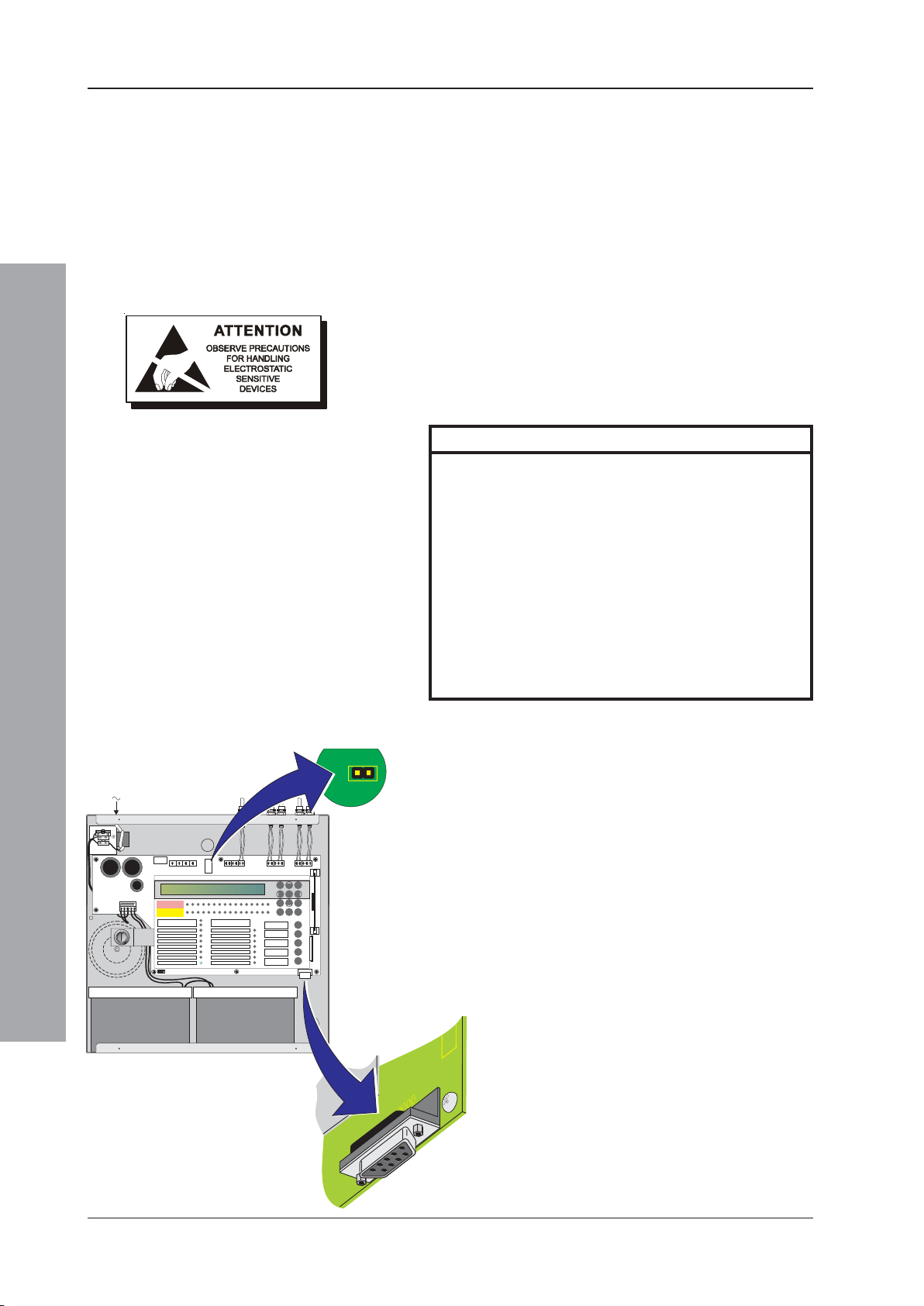
2.8 RS232 Interface Connections
The panel is fitted with a standard 9-way ‘D’-type RS232
Interface connector, located at the bottom right-hand
corner of the PCB assembly. The RS232 connector is
used for the following purposes:
a. Configuration using the PC Support Tool (refer to
997-405, ID50 Series Panel - Offline Configuration
Manual).
b. Upgrading the Panel Software (refer to 997-415, ID50
Series Panel - Upgrading Instructions).
Before starting any of the above operations ensure
suitable anti-static precautions have been taken.
The RS232 connector has the following pin out:
Pin Description
1 Data Carrier Detect (DCD)
2 Receive (RX) Data *
3 Transmit (TX) Data *
4 Data Terminal Ready (DTR)
5 GND *
6 Data Set Ready (DSR)
7 Request To Send (RTS)
8 Clear To Send (CTS)
9 Not Applicable
Installation Guide
ZONEFIRE
ZONEFAULT
DISABLE/TEST
DISABLEMENT
DELAYSACTIVE
FIREOUTPUT: FAULT/ DISABLED
FIREOUTPUT ACTIVE
PLANTALARM
1234567
FIRE
TEST
POWER
8910
ID50FIRE CONTROL PANEL
Complieswith EN54-2/4 1997
Periodof Manufacture 1999
POWERSUPPLY FAULT
EARTHFAULT
SYSTEMFAULT
SOUNDER:FAULT / DISABLED
PRE-ALARM
FIRECONTROLO/P: FAULT / DISABLED
11 121314
FAULT
15 16
MUTEBUZZER
EXTENDDELAY
ENDDELAY/
EVACUATE
SILENCE/
RESOUND
RESET
98
7
5
46
[
31
2
00..9
Note: Pin numbers marked thus ‘*’ are the only
required connections. Any others fitted will
be ignored.
A Data Transfer Lead (PN: 082-173) is required. Jumpers
must be removed as follows:
1 Remove the cover (refer to Section 2.5.1, Removing
the cover) to access the panel electronics.
2 Remove the Jumper Links J19 (earth fault monitoring)
and J9 (configuration memory lock).
Note: Refer to Section 4.3.1 Jumper Link Options/
Earth Fault Monitoring (J19) when connecting
third-party equipment to the panel.
3 Fit the Data Transfer Lead to the RS232 Interface
connector, PL5.
4 Perform required operation.
5 After satisfactory completion disconnect the lead and
then fit the jumpers.
RS232
January 2010
18997-263-000-11, Issue 11
Page 23
ID50 Series Panel - Installation, Commissioning & Configuration Manual
3 Cabling
3.1 Cabling Instructions
WARNING: Risk of electric
shock. Before working on
mains connections, ensure
mains power supply to the
panel is disconnected.
All wiring should comply with current IEE wiring
regulations (BS7671) or the applicable local wiring
regulations. Note also the requirements of EN54-14 for
cabling and interconnection of a fire detection and alarm
system.
For information on wiring inputs and outputs refer to the
appropriate module cable and wiring instructions to
identify terminals. Refer also to Commissioning,
Section 4.4 External Wiring Checks for details.
Use the following rules when installing cables:
1 Cables should be brought into the cabinet through the
20mm knockouts provided on the top face of the back
box. Ensure that all openings in the back box are
closed before connecting power to the panel. For
example, if more knockouts than required have been
removed, then block the holes with blanking glands.
This is to prevent access to hazardous voltages.
2 Tails should be of sufficient length to connect to the
appropriate termination points at the commissioning
stage.
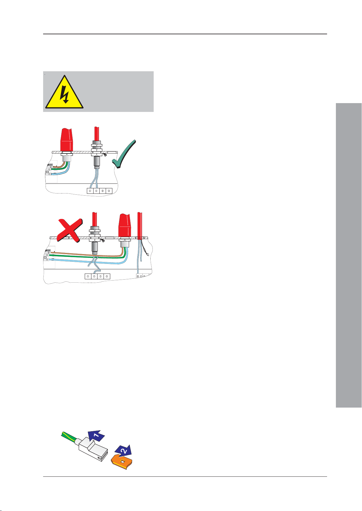
3 Cables should be screened and should be terminated
in appropriate glands to meet local wiring codes and
to preserve the integrity of the screen connection. The
cable screen is to be clamped inside the cable gland,
which must be fitted to ensure a 360o bond is formed
with the metal of the back box.
4 The supply to the panel must be provided with a
suitable and readily accessible double-pole mains
disconnect device. The mains supply must be suitably
fused and rated according to the specifications (see
Appendix 1, Specifications).
5 The knockout on the extreme left-hand side should
be used for mains cable entry. DO NOT bring mains
cables in through any other knockout holes and ensure
that the mains wiring is always separated from the
low voltage wiring. Tails of mains cables should be
provided with suitable additional sleeving before
connecting to the mains terminal block.
6 All low voltage cables should have a minimum 300Vac
rating.
General cable installation notes are given in Section 3.2,
Cable Installation Notes.
Earth Blade Connections
Note: All blade connections to earth incorporate a locking
barb. To remove this connection, pull the shroud
(1), NOT the earth wire from the earth blade
terminal (2).
Installation Guide - Cabling
19 997-263-000-11, Issue 11
January 2010
Page 24
ID50 Series Panel - Installation, Commissioning & Configuration Manual
3.1.1 Cable Terminations
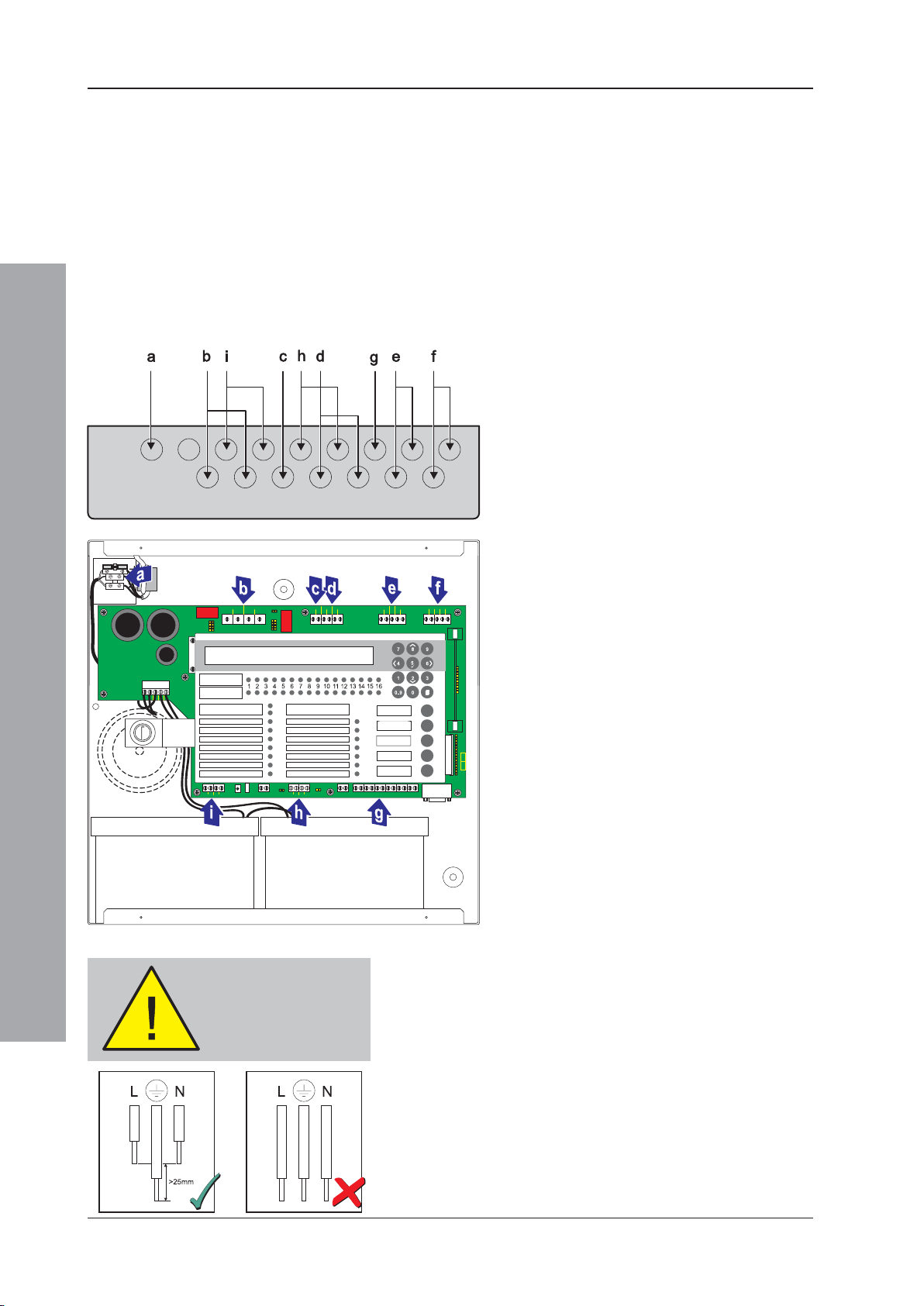
This section provides guidance on where to bring cables
into the back box for ease of termination:
a. The mains supply should be brought into the control
panel such that the cable path to the mains termination
block is kept as short as possible.
b. All loop and ancillary cable terminations should be
brought into the panel at suitable positions to ensure
tails are kept as short as possible.
The drawings below show recommended points of entry
so that cabling can meet these requirements.
Knockout/
Termination Point Cable Type
a Power supply cable
b Output D and C cables
c DC Auxiliary Supply
d Sounder Output B and A
Installation Guide - Cabling
When preparing mains
wiring for termination,
ensure the earth wire is
longer than the L(ive)
and N(eutral) wires.
Section 4.4.1, Loop Wiring,
Section 4.4.2, RS485 Communications Link,
Section 4.4.3, DC Auxiliary Output,
Section 4.4.4, Sounder Circuits Outputs A and B,
e Loop Wiring
f RS485 Communications
g FBF Connections
(Not Supported)
h Digital / ÜE
(ÜE Not Supported)
i Switched -VE Outputs
Note: The FBF Signal and Power supply
cables (g), and Digital / ÜE (h) port 2
are only valid when the panel is in VdS
mode.
For specific PCB cable termination details
see Commissioning:
January 2010
Section 4.4.5, CFG Outputs C and D,
Section 4.4.6, -VE Outputs, and
Section 4.4.7, Digital / ÜE Inputs.
20997-263-000-11, Issue 11
Page 25
ID50 Series Panel - Installation, Commissioning & Configuration Manual
3.2 Cabling Installation Notes
3.2.1 Introduction
The following notes are intended to assist installers of
analogue addressable control systems. They have been
produced from information derived from the supplier’s
technical resource and from information fed back
concerning existing systems.
3.2.2 Quality of Cable and of Cable Installation
It is vitally important that good quality cable is used, and
that correct installation techniques are followed. In general,
the following cable installation requirements must be met:
a. All cable sections must be circular to allow effective
cable clamping using the cable glands.
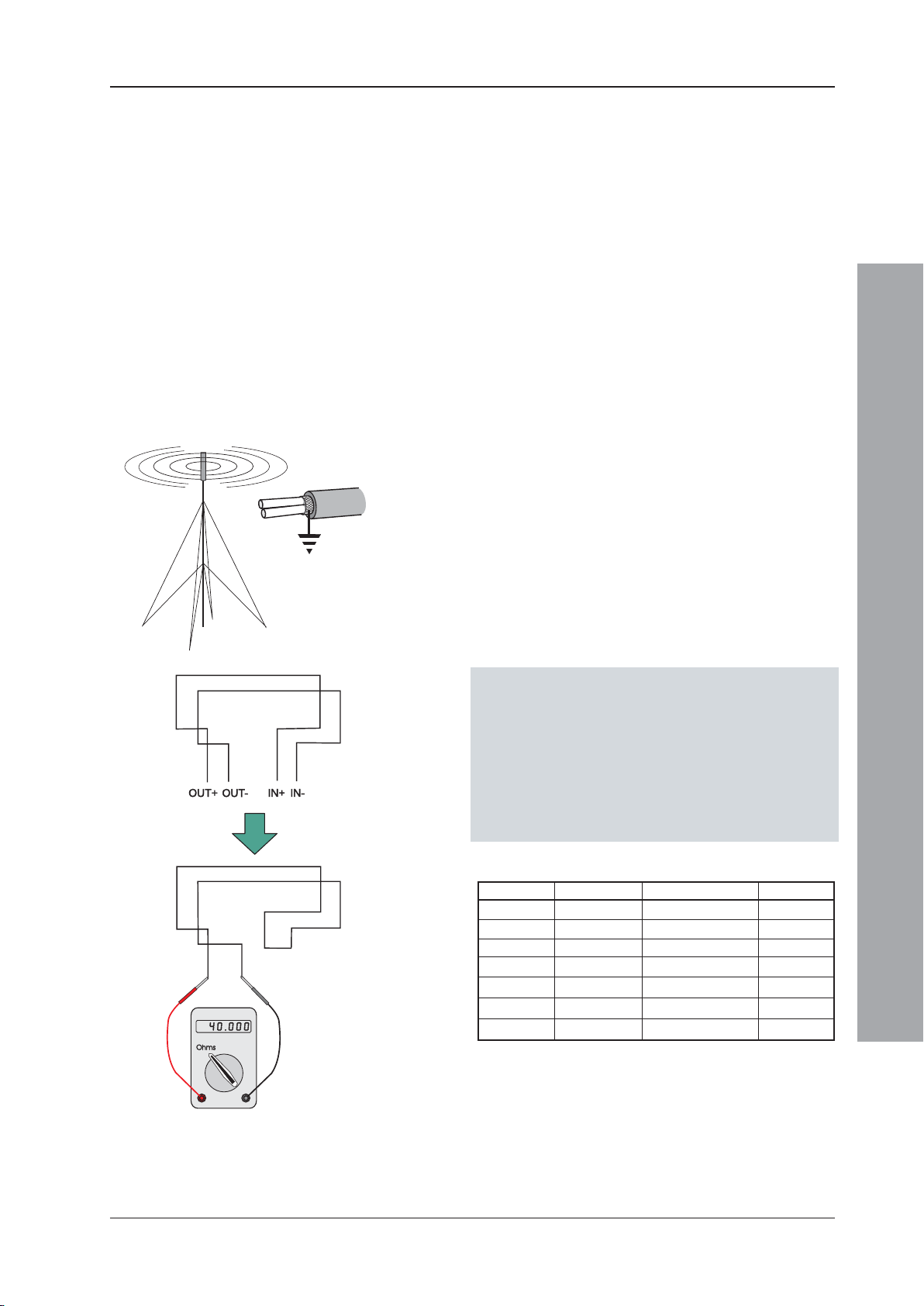
b. The cable must be screened (sheathed) to provide
protection against Radio Frequency Interference (RFI)
and the screen must be connected to earth at the
control panel.
c. Multiple earthing of the screen should be avoided.
NOTIFIER’s field products use insulated mounting
bases and back boxes to achieve this. We recommend
that this practice be continued if other connections are
made. To achieve this with MICC cable may require
the use of insulated cable glands at one end of the cable.
d. The screen must be continuous throughout the loop.
e. The maximum resistance of the loop should not
exceed 40 ohms. You may check this by joining the
return legs IN+ and IN- together and measuring across
the start legs OUT+ to OUT-. Also the cable
capacitance should be less than 0.5μF. Typically this
will allow a maximum loop length of 2000m of screened
1.5mm2 cable. Cable recommended for use is MICC
with a LSF PVC overcovering, a fire-resilient cable to
BS7629 or PVC/SWA/PVC to BS6387.
Recommended Cables:
Manufacturer Product Name Part Number Type
AEI MICC 2L1.5 Enhanced
AEI Firetech 298-052 Standard
Draka FiretufPlus FTPLUS2E1.5RD Enhanced
Draka Firetuf FTZ2E1.5 Standard
Pirelli FP Plus FP Plus 2x1.5 Red Enhanced
Pirelli FP200 Gold FP200 Gold 2x1.5 Red Standard
Arrow - 7-2-4S Not rated
1
For a definition of ‘Standard’ and ‘Enhanced’ cable requirements and their different
applications, refer to BS 5839-1 Section 26. Enhanced cable is typically required
for spur sounder outputs, while standard cables may be adequate for other firerelated I/O provided there is diverse cable routing. The multi-core cable from Arrow
is suitable for RS232 connections to a printer.
1
Installation Guide - Cabling
f. We recommend that the system should be wired in
2-core cables and each 2-core cable should be specific
to one function.
g. The RS485 communication cable used should be rated
as suitable for up to 200mA in a short circuit condition.
21 997-263-000-11, Issue 11
January 2010
Page 26
ID50 Series Panel - Installation, Commissioning & Configuration Manual
3.3 EMC Considerations
Following the above instructions and by using suitable
cables EMC problems will be avoided. In particularly
difficult EMC environments, or where non-preferred
cabling is used, it is possible to fit additional ferrite
suppressors (sleeves) to cables entering the control
panel.
3.3.1 Screen Termination
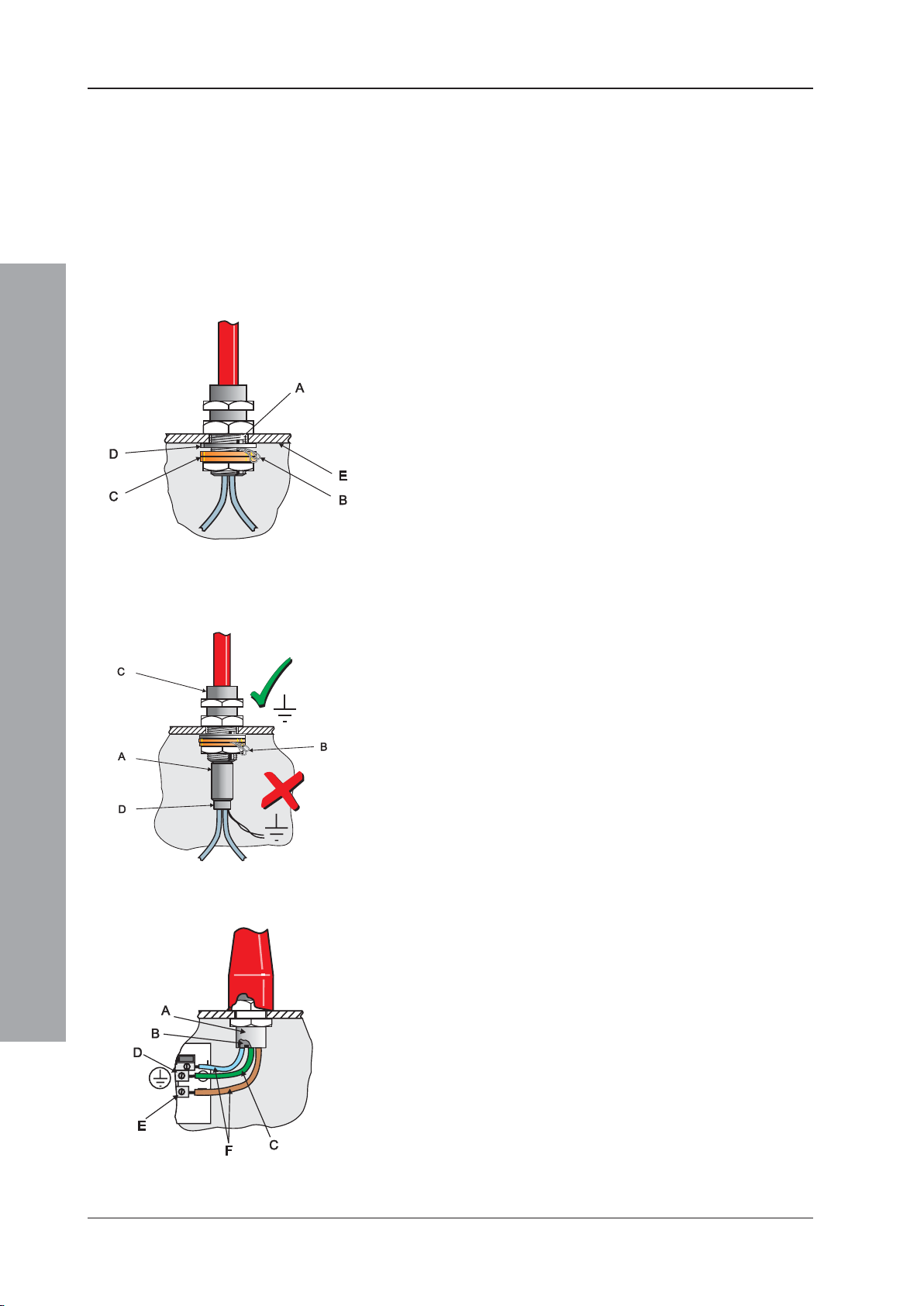
Use the following method to terminate the cable screens:
Use a metal gland with slots (A) that allow the drain
wire or screen (B) to be clamped between flat washers
(C). Use a steel locking washer (D) between the brass
washers and the internal surface of the back box (E).
This will provide the best EMC termination. Suitable
glands are the CTX range available from CMP UK
Ltd. The part chosen should fit the 20mm knockouts.
3.3.2 Ferrite Sleeves (Optional)
Ferrite sleeves are not normally required with the panel.
In difficult EMC environments, or where non-preferred
cables are used, optional ferrite sleeves should be fitted
to both the loop and sounder wiring. the ferrite sleeves
(A) are to be fitted over the conductor(s) of each cable and NOT over the screen of the cable, which should pass
outside of the sleeve. They should be fitted as close as
possible to the entry point of the cable, i.e. as near as
possible to the screen termination (B) to the metal cable
gland (C). The sleeve should be held in place using a
cable tie (D).
The ferrite sleeves are available for purchase from
NOTIFIER’s distributors (PN: 538-143).
Installation Guide - Cabling
3.4 MICC Cables
MICC cables must be fitted with metal cable glands (use
Type A2 glands) to ensure good earthing continuity and
correct termination. In particular, the mains cable requires
that the cable gland (A) is fitted with an earth tail kit (B).
The earth tail kit must be connected, using an insulated
wire (C), to the panel safety earth connection (D) at the
mains termination block (E). The bare mains wiring from
the MICC cable must be suitably-insulated (F) and
terminated in accordance with the appropriate local wiring
regulations.
January 2010
22997-263-000-11, Issue 11
Page 27

ID50 Series Panel - Installation, Commissioning & Configuration Manual
4 Commissioning
4.1 Introduction
This section describes how to bring the ID50 Series Panel
into an operational state (commissioning) ready for
configuration. To commission this series of panels follow
the steps detailed below. Information on how to configure
the panel is given in Section 5, Configuration.
1 Check that the panel is installed and assembled
correctly, refer to Section 4.2, Preliminary Checks.
2 Check internal panel configuration, Section 4.3,
Internal Checks.
3 Check and connect the external wiring, refer to
Section 4.4, External Wiring Checks.
4 Configure the panel for the particular system
requirements, refer to Section 5, Configuration.
5 Check that the system is working correctly.
4.2 Preliminary Checks
Before connecting the mains power to the panel, check
that:
a. All PCBs are correctly fitted.
b. All internal wiring is correctly connected.
c. The loop wiring and external sounder circuits have
NOT, at this stage, been connected to the PCB.
d. Check that there are no more than 10 CLIP device
addresses on a mixed-protocol loop. Be aware that
some modules, e.g. M720, M721 use more than one
loop address - the first device address taken up is
OPAL while the others are CLIP, so an M721 module
uses one OPAL and two CLIP addresses.
e. The appropriate end-of-line devices are connected to
the sounder outputs. For backwards compatibility, the
default is set for 6k8 resistor end-of-line devices.
However, an option is provided to select diode endof-line devices to meet the requirements of EN54-13,
which requires the ability to monitor for partial-open
and partial-short circuit faults. A diode is provided for
each sounder circuit should this option be selected.
Commissioning
f. The 150R termination resistors are connected to the
first and the last panels on the RS485
Communications Link.
23 997-263-000-11, Issue 11
January 2010
Page 28
ID50 Series Panel - Installation, Commissioning & Configuration Manual
4.3 Internal Checks
When all PCBs have been installed and all cabling has
been successfully checked, the following jumper links
allow the implementation of panel software or
configuration updates, as described below.
4.3.1 Jumper Link Options
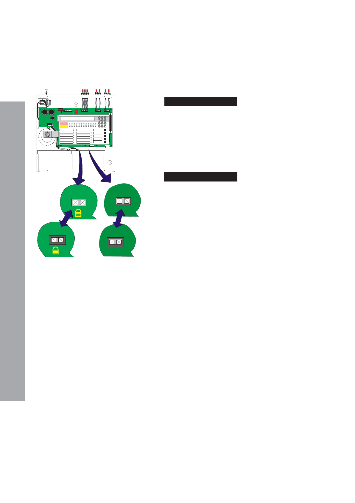
Software Upgrade (J4)
The Software Upgrade Jumper in conjunction with the
Upgrade kit is used to upgrade the panel operating
software. To enable the panel upgrade, fit a link to J4
and connect the appropriate cable. The link J4 must be
removed on completion of the upgrade (see 997-415,
ID50 Series Panel - Upgrading Instructions). This
jumper is situated to the right of the Digital/ÜE terminal
block (TB8).
DISABLEDUNLOCKED
J9
J9
LOCKED
J4
J4
ENABLED
Commissioning
Configuration Lock (J9)
The Configuration Lock Jumper is used to lock and unlock
the system configuration. If the link is fitted the system
configuration is locked and changes will NOT be allowed.
If the link is removed system configuration is possible.
The panel can only be configured with the Configuration
Lock (J9) in the unlocked position. The jumper is situated
to the left of the Digital / ÜE terminal block (TB8).
January 2010
24997-263-000-11, Issue 11
Page 29
ID50 Series Panel - Installation, Commissioning & Configuration Manual
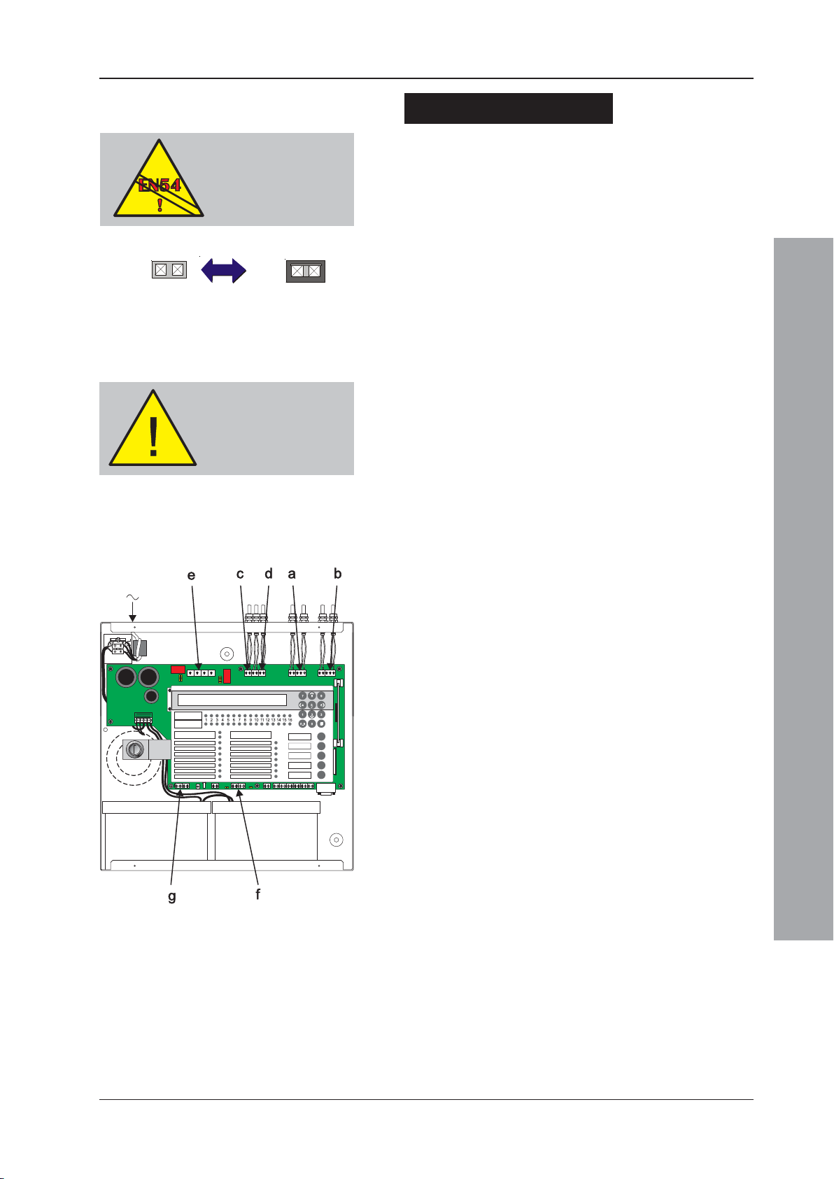
Earth Fault Monitoring (J19)
Earth fault monitoring should be enabled during normal
EN54-2 : 8.2.4c.
Earth Fault Monitoring
is required.
operation; this is the default condition and is indicated by
a fitted jumper link on J19 to the right of the CFG Outputs
C and D terminal block (TB3). To disable the earth fault
monitoring, remove the link.
J19
DO NOT remove link if
there is an existing earth
fault. If link is removed,
ensure it is fitted before
replacing front cover.
J19
ENABLEDDISABLED
The presence of an earth fault is indicated by a yellow
Earth Fault and general Fault LED.
Warning: If an earth fault already exists, DO NOT attempt
to connect additional equipment likely to cause
earth faults as damage may result, i.e. inhibiting
the monitoring will not protect the equipment.
Note: Direct connection of a VDU etc. to the RS232 serial
port D-type plug connector PL5, will result in an
earth fault and potential damage to the connecting
equipment. This fault can be removed by use of
an isolated RS232 link or by (temporarily) disabling
the earth leakage detection. Wait at least one
minute after disabling the earth fault monitoring
circuit before plugging into PL5.
4.4 External Wiring Checks
The following sections describe the procedures for
checking and connecting the external wiring:
a. See Section 4.4.1, Loop Wiring*,
b. See Section 4.4.2, RS485 Communications Link,
c. See Section 4.4.3, DC Auxiliary Output,
d. See Section 4.4.4, Sounder Circuit Outputs A and B,
e. See Section 4.4.5, CFG Outputs C and D,
f. See Section 4.4.6, -VE Outputs, and
g. See Section 4.4.7, Digital / ÜE Inputs.
* Notifier has a PC-based Loop Diagnostic Tool (LDT).
This tool is easy to use and its purpose is to reduce
the amount time spent resolving cable and wiring
termination faults. Contact Notifier Technical Support
for details.
Commissioning
25 997-263-000-11, Issue 11
January 2010
Page 30
ID50 Series Panel - Installation, Commissioning & Configuration Manual
The loop wiring MUST
be disconnected from
the panel during this
procedure
OPAL Protocol Devices
Most OPAL devices have internal isolators.
With OPAL-compatible bases the isolator is
connected across terminals +2 and +4 on
the positive loop leg. OPAL devices will
work satisfactorily on B501 bases except
the internal isolator, when fitted, cannot
be operated.
4.4.1 Loop Wiring
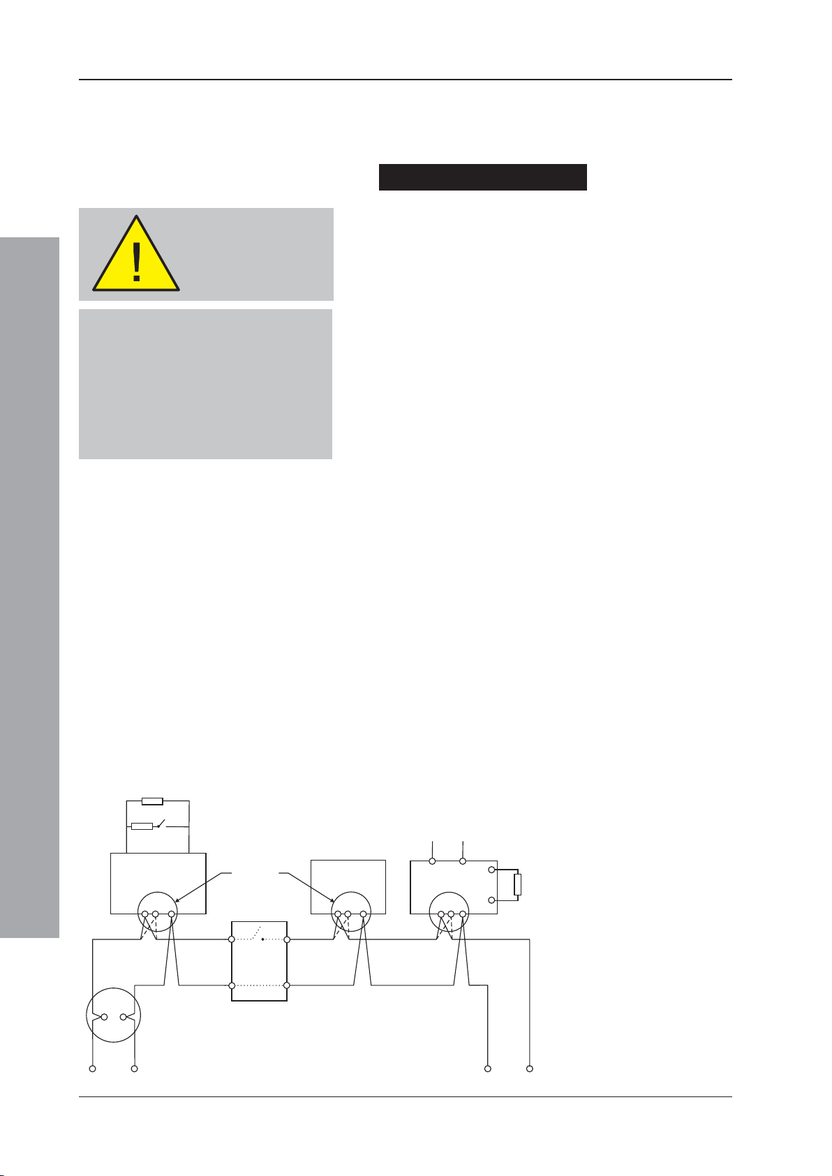
Typical connections of analogue addressable loop pair
to a loop are shown below.
Checks Before Connection
To check the Loop wiring:
1 For CLIP devices link out any isolators on the Loop
by temporarily shorting terminals 2 and 4 on each
isolator. For OPAL protocol-compatible sensor bases
(B501 AP) remove the device from the base. These
bases have +leg terminals (+2 OUT and +4 IN) that
connect automatically when the sensor is removed.
Check Appendix 1 of this manual or the LBC for OPAL
device types fitted with internal isolators.
2 These tests should then be carried out using a low-
voltage multimeter. Check the continuity of each leg
of the loop and measure the end-to-end resistance.
Verify that the total loop resistance (sum of both legs)
is less than 40 ohms. Typically, this will allow a
maximum loop length of 2,000m of screened 1.5mm
cable.
2
Commissioning
4k7
18k
Monitor used
(see Note a)
LOOP IN LOOP OUT LOOP OUT LOOP OUTLOOP IN LOOP IN
as input
A
See Note c
Isolator
(see Note b)
M500KAC/
M700KAC
Note: The cable capacitance should be less than 0.5μF.
3 Connect the meter in ‘normal’ polarity (+ve to loop +ve
and -ve to loop -ve). The meter should initially read low
resistance but this should increase as the capacitor in
each of the loop devices charges. If the meter indicates
the presence of a forward-biased diode then it is
probable that one or more of the loop devices is
connected in reversed polarity or the wiring is crossed.
4 If reversed device(s) are indicated in step 3, they may
be located by successive halving of the loop (if the
site layout makes this difficult, the affected section of
the loop can be identified from the panel fault
messages after the system has been configured and
the links in the isolators removed - CLIP devices only).
Notes:
a. A = Normally open switch
- closes under an alarm
28V Supply
Output
Module
See Note c
47k
Supervised
Load
condition.
b. To comply with the
requirements of EN54,
isolators should be fitted
between a maximum of
32 loop devices. For the
ID50 Series Panel, do not
place more than 25 loop
devices between isolators
(20 if FET isolators are
used).
See Note c
B501/B501 AP
+
Loop Start
-
January 2010
c. Refer to device
instruction sheet for
wiring terminations.
Loop Finish
+
26997-263-000-11, Issue 11
Page 31
ID50 Series Panel - Installation, Commissioning & Configuration Manual
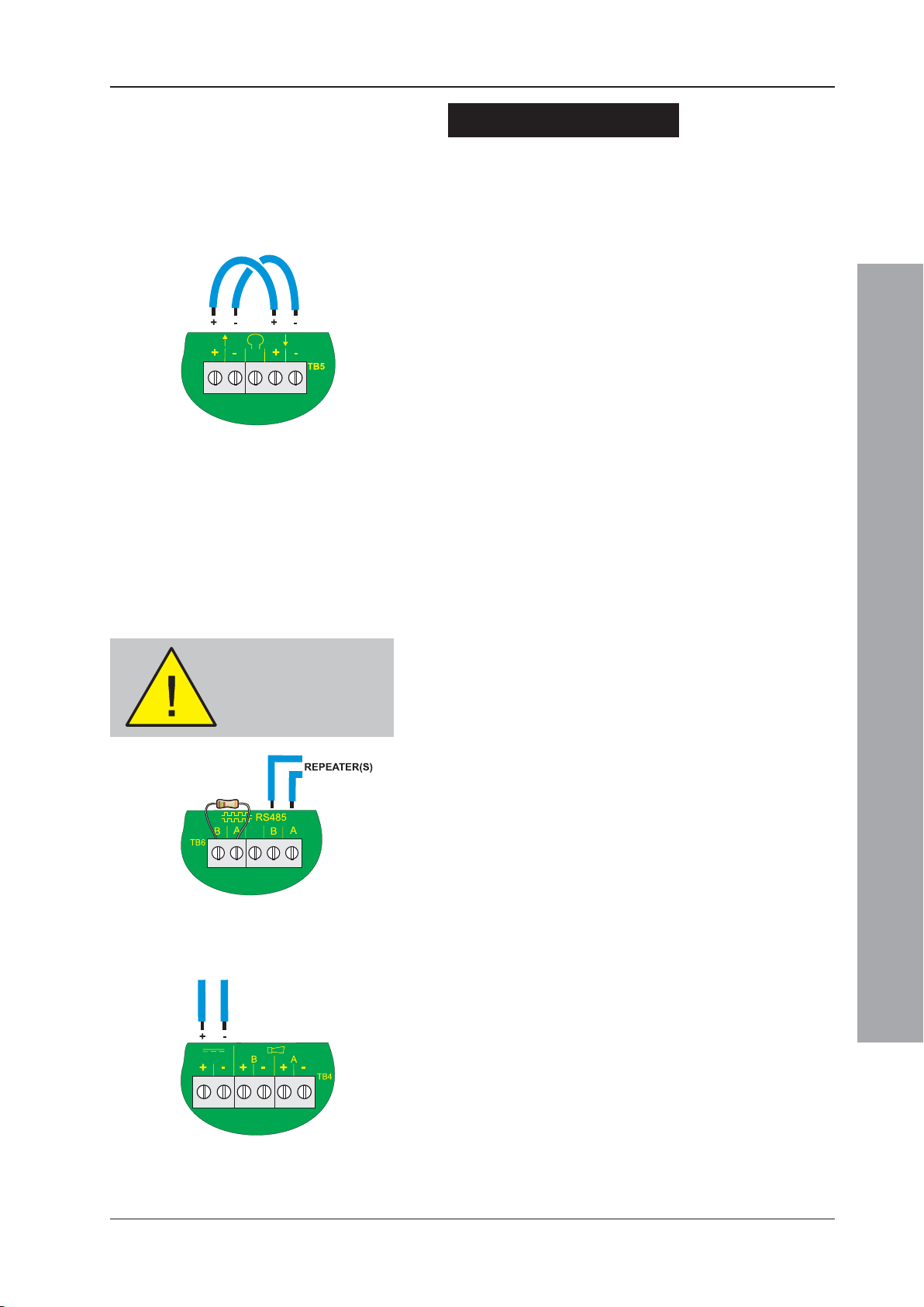
Connecting to the Panel
When the Loop wiring has been checked and found to
be satisfactory, do the following:
1 Remove the temporary links on the isolator units
(OPAL protocol-compatible sensor bases, B501 AP,
automatically link out so these can be ignored at any
addresses where devices with an internal isolator are
installed).
2 Connect the loop wiring to the panel.
When connecting, observe correct polarity! The
ends nominated as + and - must be fitted to the
correct terminals.
3 When the Loop wiring has been connected, apply the
mains supply and then fit the interlink wire to the
batteries.
4 Check the LCD and LEDs for indications of any faults.
If faults exist, correct them and reset the panel.
Apply power
BEFORE making any
RS485 connections.
5 Configure the Loop following the procedures in
Section 5.6.1, Signalling Line Circuit (SLC) Devices and/or Section 5.6.2, Signalling Line
Circuit (SLC) - Learn.
4.4.2 RS485 Communications Link
When the RS485 Communications link has been installed
in the back box, checked and found to be satisfactory:
1 Connect the RS485 Communications Link to the panel
at terminal block TB6, located on the PCB assembly,
as shown at left.
When connecting, observe correct polarity! The
ends nominated as B and A must be fitted to the
correct terminals.
2 When the RS485 Communications link has been
connected, apply the mains supply and then fit the
interlink wire to the batteries.
4.4.3 DC Auxiliary Output
BEFORE connecting any circuit to the monitored DC
Auxiliary Output, check that:
Commissioning
1 The external wiring is not short circuit.
2 There are no forward-biased diodes (as used for
example with end-of-line power monitoring relays)
connected across the external wiring.
When connecting, observe correct polarity! The
ends nominated as + and - must be fitted to the
correct terminals.
27 997-263-000-11, Issue 11
January 2010
Page 32
ID50 Series Panel - Installation, Commissioning & Configuration Manual
N
L
TB5TB4TB3
ZONEFIRE
ZONEFAULT
DISABLE/TEST
4
+
-
EOL
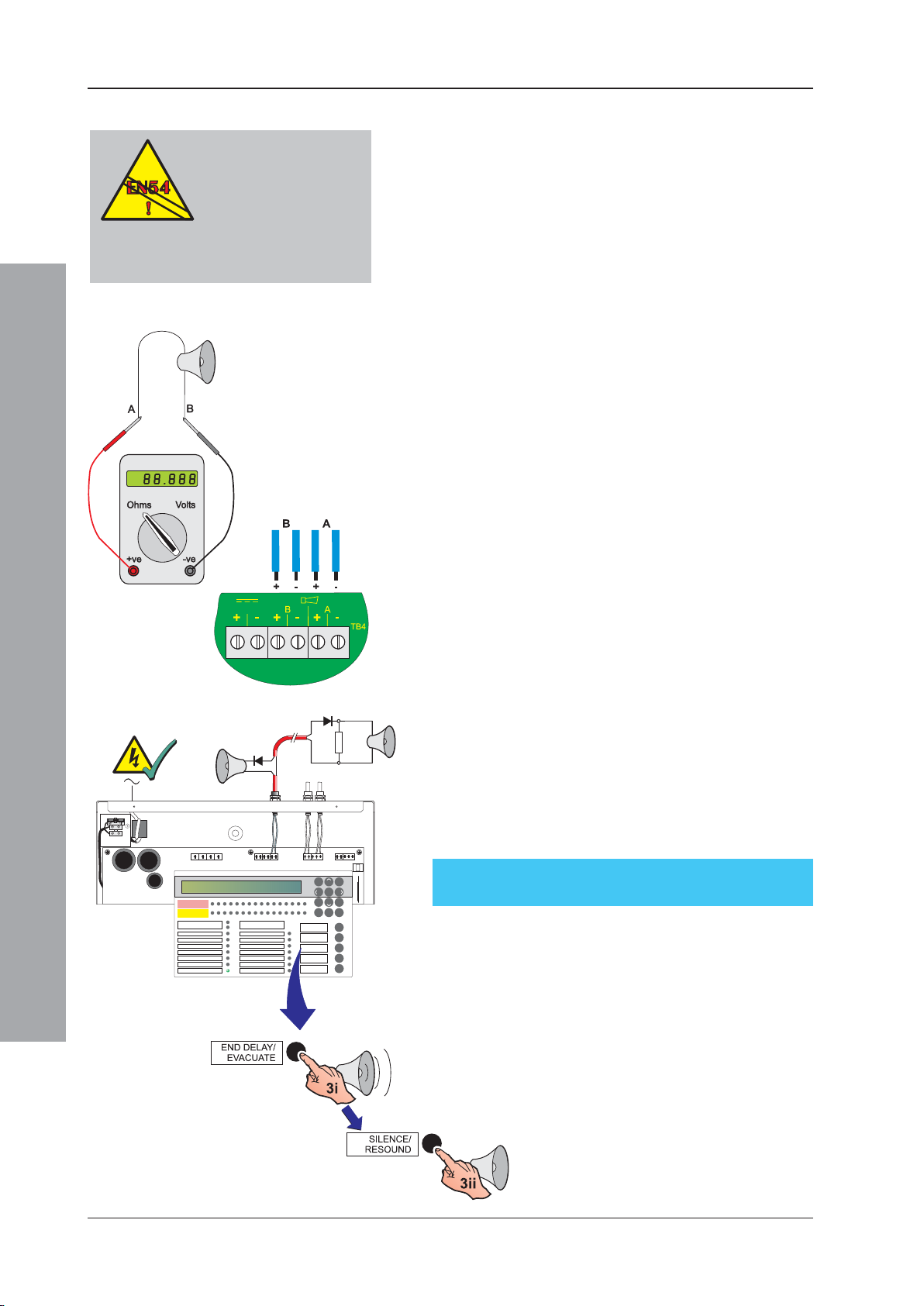
4.4.4 Sounder Circuit Outputs
EN 54-2 : 7.8
If an EN54-2 monitored
fire alarm routing
output is required an
unmonitored relay is
not suitable - use a monitored routing
output.
The sounder cicuits are designed to work either with a
resistor end-of-line (EOL) device (default) or, to comply with
the requirements for partial shorts and open monitoring
of EN54-13 (Compatibility Assessment of System
Components), where a diode EOL device is required. If
resistor EOL devices are to be used follow the first procedure
described below. If diode EOL devices are to be used refer
to the procedure described overleaf.
4.4.4.1 Using Resistor EOL Devices
Before the sounder circuits are connected it is
recommended that all detection circuits have been
checked and that there is no possibility of spurious alarm
conditions being generated. The sounders should be
polarized and suppressed using IN4002 (or similar)
diodes and the circuits should be fitted with 6k8 end-ofline resistors. Perform the following checks:
1 Use a low-voltage multimeter to check the resistance
across each of the sounder circuits:
i With the meter connected in reverse polarity (+ve
to -ve and -ve to +ve) the reading should be 6k8.
ii With the multimeter connected to the circuit in
normal polarity (+ve to +ve and -ve to -ve) the meter
may indicate a lower value. This is because of the
forward-biased diodes in series with the sounders.
Commissioning
ZONEFIRE
ZONEFAULT
DISABLE/TEST
FIRE
DISABLEMENT
DELAYSACTIVE
FIREOUTPUT: FAULT/ DISABLED
FIREOUTPUT ACTIVE
PLANTALARM
1234567
TEST
POWER
8910
ID50FIRE CONTROL PANEL
Complieswith EN54-2/4 1997
Periodof Manufacture 1999
POWERSUPPLY FAULT
EARTHFAULT
SYSTEMFAULT
SOUNDER:FAULT / DISABLED
PRE-ALARM
FIRECONTROL O/P: FAULT/ DISABLED
11 1 21314
FAULT
15 16
MUTEBUZZER
EXTENDDELAY
ENDDELAY/
EVACUATE
SILENCE/
RESOUND
RESET
98
7
5
46
[
31
2
00..9
2 If electronic sounders are used this test will not reveal
reversed devices. It is, therefore, recommended that
if the circuit resistance appears correct, the following
be done:
i Remove the 6k8 resistors from the panel outputs.
ii Connect the circuit to the panel output while
observing correct polarity.
iii If there are any reversed devices the panel will then
indicate:
‘Sounder cct. n SHORT-CCT.’.
3 When the output circuits have been connected, they
may be tested using the ‘END DELAY / EVACUATE’
pushbutton.
i Press the ‘END DELAY / EVACUATE’ pushbutton
to activate the Output circuits.
ii Press the ‘SILENCE/RESOUND’ pushbutton to
silence all activated output circuits.
iii If the outputs operated correctly press the ‘RESET’
pushbutton. If not, check all possible causes and
correct any faults that exist, then repeat Step 3.
January 2010
28997-263-000-11, Issue 11
Page 33
ID50 Series Panel - Installation, Commissioning & Configuration Manual
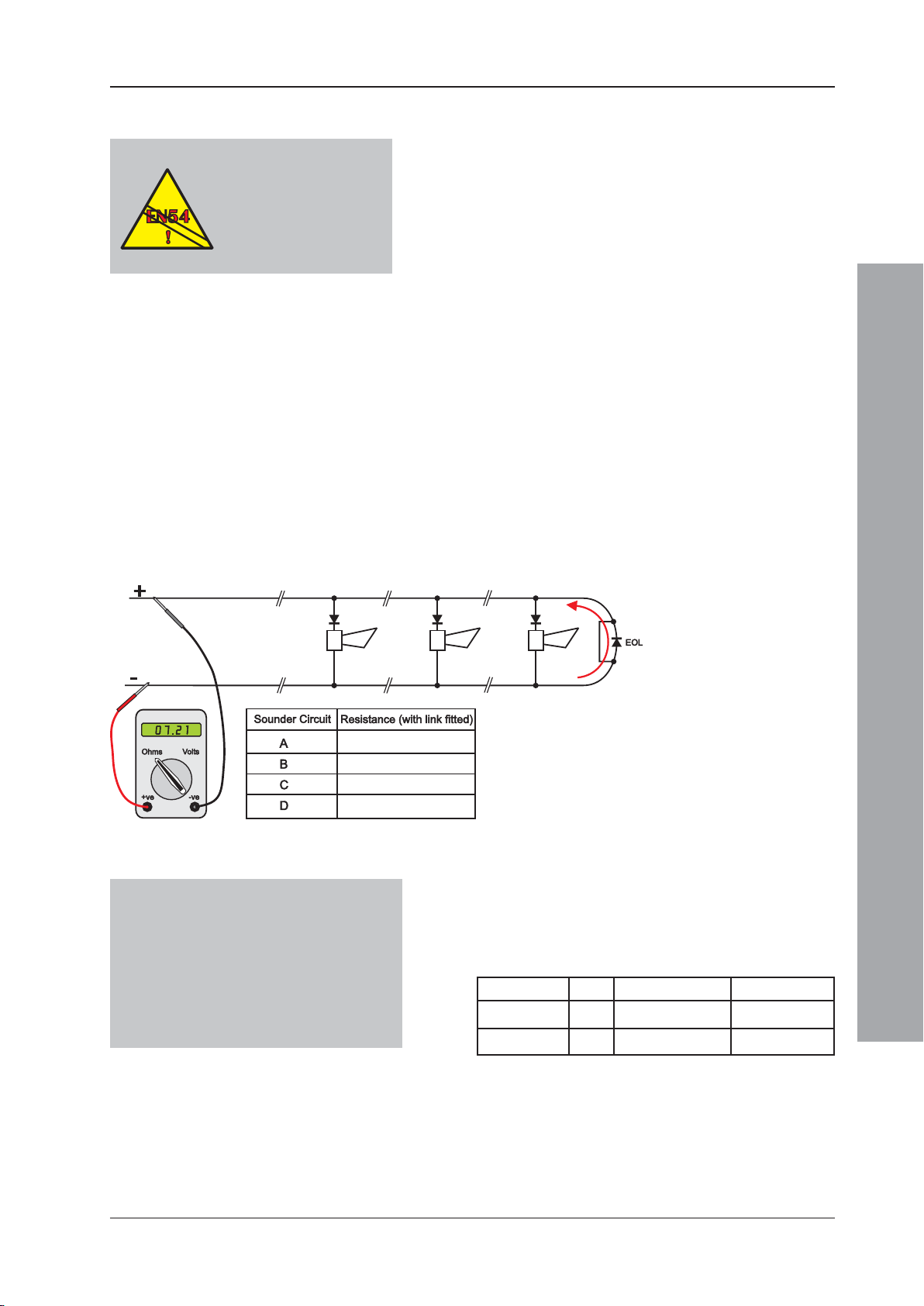
4.4.4.2 Using Diode EOL Devices
EN54-13 : 5.3.4.1,
5.3.4.2
Enablement of partial
short- and open-circuit
monitoring on sounder
outputs.
The procedure described below is based on the following
assumptions:
a. All sounder circuit cables are in situ with all sounders
connected but not yet connected to the panel.
b. The sounders are of the electronic type, polarized and
suppressed using IN4002 (or similar) diodes. For
correct operation these sounder devices require a
minimum of 15V.
c. The supplied EOL diode is fitted to each sounder
circuit - not the usual 6k8 resistor required with
previous equipment.
Note: Before the sounder circuits are connected it is
recommended that all detection circuits have been
checked and that there is no possibility of spurious
alarm conditions being generated.
Procedure:
1 Link out the end-of-line diode. Use a low-voltage
multimeter, connected in reverse polarity (+ve to -ve
and -ve to +ve), to measure the resistance of each
sounder circuit cable. Note the resistance reading in
the table provided below:
Setting sounder fault monitoring type:
• If the sounder cicuit will draw less than
350mA leave the sounder monitoring
type as ‘SDR’.
• If the sounder circuit will draw up to
700mA change the sounder monitoring
type to ‘SDH’.
Note: The cable resistance must be measured to
check that all sounders receive sufficient
voltage (15V min) for correct operation. The
cable resistance not only determines its
maximum length but also the maximum
number of sounder devices that can be
connected to ensure correct sounder operation.
2 Set the sounder type - SDR or SDH. The sounder
cannot be of type SDR if more than 350mA is being
drawn. The sounder cannot be of type SDR if the
resistance is more than 16.1Ω. If the sounder circuit
is of type SDH and the resistance is more than 8.1Ω,
a ‘OUTPUT B0 n OPEN CCT’ fault will be displayed.
Current (mA) Type Cable length (m)1 Resistance (Ω)
0-700mA SDH < 350 < 8.1
0-350mA SDR < 700 < 16.1
1
Cable lengths based on a conductor CSA of 1.5mm
Refer to Section 5.6.3.1 Output Type Setting for
details on changing the sounder type.
If the panel detects a resistance of less than 390Ω
(approx) between the sounder circuits conductors, a
partial short-circuit fault will be generated.
2
Commissioning
29 997-263-000-11, Issue 11
January 2010
Page 34
ID50 Series Panel - Installation, Commissioning & Configuration Manual
EN 54-2 : 7.7.1
One output must be
configured as a fire
output.
EN 54-2 : 7.8
If an EN54-2 monitored sounder
output is required an unmonitored
relay is not suitable. Use a
monitored sounder output.
EN 54-2 : 8.8
Either a relay1 or a
sounder output1 may be
configured as a fault
1
These outputs are not monitored and
they should not be used as a fault
routing output (EN 54-2: 8.9).
J1 & J2
1
3
5
7
2
4
6
8
output.
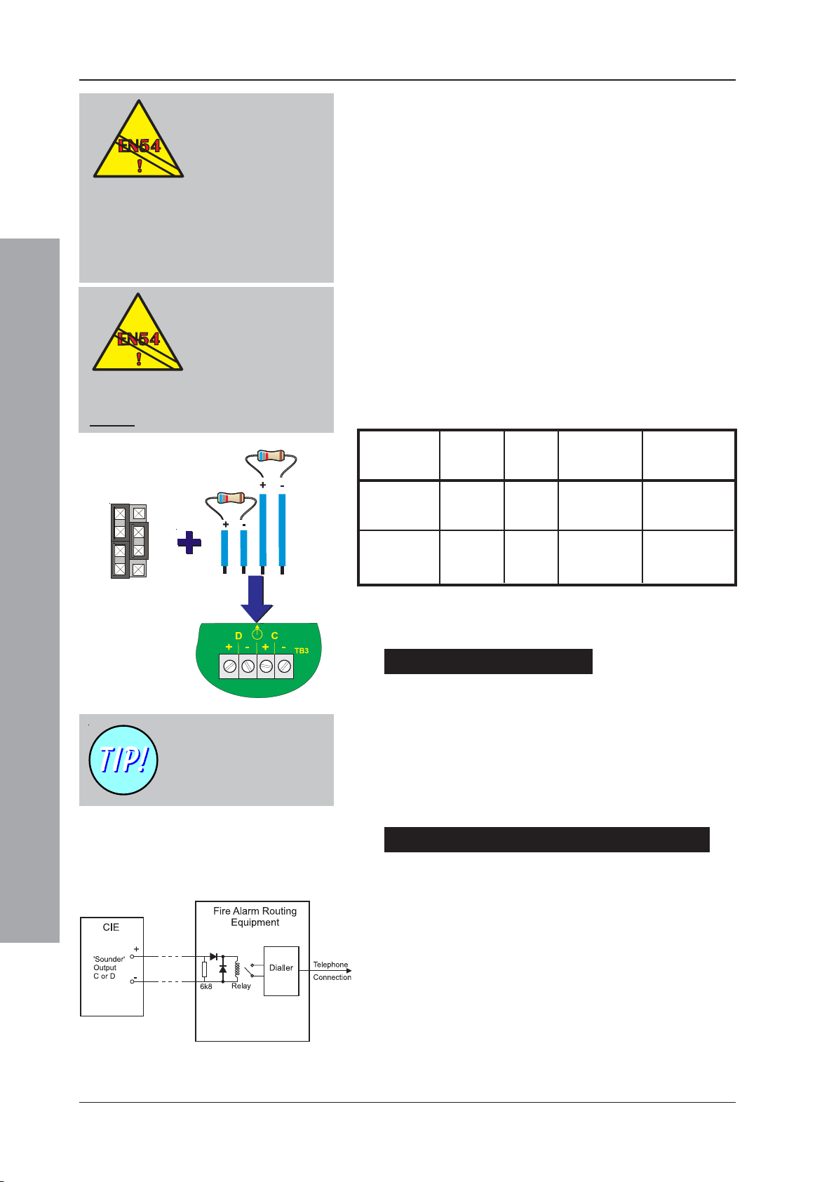
4.4.5 CFG Outputs C and D
CFG Outputs C and D can be configured as sounder or
relay output circuits using configurable jumper links.
Output C is configured using jumper link J1 and Output
D is configured using jumper link J2.
The link settings for J1 and J2 are defined in the table
below. These changes must only be made with the system
powered down and become effective automatically on
power-up.
CFG Outputs C and D can be connected as:
a. Monitored Sounder Circuits, or
b. Un-monitored Relay Outputs
Note: A sounder output can be used to drive an external
relay to provide a monitored relay output.
Before connecting CFG Outputs C and D to the PCB
assembly, the appropriate hardware links may need to
be set.
CFG Fit Jumper Sounder/ For For
OUTPUT Links Over: Remote Unmonitored Unmonitored
Relay Normally-Open Normally-Closed
Output C J1 1 & 3 1 & 2 1 & 2
(default un- 4 & 6 3 & 5 5 & 6
monitored NC) 5 & 7 7 & 8 7 & 8
Output D J2 1 & 3 1 & 2 1 & 2
(default un- 4 & 6 3 & 5 5 & 6
monitored NO) 5 & 7 7 & 8 7 & 8
Commissioning
CFG Outputs C and D have
a default configuration of
unmonitored relay outputs
(see next page).
Fault Relay - In the panel’s quiescent state a relay
configured as a fault relay is energised. Make the
appropriate ‘+’ and ‘-’ wiring connections.
Sounder Circuits
If these connections are to be configured as sounder
circuits make sure:
a. The 6k8 end-of-line resistors1 are correctly connected
to the end of the circuit, and
b. Correct polarity is used when terminating at the back
box, i.e. terminal 1 being positive and terminal 2 being
negative.
Monitored Remote Relay /Fire Routing Outputs
If these connections are to be configured to monitor for
open and short circuits make sure:
a. The 6k8 end-of-line resistors1 are connected correctly
to the end of the circuit, and
b. Correct polarity is used when terminating at the back
box, i.e. terminal 1 is positive and terminal 2 is negative.
c. A blocking diode is connected in series with the relay coil.
d. A back-emf diode should be connected across the
relay coil.
January 2010
1
Alternatively, for partial-open- and partial-short-circuit
monitoring use one of the diodes supplied with each sounder
circuit in place of the 6k8 resistor.
30997-263-000-11, Issue 11
Page 35
ID50 Series Panel - Installation, Commissioning & Configuration Manual
J2 - OUTPUT D
1
3
5
7
J1 - OUTPUT C
1
3
5
7
2
4
6
8
2
4
6
8
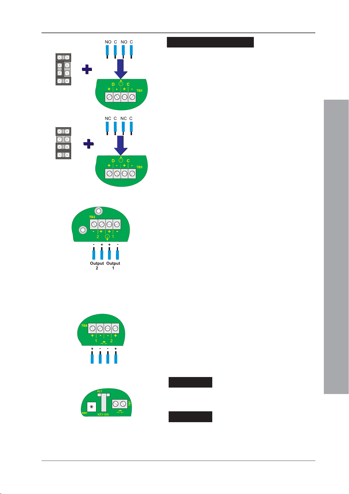
Unmonitored Relays
The unmonitored relay Output C is factory set as a fault
output, and Output D as a fire output. When configured
as volt-free relay outputs, the outputs are NOT power-
limited.
If these connections are to be configured as unmonitored
relays make sure that:
a. Jumper Links are set accordingly, refer to
Section 4.3.1, Jumper Link Options,
b. Correct polarity is used when terminating at the back
box, i.e. terminal 1 being normally-open (or normallyclosed) and terminal 2 being common contact.
Maintain adequate segregation from power-limited
wiring.
4.4.6 -VE Outputs
The two -VE Outputs, located at TB2 at the bottom left-
hand corner of the PCB assembly, are normally used to
provide a DC power supply for up to two relays located
externally to the panel.
When the -VE Outputs are initially connected, the default
software outputs are set as follows:
a. Output 1 - Pre-Alarm and
b. Output 2 - Plant Warning.
During commissioning these outputs can be individually
configured to become active if any fire alarm, pre-alarm,
fault or plant warning conditions occur (see Section 5,
Configuration).
4.4.7 Digital / ÜE Inputs (TB8)
These inputs are located at the bottom centre of the PCB
assembly. Digital Input 1 can be configured for use as
either a Day Mode or Class Change function. To select
the required function use the ‘Digital Input 1’ menu, see
Section 5.5.3.8 Digital Input 1.
Digital Input 2 is currently not supported.
4.4.8 Switch Connections
KEY-SW
The Key Switch connector is a digital input on the PCB.
Operation of the key switch permits access at level 2.
Commissioning
Cover Switch
This connector is not used.
31 997-263-000-11, Issue 11
January 2010
Page 36
ID50 Series Panel - Installation, Commissioning & Configuration Manual
4
N
L
2
2
ZONEFIRE
ZONEFAULT
DISABLE/TEST
4
4.5 Powering the Panel
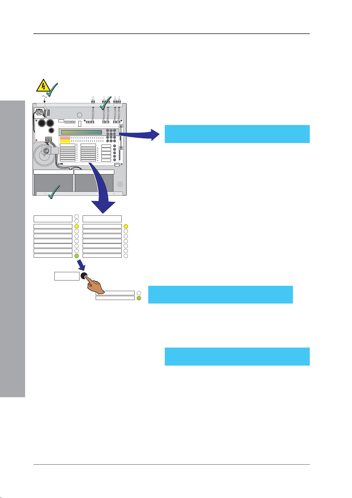
To power up an ID50 Series panel:
1 Ensure all wiring is terminated correctly and all PCBs
are fitted correctly.
2
1
7
98
5
46
[
31
ZONEFIRE
1234567
ZONEFAULT
DISABLE/TEST
FIRE
DISABLEMENT
DELAYSACTIVE
FIREOUTPUT: FAULT/ DISABLED
FIREOUTPUT ACTIVE
PLANTALARM
POWER
TEST
8910
ID50FIRE CONTROL PANEL
Complieswith EN54-2/4 1997
Periodof Manufacture 1999
POWERSUPPLY FAULT
EARTHFAULT
SYSTEMFAULT
SOUNDER:FAULT / DISABLED
PRE-ALARM
FIRECONTROL O/P: FAULT/ DISABLED
11 121314
FAULT
15 16
MUTEBUZZER
EXTENDDELAY
ENDDELAY/
EVACUATE
SILENCE/
RESOUND
2
00..9
RESET
2 With the batteries in the back box, connect the mains/
battery supply wiring plug to the power socket, between
the transformer secondary fuse (FT1) and the battery fuse
(FC1). Turn on the mains supply. The panel will display
CPU RESTART with the buzzer sounding, and the FAULT,
SYSTEM FAULT and ‘POWER’ LEDs will illuminate.
FAULT 01/01 00:00
CPU RESTART
3 Connect the battery power supply (refer to
Section 4.5.2 Batteries).
4 When powered up, press the RESET button (then enter
an appropriate access code if required). The panel should
settle to a quiescent state. The LCD should display the
‘Status: NORMAL’ message unless fault(s) are present
on the system. The internal buzzer will sound intermittently.
3
FIRE
DISABLEMENT
TEST
DELAYS ACTIVE
FIRE OUTPUT: FAULT / DISABLED
FIRE OUTPUT ACTIVE
PLANT ALARM
POWER
RESET
POWER SUPPLY FAULT
EARTH FAULT
SYSTEM FAULT
SOUNDER: FAULT/ DISABLED
PRE- ALARM
FIRE CONTROL O/P: FAULT/ DISABLED
Commissioning
January 2010
FAULT
PLANT ALARM
POWER
Note: If the panel indicates fault(s) are present, clear
them before you proceed further with the
commissioning procedure.
5 When all fault LEDs have been extinguished, the
system is ready for testing, see Section 4.7,
Commissioning Tests.
Note: The panel may be powered up satisfactorily from
batteries alone. However, first ensure the batteries are
fully charged to avoid the risk of the panel powering
down due to insufficient voltage being available.
Status: NORMAL
Sat 05/01/2002 00:00:00
4.5.1Start-up Language Selection
At panel start-up, and with a non-configured memory, you
will be prompted to select the appropriate panel language
from a displayed screen similar to the one below:
1: English 2: España 3: Portugues
4: Islanska 5: Italiano
Press the appropriate numeric pushbutton to select the
desired language. If a selection is not made within 30 secs
the panel will use the first language listed. The list of
languages may vary from those listed above.
Note: If the memory is unlocked (refer to Section 4.3.1 Jumper
Link Options) selection of the desired language will be
stored and this language will be used the next time the
panel is re-started. If the memory is locked when a
language selection is made, the panel will not store this
change and the Startup Language screen will be
displayed again at the next panel startup. However, the
language can be changed at any other time using
the ‘Language’ setup menu (refer to Section 5.5.1).
32997-263-000-11, Issue 11
Page 37
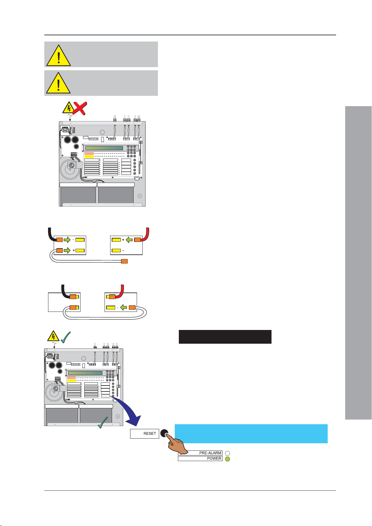
ID50 Series Panel - Installation, Commissioning & Configuration Manual
N
L
ZONEFIRE
ZONEFAULT
DISABLE/TEST
4
N
L
ZONEFIRE
ZONEFAULT
DISABLE/TEST
4
2
CAUTION- ENERGY HAZARD!
NEVER short the battery
terminals.
CAUTION- RISK OF EXPLOSION!
If battery is replaced with an
incorrect type.
98
7
5
46
[
31
2
15 16
11 121314
00..9
MUTEBUZZER
FAULT
EXTEND
DELAY
ENDDELAY/
EVACUATE
SILENCE/
RESOUND
RESET
Battery 2
TB2 (0 V)
Battery 1
ZONEFIRE
1234567
ZONEFAULT
DISABLE/TEST
FIRE
DISABLEMENT
DELAYSACTIVE
FIREOUTPUT: FAULT/ DISABLED
FIREOUTPUT ACTIVE
PLANTALARM
POWER
8910
TEST
POWERSUPPLY FAULT
EARTHFAULT
SYSTEMFAULT
SOUNDER:FAULT/ DISABLED
FIRECONTROLO/P: FAULT / DISABLED
TB2 (BAT +)
PRE-ALARM
4.5.2 Batteries
The ID50 Series Panel back box holds up to two 12V,
12Ah batteries. The batteries are not supplied with the
panel. A valve-regulated, lead-acid type MUST be used.
To avoid contact damage resulting from repeated
connection point arcing, it is recommended that the mains
is connected before the batteries.
To connect the batteries:
1 Externally isolate the mains supply at the third-party-
supplied isolation unit, remove the cover and fit the
batteries in the back box. If not done already, connect
the mains/battery/ supply wiring plug to the power
socket, between the transformer secondary fuse (FT1)
and the battery fuse (FC1).
2 Connect the red wire from the terminal block, TB2
(BAT+) to the positive terminal of battery 2 and the
black wire from the terminal block, TB2 (0V) to the
negative terminal on battery 1.
Connect one end of the interlink cable to battery 1
positive terminal only. DO NOT connect both ends of
the interlink cable at this stage.
3 Turn on the AC mains supply and verify that after
power-up:
i The panel indicates ‘CPU RESTART’.
ii The buzzer sounds.
4
Battery
1
Battery
2
iii The FAULT and SYSTEM FAULT LEDs illuminate.
4 Connect the interlink cable to the negative terminal
on battery 2.
5 Reset the panel and check that the LCD displays the
‘Status: NORMAL’ message and that the FAULT and
SYSTEM FAULT LEDs extinguish.
Commissioning
5
Battery Disposal
As a minimum, replace the batteries every four years.
Always dispose of the batteries in accordance with the
ZONEFIRE
ZONEFAULT
DISABLE/TEST
FIRE
DISABLEMENT
DELAYSACTIVE
FIREOUTPUT:FAULT / DISABLED
FIREOUTPUT ACTIVE
PLANTALARM
1234567
TEST
POWER
8910
POWERSUPPLY FAULT
EARTHFAULT
SYSTEMFAULT
SOUNDER:FAULT/ DISABLED
PRE-ALARM
FIRECONTROLO/P: FAULT / DISABLED
11 121314
FAULT
1516
MUTEBUZZER
EXTENDDELAY
ENDDELAY/
EVACUATE
RESOUND
7
46
SILENCE/
RESET
5
[
31
2
00..9
battery manufacturer’s recommendations and local
regulations.
98
Status: NORMAL
Sat 05/01/2002 00:00:00
33 997-263-000-11, Issue 11
January 2010
Page 38
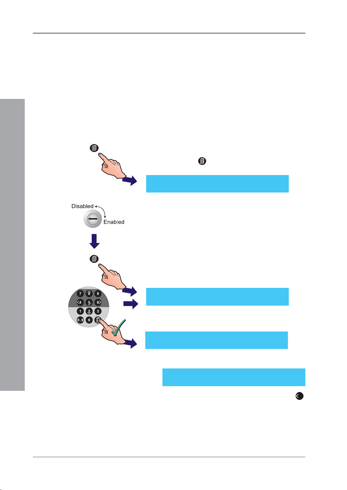
ID50 Series Panel - Installation, Commissioning & Configuration Manual
4.6 Configuration and Handover
After all external wiring has been connected to the panel
and with the LCD displaying the ‘Status: NORMAL’
message, the panel can be configured for the particular
system requirements. Refer to Section 5, Configuration.
After configuration has been completed and any faults
revealed have been rectified, the system will be ready
for commissioning tests (see Section 4.7,
Commissioning Tests), as required by the appropriate
standards, prior to handover to the user.
Panel configuration is performed via the ‘Commission’
menu:
1
2
Commissioning
1 When the ‘Status: NORMAL’ message is displayed,
press the ‘ ’ button. The LCD prompts for entry of
an access code as displayed below:
ACCESS TO MENUS RESTRICTED
Enter Level 2/3 Passcode: . . . . < : BackSp
2 Either turn the keyswitch or, using the numeric keypad
(see 997-264-000-X, ID50 Series Panel - Operating
Manual, Section 4.6, Numeric Keys), enter either the:
a. Level 2 access code, or
b. Level 3 access code.
Refer to Appendix 1 - Specifications for the default
passcodes.
If the correct Level 2 access code (User) is entered,
the Access Level 2 Menu and a user number (U0 - U9)
is displayed in the top left-hand corner of the LCD
(this is always U9 if the keyswitch is used):
[U0] 1:Test 2:Disable/Enable 3:Clock
4:View Mode 5:Commission
or if the Level 3 access code (Service) is correctly
entered, the LCD displays [S1] in the top left-hand
corner:
[S1] 1:Test 2:Disable/Enable 3:Clock
4:View Mode 5:Commission
January 2010
If an incorrect access code is entered, the LCD displays
a message:
ERROR - INCORRECT PASSCODE ! ! !
To return to the normal quiescent state, press the ‘4’
button.
34997-263-000-11, Issue 11
Page 39
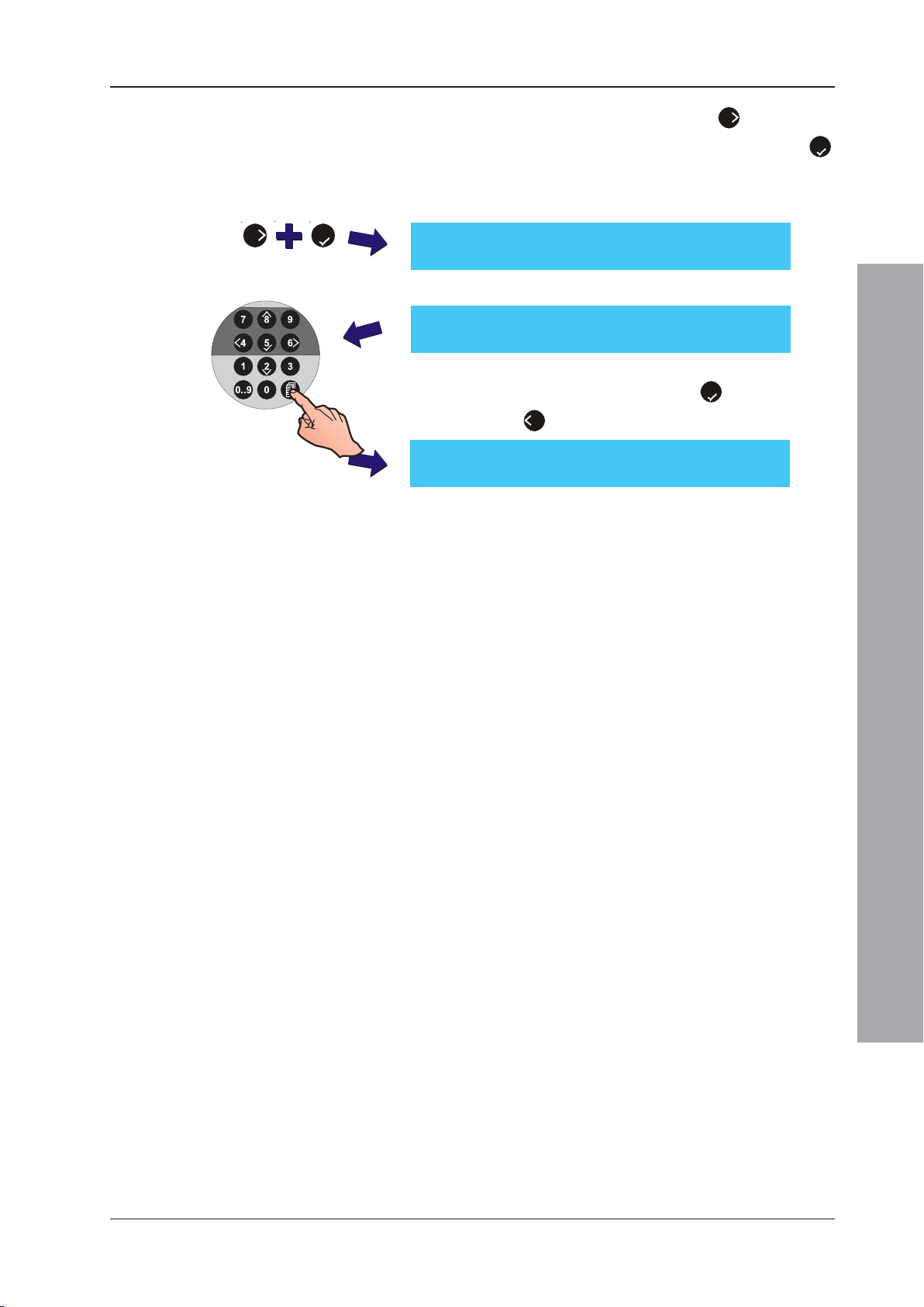
ID50 Series Panel - Installation, Commissioning & Configuration Manual
3 Using the numeric keypad, press ‘
6
’ to select the
6 5
Commissioning option and confirm using the ‘
pushbutton. The Commissioning option is
automatically displayed if a Level 3 passcode was
previously entered.
[S1 COMM] 1:Setup 2:Circuit
3:CBE Rules 4:Zones 5:Access ¦ : More
If a Level 2 passcode was entered the LCD prompts:
COMMISSION MODE ACCESS
Enter Level 3 Passcode: . . . . < : BackSp
4 Enter the correct Level 3 passcode using the numeric
keypad and confirm using the ‘5’ pushbutton (or
press ‘4’ to cancel the last operation).
[S1 COMM] 1:Setup 2:Circuit
3:CBE Rules 4:Zones 5:Access ¦ : More
4.7 Commissioning Tests
The following paragraphs list tests that should be performed
after configuration has been completed. A successful result
from these tests indicates that the panel is working properly.
5
’
4.7.1 Test LEDs
This procedure is described in the ID50 Series Panel -
Operating Manual, 997-264-000-X, Section 4.8.1.
4.7.2 Test LCD
This procedure is described in the ID50 Series Panel -
Operating Manual, 997-264-000-X, Section 4.8.2.
4.7.3 Test Zones
This procedure is described in the ID50 Series Panel -
Operating Manual, 997-264-000-X, Section 4.8.3.
4.7.4 Test Auto High Test
This procedure is described in the ID50 Series Panel -
Operating Manual, 997-264-000-X, Section 4.8.4.
4.7.5 Test Outputs
This procedure is described in the ID50 Series Panel -
Operating Manual, 997-264-000-X, Section 4.8.5.
4.7.6 Test Buzzer
Commissioning
This procedure is described in the ID50 Series Panel -
Operating Manual, 997-264-000-X, Section 4.8.6.
4.7.7 Test Keyboard
This procedure is described in the ID50 Series Panel -
Operating Manual, 997-264-000-X, Section 4.8.7.
35 997-263-000-11, Issue 11
January 2010
Page 40
ID50 Series Panel - Installation, Commissioning & Configuration Manual
4.8 Sensors and Modules
Each of these devices is packaged with an instruction
leaflet showing the correct interconnections for various
applications. OPAL Protocol devices are now supported.
To include the internal isolator (not all OPAL devices
incorporate these) use the B501 AP sensor base which
has an additional positive leg loop wiring connector for
the device’s internal isolator.
4.8.1 EN54 Requirements
EN54-2 : 12.5.2
Maximum of 32
Sensors and/or MCPs
between isolators.
BS5839 Part 1
Use OPAL-protocol
compatible MCPs on
OPAL or mixed protocol
loops to meet the 3 second
Commissioning
response time.
Isolators
Isolators must be used on the analogue loop to separate
sensors and/or MCPs, including any conventional zone
detectors and/or MCPs connected.
- CLIP devices or OPAL devices without internal
isolators: To comply with the requirements of EN54-
2, isolators should be fitted between a maximum of
32 loop devices. For the ID50 Series, do not place
more than 25 CLIP loop devices between isolators
(20 if FET isolators are used).
- OPAL devices with internal isolator fitted when used
with the B501 AP sensor base: Ensure loop the
complies with the requirements of EN54-2.
Failure to comply contravenes the requirements of
EN54-2 in the event of a transmission path fault.
4.8.2 BS5839 Part 1 Requirements
All MCPs should be OPAL protocol compatible on OPAL
or mixed OPAL and CLIP protocol loops
Note: CLIP MCPs may be installed but the panel may
not to meet the 3 second response time required
by BS5839 Part 1. If CLIP MCPs are used the
maximum number of CLIP devices MUST be 6 to
allow all CLIP devices to have been polled in 3
seconds.
January 2010
NEVER use a high
voltage tester on
the loop.
4.8.3 Loop Wiring Testing
Before connecting the panel or devices, the wiring of the
loop may be tested for continuity and insulation. Once
any components are connected, including isolators or
devices with internal isolators, no high-voltage testers
such as Meggers may be used on the loop; low-voltage
testers such as multimeters may be used.
Note: If isolators or devices with an internal isolator are
fitted (without power on the loop), the +ve
conductor of the loop will be open circuit.
36997-263-000-11, Issue 11
Page 41
ID50 Series Panel - Installation, Commissioning & Configuration Manual
5 Configuration
5.1 Introduction
The following sections contain instructions to configure
a panel.
For each configuration option, a brief description of its
purpose is given, followed by the configuration procedure
accompanied by illustrations of appropriate LCD displays.
The panels use menu-driven software which is divided
into Level 2 Configuration Options (see Section 5.3) and
Level 3 Configuration Options (see Sections 5.4 - 5.11).
5.2 Navigation and Number Entry
To navigate around the menus and enter numeric values,
refer to the ID50 Series Operating Manual 997-264-000-X,
Section 4.6.
5.3 Level 2 Configuration Options
The Level 2 Configuration Options are described in the
ID50 Series Panel Operating Manual 997-264-000-X.
The applicable sections are listed below:
a. Test - Section 4.9
b. Disable/Enable - Section 4.10
c. Clock - Section 4.11
d. View Mode
e. Commissioning - Section 4.13
f. Print - Section 4.14
1
With ID60 panels there is a View Mode menu option
for displaying VIEW, Optiplex and SMART 4 sensor
maintenance log data (Access Level 3 required).
The Operating Manual also includes a Level 2 menu
map.
For the default Level 2 passcode refer to Appendix 1 -
Specifications.
1
- Section 4.12
Configuration Mode
37
997-263-000-11, Issue 11
January 2010
Page 42
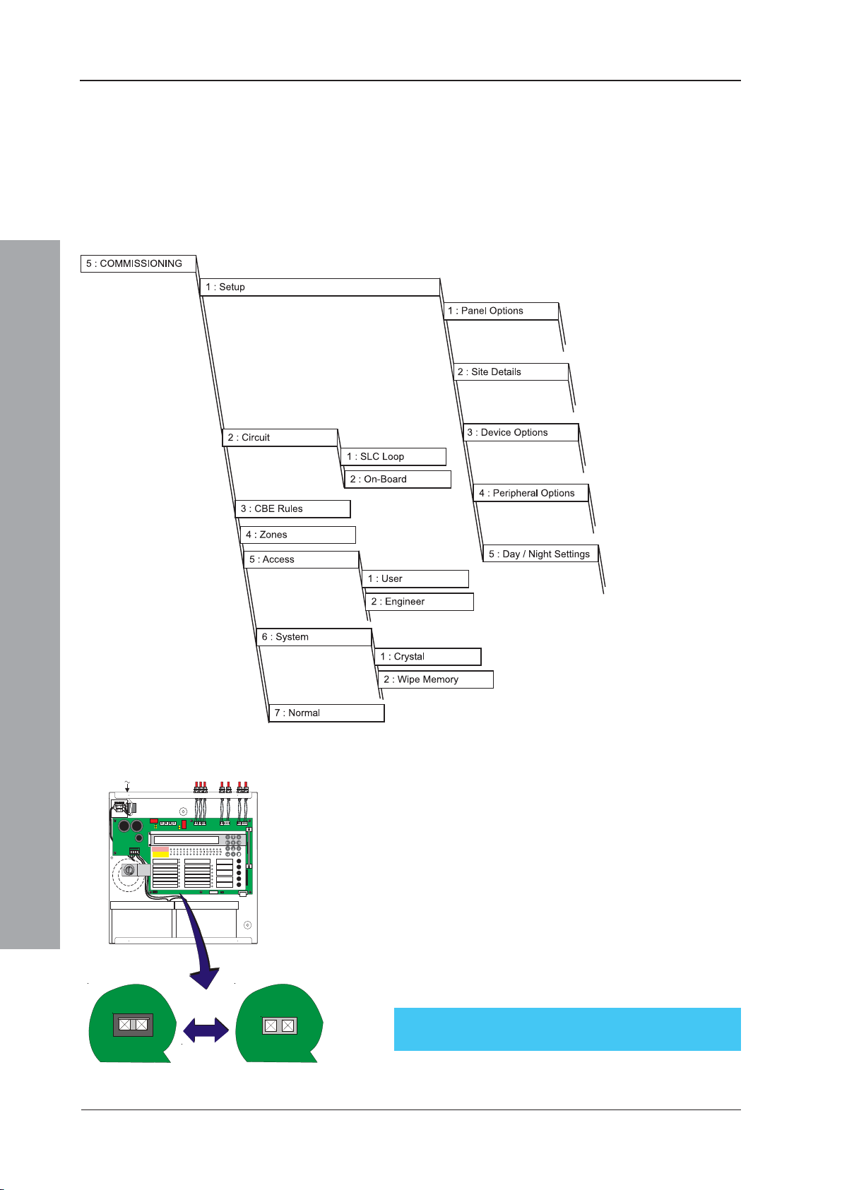
ID50 Series Panel - Installation, Commissioning & Configuration Manual
5.4 Level 3 Configuration Options
The Level 3 Configuration Options allow you to configure
the panel. These Options are listed in the menu map at
left. The default Level 3 passcode is given in
Appendix 1 - Specifications.
Before any configuration changes can be made, the memory
lock must be set to the unlocked position (see below).
Configuration Mode
J9J9
MEMMEM
LOCKED
997-263-000-11, Issue 11
January 2010
UNLOCKED
Memory Lock Jumper Link
Jumper link J9 locks/unlocks the system configuration.
J9 is located to the left of terminal block TB8 (Digital / ÜE).
To configure the panel, J9 must be in the ‘unlocked’
position (link NOT fitted).
Fit the link to the jumper (J9) before returning to
normal operation.
Any attempt to access a configuration menu option while
the link is fitted will cause the following message to be
briefly displayed:
Memory is Locked!
38
Page 43
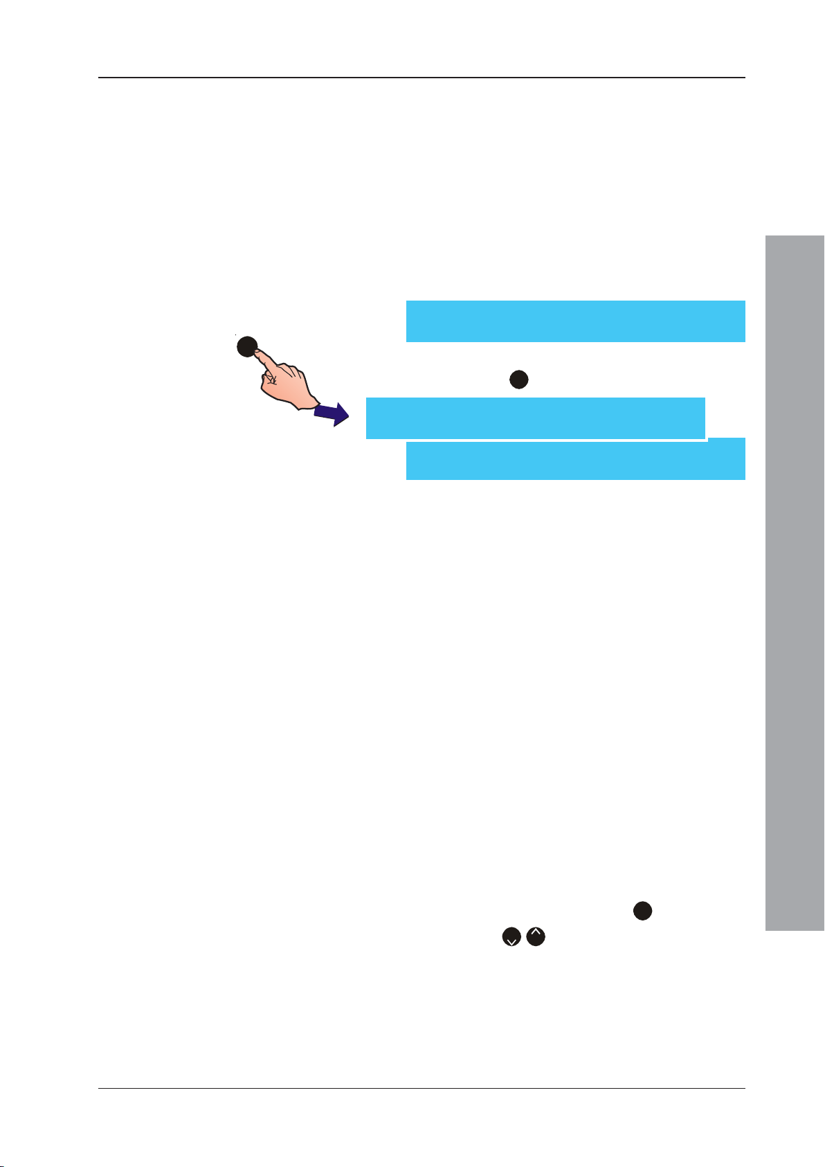
ID50 Series Panel - Installation, Commissioning & Configuration Manual
5.5 Setup Options
The Setup options menu allows the configuration of all
site-specific panel settings. These configurable settings
are sub-divided into the following categories:
a. Panel Options
b. Site Details
c. Device Options
d. Peripheral Options
e. Day/Night Settings
[S1 COMM] 1 : Setup 2 : Circuit
3 : CBE Rules 4 : Zones 5 : Access ¦ : More
1
With the Commissioning menu displayed and using the numeric
keypad, press the ‘1’ button to display the Setup menu:
[S1 Setup] 1: Panel Options
2: Site Details 3: Device Options ¦ : More
[S1 Setup] 4: Peripheral Options
5: Day / Night Settings ¦ : More
Use the numeric keypad to select the appropriate option
from the Setup menu as described below.
5.5.1 Panel Options
This allows you to set or change the basic panel
configuration settings such as the user interface options
and operator access settings. The Panel Options menu
comprises the following configurable options:
a. Language (See Note 1)
b. Date Format
c. Control Keys Access Level
d. LED 1H Mode (See Note 2)
e. LED 2C Mode (See Note 2)
f. Un-mute
g. Mains Fault Delay
h. Diagnostic Mode
i. VdS Compatibility
j. Automatic Re-sound
Configuration Mode
With the Setup menu displayed, press ‘1’ to select Panel
Options. Use the ‘2/8’ buttons to cycle through the options.
Notes:
1 The default panel language is English. The default
language can also be changed at initial power up
of the panel.
2 Text inserts are provided for both LED configuration
options - refer to Section 5.5.1.4 LED 1H Mode
and Section 5.5.1.5 LED 2C Mode.
39
997-263-000-11, Issue 11
January 2010
Page 44
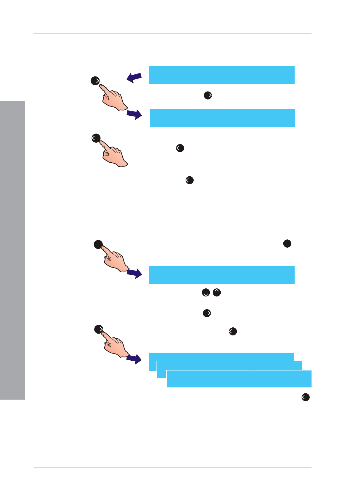
ID50 Series Panel - Installation, Commissioning & Configuration Manual
5.5.1.1 Language
1 When the Panel Options menu option is selected the
Language edit screen is displayed.
[Setup] Language = English
6
> : Change ¦ : More < : Exit
2 Press the ‘6’ button to step through the available
languages.
[Setup] Språk = Svenska
> : Change ¦ : Mer < : Exit
4
3 When the desired language is displayed, press the
‘4’ button to return to the Setup menu screen. The
language selection is saved automatically.
4 Make another Panel Options menu selection or press
the ‘4’ button to return to the Commissioning Menu.
5.5.1.2 Date Format
This option is used to select one of three available date
formats for display on the LCD. The options available are
dd/mm/yyyy, mm/dd/yyyy or yyyy/mm/dd. To change the date
format:
1
1 From the Setup menu screen, press the ‘1’ button
on the numeric keypad to display the Panel Options
menu. Initially the Language screen is displayed:
[Setup] Language = English
> : Change ¦ : More < : Exit
Press the ‘2/8’ buttons to scroll through the Panel
Options until the Date Format screen is displayed.
Configuration Mode
6
[Setup] Date Format = mm/dd/yyyy
> : Change ¦ : More < : Exit
997-263-000-11, Issue 11
January 2010
2 Press the ‘6’ button to step through the alternative
Date Format settings. When the desired format is
displayed, press the ‘4’ button to return to the Setup
menu screen. The date format selection is saved
automatically.
[Setup] Date Format = yyyy/mm/dd
> : Change ¦ : More < : Exit
[Setup] Date Format = dd/mm/yyyy
> : Change ¦ : More < : Exit
3 Make another Setup menu selection or press the ‘4’
button once more to return to the Commissioning Menu.
40
Page 45
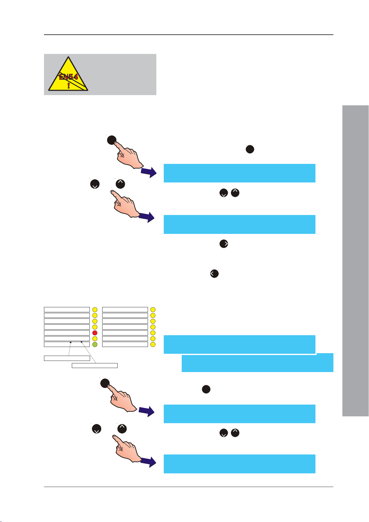
ID50 Series Panel - Installation, Commissioning & Configuration Manual
5.5.1.3 Control Keys Access Level
EN54-2 : 7.6.1, 7.8, 8.7.1,
9.1.2
Ensure EN54 compliance
for access to controls.
1
or
82
EN54-2 requires the following access to controls:
Level 2: Reset (EN54-2 Clauses 7.6.1 & 8.7.1)
Silence Sounders (EN54-2 Clause 7.8)
Extend Delays (EN54-2 Clause 9.1.2)
Level 1: End Delays (or MCP) (EN54-2 Clause 7.11d).
The Control Keys option allows the access level at which
the panel control keys can be operated to be changed.
To select the required access level:
1 From the Setup menu screen, using the numeric
keypad press the ‘1’ button to enter the Panel
Options menu. The Language screen is displayed first.
[Setup] Language = English
> : Change ¦ : More < : Exit
2 Press the ‘2/8’ buttons to step through the Panel
Options menus until the Control Keys screen is
displayed.
[Setup] Control Keys Access Level = 2
> : Change ¦ : More < : Exit
DISABLEMENT
TEST
DELAYS ACTIVE
FIRE OUTPUT: FAULT / DISABLED
FIRE OUTPUT ACTIVE
POWER
PLANT ALARM
FAULTO/P: FAULT / DISABLED
POWER SUPPLY FAULT
FAULT
EARTH FAULT
SYSTEM FAULT
SOUNDER: FAULT/ DISABLED
PRE- ALARM
FIRE CONTROL O/P: FAULT/ DISABLED
1
3 Press the ‘6’ button to change the setting to level 1
(no passcode) or level 2 (user passcode). The default
access level is level 2.
4 Press ‘4’ to return to the Setup menu screen. All
changes will be saved on exiting.
5.5.1.4 LED 1H Mode
The default function for this LED is PLANT ALARM. This option
allows this LED on panels with the new 5-button membrane
to be configured as FAULT O/P: FAULT/DISABLED.
[S1 Setup] 1: Panel Options
2: Site Details 3: Device Options ¦ : More
[S1 Setup] 4: Peripheral Options
5: Day / Night Settings ¦ : More
1 From the Setup menu, using the numeric keypad press
the ‘1’ button to enter the Panel Options menu. The
Language screen is displayed first.
[Setup] Language = English
> : Change ¦ : More < : Exit
Configuration Mode
or
2
8
2 Press the ‘2/8’ buttons to step through the Panel
Options menus until the LED 1H Mode screen is
displayed.
[Setup] LED 1H = Plant Alarm
> : Change ¦ : More < : Exit
41
997-263-000-11, Issue 11
January 2010
Page 46
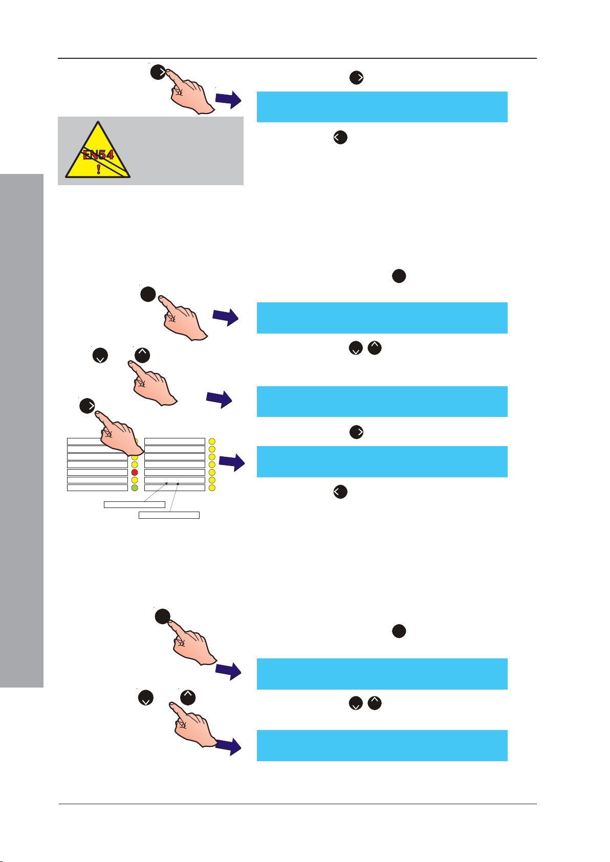
ID50 Series Panel - Installation, Commissioning & Configuration Manual
6
EN54-2 : 8.2.4 g)
If a fault-routing output is
configured, a fault-routing
output transmission circuit
fault indication must be
provided.
1
or
82
3 Press the ‘6’ button to toggle the LED function.
[Setup] LED 1H = Fault Output: F/D
> : Change ¦ : More < : Exit
4 Press ‘
4
’ to return to the Setup menu screen. All
changes will be saved on exiting.
5.5.1.5 LED 2C Mode
The default function of this LED is PRE-ALARM. This
option allows the LED to be configured as SOUNDERS
SILENCED.
1 From the Setup menu screen, using the numeric
keypad press the ‘1’ button to enter the Panel
Options menu. The Language screen is displayed first.
[Setup] Language = English
> : Change ¦ : More < : Exit
2 Press the ‘2/8’ buttons to step through the Panel
Options menus until the LED 2C Mode screen is
displayed.
[Setup] LED 2C = Pre-alarm
6
DISABLEMENT
TEST
DELAYSACTIVE
FIRE OUTPUT: FAULT / DISABLED
FIRE OUTPUT ACTIVE
PLANT ALARM
POWER
POWER SUPPLY FAULT
SOUNDER: FAULT/ DISABLED
FIRE CONTROL O/P: FAULT/ DISABLED
PRE- ALARM
SOUNDERS SILENCED
FAULT
EARTH FAULT
SYSTEM FAULT
> : Change ¦ : More < : Exit
[Setup] LED 2C = Sounders Silenced
> : Change ¦ : More < : Exit
5.5.1.6 Un-mute
Configuration Mode
1
[Setup] Language = English
> : Change ¦ : More < : Exit
or
2
8
3 Press the ‘6’ button to toggle the LED function.
4 Press ‘4’ to return to the Setup menu screen. All
changes will be saved on exiting.
This option is used to control how new alarms un-mute
the internal buzzer, i.e. new alarms occurring in zones
not previously in alarm or for any new device going into
alarm. To set the desired un-mute option:
1 From the Setup menu screen, using the numeric
keypad press the ‘1’ button to enter the Panel
Options menu. The Language screen is displayed first.
2 Press the ‘2/8’ buttons to step through the Panel
Options menus until the Un-mute screen is displayed.
997-263-000-11, Issue 11
January 2010
[Setup] Un-mute = On new zone alarm
> : Change ¦ : More < : Exit
42
Page 47
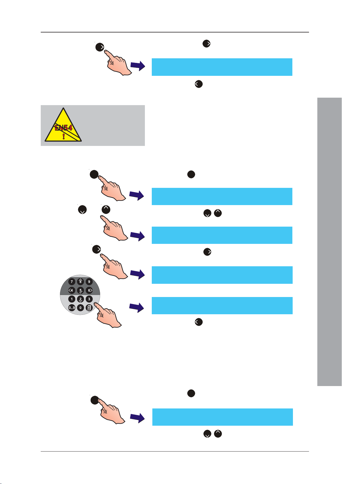
ID50 Series Panel - Installation, Commissioning & Configuration Manual
6
6
3 Press the ‘
alarm’ and ‘On new point alarm’ input options.
[Setup] Un-mute = On new point alarm
> : Change ¦ : More < : Exit
’ button to toggle between ‘On new zone
EN54-4: 5.4
Mains fail delay
MUST not exceed 30
minutes.
1
or
2
8
6
4 Press ‘
changes will be saved on exiting.
4
’ to return to the Setup menu screen. All
5.5.1.7 Mains Fault Delay
By default, a mains fault is indicated within 10 seconds.
This option allows the delay to be extended up to 60
minutes in one minute increments. A fault indication
delay of more than 30 secs does not comply with
EN54 (see information at left). To configure a fault output
delay, proceed as follows:
1 From the Setup menu, using the numeric keypad press
the ‘1’ button to enter the Panel Options menu.The
Language screen is displayed first.
[Setup] Language = English
> : Change ¦ : More < : Exit
2 Press the ‘2/8’ buttons to step through the Panel
Options until the Mains Fault Delay screen is displayed.
[Setup] Mains Fault Delay = 10
> : Change ¦ : More < : Exit
3 Press the ‘6’ button to change the delay time to the
required setting:
[Setup] Mains Fault Delay = 10 Enter new value _ : Confirm < : Cancel
4 Use the numeric keypad to enter the new value:
[Setup] Mains Fault Delay = 20
> : Change ¦ : More < : Exit
5 Press ‘4’ to return to the Setup menu screen. All
changes will be saved on exiting.’
Configuration Mode
5.5.1.8 Diagnostic Mode
The Diagnostic Mode option allows extended fault and
fire reporting and determines whether events are
suppressed until confirmed. To enable Diagnostic Mode:
1 From the Setup menu, using the numeric keypad press
the ‘1’ button to enter the Panel Options menu.The
1
[Setup] Language = English
> : Change ¦ : More < : Exit
Language screen is displayed first.
2 Press the ‘2/8’ buttons to step through the Panel
Options until the Diagnostic Mode menu is displayed.
43
997-263-000-11, Issue 11
January 2010
Page 48
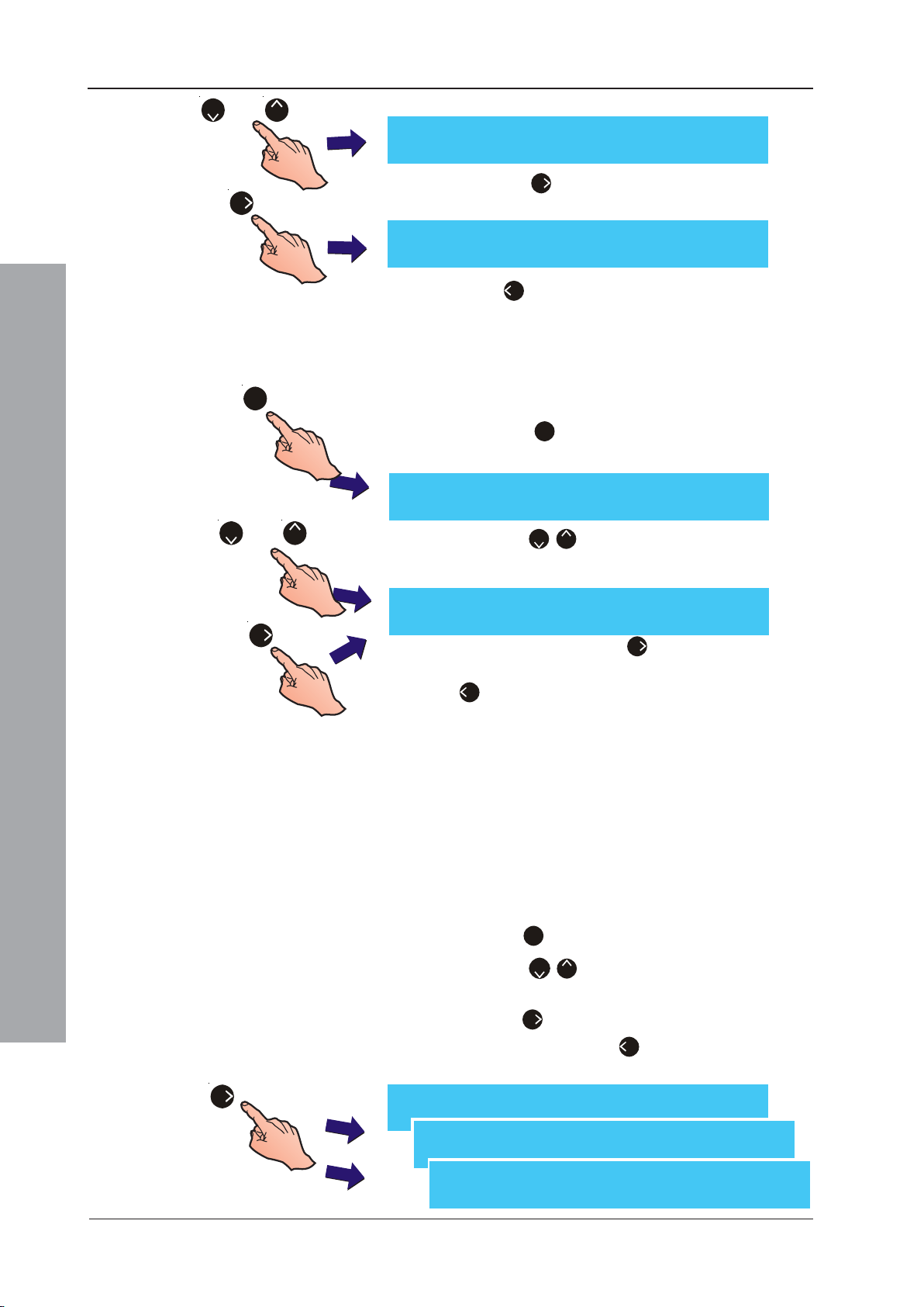
ID50 Series Panel - Installation, Commissioning & Configuration Manual
or
2
8
[Setup] Diagnostic Mode = ON
> : Change ¦ : More < : Exit
3 Press the ‘6’ button to select the required setting,
6
[Setup] Diagnostic Mode = OFF
> : Change ¦ : More < : Exit
either ON or OFF.
4 Press ‘4’ to return to the Setup menu. All changes
will be saved on exiting this menu.
5.5.1.9 VdS Compatibility
The VdS Compatibility option must be set to ‘Disabled’.
1
or
2
8
1 From the Setup menu, using the numeric keypad
press the ‘1’ button to enter the Panel Options
menu.The Language screen is displayed first.
[Setup] Language = English
> : Change ¦ : More < : Exit
2 Press the ‘2/8’ buttons to step through the Panel
Options until the ‘VdS Compatibility’ menu is displayed.
[Setup] VdS Compatibility = DISABLED
> : Change ¦ : More < : Exit
6
5.5.1.10Automatic Resound
Configuration Mode
3 If necessary, press the ‘6’ button to change VdS
Compatibility from ‘ENABLED’ to ‘DISABLED’. Press
‘4’ to return to the Setup menu. All changes will be
saved on exiting this menu.
By default, after the panel has received a fire event and
the sounders have been silenced using the SILENCE/
RESOUND pushbutton a new fire event, in ANY zone,
will re-activate the sounder outputs. This option allows
the configuration of sounder outputs either to re-activate
with NEW zone-in-fire events or ignore any new fire
events after the sounders have been silenced.
1 From the Setup menu, using the numeric keypad
press the ‘1’ button to enter the Panel Options menu.
2 Press the ‘2/8’ buttons to step through the Panel
Options until the ‘Automatic Resound’ menu is displayed.
3 Press the ‘6’ button to select the required setting, either
NEW ZONE or NO. Press ‘4’ to return to the Setup menu.
All changes will be saved on exiting this menu.
6
997-263-000-11, Issue 11
January 2010
[Setup] Automatic Resound = ANY ZONE
> : Change ¦ : More < : Exit
[Setup] Automatic Resound = NEW ZONE
> : Change ¦ : More < : Exit
[Setup] Automatic Resound = NO
> : Change ¦ : More < : Exit
44
Page 49
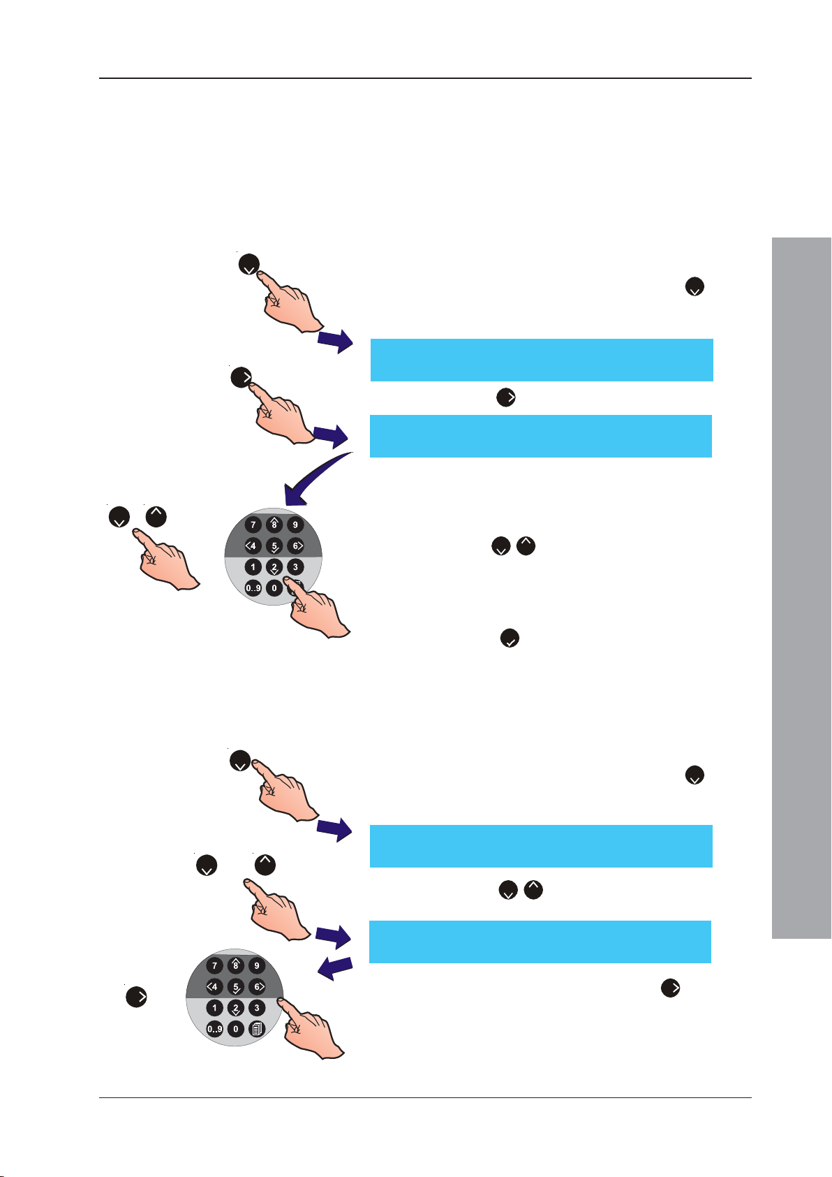
ID50 Series Panel - Installation, Commissioning & Configuration Manual
5.5.2 Site Details
The Site Details Setup option enables site name and
service contractor information to be displayed on the
panel. With ID60 panels there is an option for configuring
a service due date (refer to Appendix 2 for details).
5.5.2.1 Service Phone Number
This option allows a service contact phone number to be
2
6
displayed with fault messages. To enter or change the number:
1 From the Setup menu screen, press the ‘2’ button
on the numeric keypad to select the Site Details option.
The Service Phone Number option is displayed:
[Setup] Phone = < blank/existing text >
> : Change ¦ : More < : Exit
2 Press the ‘6’ button to enter the text editing menu.
[]¦ : Char : Done
> : Next < : Previous u1:Delete u3:Insert
3 The existing 20-characters of text are shown on the
upper line (for new panels this area is blank). The current
82
/
or
cursor position is indicated by a flashing character. Enter
the required telephone number via the numeric keypad
or use the ‘2/8’ buttons to scroll through the available
alphanumeric characters.
Note: For further information on how to edit text, refer to
Section 5.8, Zone Texts.
4 Press the ‘5’ button to confirm and return to the
Setup menu screen.
5.5.2.2 Site Name
The Site Name option allows the entry of up to
20 characters to replace the ‘Status: NORMAL’ display
2
or
2
8
on the LCD. To edit/change the characters:
1 From the Setup menu screen, press the ‘2’ button
on the numeric keypad to select the Site Details option.
The Service Phone Number option is displayed first:
[Setup] Phone = < blank/existing text >
> : Change ¦ : More < : Exit
Configuration Mode
2 Press the ‘2/8’ buttons to display the Site Name
screen.
[]¦ : Char : Done
> : Next < : Previous u1:Delete u3:Insert
and
6
3 To edit/change the site name, press the ‘6’ button. The
LCD display is replaced by a text editing menu with the
existing 20-characters of text on the upper line. The current
cursor position is indicated by a flashing character.
Note: For further information on how to edit text, refer to
Section 5.8, Zone Texts.
45
997-263-000-11, Issue 11
January 2010
Page 50
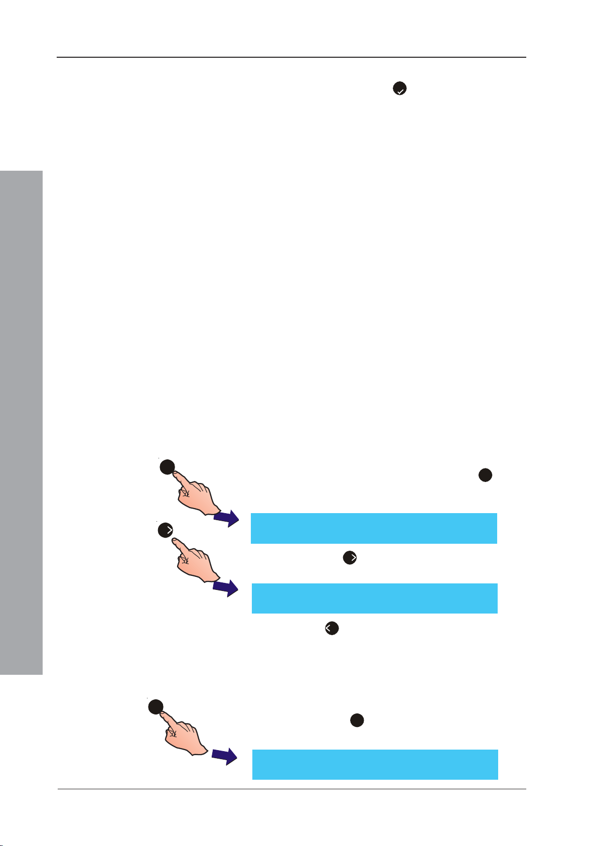
ID50 Series Panel - Installation, Commissioning & Configuration Manual
4 Using the appropriate buttons, edit the text then confirm
5
the new text using the ‘
the Setup menu screen. All changes are saved on exiting.
’ button. The LCD returns to
5.5.3 Device Options
Setup menu Device Options allows the configuration of
the following system inputs and outputs:
a. Device blinking
b. Output Pulse ON/OFF ratio
c. Auto High Test
d. Digital Input 1
e. Maximum LEDs ON
f. Day Mode Sensitivity
g. Weekend Night Sensitivity
h. Extinguishing System delay and soak timers
i. Extinguishing System Hold Switch operation
j. Transmission Device (VdS only)
k. Fireman’s Work Panel
l. FWP2 Output Circuit (VdS only)
m. Double Address Detection
n. TD/ES Disablement at Access Level 2
5.5.3.1 Device Blinking
3
Configuration Mode
6
[Setup] Device Blinking = ON
> : Change ¦ : More < : Exit
[Setup] Device Blinking = OFF
> : Change ¦ : More < : Exit
5.5.3.2 Output Pulse On/Off Ratio
3
The Device Blinking option configures the LED’s of
sensors and modules on the SLC Loop to blink or not
when polled. To configure this option:
1 From the Setup menu screen, press the ‘3’ button
on the numeric keypad to enter the Device Options
menu. The Device Blinking screen is displayed first.
2 Press the ‘6’ button to select the required setting,
either ON or OFF.
3 Press ‘4’ to return to the Setup menu screen.
The Pulse On/Off Ratio option is used to set the sounder
output pulse ratio to either 1/1 or 4/1. To configure the ratio:
1 From the Setup menu screen, use the numeric keypad
and press the ‘3’ button to enter the Device Options menu.
The Device blinking screen is displayed first.
997-263-000-11, Issue 11
January 2010
[Setup] Device Blinking = ON
> : Change ¦ : More < : Exit
46
Page 51
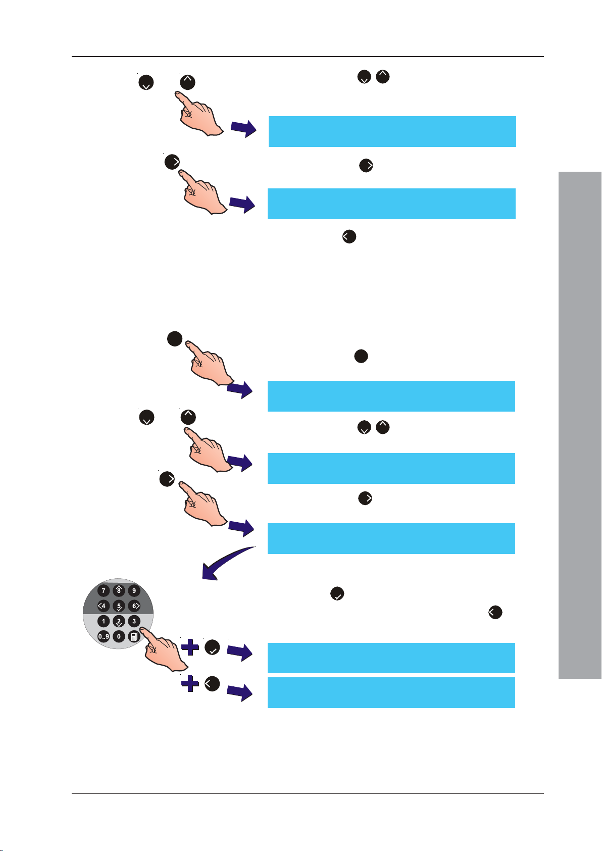
ID50 Series Panel - Installation, Commissioning & Configuration Manual
2/8
or
2
8
2 Press the ‘
’ buttons to step through the Device
Options until the Pulse On/Off Ratio menu is
displayed.
[Setup] Pulse On/Off ratio = 1/1
> : Change ¦ : More < : Exit
6
3 Press the ‘
6
’ button to change the required setting
to either 1/1 or 4/1.
[Setup] Pulse On/Off ratio = 4/1
> : Change ¦ : More < : Exit
4 Press ‘4’ to return to the Setup menu screen.
5.5.3.3 Auto High Test
The Auto High Test setup menu configures the panel to
test each device on the loop at a specified time. The test
checks that each device is able to produce an alarm
reading at the panel. To configure the Auto High Test:
3
or
2
8
1 From the Setup menu screen, using the numeric keypad
press the ‘3’ button to enter the Device Options menu.
The Device blinking screen is displayed first:
[Setup] Device Blinking = ON
> : Change ¦ : More < : Exit
2 Press the ‘2/8’ buttons to step through the Device
Options until the Auto High Test screen is displayed.
[Setup] Auto High Test = DISABLED
6
> : Change 1 : Disable ¦ : More < : Exit
3 Press the ‘6’ button to enter (edit) the time at which
Auto High Test will start.
[Setup] Auto High Test = DISABLED
Enter start time : -0:00 < : Cancel
Configuration Mode
4 Using the numeric keypad, enter an appropriate start time
in the 24-hour clock format and confirm the set time using
the ‘5’ button. The LCD automatically returns to the
Auto High Test screen. Alternatively, press ‘4’ to cancel
all changes and return to the Auto High Test screen.
5
[Setup] Auto High Test = 07:46
> : Change 1 : Disable ¦ : More < : Exit
4
[Setup] Auto High Test = DISABLED
> : Change 1 : Disable ¦ : More < : Exit
47
997-263-000-11, Issue 11
January 2010
Page 52
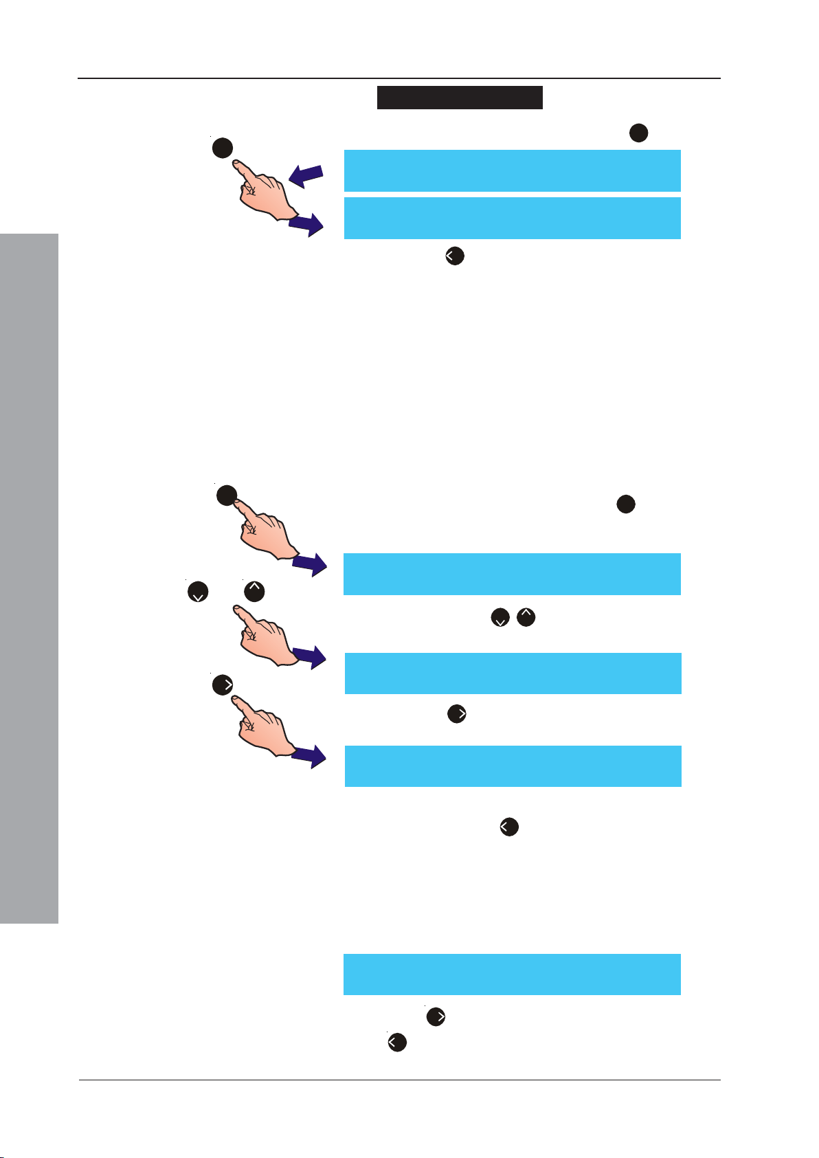
ID50 Series Panel - Installation, Commissioning & Configuration Manual
To disable this function
1 To disable Auto High Test, press the ‘1’ button:
1
[Setup] Auto High Test = 07:46
> : Change 1 : Disable ¦ : More < : Exit
[Setup] Auto High Test = DISABLED
> : Change 1 : Disable ¦ : More < : Exit
2 Press ‘4’ to return to the Setup menu screen.
5.5.3.4 Digital Input 1
Digital Input 1 can be configured as either Day Mode Start
or Class Change function.
When configured as Day Mode Start, activation from the
input during the Day Mode period starts/ends Day Mode
delays, depending on their current state.
When Class Change is selected outputs assigned to CBE
Rules that have Class Change configured will activate
when Digital Input 1 is operated.
3
[Setup] Device Blinking = ON
or
2
8
6
> : Change ¦ : More < : Exit
[Setup] Digital Input 1 = Day Mode Start
> : Change ¦ : More < : Exit
Configuration Mode
[Setup] Digital Input 1 = Class Change
> : Change ¦ : More < : Exit
5.5.3.5 Maximum LEDs ON
To configure Digital Input 1:
1 Using the numeric keypad, press ‘3’ at the Setup
menu screen to enter the Device Options screen. The
Device blinking screen is displayed first.
2 Press either ‘2/8’ to step through the Device
Options until the Digital Input 1 menu is displayed.
3 Press ‘6’ to toggle between Day Mode Start and
Class Change.
4 With the required configuration of Digital Input 1
displayed, press ‘4’ to return to the Setup menu screen.
997-263-000-11, Issue 11
January 2010
The maximum number of LEDs turned on in alarm or
fault conditions can be set to 10 or 2. Fire takes priority;
a fault LED will be turned off to allow a fire LED to be
turned on if the LED maximum has been reached.
[Setup] Max. LEDs ON = 10
> : Change ¦ : More < : Exit
Press ‘6’ to toggle between 10 (default) and 2 or press
‘4’ to return to the Setup menu screen.
48
Page 53
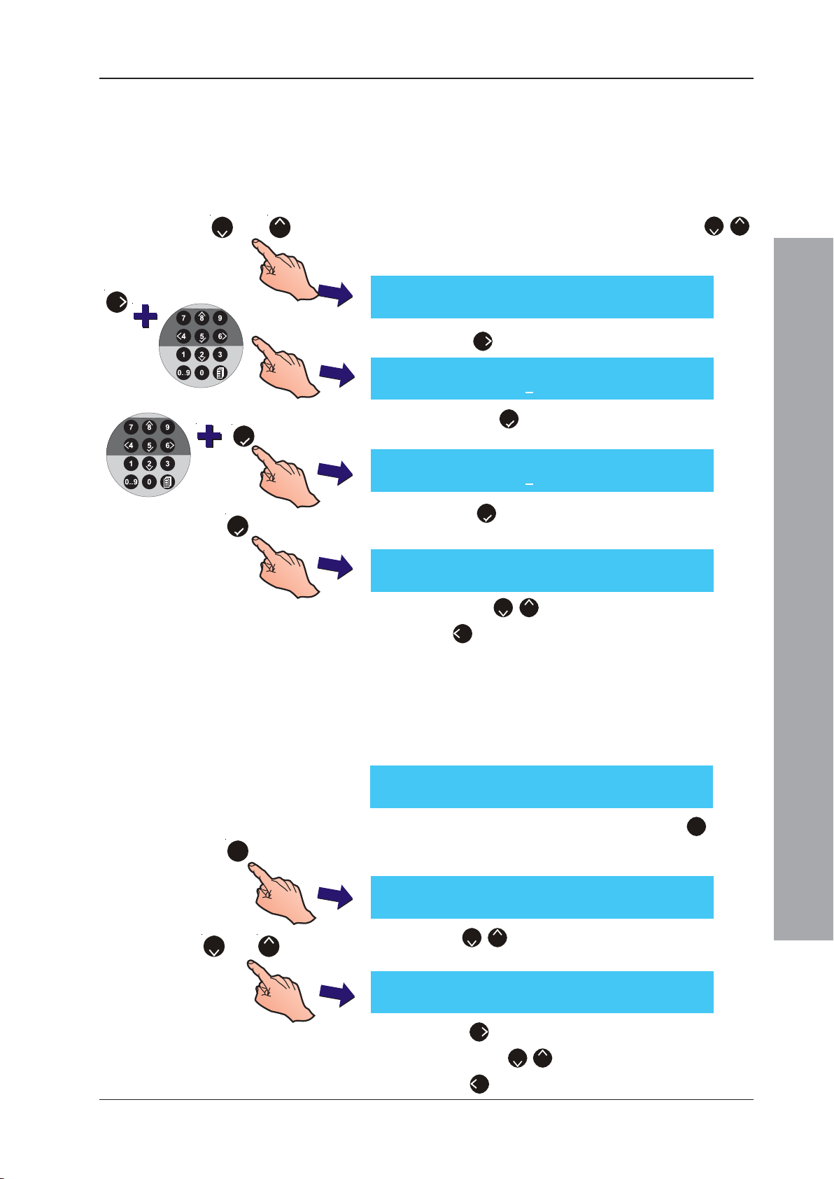
ID50 Series Panel - Installation, Commissioning & Configuration Manual
5.5.3.6 Day Mode Sensitivity
This option allows a change in sensor sensitivity to be set
during the same period each day (including weekends unless
Weekend Night Mode is enabled). Refer to Section 5.6.1.2
Sensor Sensitivity Setting for day mode sensitivity setting.
Day mode start and end times need to be specified as follows:
or
82
6
5
5
1 From the Device options menu, press either ‘2/8’
to step through the Device Options until the Day Mode
Sensitivity screen is displayed.
[Setup] Day Mode Sensitivity = DISABLED
> : Change 1: Disable ¦ : More < : Exit
2 Press ‘6’ to enter a start time (using the 24hr clock):
[Setup] Day Mode Sensitivity = DISABLED
Enter Start time: 08:00 < : Cancel
3 Press the ‘5’ button to confirm the start time. You
are now prompted to enter an end time:
[Setup] Day Mode Sensitivity = DISABLED
Enter Finish time: 17:00 < : Cancel
Press the ‘5’ button to confirm the finish time. The day
mode start and end times are now displayed:
[Setup] Day Mode Sensitivity = 08:00 ->17:00
> : Change 1: Disable ¦ : More < : Exit
Press either ‘2/8’ to select another device option or
press ‘4’ to return to the Setup menu screen.
5.5.3.7 Weekend Night Sensitivity
If Weekend Night Sensitivity is enabled, the panel
disregards the Day Mode Sensitivity period on the two
days of the week that coincide with the weekend. To set
this mode active:
[Setup] 1: Panel Options
2: Site Details 3: Device Options ¦ : More
1 From the Setup menu screen, press the ‘3’ button
3
[Setup] Device Blinking = ON
> : Change ¦ : More < : Exit
or
2
8
[Setup] Weekend night Sens. = ENABLED
> : Change ¦ : More < : Exit
on the numeric keypad to enter the Device Options
menu. The Device Blinking screen is displayed first.
2 Use ‘2/8’ to scroll through the device options until
Weekend night Sensitivity is displayed:
3 Press ‘6’ to toggle between ENABLED and DISABLED.
Configuration Mode
Press either ‘2/8’ to select another device option or
press ‘4’ to return to the Setup menu screen.
49
997-263-000-11, Issue 11
January 2010
Page 54
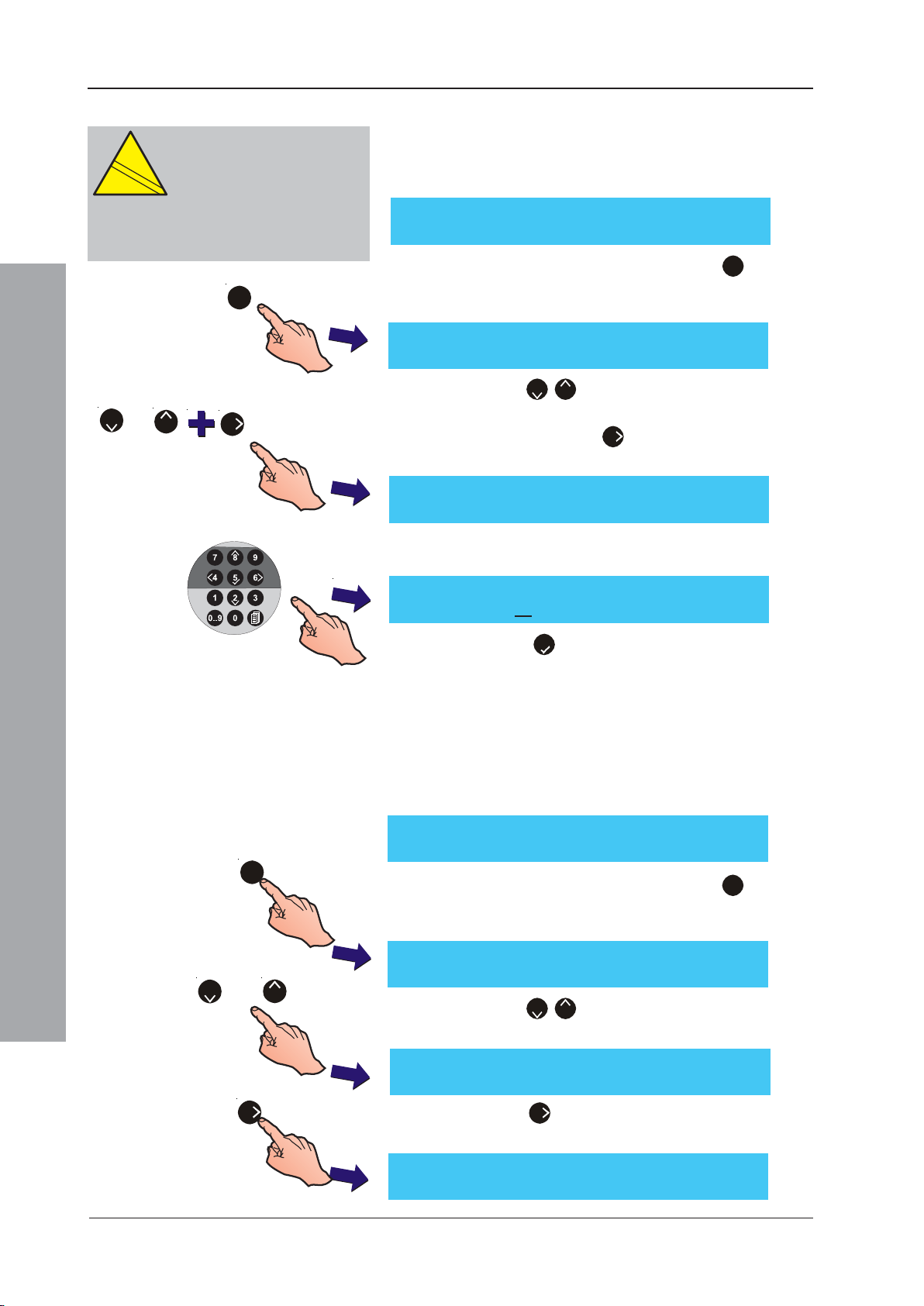
ID50 Series Panel - Installation, Commissioning & Configuration Manual
EN
12094-1
!
5.5.3.8 Extinguishing System Delay
CAUTION:
12094-1
!
with EN 12094-1.
This product is not compliant
EN
Fire extinguishing installations in
Europe are required to be certified as
compliant to this standard.
3
or
2
8
6
The extinguishing system delay allows an evacuation period
of up to 180 seconds to be entered (default 60 secs, minimum
of 10 secs). To configure the delay, proceed as follows:
[Setup] 1: Panel Options
2: Site Details 3: Device Options ¦ : More
1 From the Setup menu screen, press the ‘3’ button on
the numeric keypad to enter the Device Options menu.
The Device blinking screen is displayed first.
[Setup] Device Blinking = ON
> : Change ¦ : More < : Exit
2 Press the ‘2/8’ buttons to step through the Device
Options until the Ext. System Delay screen is
displayed. Press the ‘6’ button to change the delay
time. The display then prompts you for the new value:
[Setup] Ext. System Delay = 60 Seconds
Enter new value __ : Confirm < : Cancel
3 Enter the required delay time using the numeric
buttons, e.g. 30 secs:
[Setup] Ext. System Delay = 60 Seconds
Enter new value 30 : Confirm < : Cancel
5.5.3.9 Extinguishing System Soak
Configuration Mode
3
or
2
8
[S1 Setup] 1: Panel Options
[Setup] Device Blinking = ON
> : Change ¦ : More < : Exit
4 Press the ‘5’ button to confirm and return to the
Setup menu screen.
To specify for how long the extinguishing system operates
after being turned on:
Note: The timer will only be triggered by CBE rules that
have the Soak Timer Enable activated.
2: Site Details 3: Device Options ¦ : More
1 From the Setup menu screen, press the ‘3’ button on
the numeric keypad to enter the Device Options menu.
The Device blinking screen is displayed first.
2 Press the ‘2/8’ buttons to step through the Device
Options to display the Ext. System Soak screen.
[Setup] Ext. System Soak = 0 Seconds
> : Change ¦ : More < : Exit
6
997-263-000-11, Issue 11
January 2010
3 Press the ‘6’ button. The display then prompts you
for the new value:
[Setup] Ext. System Soak = 0 Seconds
Enter new value __ : Confirm < : Cancel
50
Page 55
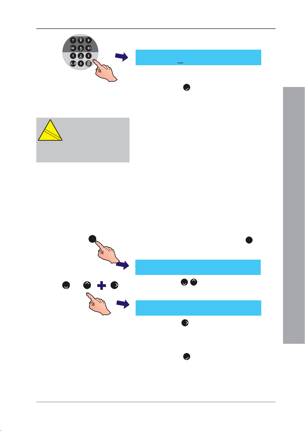
ID50 Series Panel - Installation, Commissioning & Configuration Manual
EN
12094-1
!
4 Enter a delay time using the numeric buttons, between
0 and 999 secs, e.g. 90 secs:
[Setup] Ext. System Soak = 0 Seconds
Enter new value 90 : Confirm < : Cancel
Note: Entering a value of ‘0’ means that the output, after
switching ON, is not switched OFF.
5 Press the ‘5’ button to confirm and return to the
Setup menu screen.
5.5.3.10 Hold Switch Operation
CAUTION:
12094-1
!
with EN 12094-1.
This product is not compliant
EN
Fire extinguishing installations in
Europe are required to be certified as
compliant to this standard.
3
AUX modules, configured as one of four Hold Switch
categories, can be used to affect the Extinguishing
System Delay timer function. The four categories are:
AHJ - While this input is active, the Extinguishing System
Delay timer is reset to the configured value and paused.
NYC - While this input is active, the Extinguishing
System Delay timer is reset to the configured value
plus 90 secs and paused.
ULI - While active, the Extinguishing System Delay
timer continues to count down but pauses at 10 secs
before release.
IRI - Hold switch activity is ignored if two or more
zones associated with CBE rules with a category of
‘Extinguishing System’ are in alarm. Otherwise
operation is the same as type ULI.
Note: Only one of the above Hold Switch input types may
be used per panel.
1 From the Setup menu screen, press the ‘3’ button on
the numeric keypad to enter the Device Options menu.
The Device blinking screen is displayed first.
[Setup] Device Blinking = ON
> : Change ¦ : More < : Exit
Configuration Mode
or
2 6
8
2 Press the ‘2/8’ buttons to step through the Device
Options until the LCD shows the Hold Switch
Operation menu.
[Setup] Hold Switch Operation = AHJ
> : Change ¦ : More < : Exit
3 Press the ‘6’ button to select alternative settings of
NYC, ULI or IRI, as required. Changing the setting
saves the change automatically.
Note: The default selection is AHJ.
4 Press the ‘5’ button to confirm and return to the
Setup menu screen.
5.5.3.11 Transmission Device
The Transmission Device activates in response to an
alarm condition. The ‘Transmission Device’ menu enables
the configuration of either a continuous or a 6 second
51
997-263-000-11, Issue 11
January 2010
Page 56
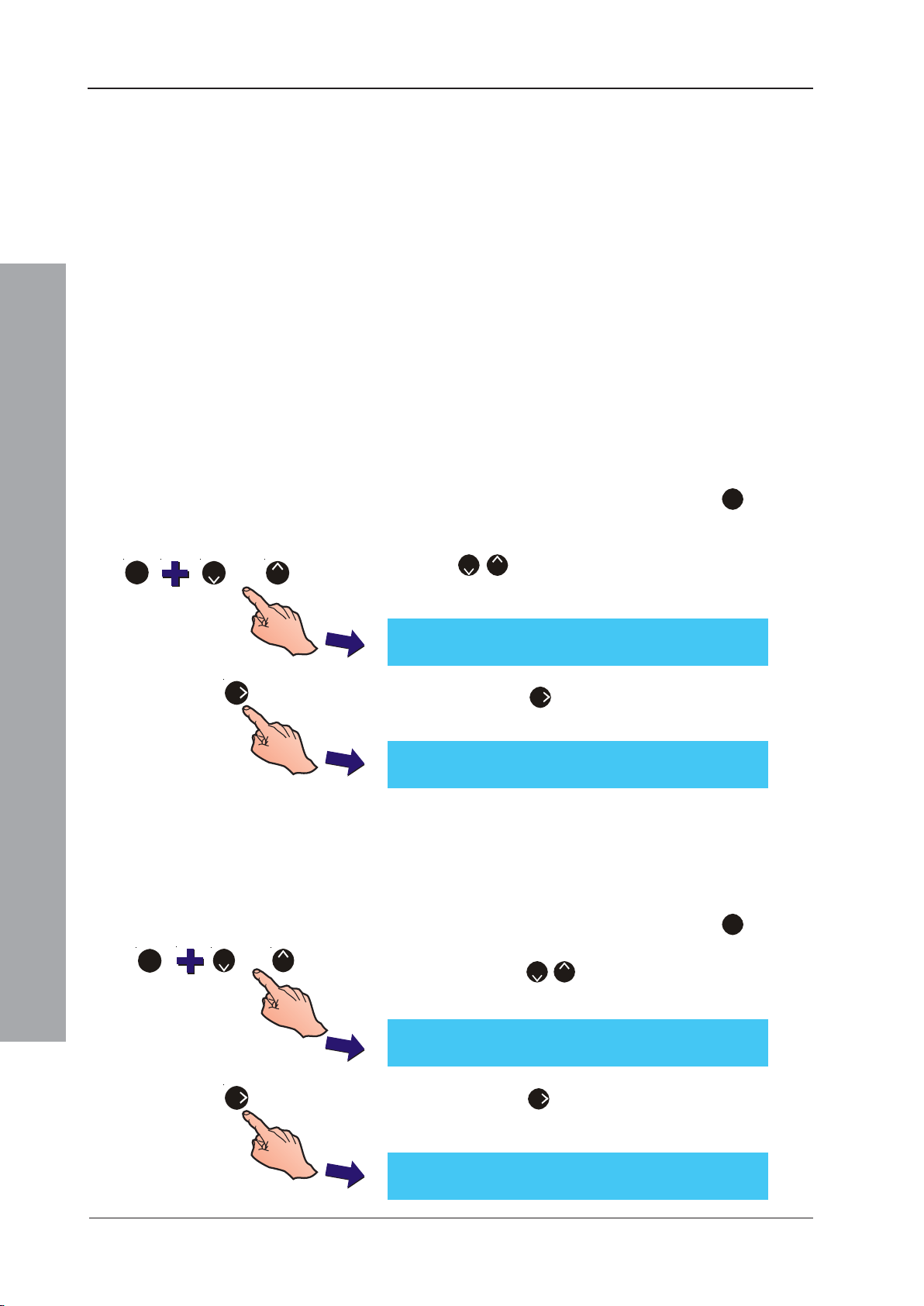
ID50 Series Panel - Installation, Commissioning & Configuration Manual
pulse response. This feature is required for VdScompliant operation only.
5.5.3.12 Fireman’s Work Panel
This option allows the panel to be configured to work with
a German or Swiss Fireman’s Work Panel (FWP).
5.5.3.13 FWP 2 Output Activation
This option is used to control the way the Transmission
Device-triggered output, FWP 2, is activated by the
Fireman’s Work panel (FWP).
This feature is required for VdS-compliant operation only.
5.5.3.14 Double Address Detection
Automatic detection of devices with the same address is
the default condition. If this facility is not required it may
be turned off using this menu option.
1 From the Setup menu screen, press the ‘3’ button on
the numeric keypad to enter the Device Options menu.
The Device blinking screen is displayed first. Press the
3
or
2
8
[Setup] Double Address Detection = ON
> : Change ¦ : More < : Exit
‘2/8’ buttons to step through the Device Options
until the LCD shows the Double Address Detection
menu.
6
[Setup] Double Address Detection = OFF
> : Change ¦ : More < : Exit
Configuration Mode
or
3
2
6
8
5.5.3.15 TD/ES Disablement at Access Level 2
[Setup] TD/ES Auto Disable = No
> : Change ¦ : More < : Exit
2 Press the 6 button to deactivate double address
detection. Press this button again to cancel.
The Transmission Device (TD) and Extinguishing System
(ES) outputs can be configured for automatic disablement
at access level 2 via the panel keyswitch or cover-off switch.
1 From the Setup menu screen, press the ‘3’ button on
the numeric keypad to enter the Device Options menu.
Press the ‘2/8’ buttons to step through the Device
Options until the LCD shows the TD/ES Auto Disable menu.
2 Press the 6 button to select the TD/ES automatic
disbablement function. Press this button again to cancel.
997-263-000-11, Issue 11
January 2010
[Setup] TD/ES Auto Disable = Yes
> : Change ¦ : More < : Exit
52
Page 57
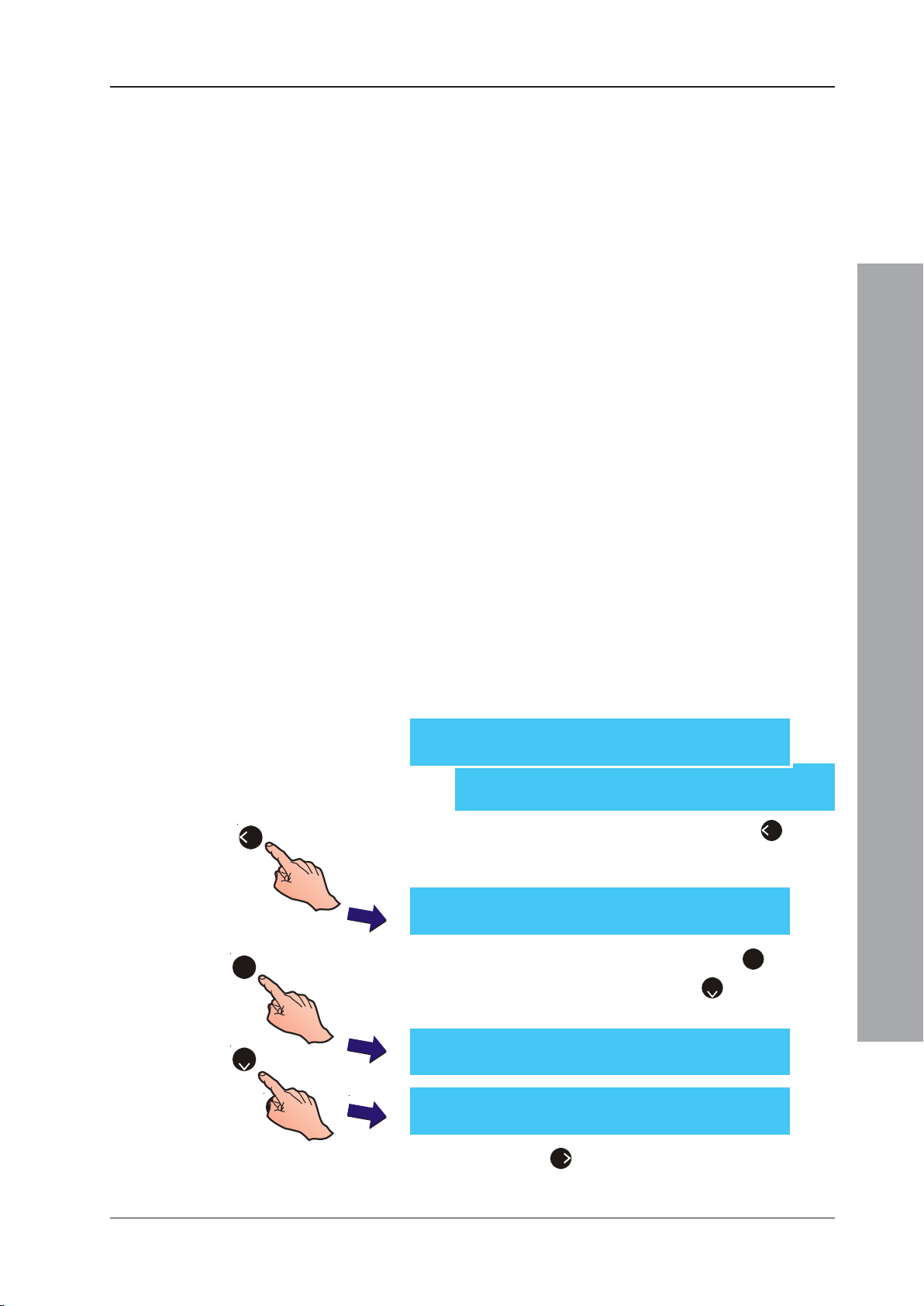
ID50 Series Panel - Installation, Commissioning & Configuration Manual
5.5.4 Peripheral Options
This option is used for setting up the connection of
peripheral equipment via the RS232 and RS485
communication ports.
Select either RS485 or RS232 and then one of the specific
equipment options available.
If RS485 is selected, the repeater protocol options
available are:
a. NOTIFIER
b. ARP50/RP50
c. BFT/LLT (for use with Swedish repeaters only)
d. DISABLED
Refer to Section 5.5.4.3 for further details on repeater
protocol selection.
If RS232 is selected, the protocol options available are:
a. PRINTER
b. THIRD PARTY
c. GSM MODEM (for use with GSM Communications
Module)
Refer to Section 5.5.4.6 for further details on RS232
protocol selection.
5.5.4.1 Communications Port Selection
The Communications Port selection is made through the
Peripheral Options screen.
[S1 Setup] 1: Panel Options
2: Site Details 3: Device Options ¦ : More
[S1 Setup] 4: Peripheral Options
5: Day / Night Settings ¦ : More
4
1
1 From the Setup menu screen, press the ‘4’ button
on the numeric keypad to display the Communications
Port Selection screen:
[S1 Peripheral Options] 1: RS485
2:RS232
2 Using the numeric keypad, press the ‘1’ button to
select RS485 port options or the ‘2’ button to select
RS232 port options:
Configuration Mode
or
[Setup] RS485 Protocol = NOTIFIER
2
2
> : Change ¦ : More < : Exit
[Setup] RS232 Protocol = PRINTER
> : Change ¦ : More < : Exit
3 Press the ‘6’ button to select an alternative RS485
or RS232 protocol option (refer to Sections 5.5.4.3
and 5.5.4.6 for further details).
53
997-263-000-11, Issue 11
January 2010
Page 58
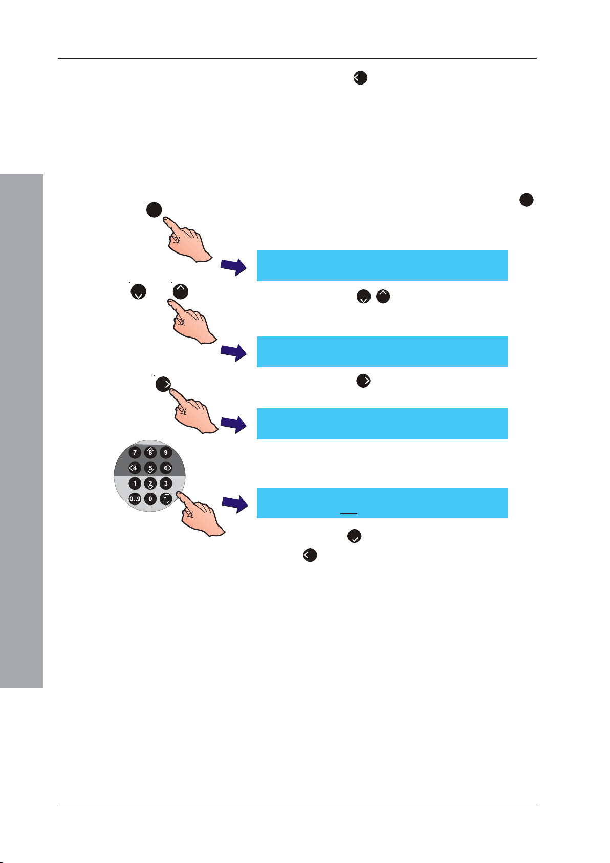
ID50 Series Panel - Installation, Commissioning & Configuration Manual
4
4 Press the ‘
screen.
’ button to return to the Setup menu
5.5.4.2 Number of Repeaters
The Number of Repeaters menu allows the quantity of
repeaters connected to the RS485 Communications Link
to be entered. The panel displays a fault if this quantity
does not equal the number of repeaters connected. To
enter the number:
1
or
2
8
6
1 From the Peripheral Options screen, press the ‘1’
button on the numeric keypad to select the RS485
Communications port option. The RS485 Protocol
setup screen is displayed:
[Setup] RS485 Protocol = NOTIFIER
> : Change ¦ : More < : Exit
2 Press the ‘2/8’ buttons to step through the
Peripheral Options until the Number of Repeaters
menu is displayed.
[Setup] No. of Repeaters = 0
> : Change ¦ : More < : Exit
3 Press the ‘6’ button to enable the number or
repeaters to be entered.
[Setup] No. of Repeaters = 0
Enter new value ____ : Confirm < : Cancel
4 Enter the required number using the numeric buttons;
for example if entering a value of 10, first press ‘1’,
then ‘0’.
[Setup] No. of Repeaters = 0
Enter new value 1 0 : Confirm < : Cancel
Configuration Mode
5.5.4.3 RS485 Protocol
997-263-000-11, Issue 11
January 2010
5 Press the ‘5’ button to confirm the selection or press
‘4’ repeatedly to cancel and return to the Setup menu
screen.
This option is used to select one of two available protocol
formats when repeaters are connected to the panel via
the RS485 communications link. The options available are:
a. NOTIFIER
b. ARP50/RP50.
The NOTIFIER protocol supports the IDR-2A and IDR-2P
Repeaters.
There are two additional options:
c. BFT/LLT repeater (Sweden only) communications link.
d. DISABLED - disables communication to any device
connected to the panel via the RS485 port.
54
Page 59
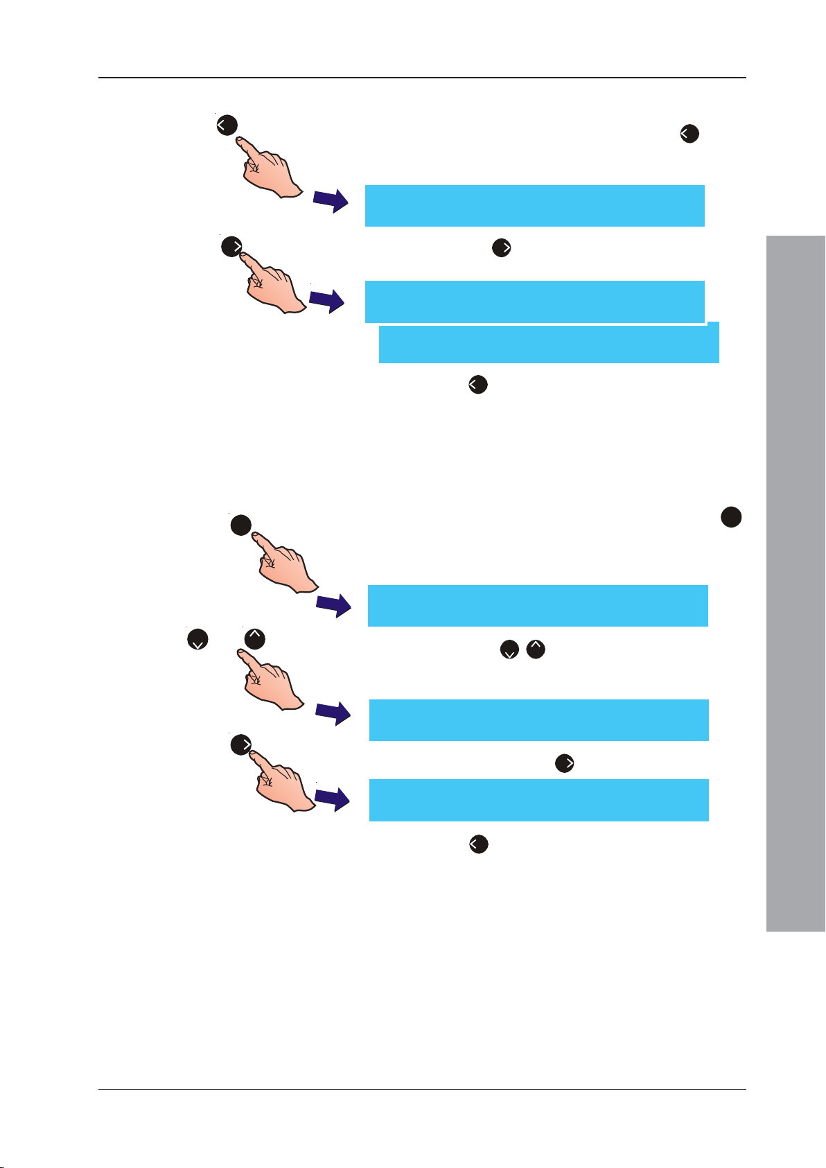
ID50 Series Panel - Installation, Commissioning & Configuration Manual
To change the RS485 Protocol:
4
6
1 From the Setup menu screen, press the ‘4’ button
on the numeric keypad to enter the Peripheral Options
screen. The RS485 Protocol screen is displayed:
[Setup] RS485 Protocol = NOTIFIER
> : Change ¦ : More < : Exit
2 Press the ‘6’ button repeatedly to step through the
alternative protocol settings.
[Setup] RS485 Protocol = THIRD PARTY
> : Change ¦ : More < : Exit
[Setup] RS485 Protocol = BFT/LLT
> : Change ¦ : More < : Exit
3 Press ‘4’ to return to the Peripherals menu screen.
5.5.4.4 Third Party Datalink Monitoring
This function is only selectable if Third Party was selected
at the RS485 Protocol screen. Monitoring of the third party
datalink can be enabled or disabled as follows:
1
1 From the Peripheral Options screen, press the ‘1’
button on the numeric keypad to select the RS485
Communications port option. The RS485 Protocol
setup screen is displayed:
or
[Setup] RS485 Protocol = THIRD PARTY
> : Change ¦ : More < : Exit
82
6
2 Press the ‘2/8’ buttons to scroll through the
Peripheral Options until the Data Link Monitoring
screen is displayed.
[Setup] Data Link Monitoring = ENABLED
> : Change ¦ : More < : Exit
3 If required, press the ‘6’ button to select DISABLED.
[Setup] Data Link Monitoring = DISABLED
> : Change ¦ : More < : Exit
4 Press ‘4’ to return to the Peripheral Options menu
screen.
Configuration Mode
55
997-263-000-11, Issue 11
January 2010
Page 60
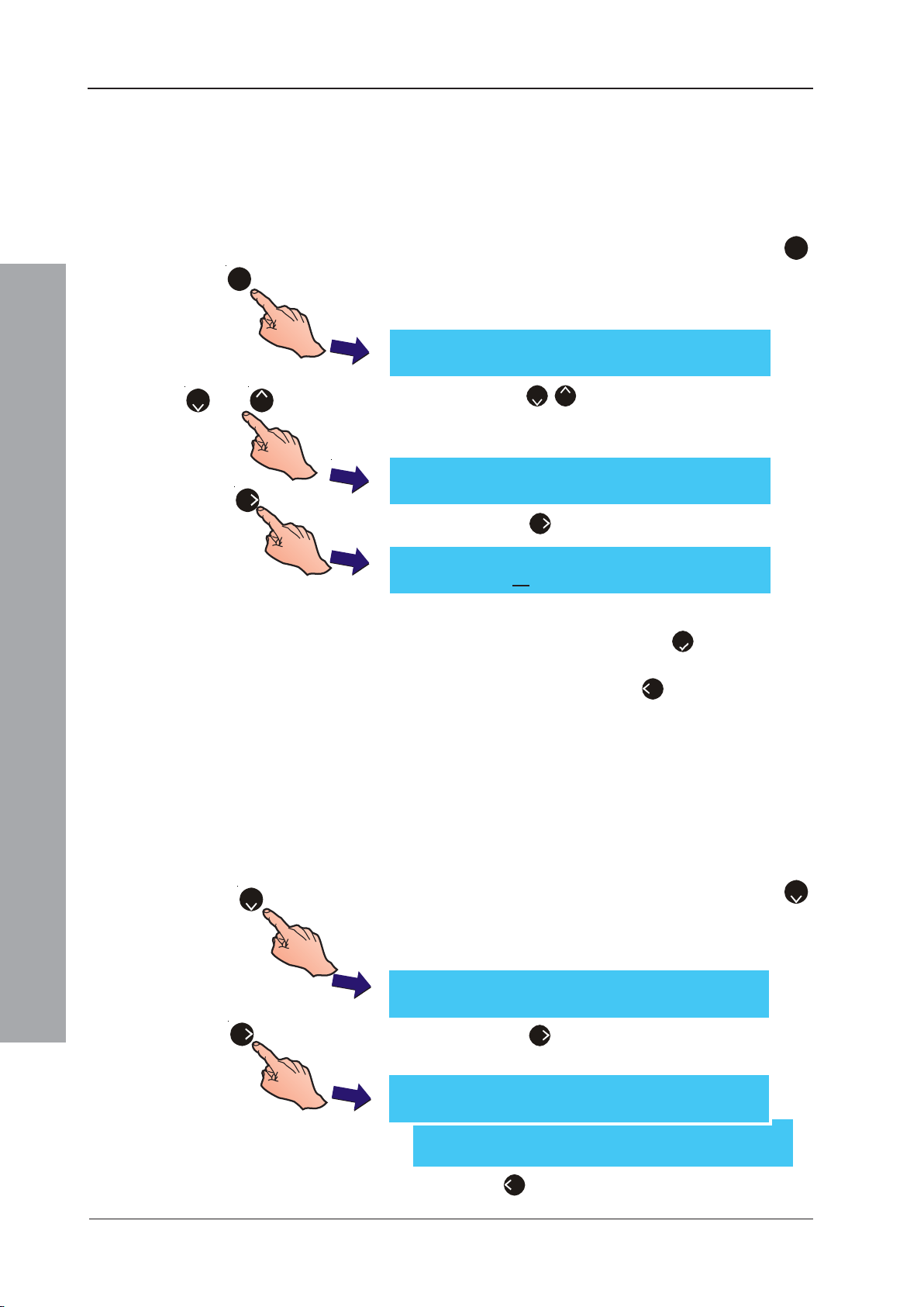
ID50 Series Panel - Installation, Commissioning & Configuration Manual
5.5.4.5 Suspend Comms Limit
This function is only selectable if Third Party was selected
at the RS485 Protocol screen. A time for suspending the
RS485 Third Party Datalink of up to 300 minutes can be
set. Alternatively, a value of ‘0’ can be entered when an
indefinite period is required.
1 From the Peripheral Options screen, press the ‘1’
1
[Setup] RS485 Protocol = THIRD PARTY
> : Change ¦ : More < : Exit
button on the numeric keypad to select the RS485
Communications port option. The RS485 Protocol
setup screen is displayed:
or
82
[Setup] Suspend Comms Limit = 0 mins
6
> : Change ¦ : More < : Exit
[Setup] Suspend Comms Limit = 0 mins
Enter new value 60 : Confirm < : Cancel
5.5.4.6 RS232 Protocol
Configuration Mode
2 Press the ‘2/8’ buttons to scroll through the Setup
menu until the Suspend Comms Limit screen is
displayed.
3 Press the ‘6’ button if the limit is to be changed.
4 Using the numeric keypad, enter the new value (in
minutes) and confirm using the ‘5’ button. The LCD
automatically returns to the Suspend Comms Limit
screen. Alternatively, press ‘4’ to cancel the change.
This option enables the protocol of the RS232 port to be
configured for use with either driver:
a. External printer (default selection).
b. Third party equipment
2
6
997-263-000-11, Issue 11
January 2010
c. GSM Modem.
1 From the Peripheral Options screen, press the ‘2’
button on the numeric keypad to select the RS232
Communications port option. The RS232 Protocol
setup screen is displayed:
[Setup] RS232 Protocol = PRINTER
> : Change ¦ : More < : Exit
2 Press the ‘6’ button to toggle between ‘PRINTER’,
‘THIRD PARTY’ or ‘GSM MODEM’.
[Setup] RS232 Protocol = THIRD PARTY
> : Change ¦ : More < : Exit
[Setup] RS232 Protocol = GSM MODEM
> : Change ¦ : More < : Exit
3 Press ‘4’ to return to the Peripheral Options menu
screen.
56
Page 61
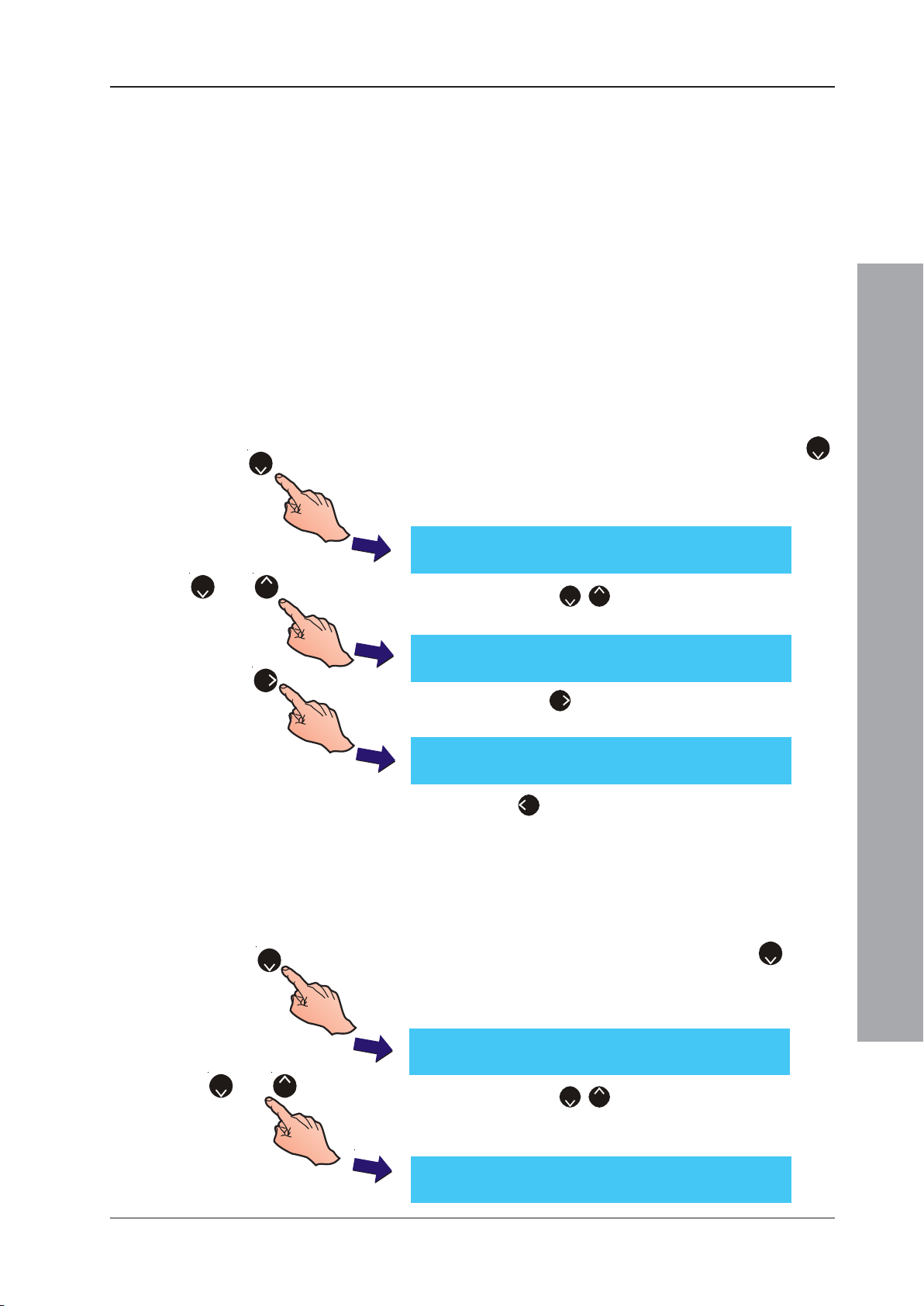
ID50 Series Panel - Installation, Commissioning & Configuration Manual
5.5.4.7 Print Control or Third Party
This option is dependent upon the selected RS232
operating mode (see Section 5.5.4.6).
If the RS232 port is set to PRINTER, the available ‘Print
Control’ options are:
a. BASIC - slow mode, no handshaking (default option).
b. XON/XOFF - software control of data flow.
If the RS232 port is set to THIRD PARTY, the available
‘Third Party’ options are:
c. Full duplex (default option).
d. Half duplex.
If the RS232 port is set to GSM MODEM, refer to Section
5.5.4.9 for details.
or
2
82
6
1 From the Peripheral Options screen, press the ‘2’
button on the numeric keypad to select the RS232
Communications port option. The RS232 Protocol
setup screen is displayed first:
[Setup] RS232 Protocol = PRINTER
> : Change ¦ : More < : Exit
2 Press the ‘2/8’ buttons to scroll through the
options until the Print Control screen is displayed.
[Setup] Print Control = BASIC
> : Change ¦ : More < : Exit
3 Press the ‘6’ button to toggle between ‘BASIC’ and
‘XON/XOFF’
[Setup] Print Control = XON/XOFF
> : Change ¦ : More < : Exit
4 Press ‘4’ to return to the Peripheral Options menu screen.
Configuration Mode
5.5.4.8 Third Party Datalink Monitoring
This function is only selectable if Third Party was selected
at the RS232 Protocol screen. Monitoring of the third party
datalink can be enabled or disabled as follows:
2
or
2
8
1 From the Setup menu screen, press the ‘2’ button
on the numeric keypad to select the RS232
Communications port option. The RS232 Protocol
setup screen is displayed:
[Setup] RS232 Protocol = THIRD PARTY
> : Change ¦ : More < : Exit
2 Press the ‘2/8’ buttons to scroll through the
Peripheral Options until the Data Link Monitoring
screen is displayed.
[Setup] Data Link Monitoring = ENABLED
> : Change ¦ : More < : Exit
57
997-263-000-11, Issue 11
January 2010
Page 62
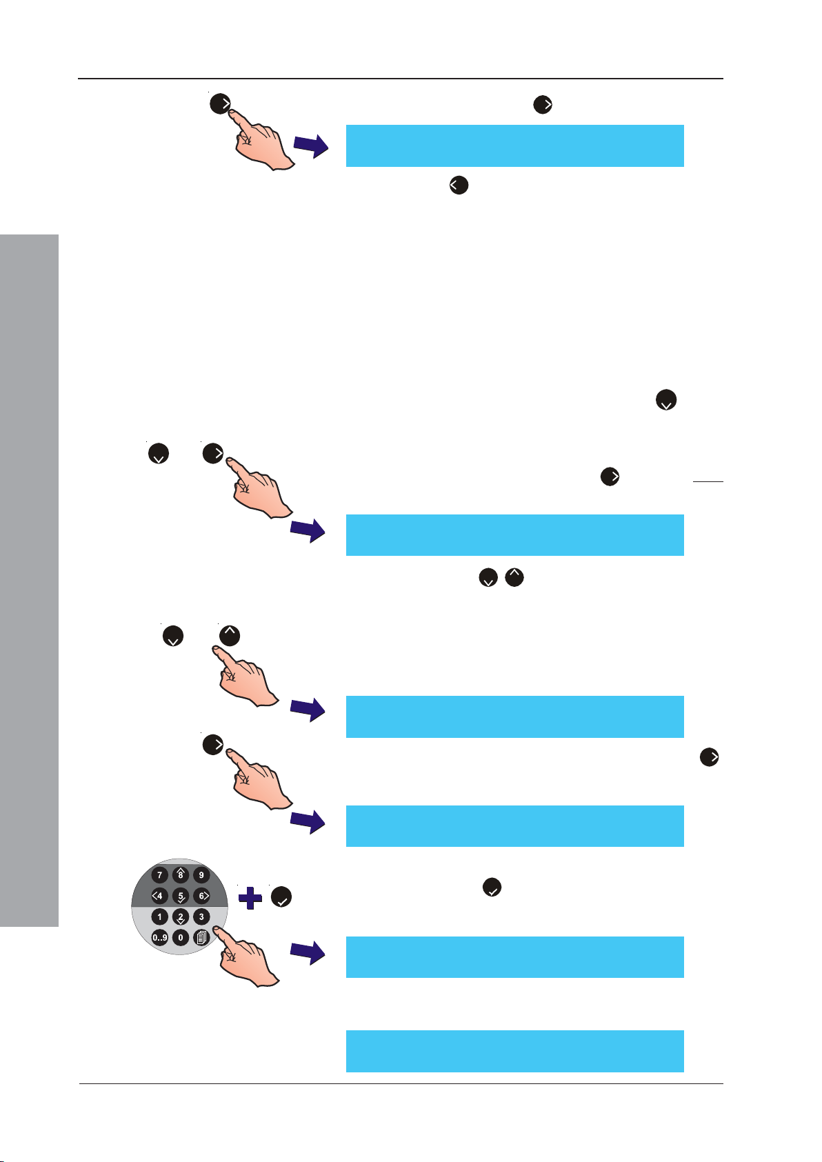
ID50 Series Panel - Installation, Commissioning & Configuration Manual
6
3 If required, press the ‘
6
’ button to select DISABLED.
[Setup] Data Link Monitoring = DISABLED
> : Change ¦ : More < : Exit
4 Press ‘
4
’ to exit the Data Link Monitoring screen
and return to the Peripheral Options menu screen.
5.5.4.9 GSM Communications Module Event Messaging
The ID50/60 Series panels are now able to be configured
for use with a GSM Communications Module (GCM) (panel
software version 5.07, or later). This function is selected
through the RS232 Protocol option screen. The available
options are: changing the GSM PIN number; entry of up
to five GSM network telephone numbers and selecting
panel event categories for text message notification.
1 From the Setup menu screen, press the ‘2’ button
on the numeric keypad to select the RS232
Communications port option. The RS232 Protocol
2
and
6
setup screen is displayed. The PRINTER (default)
option is displayed first. Press the ‘6’ pushbutton twice
to select the GSM MODEM RS232 protocol option:
[Setup] RS232 Protocol = GSM MODEM
> : Change ¦ : More < : Exit
or
2
8
[Setup] Change GSM PIN Number:
Configuration Mode
6
> : Change ¦ : More < : Exit
[Setup] Enter current PIN : _
5
2 Press the ‘2/8’ pushbuttons to display more
configuration options for the GSM. The editable
options are: GSM PIN Number (to enable a change
of PIN number) and discrete GSM edit screens which
allow up to 5 GSM network numbers to be configured
to receive event messages from the ID50/60 Series
fire alarm control panels.
3 To change the GSM PIN number, press the ‘6’
pushbutton and the screen asks for the current PIN
to be entered (this is provided with the SIM card):
<: Exit
4 Using the numeric keypad enter the new PIN number
and press ‘5’ when finished. You will now be
prompted to enter the new PIN number again as
confirmation:
997-263-000-11, Issue 11
January 2010
[Setup] Confirm new PIN : _
<: Exit
If the GSM PIN number change was successful you
will get the following message:
[Setup] PIN Change complete
<: Exit
58
Page 63
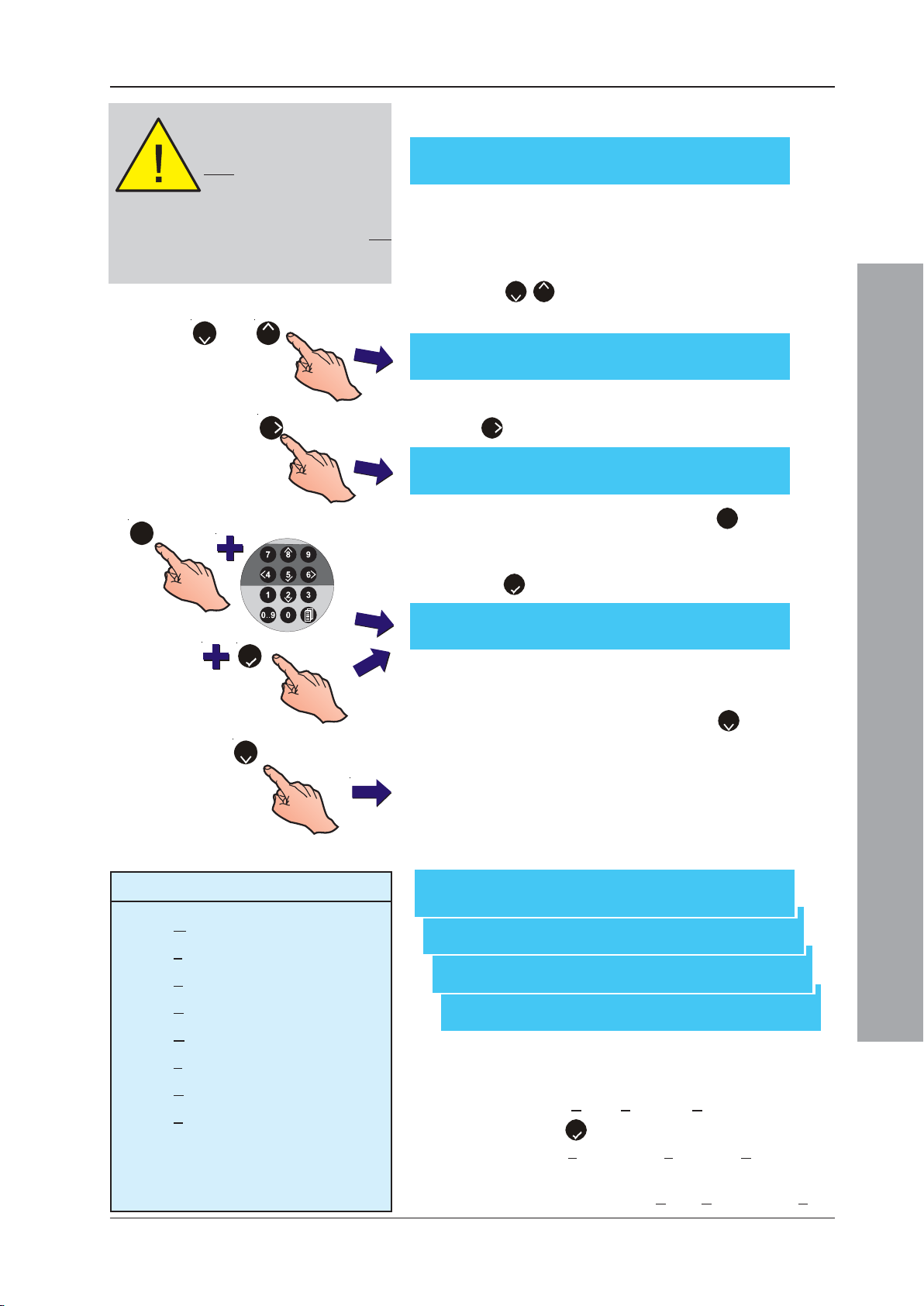
ID50 Series Panel - Installation, Commissioning & Configuration Manual
Use care when entering the PIN
number to avoid a failed PIN
change. You are only allowed
three attempts at entering a PIN
code before it is locked out.
Likewise, if you have entered an incorrect PIN
and restart the panel you are only allowed
one
more attempt before the PIN is locked out.
Don’t restart the panel if the PIN is incorrect.
or
82
6
1
However, if the change was not successful the
following message is displayed:
[Setup] PIN Change failed
<: Exit
The PIN change failure may be due to an incorrect
PIN number having been entered.
5 To enter the GSM network telephone numbers, press
the ‘2/8’ pushbutton repeatedly until the GSM Item
1 screen is displayed:
[Setup] GSM Item 1:
>: Change ¦: More <: Exit
6 To enter the GSM network contact number, press the
‘6’ pushbutton to display the following options:
[Setup] GSM Item 1:
1: Number 2: Notifications [A1F1P1.....]
7 Using the numeric keypad press ‘1’ to select the
number entry option. Again, using the numeric keypad
enter the required number, without spaces and press
the 5’ pushbutton when finshed.
5
2
Notifications: Code Letters
A* - Alarm condition (A1, A5, or AA)
F* - Fault condition (F1, F5, or FA)
P* - Pre-alarm condition (P1, P5, or PA)
C-Controls (user action at panel)
G- General Disablement
Z-Zone Disablement
D-Device Disablement
S-System Disablement, e.g. sounder
output disabled, transmission output
disabled.
[GSM number entry field ] ¦ : Char : Done
> : Next < : Previous u1:Delete u3:Insert
Note: The number entry is limited to 20 digits although
the first character may be a ‘+’.
8 Using the numeric keypad press the ‘2’ pushbutton to
select the ‘Notifications’ option. Selection of Alarm, prealarm, fault and various disable classes can be
made.The following event notification options are
selectable (see table below left for a description of
the Notifications code letters used and, for A, F and P
events, the first one, first five or all events that can be
configured to be sent.
[Setup] Options [A1F1P1.....] : 1 : Alarm
2 : Fault 3 : Pre-Alarm 4 : Controls ¦: More
[Setup] Options [A1F1P1.....] :
5 : General Disable 6 : Zone Disable ¦: More
[Setup] Options [A1F1P1.....] :
7 : Device Disable ¦: More
[Setup] Options [A1F1P1.....] :
8 : System Disable ¦: More
9 Use the numeric keypad to select/deselect any of the
event notification options. The characters displayed in
the square brackets indicate which options have been
selected. For Alarm, Fault and Pre-alarm repeatedly
pressing the 5’ pushbutton toggles the selection of:
not selected, 1st event, first 5 events or All events.
Configuration Mode
* Can be configured to send the first event
(default), first five events or all events.
Note: For each GSM number entered the following options
are assigned by default: Alarm, Pre-alarm and Fault.
59
997-263-000-11, Issue 11
January 2010
Page 64
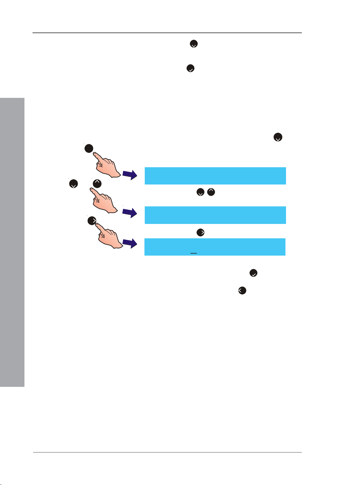
ID50 Series Panel - Installation, Commissioning & Configuration Manual
10 Use the ‘2’ pushbutton, select the remaining four GSM
Number entry fields, as required, and repeat steps 4 to 9
above. Once all the required numbers have been entered,
press ‘
5
’ to exit. All numbers are saved on exiting.
5.5.4.10 Suspend Comms Limit
This function is only selectable if Third Party was selected
at the RS232 Protocol screen. Used to limit the maximum
time for suspending the RS232 Third Party Datalink. Up
to 300 minutes can be set. Alternatively, a value of ‘0’
can be entered when an indefinite period is required.
1 From the Setup menu screen, press the ‘2’ button
on the numeric keypad to select the RS232
Communications port option. The RS232 Protocol
setup screen is displayed:
2 Press the ‘2/8’ buttons to scroll through until the
Suspend Comms Limit screen is displayed.
or
1
[Setup] RS232 Protocol = THIRD PARTY
82
> : Change ¦ : More < : Exit
[Setup] Suspend Comms Limit = 0 mins
6
> : Change ¦ : More < : Exit
[Setup] Suspend Comms Limit = 0 mins
Enter new value 60 : Confirm < : Cancel
Configuration Mode
3 Press the ‘6’ button if the limit is to be changed.
4 Using the numeric keypad, enter the new value (in
minutes) and confirm using the ‘5’ button. The LCD
automatically returns to the Suspend Comms Limit
screen. Alternatively, press ‘4’ to cancel the change.
997-263-000-11, Issue 11
January 2010
60
Page 65
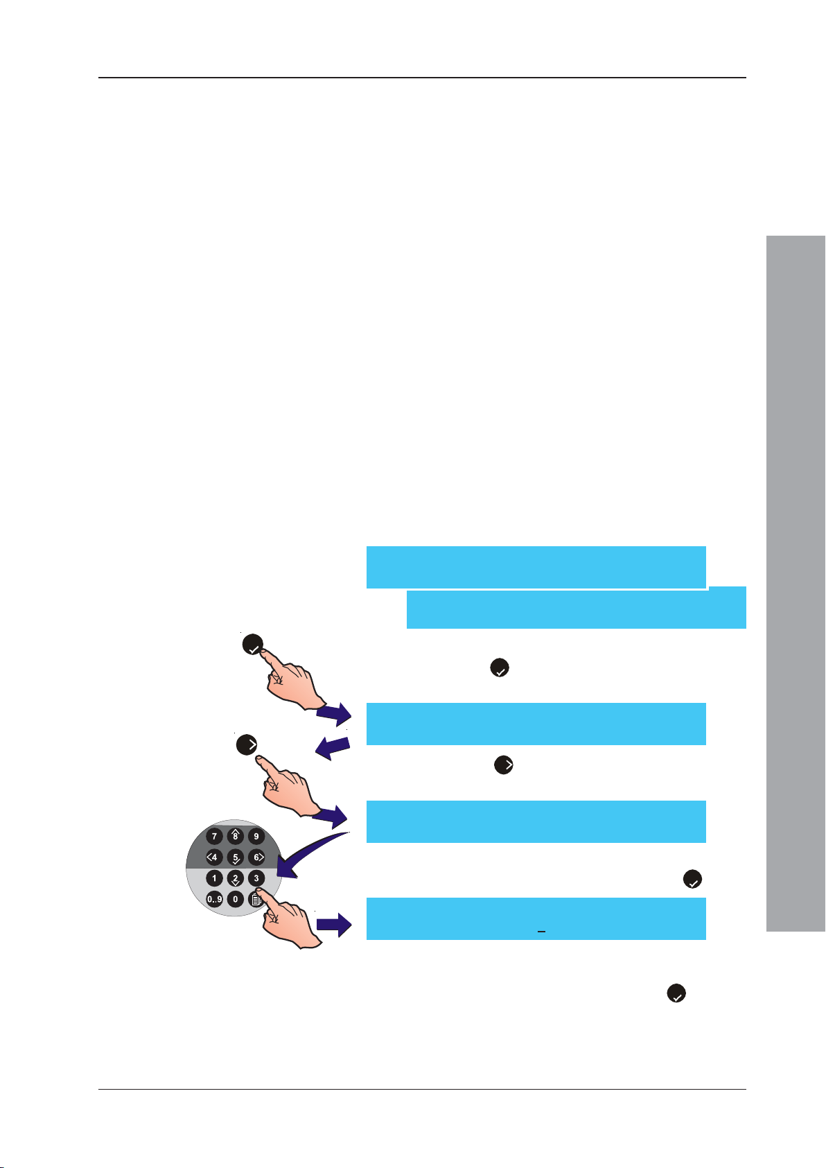
ID50 Series Panel - Installation, Commissioning & Configuration Manual
5.5.5 Day/Night Settings
The Day/Night Settings menu allows configuration of the
following functions:
a. Day Mode
b. Weekend Night Mode
c. Day Mode Start
d. Primary Delay Time
e. Extend Delay Time
f. Heat Detector End Delay
g. Day Mode 2 Zone End Delay
h. Delay Indication.
5.5.5.1 Day Mode Activity
The Day mode function enables the panel to switch
between two (2) preset sensitivity levels. Day mode is set
for one time period per day for seven days unless the
Weekend night mode is also configured (Section 5.5.5.2,
Weekend Night Mode). The manual activation/deactivation
of delayed outputs when the Day mode is active or inactive
can also be configured.
Optiplex mult-sensors: the smoke detection component
is turned off during the Day Mode period.
To configure the Day mode period:
[S1 Setup] 1: Panel Options
2: Site Details 3: Device Options ¦ : More
[S1 Setup] 4: Peripheral Options
5: Day / Night Settings ¦ : More
5
6
1 From the Setup menu screen, using the numeric keypad
press the ‘5’ button to enter the Day/Night Settings
menu. The Day Mode Activity screen is displayed first.
[Setup] Day mode activity = DISABLED
> : Change 1 : Disable ¦ : More < : Exit
2 Press the ‘6’ button to enter the day mode active
period start time.
[Setup] Day mode activity = DISABLED
Enter start time : _ < : Cancel
3 Using the numeric keypad, enter the appropriate time in
the 24-hour clock format and confirm using the ‘5’ button.
Configuration Mode
[Setup] Day mode activity = DISABLED
Enter start time : 08:00 < : Cancel
4 The LCD displays a prompt to enter an end Day mode time.
Use the numeric keypad to enter the appropriate time in the
24-hour clock format and confirm using the ‘5’ button.
61
997-263-000-11, Issue 11
January 2010
Page 66
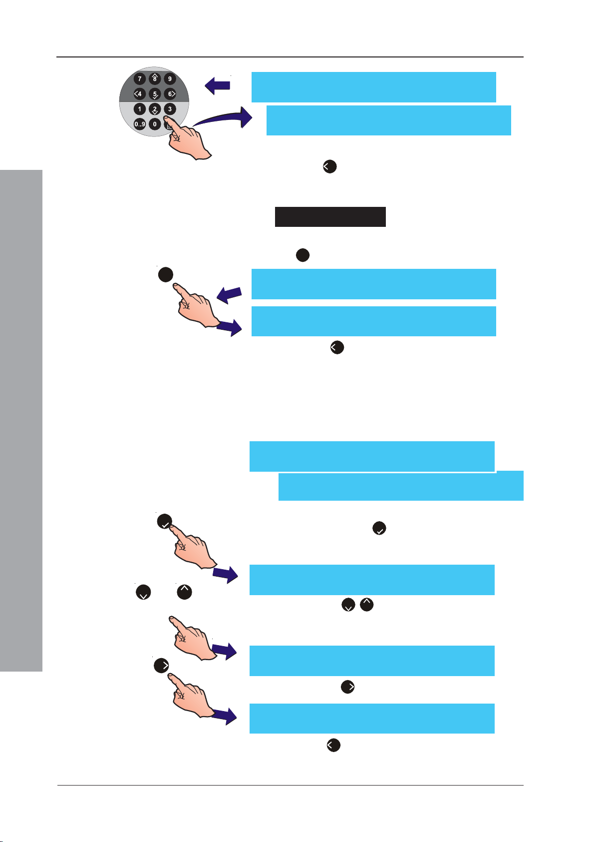
ID50 Series Panel - Installation, Commissioning & Configuration Manual
[Setup] Day mode activity = DISABLED
Enter finish time : _0:00 < : Cancel
[Setup] Day mode activity = 08:00 -> 18:00
> : Change 1 : Disable ¦ : More < : Exit
5 Press ‘4’ to save all changes and return to the Setup
menu screen.
To disable Day mode
1 With the Day mode activity menu displayed, press the
‘1’ button on the numeric keypad.
1
5.5.5.2 Weekend Night Mode
[S1 Setup] 1: Panel Options
5
Configuration Mode
[Setup] Day mode activity = 08:00-> 18:00
> : Change 1 : Disable ¦ : More < : Exit
[Setup] Day mode activity = DISABLED
> : Change 1 : Disable ¦ : More < : Exit
2 Press ‘4’ to exit and return to the Setup menu
screen.
If Weekend night mode is enabled, the panel disregards
the Day mode period on the two days of the week that
coincide with the weekend. To set this mode active:
2: Site Details 3: Device Options ¦ : More
[S1 Setup] 4: Peripheral Options
5: Day / Night Settings ¦ : More
1 From the Setup menu screen, using the numeric
keypad press the ‘5’ button to display the Day/Night
Settings screen.The Day Mode Activity screen is
displayed first.
or
2
6
997-263-000-11, Issue 11
January 2010
[Setup] Day mode activity = DISABLED
8
> : Change 1 : Disable ¦ : More < : Exit
2 Press the ‘2/8’ buttons to step through the Day/
Night Settings options until the Weekend night mode
screen is displayed.
[Setup] Weekend night mode = Disable
> : Change ¦ : More < : Exit
3 Press the ‘6’ button to toggle this function.
[Setup] Weekend night mode = Enable
> : Change ¦ : More < : Exit
4 Press ‘4’ to exit and return to the Setup menu
screen.
62
Page 67
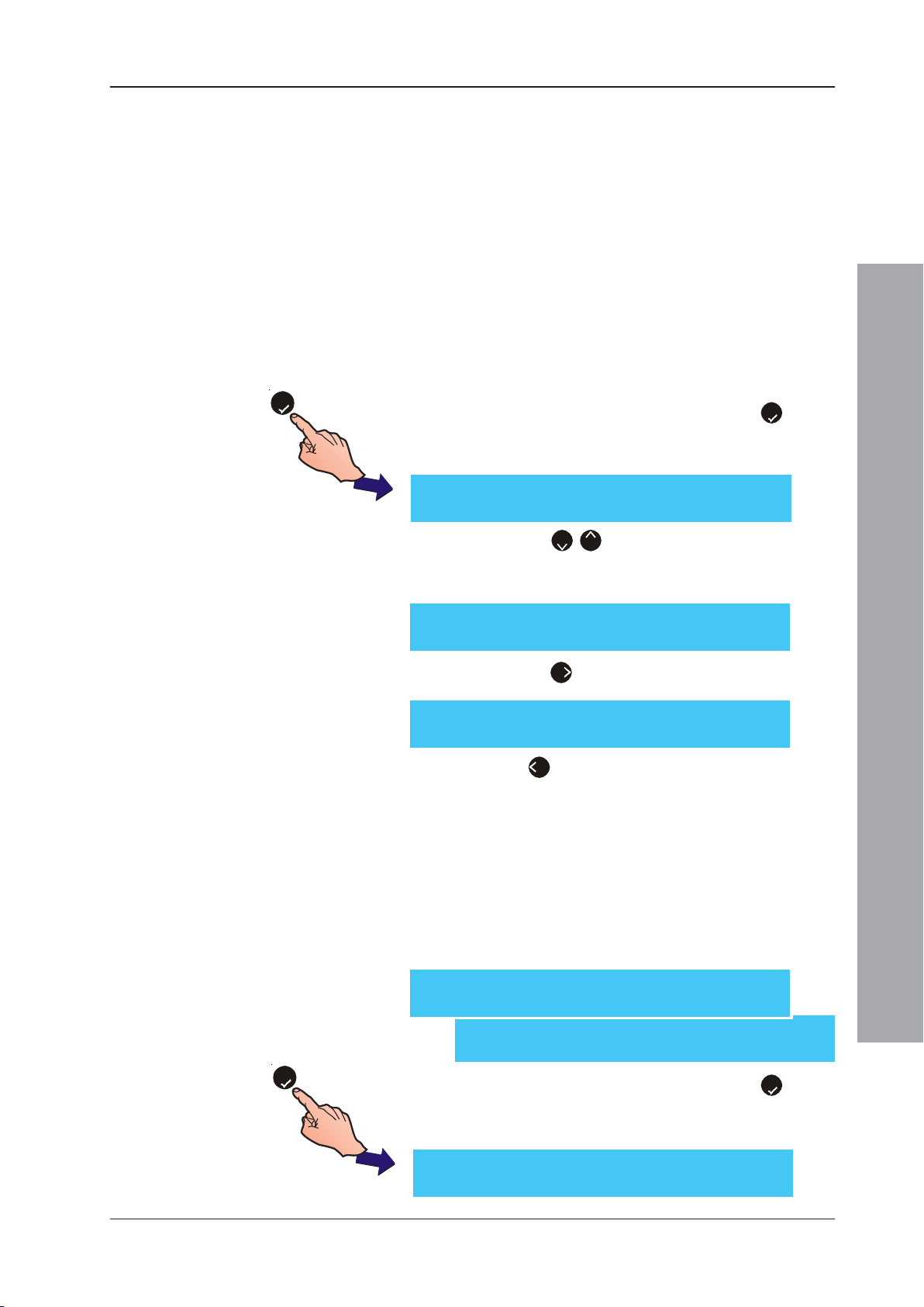
ID50 Series Panel - Installation, Commissioning & Configuration Manual
5.5.5.3 Day Mode Start
This option enables the start of the day mode period to
be set manually (default) or automatically.
Digital Input 1 can be configured for manual activation of
day mode (see Section 5.5.3.4). When the day mode
period is activated via Digital Input 1, a continuous (rather
than momentary) condition is required. However, if a day
mode period has been configured (refer to Section 5.5.5.1
Day Mode Activity) and is currently active, an input via
Digital Input 1 will de-activate day mode until it is released
or the day mode activation expires at the end of the set
period. Delays to outputs, manually-activated using Digital
Input 1, will be cancelled automatically at the end of the
set day mode period. To set Day Mode Start:
5
1 From the Setup menu screen, press the ‘5’ button
on the numeric keypad to enter the Day/Night Settings
menu. The Day Mode Activity screen is displayed first.
[Setup] Day mode activity = DISABLED
> : Change 1 : Disable ¦ : More < : Exit
2 Press the ‘2/8’ buttons to step through the Day/
Night Settings options until the Day Mode Start screen
is displayed.
[Setup] Day Mode start = Manual
> : Change ¦ : More < : Exit
3 Press the ‘6 button to select Automatic:
[Setup] Day Mode start = Automatic
> : Change ¦ : More < : Exit
4 Press ‘4’ to exit and return to the Setup menu
screen.
5.5.5.4 Primary/Extend Delay Timers
Configuration Mode
As part of Day Mode configuration (see Section 5.5.5.1) the
Primary Delay Timer allows an initial investigation time of
up to 300 seconds (default 30 seconds) to be entered or
changed. The Extend Delay Timer allows an additional delay
(default - 3 minutes) to be entered or changed. The total
delay time cannot exceed 10 minutes. To set delay times:
[S1 Setup] 1: Panel Options
2: Site Details 3: Device Options ¦ : More
[S1 Setup] 4: Peripheral Options
5: Day / Night Settings ¦ : More
5
1 From the Setup menu screen, press the ‘5’ button
on the numeric keypad to enter the Day/Night Settings
menu. The Day Mode Activity screen is displayed first.
[Setup] Day mode activity = DISABLED
> : Change 1 : Disable ¦ : More < : Exit
63
997-263-000-11, Issue 11
January 2010
Page 68
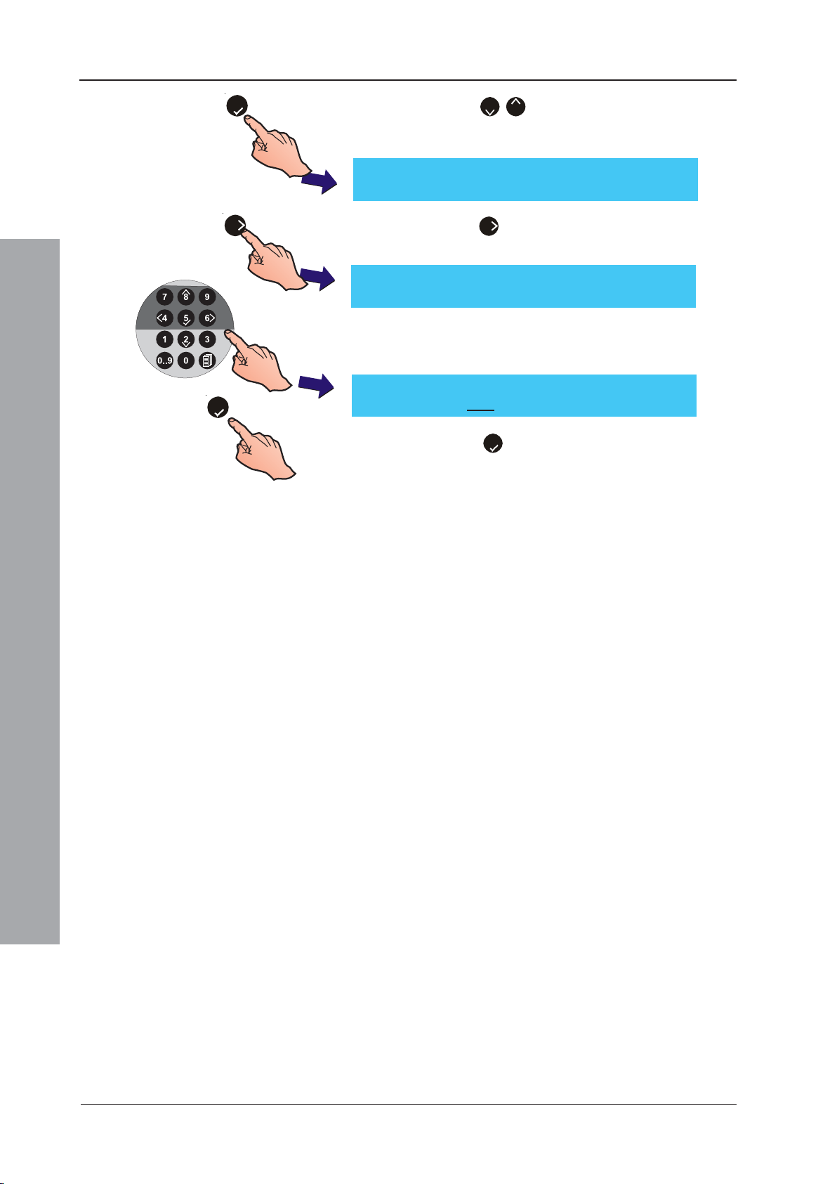
ID50 Series Panel - Installation, Commissioning & Configuration Manual
5
6
5
2 Press the ‘
Night Settings options until the Primary Delay Time
screen is displayed.
[Setup] Day mode activity = DISABLED
> : Change 1 : Disable ¦ : More < : Exit
3 Press the ‘
for the new value:
[Setup] Primary Delay Time = 30 Seconds
Enter new value ____ : Confirm < : Cancel
4 Enter the required delay time using the numeric
buttons; (e.g. to set the delay time to the maximum
value of 300 seconds, first enter ‘3’, then enter ‘0’, ‘0’).
[Setup] Primary Delay Time = 30 Seconds
Enter new value 300 : Confirm < : Cancel
5 Press the ‘5’ button to confirm and return to the
Setup menu screen.
6 Repeat steps 1 to 5 for the Extend Delay Time, using
the Extend Delay Time display and a maximum value
of 10 minutes.
2/8
’ buttons to step through the Day/
6
’ button. The display then prompts you
Configuration Mode
997-263-000-11, Issue 11
January 2010
64
Page 69
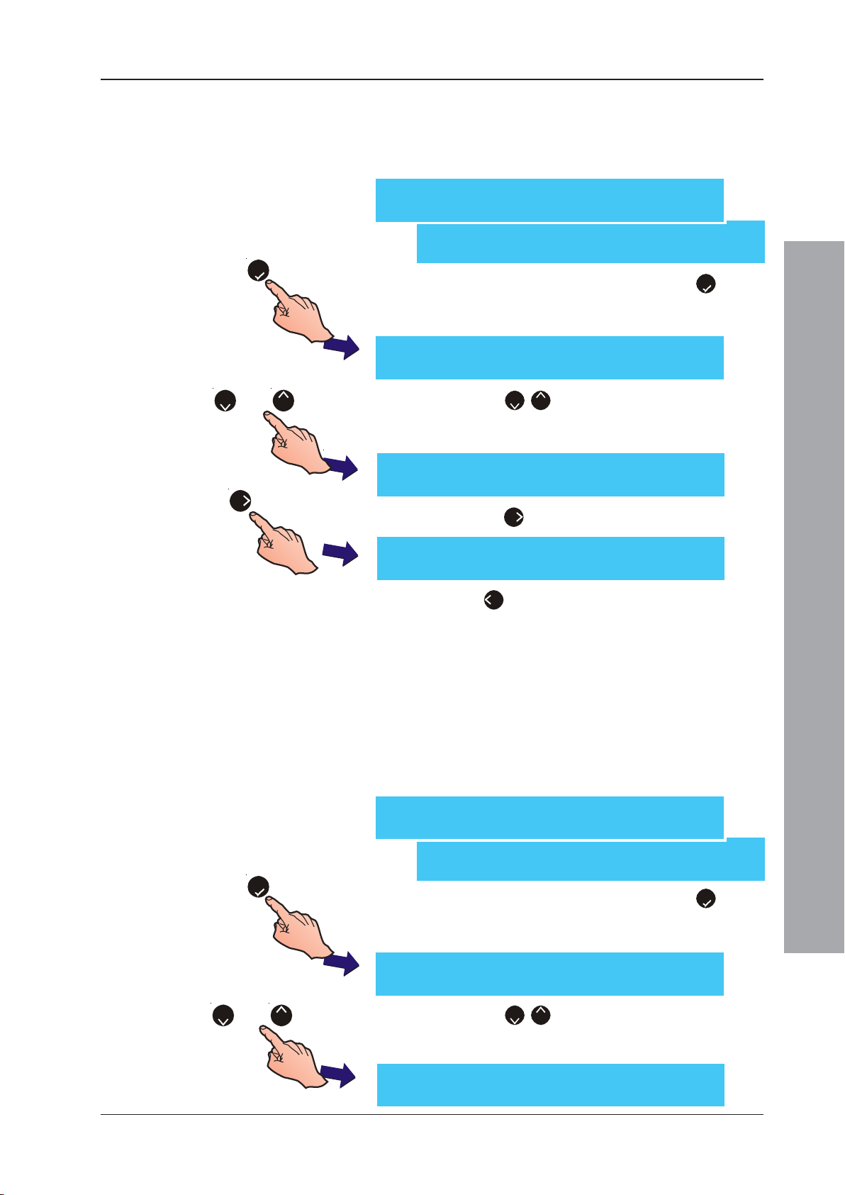
ID50 Series Panel - Installation, Commissioning & Configuration Manual
5.5.5.5 Heat Det. End Delay
The Day Mode function, Delays to outputs, can be
cancelled when a heat sensor goes into alarm. To select
the Heat Det. End Delay option:
[S1 Setup] 1: Panel Options
2: Site Details 3: Device Options ¦ : More
[S1 Setup] 4: Peripheral Options
5: Day / Night Settings ¦ : More
5
1 From the Setup menu screen, press the ‘5’ button
on the numeric keypad to enter the Day/Night Settings
menu. The Day mode activity screen is displayed first.
[Setup] Day mode activity = DISABLED
> : Change 1 : Disable ¦ : More < : Exit
or
2
8
6
2 Press the ‘2/8’ buttons to step through the Day/
Night Settings options until the Heat Det. End Delay
screen is displayed.
[Setup] Heat Det. End Delay = No
> : Change ¦ : More < : Exit
3 Press the ‘6’ button to toggle this function.
[Setup] Heat Det. End Delay = Yes
> : Change ¦ : More < : Exit
4 Press ‘4’ to exit and return to the Setup menu
screen. The selection is saved on exiting.
5.5.5.6 Day Mode 2 Zone Ends Delay
The Day Mode function, Delays to outputs, can be
cancelled, through this Day/Night Settings option, by a
second zone going into alarm. This is an alternative to a
second device in the same zone going into alarm or the
activation of an MCP cancelling active delay timers.
To select the Day Mode 2 Zone Ends Delay option:
[S1 Setup] 1: Panel Options
2: Site Details 3: Device Options ¦ : More
Configuration Mode
or
[S1 Setup] 4: Peripheral Options
5: Day / Night Settings ¦ : More
5
82
1 From the Setup menu screen, press the ‘5’ button
on the numeric keypad to enter the Day/Night Settings
menu. The Day mode activity screen is displayed first.
[Setup] Day mode activity = DISABLED
> : Change 1 : Disable ¦ : More < : Exit
2 Press the ‘2/8’ buttons to step through the Day/
Night Settings options until the Day Mode 2 Zone Ends
Delay screen is displayed.
[Setup] Day Mode 2 Zone Ends Delay = No > : Change ¦ : More < : Exit
65
997-263-000-11, Issue 11
January 2010
Page 70
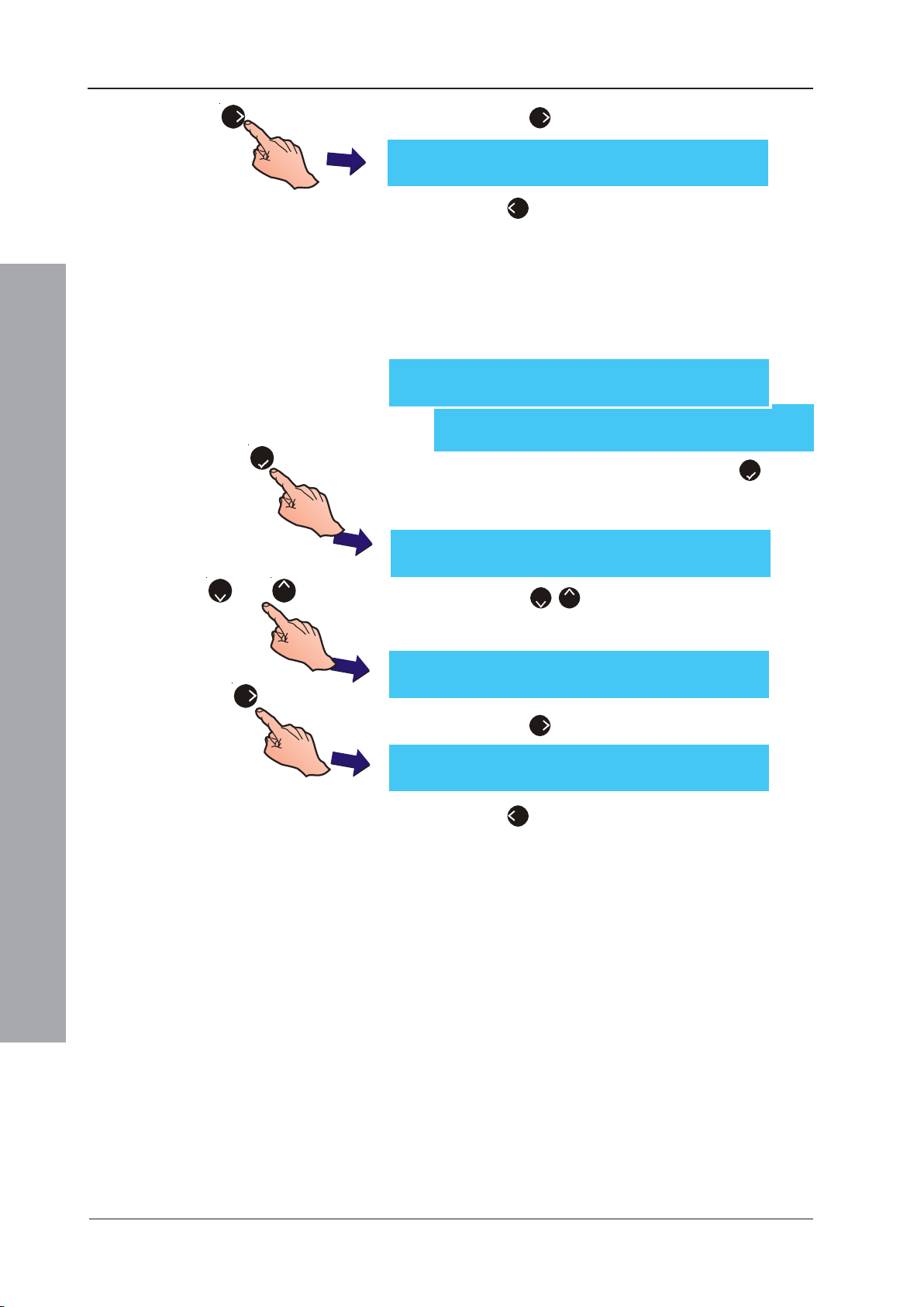
ID50 Series Panel - Installation, Commissioning & Configuration Manual
6
3. Press the ‘6’ button to toggle this function.
[Setup] Day Mode 2 Zone Ends Delay = Yes
> : Change ¦ : More < : Exit
4 Press ‘
screen. The selection is saved on exiting.
4
’ to exit and return to the Setup menu
5.5.5.7 Delays Indication
Select whether the DELAYS ACTIVE and
DISABLEMENTS LEDs are lit or the DELAYS ACTIVE
LED only is lit for active delays using this option.
[S1 Setup] 1: Panel Options
2: Site Details 3: Device Options ¦ : More
[S1 Setup] 4: Peripheral Options
5: Day / Night Settings ¦ : More
5
1 From the Setup menu screen, press the ‘5’ button
on the numeric keypad to enter the Day/Night Settings
menu. The Day mode activity screen is displayed first.
[Setup] Day mode activity = DISABLED
> : Change 1 : Disable ¦ : More < : Exit
or
82
[Setup] Delays Ind. = Active/Disable
6
> : Change ¦ : More < : Exit
[Setup] Delays Ind. = Active Only
> : Change ¦ : More < : Exit
Configuration Mode
2 Press the ‘2/8’ buttons to step through the Day/
Night Settings options until the Delays Ind. screen is
displayed.
3 Press the ‘6’ button to toggle this function.
4 Press ‘4’ to exit and return to the Setup menu
screen. The selection is saved on exiting.
997-263-000-11, Issue 11
January 2010
66
Page 71
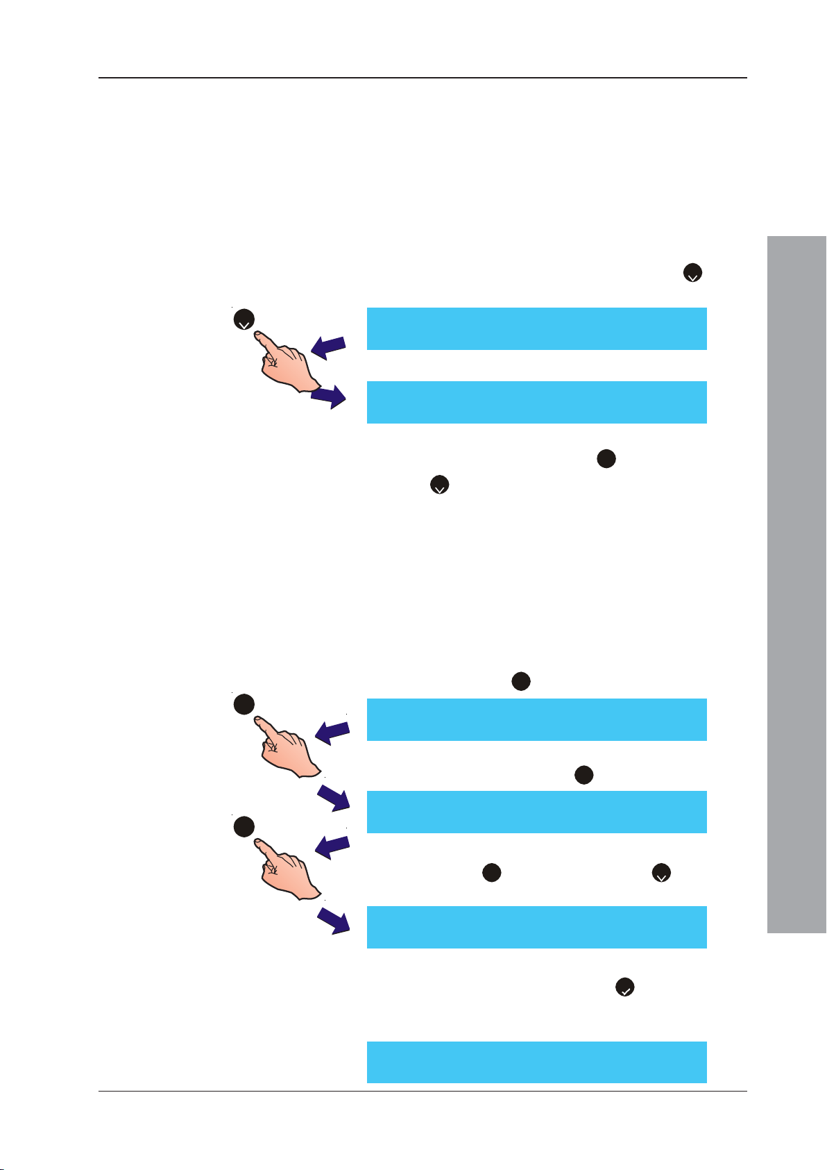
ID50 Series Panel - Installation, Commissioning & Configuration Manual
5.6 Circuit Options
The Circuit options menu offers the facility to individually
auto-configure, manually learn or view the following circuits:
a. Signalling Line Circuit - SLC (loop)
b. On-Board Output Circuits - including sounder, control
and relay circuits.
To select the Circuit options menu:
1 From the Commissioning menu, press the ‘2’ button
on the numeric keypad to access the Circuit option menu.
2
[S1 COMM] 1 : Setup 2 : Circuit
3 : CBE Rules 4 : Zones 5 : Access ¦ : More
2 The LCD displays the Circuit options available.
[S1 Circuit] 1 : SLC Loop 2 : On-Board
3 Select the number corresponding to the type of circuit
that requires changing, i.e. ‘1’ for the SLC Loop, or
‘2’ for On-Board.
The LCD then displays the appropriate Circuit menu
display.
5.6.1 Signalling Line Circuit (SLC) - Devices
This option enables the manual configuration of devices
to a pre-configured analogue addressable SLC loop.
To manually learn devices on the SLC loop:
1 From the Circuit menu screen, below, using the numeric
keypad press ‘1’ to select the SLC loop configuration.
1
[S1 Circuit] 1 : SLC Loop 2 : On-Board
Configuration Mode
2 The LCD displays the Devices and the Learn options. Using
the numeric keypad, press ‘1’ to select the Devices menu.
[S1 SLC] 1 : Devices 2 : Learn
1
3 Select a device option by using the numeric keypad and
pressing ‘1’ to configure sensors or ‘2’ to configure
modules (see Input Modules and Output Modules overleaf).
[S1 Device] 1 : Sensors 2 : Modules
4 At the prompt, using the numeric keypad enter an address
number and confirm using the ‘5’ button. When the
required device address has been entered, the LCD shows
the current settings and the available editing functions.
[Sensor] Enter Address____
67
997-263-000-11, Issue 11
January 2010
Page 72
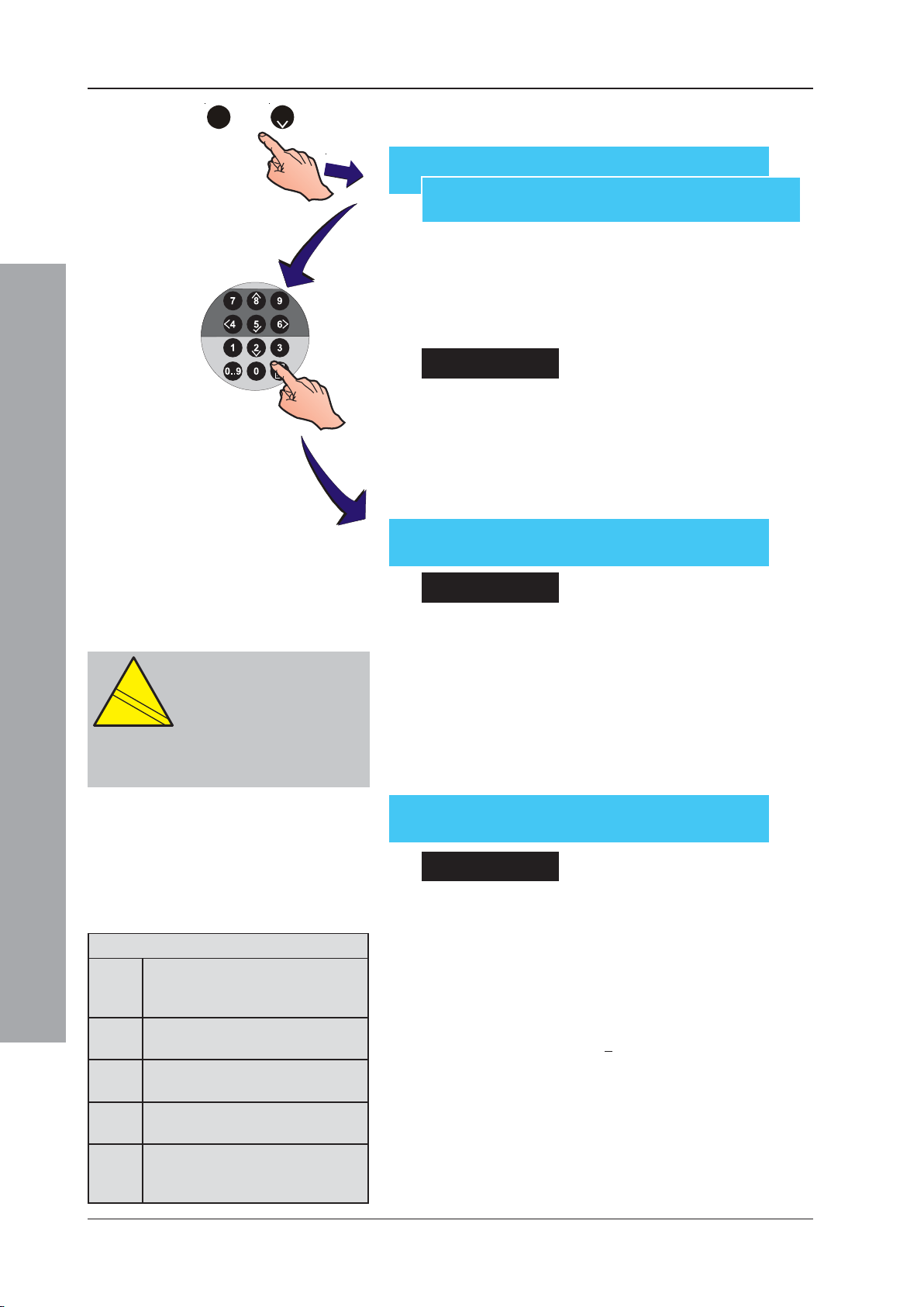
ID50 Series Panel - Installation, Commissioning & Configuration Manual
EN
12094-1
!
or
1
2
If no device is found at the selected address, the LCD
displays one of the messages below:
[Sensor] Snn (xxx) No device learnt
[Module] Mnn (xxx) No device learnt
A specific address can only be configured if:
a. A device has previously been auto-learnt at the
address, or
b. The off-line tool was used to configure the device type
present.
Sensors
The following sensor configuration settings are selectable:
a. The assigned zone (see Section 5.6.1.1, Zone Setting),
b. The sensor sensitivity (see Section 5.6.1.2, Sensor
Sensitivity Setting), and
c. The device text string (see Section 5.8, Zone Texts).
[Sensor nn - AAA] 1 : Zone (nn)
3 : Sensitivity 4 : [ Blank/Existing Text ]
CAUTION:
This product is not compliant
EN
12094-1
!
with EN 12094-1.
Fire extinguishing installations in
Europe are required to be certified as
compliant to this standard.
[Module nn - AAA] 1 : Zone (nn) 2 : Type
Configuration Mode
Extinguishing System Outputs
ESE Extinguishing System Trigger
(not monitored /not disabled by
FWP4)
EST Extinguishing System Trigger
(not monitored)
ESO Extinguishing System Output
(monitored)
RLE Relay Output Module (not
monitored /disabled by FWP4)
CTE Control Output Module
(monitored for open and short
circuits /disabled by FWP4)
3 : CBE Rule (nn) 4 : [ Blank/Existing Text ]
Input Modules
The following input module configuration settings are selectable:
a. The assigned zone (see Section 5.6.1.1, Zone Setting),
b. The type of input device (MCP, DKM, MON, ZMX, MNS,
MRL, IRL; Extinguishing System inputs: AUX - Hold Switch
and Abort Switch (see Section 5.6.1.3, Type Setting),
Note: The AUX device type CANNOT be changed.
c. The device text string (see Section 5.8, Text Editing).
Output Modules
The following output module configuration settings are
selectable:
a. The assigned zone (see Section 5.6.1.1, Zone Setting),
b. The type of output device (SDR, SDH1, CTL, RLY,
EST2, ESO2, ESM, TxD, ESE2, RLE2 and CTE2) (see
Section 5.6.1.3, Type Setting).
1
Sounders enabled with high-load monitoring function.
2
These output device types are subject to extinguishing
system disablement if the option to automatically disable
transmission and extinguishing system devices is
configured (refer to Section 5.5.3.14 TD/ES Disablement
at Access Level 2).
c. The CBE Rule number. It is NOT possible to change
the configuration of the associated CBE Rule.
997-263-000-11, Issue 11
January 2010
68
Page 73
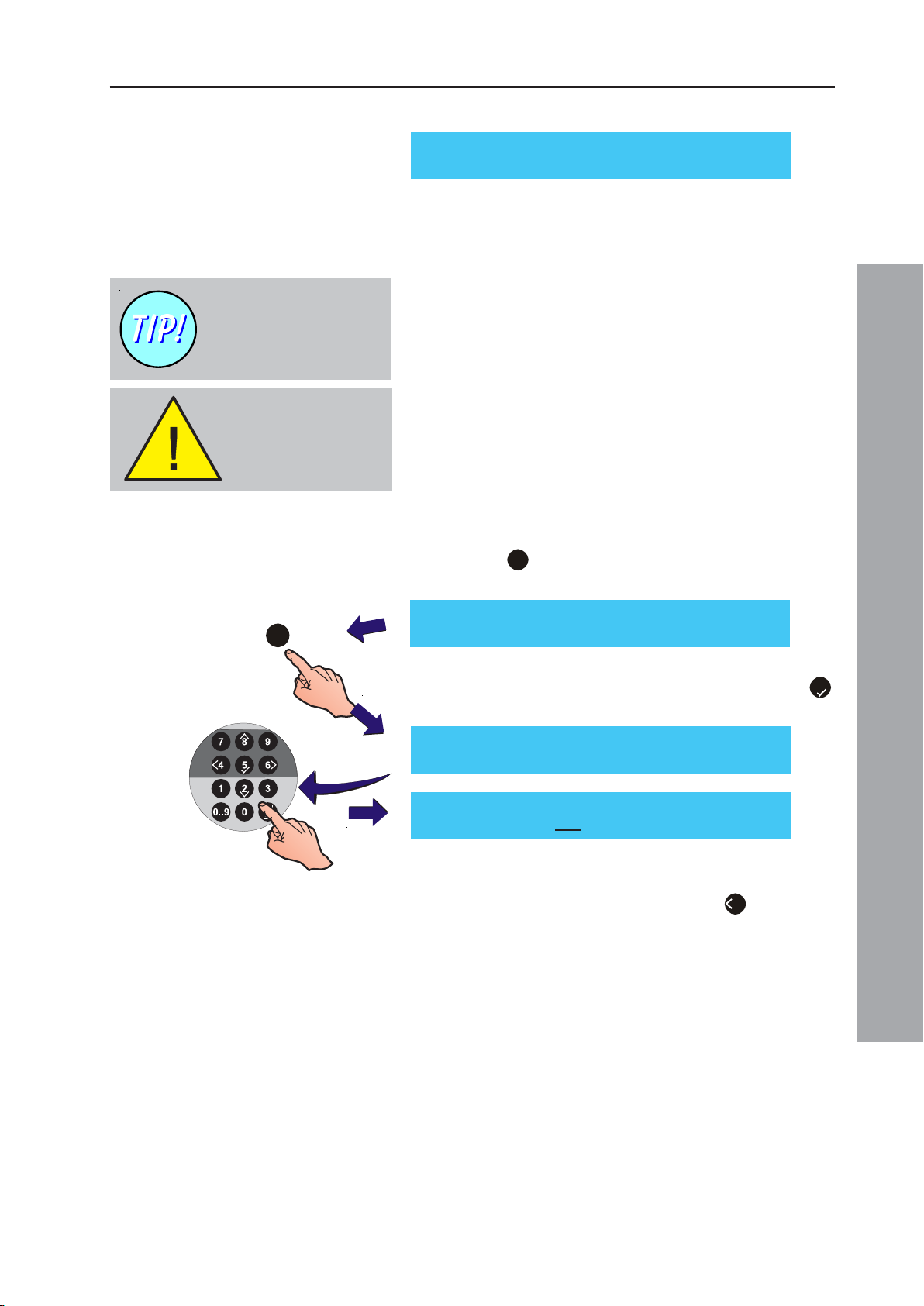
ID50 Series Panel - Installation, Commissioning & Configuration Manual
d. The device text string (see Section 5.8, Text Editing).
[Module nn - AAA] 1 : Zone (nn) 2 : Type
3 : CBE Rule (nn) 4 : [ Blank/Existing Text ]
5.6.1.1 Zone Setting
This option is used during manual configuration to assign
a specific device to a specific zone. The option is
accessed from the Commissioning Menu.
The procedure for
changing the zone of a
module is the same as for
a sensor.
Fire Inputs can only be
assigned to
Zones 1 to 16.
A maximum of 32 possible zones can be configured,
consisting of 16 Fire alarm zones (1 to 16) and 16
secondary zones (17 to 32). The secondary zones are used
for AUX plant alarm and warning inputs. Device types SDR,
SDH, CTL, RLY, EST, ESO, ESM, TxD, ESE, RLE and
CTE can be in any zone.
To change the zone of a specified sensor or module,
selection of either sensors or modules at the Devices
menu is first required. If sensors are selected, the display
prompts for zone editing, as follows;
1 From the menu displaying the device attributes, press
the ‘1’ button on the numeric keypad to access the
Zone Setting menu:
[Sensor nn - AAA] 1 : Zone (nn)
1
3 : Sensitivity 4 : [ Blank/Existing Text ]
2 Using the numeric keypad, enter the required zone
number between 1 and 16 and confirm using the ‘5’
button.
[Sensor nn - AAA] 1 : Zone (nn)
Enter New Zone = ____ < : Cancel
[Sensor nn - AAA] 1 : Zone (nn)
Enter New Zone = 01 < : Cancel
If the entered number is out of the permissible range,
the zone number reverts to that previously allocated.
To-enter the zone number or press ‘4’ to cancel.
Note: Standard input modules can be assigned to any of
the 32 zones. Conventional detector input modules
(ZMX) can be assigned to zones 1 to 16 only. When
an input module is assigned to a zone in the range
1 to 16, it is given the default type ‘MCP’ for a Manual
Call Point. When an input module is assigned to a
zone in the range 17 to 32, it is given the default
type ‘AUX’ for plant alarm input. Section 5.6.1.3,
Type Setting describes how to select the input type.
Configuration Mode
Output modules can be assigned to any of the 32
zones for fault reporting. The operation of the
output depends on the CBE Rule to which the
module is assigned.
69
997-263-000-11, Issue 11
January 2010
Page 74
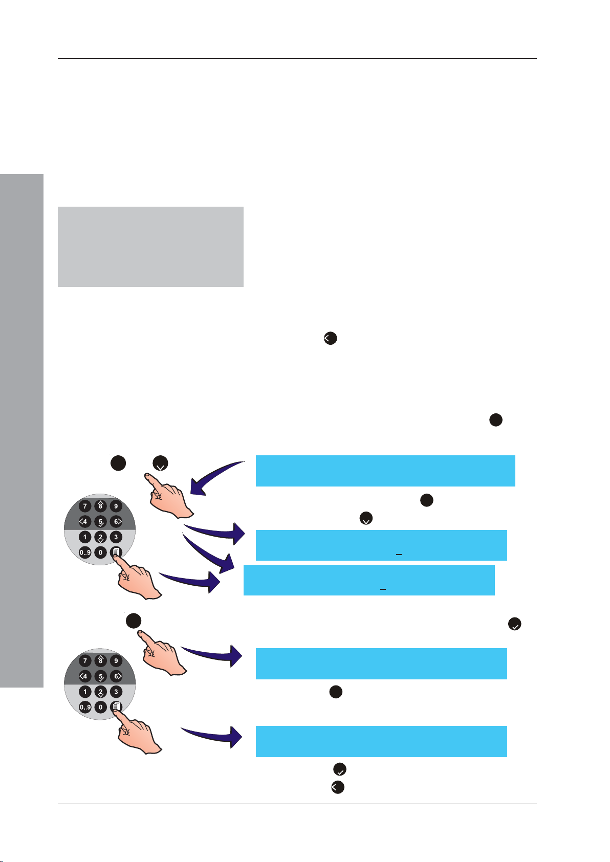
ID50 Series Panel - Installation, Commissioning & Configuration Manual
SMART 4 Devices
The mult-criteria sensor SMART 4
logical device type, depending on loop
protocol, is SM4 (CLIP) or SMT4
(OPAL).
5.6.1.2 Sensor Sensitivity Setting
This option allows the sensitivity of sensors to be changed
during device configuration. Access is via the Circuit menu.
Individual sensor Alarm and/or Day settings can be changed.
VIEWTM Sensors and SMART 4 Multi-Sensors
The ID60 Panel supports VIEWTM and SMART 4. See
Appendix 2, ID60 Single Loop Panel Differences.
Co-operative Multi-sensing Groups
The ID60 Panel supports co-operative multi-sensing through
the Advance Warning Addressable Combustion Sensing
(AWACSTM) software algorithm for the following devices:
VIEWTM, ION, OPT, MLT, OPX/SM2 (Optiplex Multi-Sensor),
SM3, SM4, (SMART 3 and 4 Multi-criteria Sensors). Once
included in the AWACSTM algorithm, the sensitivity
configuration follows that for VIEWTM device types, i.e. using
levels and not a percentage of alarm. During configuration
of the sensor sensitivity values, the LCD returns to the
previously configured value if any of the following occurs:
a. The ‘4’ button on the numeric keypad is pressed.
or
1
Configuration Mode
2
1
2
3
[Sensor nn - AAA] Sensitivity
1: Alarm (100%) 2: Day (100%) 3: Group (00)
[Sensor nn - AAA] Sensitivity
Enter new alarm level : 120 < : Cancel
[Sensor nn - AAA] Sensitivity
Enter day mode alarm : 80 < : Cancel
b. The panel state is unchanged for 1 minute.
c. A value outside the predefined operating limits (80% to
120% or L1 to L6 for OPX/SM2, SM3 or SM4) is entered.
To change the sensor sensitivity settings:
1 At the sensor attributes menu, press the ‘3’ button
on the numeric keypad to display the Sensor Sensitivity
Setting menu:
2 Using the numeric keypad, press ‘1’ to select the Alarm Sensitivity
setting or press ‘2’ to select the Day Mode Sensitivity setting:
3 At the appropriate prompt, use the numeric keypad to
enter the desired percentage value. Press ‘5’ to
confirm the value entered.
997-263-000-11, Issue 11
January 2010
[Sensor nn - AAA] Sensitivity
1: Alarm (120%) 2: Day (80%) 3: Group (00)
4 Press ‘3’ to select a new AWACS group, if required. At
the appropriate prompt, use the numeric keypad to
enter the desired AWACS group:
[Sensor nn - AAA] Sensitivity
Enter new AWACS Group : _ < : Cancel
5 Press ‘5’ to confirm the AWACS group entered or
press ‘4’ to cancel.
70
Page 75
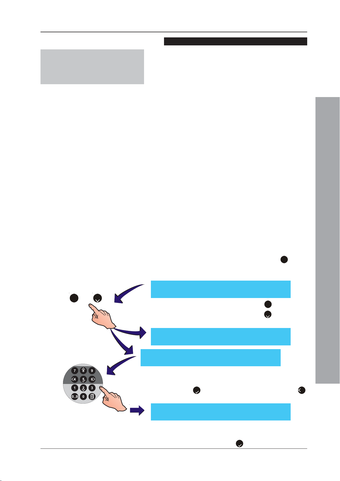
ID50 Series Panel - Installation, Commissioning & Configuration Manual
Optiplex/SM2, SMART 3 and 4 Multi-criteria Sensors
Note:
With newly-learnt multi-criteria
devices the sensitivity setting
defaults to level 5.
These sensors require smoke pre-alarm and alarm sensitivity
to be set as one of a number of available sensitivity levels. For
Optiplex/SM2 and SM3, the number of levels is dependent on
the panel type (ID50 or ID60) and whether the device is part of a
group. For SMART 4 (ID60 only) the number of levels is
dependent on whether the device is part of a group. In standalone mode five levels are available, L1 to L5, L1 being the most
sensitive and L5 being the least sensitive. In a group the range
is extended to nine levels, L1 to L9. In addition, a lower sensitivity
level, L61 (or L9 in a group), which is a heat-sensing function
only, is available for use with a configured Day Mode activity.
Optiplex (OPX) Multi-Sensors can operate in stand-alone mode
or, when used with ID60 panels, form part of a co-operative
AWACSTM group. SMART sensors can also work in stand-alone
mode or form part of a co-operative AWACSTM group.
1
OPX/SM2 and SM3 sensor level 6 functionality is only
possible with panel software version 5.00, or above. SMART
4 sensor level 6 functionality is only possible with panel
software version 5.08, or above. OPX/SM2 and SM3
sensors must only be used with LIB software version 9.00,
or above. SMART 4 sensors must only be used with LIB
software version 11.00, or above.
Note: Refer to Appendix 2 ID60 Single Loop Panel
Differences for details on setting the sensitivity level
of grouped OPX/SM2, SM3 and SM4 sensors.
or
To set the sensitivity of OPX/SM2 and SM3 sensors for
the ID50 panel (the procedure for setting the sensitivity
of SM4 sensors on the ID60 is the same):
1 At the sensor attributes menu, press the ‘3’ button
on the numeric keypad to display the Sensor Sensitivity
Setting menu:
[Sensor nn - OPX] Sensitivity
1 : Alarm(Lvl5) 2 : Day(Lvl5) 3 : Group (00)
21
2 Using the numeric keypad, press ‘1’ to select the
Alarm Sensitivity setting or press ‘2’ to select the
1
[Sensor nn - OPX] Sensitivity
2
Enter new alarm level : ____ < : Cancel
[Sensor nn - OPX] Sensitivity
Enter day mode alarm : ____ < : Cancel
Day Mode Sensitivity setting.
3 At the appropriate prompt, use the numeric keypad to
enter the desired sensitivity level.
4 Press ‘5’ to confirm the level entered or press ‘4’
to cancel.
Configuration Mode
[Sensor nn - OPX] Sensitivity
1 : Alarm(Lvl) 2 : Day(Lvl5) 3 : Group (00)
Note: In either case you will be prompted to select the
pre-alarm sensitivity level. Select a new level, if
required, and press ‘5’ to confirm.
71
997-263-000-11, Issue 11
January 2010
Page 76
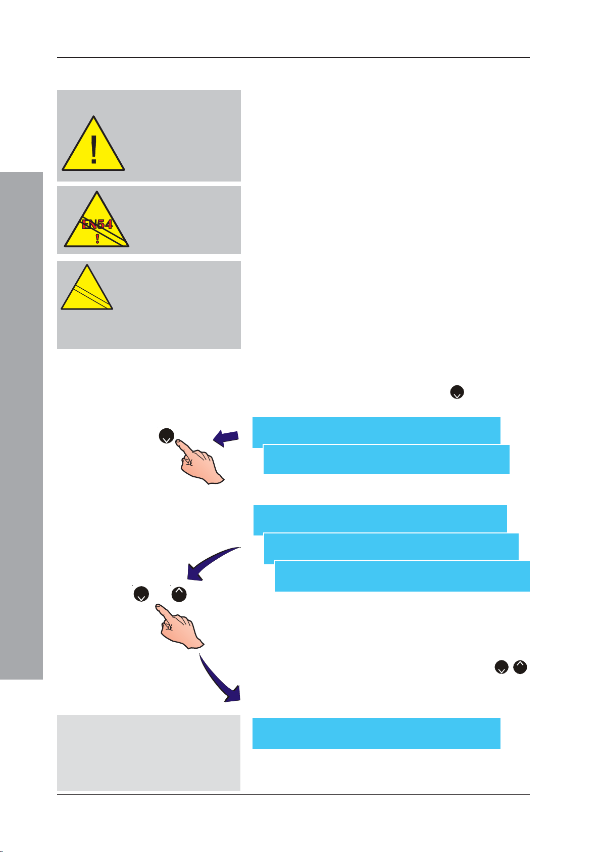
ID50 Series Panel - Installation, Commissioning & Configuration Manual
EN
12094-1
!
5.6.1.3 Type Setting
The first 30 modules (from
lowest address upwards)
restricted to types MCP, DKM,
MRL, IRL and all AUX actions
except Plant Alarm, are added
automatically to a priority poll
list. Subsequent modules are
polled normally.
EN54-2 : 7.6.1, 7.8
Level 2 Keyswitch access
MUST be used with an input
Type AUX panel Reset (7.6.1)
& Silence/Resound (7.8).
CAUTION:
This product is not compliant
EN
12094-1
!
with EN 12094-1.
Fire extinguishing installations in
Europe are required to be certified as
compliant to this standard.
Standard input modules in zones 1 to 16 can be assigned
to various types as shown below. A Manual Call Point (MCP)
input has the action of a zone fire alarm ‘Manual Call Point’
with prioritized polling. A Fire Alarm Monitor (MON) input
has the action of a zone fire alarm with non-prioritized polling.
An input module assigned to a zone in the range 17 to 32 is
automatically given the type AUX, for a plant alarm input.
Input devices of type AUX can be programmed for plant
alarm, reset panel, silence sounders, mute buzzer, class
change, (only used when Class Change input has been
configured for Day Mode start), abort switch, hold switch,
Extinguishing System released and Extinguishing System
fault (the last four cases are functions associated with
the configuration of Extinguishing System inputs).
The device type is configured during the learn process.
Sensor types and Plant Warning inputs (AUX) cannot be
changed. The ‘Type’ menu option is not shown on the
display for these devices.
Monitored output modules can be assigned to various
types as shown below.
To change the module type as displayed on the LCD:
2
[Module nn - MCP] Select Type :
>MCP< DKM MON MNS MRL IRL <: Cancel
Configuration Mode
[Module nn - MCP] 1 : Zone (nn) 2 : Type
2
1
Non-monitored outputs
2
If ‘TxD’ is selected refer to the Operating
Manual, Section 4.12.7 Voltages - User
Option to set the transmission circuit
reference impedance to enable correct
fault monitoring.
or
8
[Module nn - MCP] 1 : Zone (nn) 2 : Type
3 : CBE Rule (nn) 4 : [ Blank/Existing Text ]
1 Using the numeric keypad press ‘2’ (Type option)
from the menu displaying the module attributes:
4 : [ Blank/Existing Text ]
[Module nn - SDR] 1 : Zone (nn) 2 : Type
3 : CBE Rule (nn) 4 : [ Blank/Existing Text ]
2 Selecting the Type option displays one of the following:
[Module nn - ZMX] Select Type :
>ZMX< FRM <: Cancel
[Module nn - SDR] Select Type :
>SDR< CTL RLY EST ESO ESM TxD ESE RLE CTE S
Note: On-Board circuits 1, 2, 3 and 4 support SDR, SDH,
RLY1, CTL, TxD2, RLE1, CTE, EST1, ESO and ESE
Output Circuits. On-Board circuits 5 and 6 are fixed
as Unmonitored -VE Output circuits.
3 Select the module type using the press the ‘2/8’
buttons to cycle through the list of modules and select
the new type. The LCD then displays the new module
attributes menu. A typical menu is shown below:
1
997-263-000-11, Issue 11
January 2010
72
Page 77
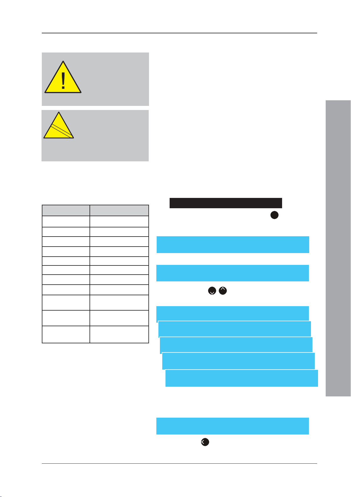
ID50 Series Panel - Installation, Commissioning & Configuration Manual
EN
12094-1
!
5.6.1.4 AUX Action
The first 30 modules (from
lowest address upwards)
restricted to types MCP, DKM,
ZMX, MRL, IRL and all AUX
actions except Plant Alarm, are
added automatically to a
priority poll list. Subsequent
modules are polled normally.
CAUTION:
This product is not compliant
EN
12094-1
!
with EN 12094-1.
Fire extinguishing installations in
Europe are required to be certified as
compliant to this standard.
AUX Actions Description
Action (PLANT) Plant Alarm
Action (RESET) Reset action
Action (SIL. ) Silence outputs
Action (MUTE ) Mute action
Action (CLASS) Class Change
Action (ABORT) Abort switch
Action (HOLD) Hold switch
Action (FBCLD) Fire Brigade Called
Action (ESREL) Extinguishing System
Released*
Action (ESFLT) Extinguishing System
Fault*
Action (FRFLT) Fault Routing
Transmission Fault**
* Monitored for short-circuit faults.
** The indication of a fault routing transmission
fault is dependent upon the third-party fault
routing equipment being configured to
provide an appropriate input.
An input device assigned to zones 17 to 32 is treated as
a Plant alarm input and given the default type of AUX.
The auxiliary action specifies which of the following
actions takes place with the operation of an AUX input:
i Plant Alarm - non-latching
ii Panel Reset
iii Silence Sounders
iv Mute Buzzer
v Class Change
vi Abort Switch - latching
vii Hold switch - non-latching
viii Fire Brigade Called
ix Extinguishing System Released
x Extinguishing System Fault
xi Fault Routing Transmission Fault
To ensure recognition by the panel, the input device must
be active for at least 5 seconds (longer if not priority-polled).
To select the required auxiliary action:
1 Using the numeric keypad, press ‘3’ at the module
edit screen to select the auxiliary ‘Action’ option (the
default action is PLANT).
[Module nn - AUX] 1: Zone (17)
3: Action (PLANT) 4:[ Blank/Existing Text ]
2 The screen displays action options as follows:
[Module nn - Action] 1: Plant Alarm
2: Reset Panel 3: Silence Sounders ¦ : More
Press the ‘2/8’ buttons to display other AUX action
options, as appropriate.
[Module nn - Action] 4: Mute Buzzer
5: Class Change 6: Abort Switch ¦ : More
[Module nn - Action] 7: Hold Switch
8: Fire Brigade Called ¦ : More
[Module nn - Action]
9: Ext. System Released ¦ : More
[Module nn - Action]
10: Ext. System Fault ¦ : More
[Module nn - Action]
11: Fault Routing Fault ¦ : More
Configuration Mode
3 Press the appropriate numeric pushbutton to select the
required action, e.g. Abort Switch. The display confirms
the selection and returns to the module edit screen:
[Module nn - AUX] 1: Zone (17)
3: Action (ABORT) 4:[ Blank/Existing Text ]
Press the ‘4’ button to exit the module edit screen.
73
997-263-000-11, Issue 11
January 2010
Page 78
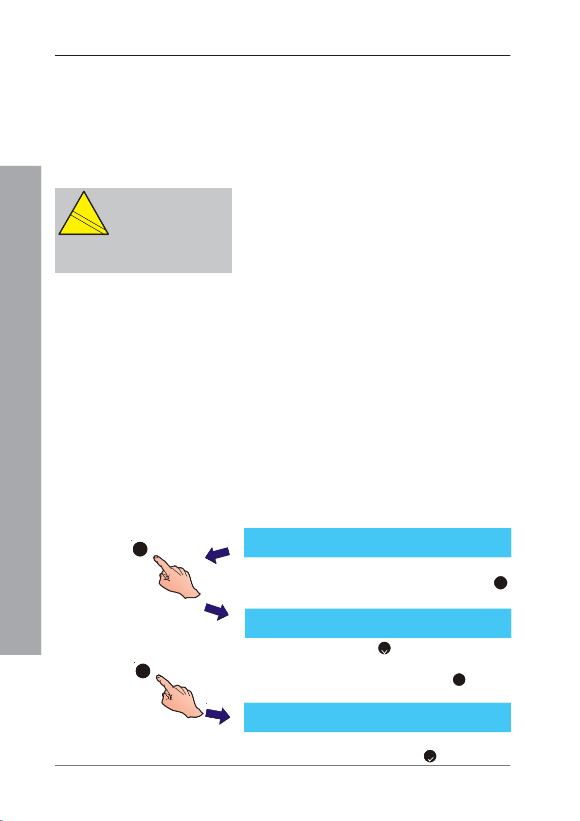
ID50 Series Panel - Installation, Commissioning & Configuration Manual
EN
12094-1
!
CAUTION:
This product is not compliant
EN
12094-1
!
with EN 12094-1.
Fire extinguishing installations in
Europe are required to be certified as
compliant to this standard.
5.6.1.5 CBE Rules
The CBE Rules option is used during the SLC Loop
configuration. It is accessed through the Commissioning
Menu. The panel can be configured with up to 64 CBE rules.
This option enables modules to be assigned to a CBE Rule.
CLIP Loop Booster Support
The Loop Booster provides the additional power needed
by high-current-draw loop devices, such as loop sounders,
when the panel goes into alarm. When performing an SLC
Learn operation, all sounder modules are automatically
allocated for loop booster support. A ‘+’ symbol, displayed
adjacent to the allocated CBE rule number, indicates that
the module will receive loop booster support (see below).
Note: if a device type is changed to one that may be loop
powered (i.e. SDR) to one that cannot (i.e. RLY),
either through manual type change or auto-learn
method, the loop-powered allocation is cleared.
Base Rule and Rule Range
Devices may be activated by any of up to 24 contiguouslynumbered CBE rules. When assigning modules to CBE rules
a Base Rule number has to be specified with an associated
rule range (up to 24 rules starting at the base rule) and the
auxiliary action. The Base Rule number and rule range apply
to AUX - Hold Switch, AUX - Abort Switch, SDR, SDH, CTL,
RLY, EST, MRL, IRL, ESO, ESE, RLE and CTE.
Configuration Mode
[Module nn - SDR] 1 : Zone (nn) 2 : Type
3
1
3 : CBE Rule (nn+) 4 : [ Blank/Existing Text ]
[Mnn] CBE Rules 01
1: Base [01 +: No ] NNNNNNNNNNNNNNNNNNNNNNNN
For input devices the range specifies which CBE rules
are affected by the input. The action taken by the CBE
rule depends on the type of input.
For outputs, the range specifies which CBE rules will affect
the output. The output takes the highest priority status from
a combination of all the CBE rules.
The Base Rule number has a valid range of 1-41 with a
default of 1. The Rule Range will default to having the first
CBE rule set only. To select or change the Rule number to
which a module is assigned:
1 With the module CBE Rules attributes screen
displayed, use the numeric keypad and press the ‘3’
button to select the CBE Rules option screen:
--------------------------------------------
Note: Press the numeric 2 to toggle the Loop Booster
support ‘+’ on or off.
2 Using the numeric keypad, press the 1 button to
change the CBE Base Rule:
24
997-263-000-11, Issue 11
January 2010
[Mnn] CBE Rules 01
Enter CBE Rule: _ < : Cancel
3 Using the numeric keypad enter the desired Base Rule,
for example Rule 6, and press ‘5’ to confirm. The
74
--------------------------------------------
24
Page 79
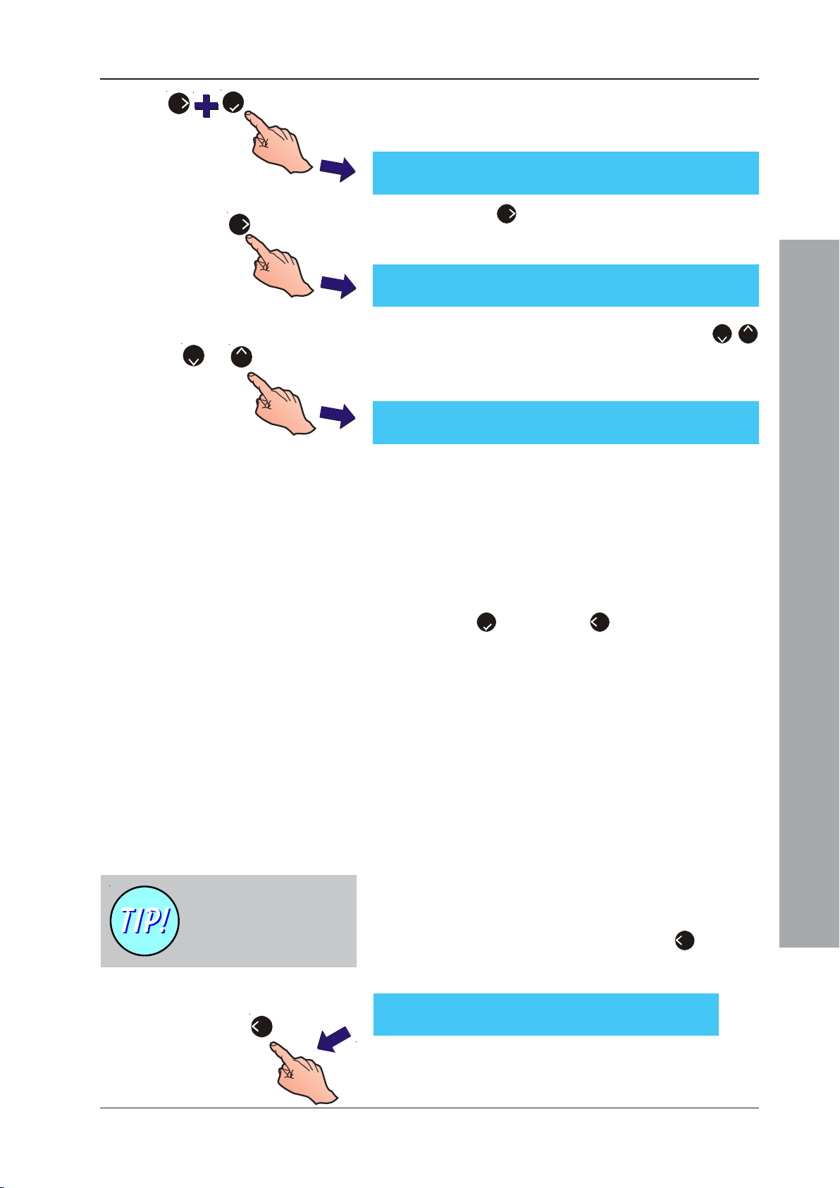
ID50 Series Panel - Installation, Commissioning & Configuration Manual
6
5
CBE Rule range on line 1 changes, now starting at
‘6’. The CBE Rule number in the square brackets on
line 2 also reflects the changed selection:
[Mnn] CBE Rules 06
--------------------------------------------
29
1: Base [06 +: No ] NNNNNNNNNNNNNNNNNNNNNNNN
6
4 Press the 6 button to move the cursor to the right -
the selected rule number is inverted and is changed
in the square brackets on line 2.
[Mnn] CBE Rules 06
--------------------------------------------
29
1: Base [13: No] NNNNNNNNNNNNNNNNNNNNNNNN
5 At the selected CBE Rule number, press the 2/
or
2
8
buttons to toggle its status between Y(es) and N(o) -
8
the change of status is confirmed in the square
brackets on line 2 as follows:
[Mnn] CBE Rules 06
--------------------------------------------
29
1: Base [13: Yes] NNNNNNNYNNNNNNNNNNNNNNNN
Continue with other CBE Rules in the same way.
Note: After changing the base rule number, the CBE
Rules attributes screen displays the first
associated rule and NOT the selected base rule
number. In the case illustrated above, the number
displayed is ‘13’ and not the base rule number
‘6’. If no rule has been assigned, no CBE rule
number is displayed.
Text Editing is always
Option 4 when device
description text can be
edited.
4
6 Press ‘5’ to confirm or ‘4’ to cancel the new CBE
Rule selection.
Other module types are selected and CBE Rules
associated in the same way as illustrated above. Return
to the ‘Modules’ selection screen as described in
Section 5.6.1 Signalling Line Circuit (SLC) - Devices.
Refer to the configuration menu option for information
on how to define the pattern (CBE Rule). The pattern
defines whether the output will respond to zonal
alarms. It also determines whether the output is
silenceable and whether any delay is interruptable.
5.6.1.6 Device Text Setting
The Device Text Setting option allows the device
description to be changed. To select the Device Text
option from the displayed menu:
1 Using the numeric keypad, press the ‘4’ button to
select the current associated device text. The following
is displayed:
[Sensor nn - AAA] 1 : Zone (nn)
3 : Sensitivity 4 : [ Blank/Existing Text ]
Configuration Mode
2 The upper line of the display shows the 20-characters
of text currently assigned to the device. The character
that can be changed flashes.
75
997-263-000-11, Issue 11
January 2010
Page 80
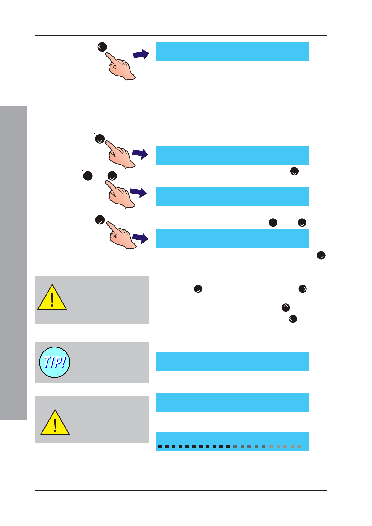
ID50 Series Panel - Installation, Commissioning & Configuration Manual
4
[Blank/Existing Text ] ¦ : Char : Done
> : Next < : Previous u1:Delete u3:Insert
Note: For further information on changing text, refer to
Section 5.8, Zone Texts.
5.6.2 Signalling Line Circuit (SLC) - Learn
This option provides automatic recognition of the devices
connected to the SLC loop. The panel searches and learns
all the devices on the loop. The panel prompts for selection
of the loop polling protocol, CLIP only or to Enable OPAL
protocol, before starting a learn operation. To perform the
2
or
1
2
5
Learn procedure:
[S1 SLC] 1 : Devices 2 : Learn
1 Using the numeric keypad, press the ‘2’ button to
select the Learn option.
[S1 LEARN] 1 : All CLIP protocol
2 : Enable OPAL protocol ¦ : More
2 Select the appropriate loop polling option. Using the
numeric keypad press either the ‘1’ or the ‘2’ button.
[SLC] Learn Devices?
OPAL devices are programmed
(initialised) by the panel as part
of a learn operation. Therefore,
when auto-configuring OPAL
devices, there is a short delay
before the progress bar is displayed.
Configuration Mode
The (S)ensor is replaced
with (M)odule when
learning modules and the
device types change
appropriately.
Optiplex (OPX/SM2), SMART 3 and
SMART 4 (ID60 only)
sensors are learnt as type
MLT. Manually change to
type OPX/SM2, SM3 or
SM4, respectively.
[LEARN] New device added : Snn ION
: Accept > : Skip 8 : Accept all < : Cancel
[LEARN] Device removed : Snn ION
: Accept > : Skip 8 : Accept all < : Cancel
[Learn] Learn in progress
3 The LCD prompts for confirmation. Press the ‘5’
key to start the Learn process.
4 One of the following is then displayed on the LCD. Press
the ‘5’ to Accept (confirm) a single device, ‘6’ to Skip
(ignore) the device and move to the next changed device
or using the numeric keypad press ‘8’ to Accept all
(confirm) changed devices. Press the ‘4’ to Cancel
and return to the learn devices prompt.
a. If learning sensors or modules that have been added
to the loop, the LCD displays the first new device.
b. If learning any removed sensors or modules, the LCD
displays the first removed device.
c. If Learning a new loop or there is no change on the
loop, the LCD displays a progress bar.
997-263-000-11, Issue 11
January 2010
76
Page 81
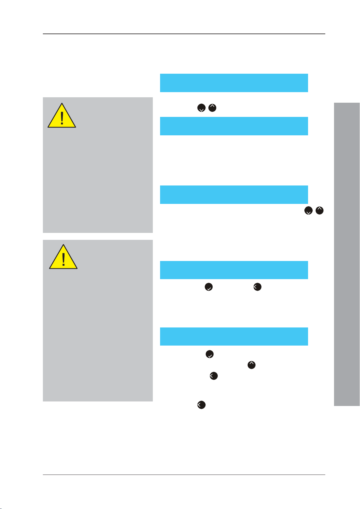
ID50 Series Panel - Installation, Commissioning & Configuration Manual
5 When completed, the LCD displays the number of
sensors or modules of each type and the total number.
a. CLIP only - the display typically shows the following
for sensors:
[LEARN] Total 021 (060 + 000) ¦ : More < : Exit
CLIP: ION 03, OPT 06, TMP 10, MLT 2
Device Missing Fault
Removing an OPAL device
will generate a ‘Device
Missing’ fault indication.
With a replacement device installed the
device will autoconfigure and continue to
operate normally.
General Notes
Replacing a device with the same or
different protocol will generate a ‘Device
Missing’ fault message. This must be
cleared using the RESET pushbutton.
A loop can be converted from one protocol
to the other. Before a loop protocol is
converted, the panel MUST be reset to
clear any latched faults.
Replacing Devices
Replacing OPAL with CLIP
- ‘Incorrect device protocol’
fault is generated.
This device is not polled thereby reducing
fire cover. If CLIP devices on loop are 10
or less, access level 3 will permit a device
re-learn and enable the panel to return to
full operational status.
If the total number of CLIP devices exceeds
10 the device will not operate and must be
replaced with a device of the same protocol
or, alternatively, at access level 3 perform
a loop re-learn as CLIP protocol.
Replacing a CLIP device with an OPAL
device - the device communicates
immediately and continues to operate
normally as a replacement CLIP device.
However, this device may be re-learnt as
an OPAL device at access level 3.
b. CLIP only - To view the other learnt CLIP devices use
the ‘2/8’ buttons to scroll down or up:
[LEARN] Total 039 (060 + 000) ¦ : More < : Exit
CLIP: MCP 30, MON 02, SDR 05, CTL 02
c. If the option ‘Enable OPAL protocol’ was selected the
total of all OPAL and any CLIP devices learnt is
displayed; the numeric value before the brackets is the
total of all loop devices, by sensor or module, for the
indicated protocol, whilst the numbers in brackets are
totals for: first the CLIP devices and then OPAL devices.
[LEARN] Total 010 (003 + 007) ¦ : More < : Exit
OPAL: OPT 03, SM2 02, SM3 01, M701 01
To view the other learnt devices use the ‘2/8’
buttons to scroll down or up.
Note: Selecting menu option 3 Display Totals, shows the
current summary display.
6 If a duplicate device address is detected the following
screen is displayed:
[LEARN] Multiple address detected : Snn
: Continue < : cancel
Press ‘5’ to confirm or ’4’ to cancel.
7 If the loop protocol is changed, from OPAL to CLIP or
vice versa, or a replaced device has been installed
followed by a learn operation, the following message is
displayed:
[LEARN] Protocol Changed : Snn SM3
: Accept > : Skip 8 : Accept all < : Cancel
Press ‘5’ to re-configure the device or using the
numeric keypad press ‘8’ to re-configure all devices
or press ’4’ to leave cancel action and leave as CLIP
protocol mode.
8 When the Learn procedure has been completed, press
the ‘4’ button to return to the Learn Devices menu.
Configuration Mode
77
997-263-000-11, Issue 11
January 2010
Page 82
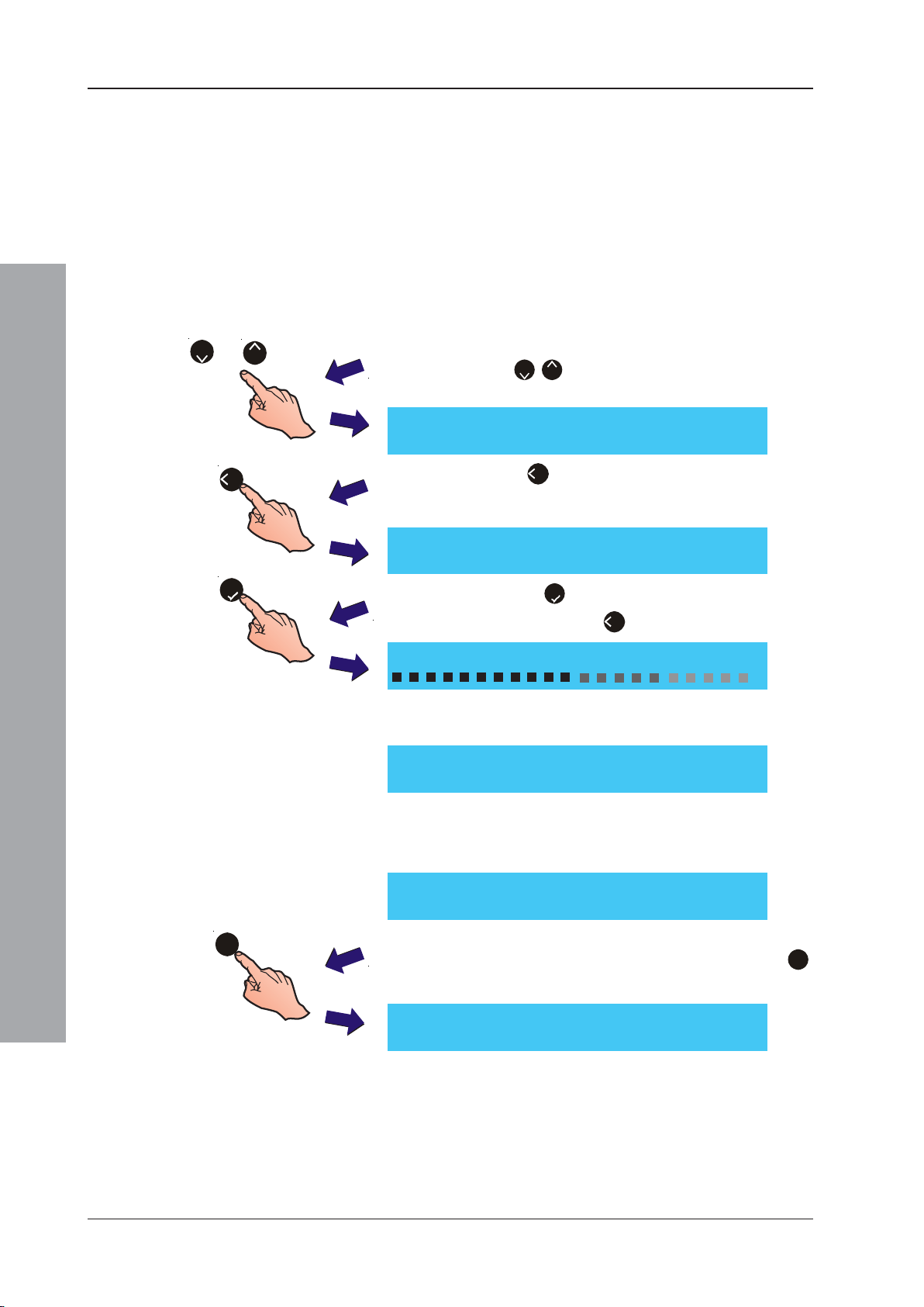
ID50 Series Panel - Installation, Commissioning & Configuration Manual
5.6.2.1 Initialising OPAL Devices
OPAL protocol loop devices need programming, or
initialising, before the panel can perform a learn operation
and permit device polling. Device initilialisation is normally
performed as part of a learn operation. However,
initialisation can be carried out independently of a learn
operation, for example after the replacement of a loop
device, as described below.
Also, it is possible to display the loop device totals,
normally displayed after a learn operation, using the
LEARN menu option ‘4: Display Totals’.
2
or
8
1 Use the ‘2/8’ buttons to scroll to the second menu
display.
[S1 LEARN] 3 : Display Totals
4 : Initialise OPAL ¦ : More
4
[LEARN] Confirm OPAL Device Initialise
5
[Learn] Initialising OPAL Devices
[S1 LEARN] 3 : Display Totals
Configuration Mode
[LEARN] No OPAL Devices Configuration
2 Press the ‘4’ pushbutton using the numeric keypad
to select ‘Initialise OPAL’. A request for initialise
confirmation is then displayed:
: Continue <: Cancel
3 Press the ‘5’ pushbutton to confirm device
initialisation or press ‘4’ to cancel:
4 When initialisation is complete the second menu
screen is re-displayed:
4 : Initialise OPAL ¦ : More
Note: If this option is selected before a learn operation is
carried out or with a CLIP protocol loop the
following error message is displayed:
<: Exit
3
997-263-000-11, Issue 11
January 2010
5 To re-display the learn totals after an initialise
operation, use the numeric keypad and press the ‘3’
button to select the option ‘Display Totals’:
[LEARN] Total 010 (003 + 007) ¦ : More < : Exit
OPAL: OPT 03, SM2 02, SM3 01, M701 01
78
Page 83
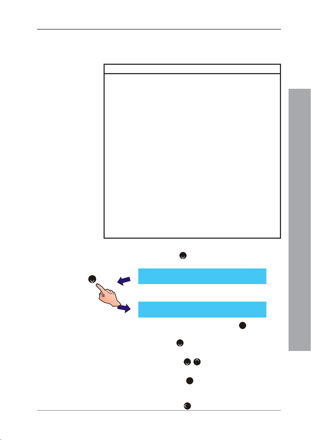
ID50 Series Panel - Installation, Commissioning & Configuration Manual
5.6.3 On-Board Circuits
This option permits configuration of the On-Board Output
Circuits. There are six output circuits as defined in the
following table:
Output No. Type Description
1 (B01) Fixed Monitored Monitored Sounder (SDR or SDH) or Monitored Control
2 (B02) Fixed Monitored Monitored Sounder (SDR or SDH) or Monitored Control
3 (B03) Hardware Configurable Can be configured for operation as a Monitored Output
4 (B04) Hardware Configurable Can be configured for operation as a Monitored Output
5 (B05) -VE Output Circuit (1) Unmonitored Output Circuit. Can be programmed for Fire
6 (B06) -VE Output Circuit (2) Unmonitored Output Circuit. Can be programmed for Fire
Output Circuit (A) Module (CTL) or Transmission Device (TxD) can be
programmed for Fire Alarm, Fault, Pre-Alarm, Plant
Warning or Extinguishing System CBE Rules.
Factory Default = Fire Alarm - All Zones.
Output Circuit (B) Module (CTL) can be programmed for Fire Alarm, Fault,
Pre-Alarm, Plant Warning or Extinguishing System CBE
Rules.
Factory Default = Fire Alarm - All Zones.
CFG Output Circuit (C) (Sounder Circuit or Relay Circuit) or as an Unmonitored
Output (volt-free style relay Circuit).
Can be programmed for Fire Alarm, Fault, Pre-Alarm,
Plant Warning or Extinguishing System CBE Rules.
Factory Default = Unmonitored Relay.
CFG Output Circuit (D) (Sounder Circuit or Relay Circuit) or as an Unmonitored
Output (dry-contact style relay Circuit).
Can be programmed for Fire Alarm, Fault, Pre-Alarm,
Plant Warning or Extinguishing System CBE Rules.
Factory Default = Unmonitored Relay.
Alarm, Fault, Pre-Alarm, Plant Warning or Extinguishing
System CBE Rules.
This output is normally used to drive an external relay.
Factory Default = General Pre-Alarm
Alarm, Fault, Pre-Alarm, Plant Warning or Extinguishing
System CBE Rules.
This output is normally used to drive an external relay.
Factory Default = Plant Warning
To change the On-Board Output CBE rule:
1 Press ‘2’ on the numeric keypad, select the
On-Board menu from the Circuit Menu below.
[S1 Circuit] 1 : SLC Loop 2 : On-Board
2
Configuration Mode
2 The display then shows the following menu. Select
the appropriate action:
[ON-BOARD] B01 (SDR) 3: Mon. : RES.
1 : Type 2 : CBE Rule (01) ¦ : Change < : Exit
a. Using the numeric keypad press ‘1’ to change the
Type of output, or
b. Press ‘2’ on the numeric keypad to change the CBE
Rule with which the On-board output is associated.
c. Use the ‘2/8’ to change the On-board output
number and its associated CBE Rule.
d. Press the ‘3’ on the numeric keypad to toggle the
monitoring end-of-line device type: resistor (default
setting) or diode.
e. Press the ‘4’ to Cancel and return to the Circuit menu.
79 997-263-000-11, Issue 11
January 2010
Page 84
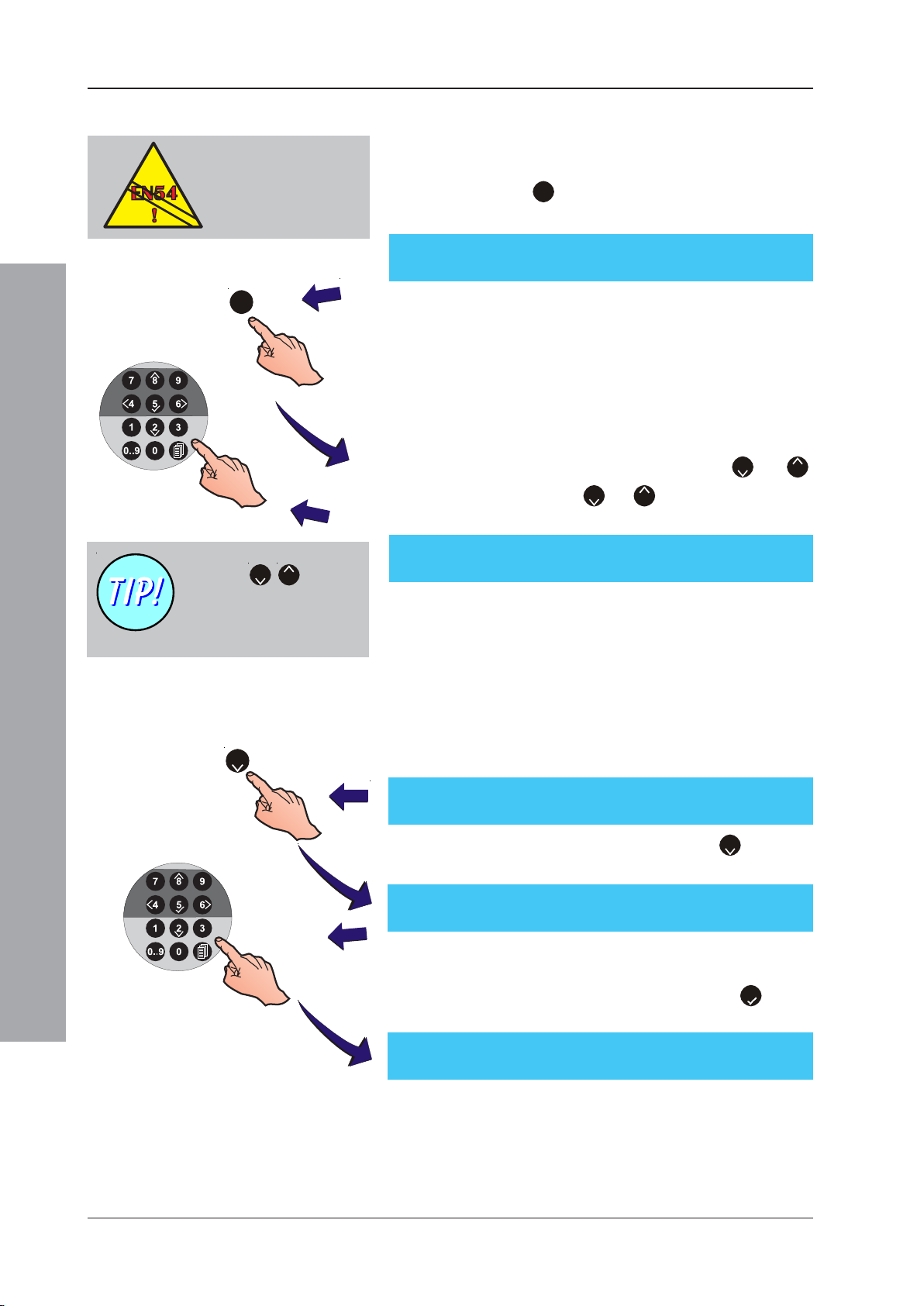
ID50 Series Panel - Installation, Commissioning & Configuration Manual
5.6.3.1 Output Type Setting
EN54-2 : 7.8
Always configure one
output as a monitored
sounder circuit to ensure
EN54 compliance
1
Use the ‘2/8’ buttons
to change the output circuit
being configured or to
change the output type.
This option allows the configuration of the panel’s onboard output circuits. To change the configuration:
1 Press the ‘1’ button on the numeric keypad. The
LCD prompts for the selection of an output type:
[ON-BOARD] B01 (SDR) 3: Mon. : RES.
1 : Type 2 : CBE Rule (01) ¦ : Change < : Exit
Note: The options are Monitored Output Circuit Sounder
(SDR - default setting), High-load Monitored Output
Circuit Sounder (SDH), Transmission Device (TxD),
Monitored Output Circuit Relay (CTL), Monitored
Output Circuit Relay1 (CTE), Unmonitored Output
Circuit (RLY), Unmonitored Output Circuit1 (RLE)
and extinguishing system output types (EST, ESO,
ESE).
2 To select the sounder circuit press the ‘2’ or ‘8’
buttons. Press the ‘2’ or ‘8’ buttons also to change
the output type.
[ON-BOARD] B01 (SDR)
>SDR<RLY CTL TxD RLE CTE EST ESO ESE S
Note: Only those types valid for the chosen output are
available. The panel’s -VE Outputs (B05/B06) are
unmonitored and are thus fixed as type ‘RLY’.
5.6.3.2 CBE Rule Setting
2
[ON-BOARD] B0n (AAA) 3: Mon. : RES.
1 : Type 2 : CBE Rule (nn) ¦ : Change < : Exit
Configuration Mode
[BOn] CBE Rules 01--- -------------------16
1 : Base [01 : No] YYYYYYYYYYYYYYYY
[BOn] CBE Rules 01-----------------------24
Enter CBE Rule : _ <: Cancel
This option allows each of the panel’s on-board output
circuits to be assigned to a CBE Rule range. Refer to
Section 5.6.1.5 CBE Rules for more details on range setting.
To change the CBE Base Rule, proceed as follows:
1 Using the numeric keypad press the ‘2‘ button to
select the CBE Rule option:
2 You are now prompted to enter a new CBE Base Rule.
Use the numeric keypad to enter the CBE Rule
required for the output circuit and use the ‘5’ button
to confirm the selection.
Refer to Section 5.7, Control-by-Event Output
Rules for information concerning the CBE Rules. The
rule defines whether the output will respond to zonal
alarms and/or the END DELAYS / EVACUATE
pushbutton. It also determines whether the output is
silenceable and whether any delays are interruptable.
January 2010
80997-263-000-11, Issue 11
Page 85
ID50 Series Panel - Installation, Commissioning & Configuration Manual
5.7 Control-By-Event Output Rules
This menu allows the configuration and viewing of the
64 Control-By-Event (CBE) Output Rules available to
the commissioning engineer. CBE Rules 1 to 7 are
pre-defined (see below for further information).
Each rule (including those that are pre-defined) can be
modified and applied to On-Board Outputs and loop
Output Modules (e.g. SDR, RLY, CTL, TxD). Each output
is referred to as an assigned output. All relevant CBE
rule information is shown on one display, as follows:
a. A Fire rule. This CBE rule type activates assigned
CBE 01 [FIRE ][ANY] 1--------------------16
1 : Change [EvSlln ] YYYYNNYYNDDNCCNN
b. A Pre-Alarm rule. This CBE rule type activates
CBE 02[PRE-ALARM ][ANY]
1 : Change [ Sl ]
c. A Plant Warning rule. This CBE rule type activates
CBE 03 [PLANT ] 1 7-------------------32
1 : Change [ ] YYYYNNYYNDDNCCNN
outputs in response to fire alarms in specified
zones. Individual zones can be modified to
determine the output response.
assigned outputs in response to a general prealarm condition at the panel.
assigned outputs in response to plant alarms in
specified zones. Individual zones can be modified
to determine the output response.
d. A Fault rule. This CBE Rule type activates
CBE 04 [FAULT ][ANY]
1 : Change
EN54-2 : 8.2.4 g)
If a fault-routing output is
configured, a fault-routing
output transmission circuit
fault indication must be
provided.
CBE 05 [FTR ]
1 : Change
CBE 06 [DISABLE ]
1 : Change
CBE 07 [RESET ]
1 : Change
CBE nn [INPUTS ] Dv1 Dv2 Dv3
1 : Change [EvSl ] S01 --- M05
CBE nn [DAY MODE]
1 : Change
CBE nn [EXTSYSTEM] Sk Tmr 1--------------16
1 :Change [Smoke/Heat] YYYYNNYYNDDNNNN
e. A Fire Output/Transfer rule. This CBE Rule type
f. Disable rule. This CBE Rule type activates
g. A Reset rule. This CBE Rule type activates
The following rules are not pre-defined and are only
selectable via the ‘Change’ option.
a. A Device Input rule. Determines the output
b. A Day Mode rule. This CBE Rule type activates
c. An Extinguishing System rule. This CBE Rule type
assigned outputs in response to a general fault
condition at the panel.
Note: The FAULT OUTPUT: FAULT/DISABLE LED,
if configured (non-default), can be programmed
to indicate a fault routing equipment fault using
a loop-based output module.
activates assigned outputs in response to the
operation of the Fire Output/Transfer relay.
Configuration Mode
assigned outputs in response to a general
disablement.
assigned outputs for 5 secs in response to a panel
reset.
response to up to three (3) specified input devices
(modules or sensors). An input from any of the
specified devices will turn on the assigned outputs.
Refer to Section 5.7.9, CBE Rules: Device Inputs.
assigned outputs when the panel is operating in
Day Mode.
activates extinguishing release system(s) in
response to fire alarm inputs in specified zones.
81 997-263-000-11, Issue 11
January 2010
Page 86
ID50 Series Panel - Installation, Commissioning & Configuration Manual
d. Thermal Mode rule (ID60 only). This CBE rule activates
CBE nn [THERMAL][ANY] 1--------------------16
1 : Change [EvSlln ] YYYYNNYYYYYNYYNN
e. Extinguishing System - System Fault. This CBE
CBE nn [ES SYSFLT]
1 : Change
Each of the CBE Output Rules has various configurable
states available, dependent on the rule type. These states
are described below:
a. Filter-by-type - options are ANY (all types), OTI
(Optical, Thermal, Ionisation, MULTI /OPX/SM2, SM3
or SM4 [ID60 only] sensor), AVS (ID60 only - see
Appendix 2), MCP (manual call point), MON (monitor
module). Extinguishing System options are
Smoke/Heat, Sensor/MCP, VIEW/Sensor, Any Two
Zones, Any Two Sensors, Any Single Sensor and Any
Single Module. Output will only operate if the input is
received from a device of the selected type.
b. Evacuate (EV) - has two options Yes (Y) or No (N). If
set to Y(es) assigned outputs activate when the END
DELAYS/EVACUATE pushbutton is operated. Outputs
will not operate when this option is set to N(o).
assigned outputs when the thermal element of multi-criteria
devices (OPX/SM2, SM3 and SM4) goes into alarm.
rule lights the Extinguishing System Fault LED, if
provided, when a PLANT Alarm zone, with AUX
action EXT. SYSTEM FAULT, has been activated.
EN54-2 : 7.11.d.
Configured delays MUST
be set to interruptable
(Y) to remain EN54
compliant.
Configuration Mode
c. Silenceable (SL) - has two options Yes (Y) or No
(N). If set to Y(es) assigned outputs will silence when
the SILENCE / RESOUND pushbutton is operated.
If set to N(o) the outputs will only silence after being
activated when the RESET pushbutton is operated.
d. Interruptable (IN) - has two options Yes (Y) or No (N). If set
to Y(es) operating the END DELAYS/EVACUATE pushbutton
cancels currently operating delays and assigned outputs
activate. If set to N(o), delays are NOT interruptable. The
delays can only be cancelled by another qualifying alarm
condition. This configuration does not comply with EN54
regulations.
e. Class Change (Cl) - has two options, Yes (Y) or No
(N). If digital input 1 is set to Class Change (see
Section 5.5.3.4) and the CBE Class Change option
is set to Y(es), then the assigned outputs operate
when digital input 1 is made. If set to N(o), digital input 1
(set to Class Change) does not operate the assigned
outputs.
f. Two Zone (Tz) - has two options Yes (Y) and No (N).
If set to Y(es), at least two zones must be active
before the CBE rule is triggered.
g. Zones - determines the output response to fire or
plant alarms on a zone by zone basis using two
options: Zones 01 to 16 and Zones 17 to 32.
January 2010
i Zones 01 to 16 - addresses the Fire rule silence
options. Each zone can be configured as:
• N(o) - the zone is NOT included in the CBE Rule,
outputs will NOT be activated.
• Y(es) - the zone is included in the CBE Rule. An alarm
in this zone activates the outputs immediately.
82997-263-000-11, Issue 11
Page 87
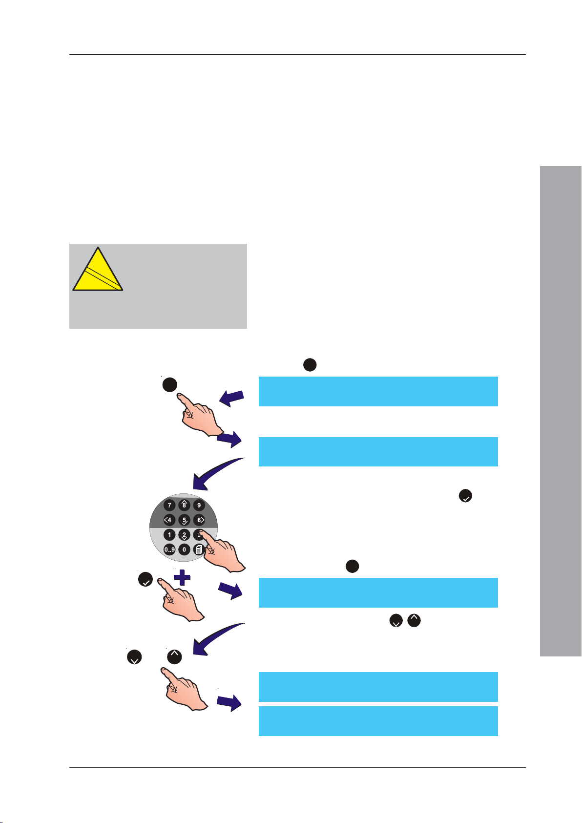
ID50 Series Panel - Installation, Commissioning & Configuration Manual
EN
12094-1
!
CAUTION:
This product is not compliant
EN
12094-1
!
with EN 12094-1.
Fire extinguishing installations in
Europe are required to be certified as
compliant to this standard.
• (D)elay - the zone is included in the CBE Rule. An
alarm in this zone will activate outputs after a delay.
Not available for Fire rules if Two Zone is selected.
Extinguishing System rules default to Delay.
• (C)oincidence - the zone is included in the CBE Rule.
Two alarms in this zone will activate outputs.
• (P)ulsed - the zone is included in the CBE Rule. An
alarm in this zone will activate outputs immediately
in pulsed mode. This mode is overridden if an alarm
occurs in any zone that is included in this rule and for
which Pulse Mode is not selected, also if a device is
assigned to multiple CBE rules and a rule for which
Pulse Mode is not selected becomes active.
ii Zones 17 to 32 - addresses the plant warning rule
silence options. These zones can be configured in
the same manner as described for zones 01 to 16.
h. Soak Timer (Sk Tmr) - has two options Yes (Y) or
No (N). If set to Y(es) the associated extinguishing
output is active only for the time specified in the
System Soak Timer Setup menu.
To select the CBE Rule menu, proceed as follows:
1 With the Commissioning menu displayed, press the
‘3’ button on the numeric keypad.
3
5
[S1 COMM] 1 : Setup 2 : Circuit
3 : CBE Rules 4 : Zones 5 : Access ¦ : More
2 The LCD prompts you to enter a CBE Rule number
as shown below:
[CBE Rule] Select Rule No ____
Enter the required CBE Rule number using the numeric
keypad and confirm by pressing the ‘5’ button.
3 The LCD then displays the selected CBE Rule’s current
configuration and a menu option to allow changes to
the rule. The displayed configurable options depend
upon the rule type. To change the rule configuration
press the ‘1’ button on the numeric keypad.
CBE 01[FIRE ][ANY] 1--------------------16
1 : Change [EvSlln ] YYYYNNYYNDDNCCNN
Note: You can use the ‘2/8’ buttons to step through
each of the 64 CBE Rules.
Configuration Mode
or
82
4 At the menu below, use the numeric keypad to select
the option that requires changing.
CBE Rule:01 1:Type 2:Filter 3:Evac
4:Silence 5:Interrupt ¦ : More
CBE Rule:01 6:Class Change 7:Two Zone
9:Zones ¦ : More
Note: Selectable options are dependent upon the type
of the current CBE Rule.
83 997-263-000-11, Issue 11
January 2010
Page 88
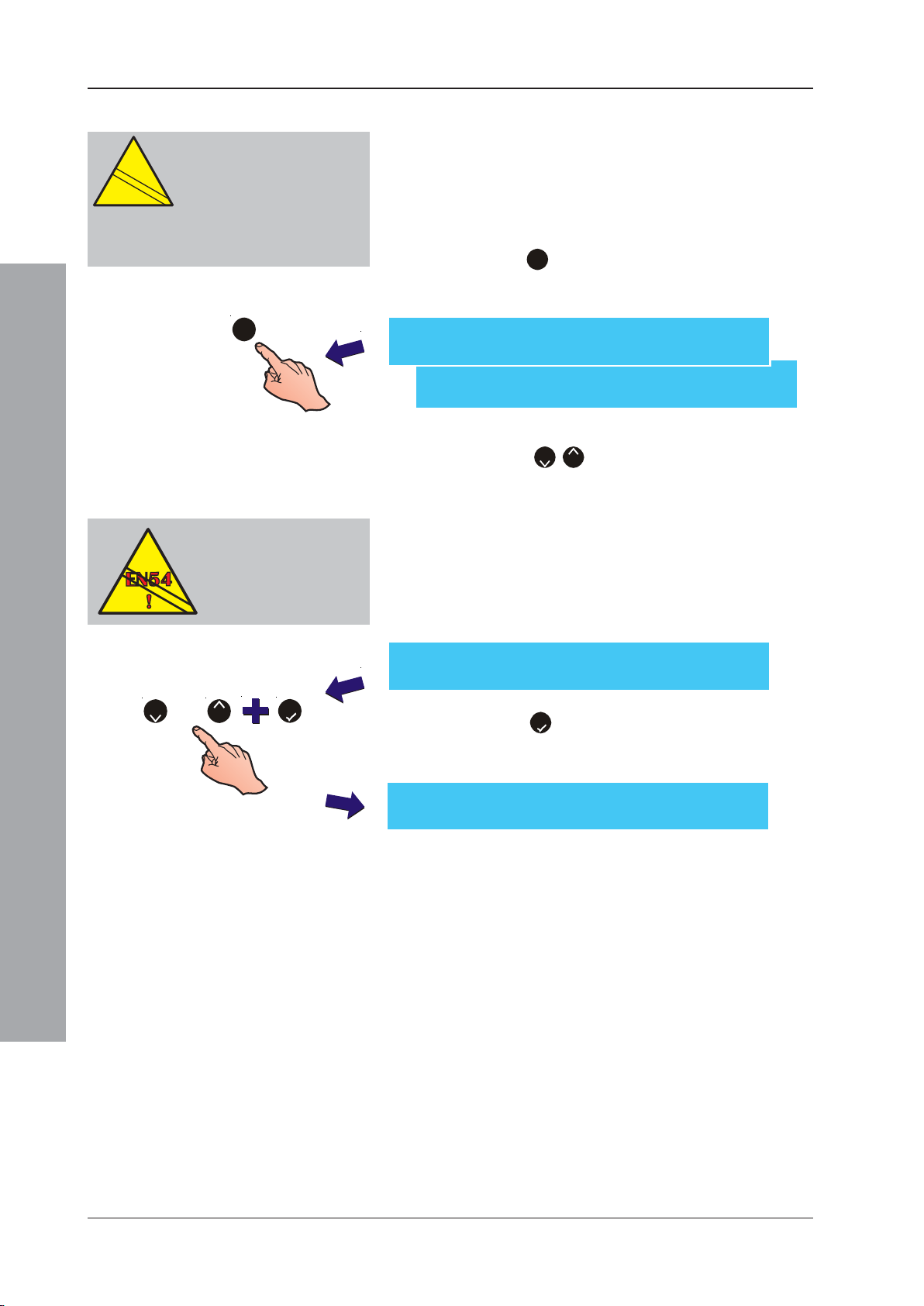
ID50 Series Panel - Installation, Commissioning & Configuration Manual
EN
12094-1
!
5.7.1 Output Type
CAUTION:
This product is not compliant
EN
12094-1
!
with EN 12094-1.
Fire extinguishing installations in
Europe are required to be certified as
compliant to this standard.
1
EN54-2 : 8.2.4 g)
If a fault-routing output is
configured, a fault-routing
output transmission circuit
fault indication must be
provided.
Twelve (12) CBE Output Rule types are available. This
menu allows the type to be selected. The current
attributes of the selected Rule are displayed and can be
edited. To change the Rule type, from the CBE Output
Rules menu proceed as follows:
1 Press the ‘1’ button on the numeric keypad to select
the Type option from the menu. The LCD displays
the Type menu:
CBE Rule:01 1:Type 2:Filter 3:Evac
4:Silence 5:Interrupt ¦ : More
CBE Rule:01 6:Class Change 7:Two Zone
9:Zones ¦ : More
2 Using the ‘2/8’ buttons, step through the CBE
Output Rule types until the required type is displayed
on the upper line, i.e. FIRE, INPUTS, FAULT, PREALARM, PLANT, FTR (Fire Transmission Relay),
RESET, DAY MODE, EXT SYSTEM, DISABLE,
THERMAL, ES SYSFLT (ES System Fault).
Note: If a fault-routing output is configured, a fault-
routing output indication must be configured - refer
to Section 5.5.1.5 LED 2C Mode.
CBE Rule:01 Current Type = [FIRE ]
or
2
8
5
CBE 01[FIRE ][ANY] 1--------------------16
Configuration Mode
1 : Change [EvSlln ] YYYYNNYYNDDNCCNN
¦ : Change Rule Type : Accept < : Cancel
3 Press the ‘5’ button to confirm selection. The LCD
displays only the appropriate editable settings for the
selected rule, for example:
To change any of the settings on the CBE Output Rules
refer to Sections 5.7.2 Filter-by-type, 5.7.3
Evacuation, 5.7.4 Silence, 5.7.5 Interrupt Delay, 5.7.6
Class Change, 5.7.7 Two Zone, 5.7.8 Zones, 5.7.9
Device Inputs and 5.7.10 Soak Timer.
84997-263-000-11, Issue 11
January 2010
Page 89
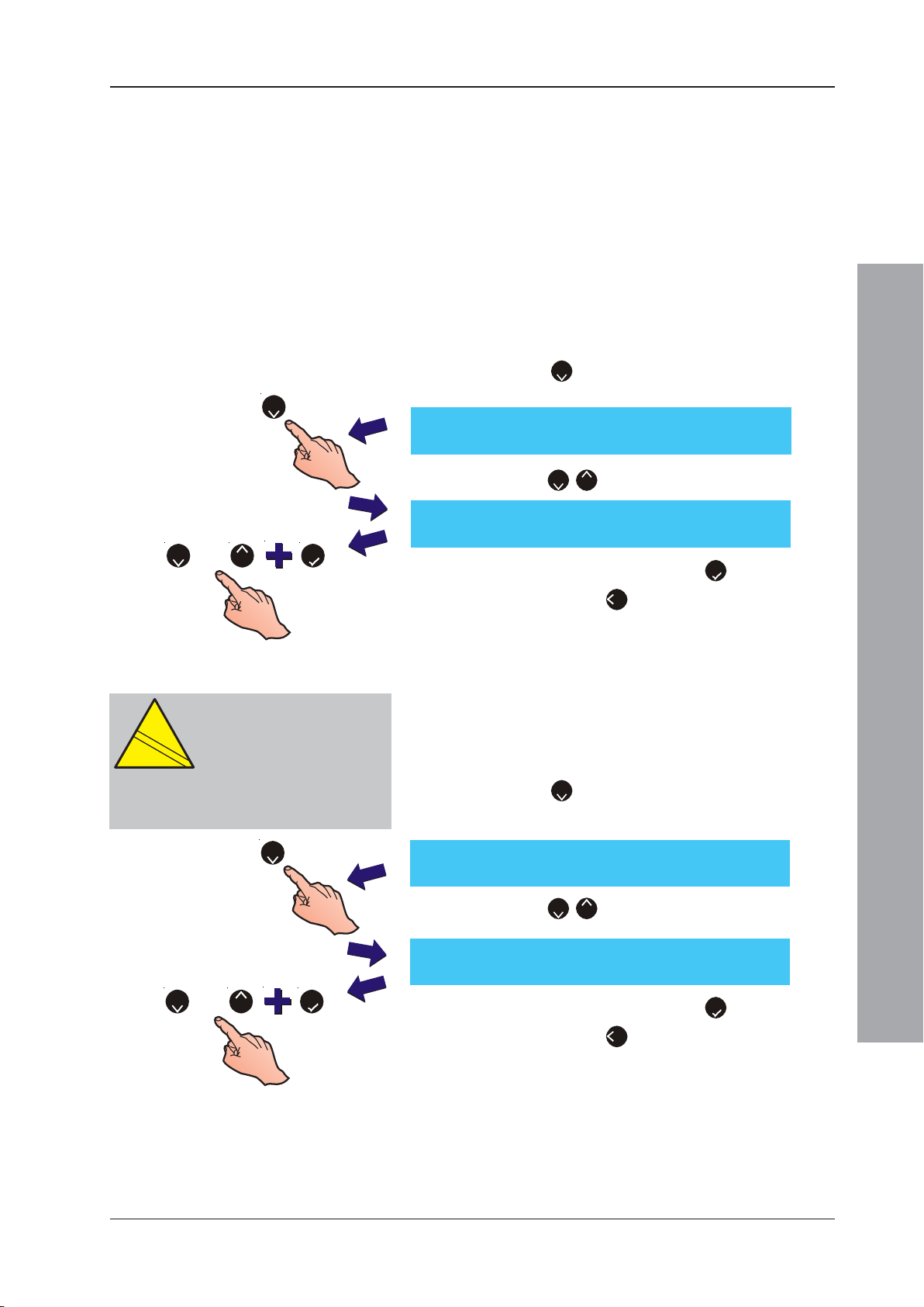
ID50 Series Panel - Installation, Commissioning & Configuration Manual
EN
12094-1
!
5.7.2 Filter-by-Type
This option is available with the Fire, Fault, Pre-alarm
and the Extinguishing System rules. The Filter-by-type
option has five selections with Fire and Fault categories:
ANY, OTI, AVS, MCP and MON and three with Pre-alarm:
ANY, OTI and AVS. The Filter-by-type option, when used
with the Extinguishing System category has seven
selections: Smoke/Heat, Sensor and MCP/ZMX, VIEW/
Sensor, Any Two Zones, Any Two Sensors, Any Single
Sensor and Any Single Module. Refer to Section 5.7,
Control-by-Event Output Rules for further information.
To select the type filter for Fire, Fault or Pre-alarm:
1 Press the ‘2’ button (using the numeric keypad) to
select the Filter option from the menu below.
2
CBE Rule:01 1:Type 2:Filter 3:Evac
4:Silence 5:Interrupt ¦ : More
2 Press the ‘2/8’ buttons to select the required filter.
CBE Rule:01 Current Filter Type =[ANY]
: Accept ¦ : Change Filter Type < : Cancel
or
82
5
3 Confirm the selection by pressing the ‘5’ button. To cancel
CAUTION:
This product is not compliant
EN
12094-1
!
with EN 12094-1.
Fire extinguishing installations in
Europe are required to be certified as
compliant to this standard.
2
or
2
8
5
the selection, press ‘4’ button.
Extinguishing System
To select the type filter for Extinguishing System:
1 Press the ‘2’ button (using the numeric keypad) to
select the Filter option from the menu below.
CBE Rule: 01 1:Type 2:Filter
8:Soak Timer 9:Zones
2 Press the ‘2/8’ buttons to select the required filter.
CBE Rule:nn Ext. System Filter = [One sensor]
: Accept ¦ : Change Filter Type < : Cancel
3 Confirm the selection by pressing the ‘5’ button. To cancel
the selection, press ‘4’ button.
Configuration Mode
85 997-263-000-11, Issue 11
January 2010
Page 90
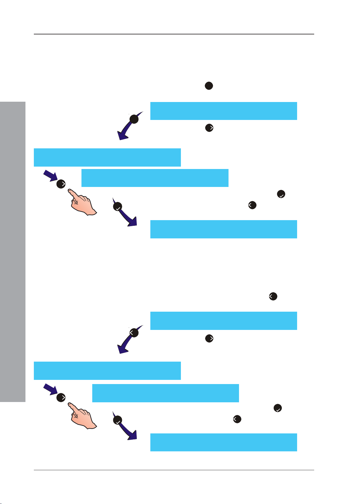
ID50 Series Panel - Installation, Commissioning & Configuration Manual
5.7.3 Evacuation
The Evacuation option has two states, Yes (Y) and No
(N). This option is available with the Fire, Pre-Alarm and
Device Inputs rules. To change the Evacuation setting:
1 Press the ‘3’ button (using the numeric keypad) to
CBE Rule:01 1:Type 2:Filter 3:Evac
3
CBE Rule:01 Evacuate = [Y]
>:Change :Accept < : Cancel
CBE Rule:01 Evacuate = [N]
6
>:Change :Accept < : Cancel
4:Silence 5:Interrupt ¦ : More
2 Press the ‘6’ button to select the required setting.
3 Confirm the selection by pressing the ‘5’ button. To
select the Evacuation option from the menu below.
Refer to Section 5.7, Control-By-Event Output
Rules for further information.
5
CBE Rule:01 1:Type 2:Filter 3:Evac
5.7.4 Silence
Configuration Mode
4
CBE Rule:01 Silence = [N]
>:Change :Accept < : Cancel
CBE Rule:01 1:Type 2:Filter 3:Evac
cancel the selection, press ‘4’ button. In either case
the menu below is re-displayed.
4:Silence 5:Interrupt ¦ : More
The Silence option has two states, Yes (Y) and No (N).
This option is available with the Fire, Pre-Alarm and
Device Inputs rules. To change the Silence setting from
the CBE Output Rules menu:
1 Using the numeric keypad, press ‘4’ to select the
Silence option from the menu below.
4:Silence 5:Interrupt ¦ : More
2 Press the ‘6’ button to select the required setting.
Refer to Section 5.7, Control-By-Event Output
Rules for further information.
6
January 2010
CBE Rule:01 Silence = [Y]
>:Change :Accept < : Cancel
3 Confirm the selection by pressing ‘5’. To cancel
5
CBE Rule:01 1:Type 2:Filter 3:Evac
the selection, press ‘4’ button. In either case the
menu below is re-displayed.
4:Silence 5:Interrupt ¦ : More
86997-263-000-11, Issue 11
Page 91
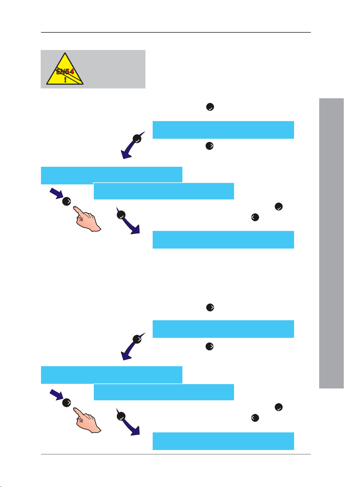
ID50 Series Panel - Installation, Commissioning & Configuration Manual
5.7.5 Interrupt Delay
EN54-2 : 7.11.d.
Configured delays MUST
be set to interruptable
(Y) to remain EN54
compliant.
5
CBE Rule:01 Interrupt = [N]
>:Change :Accept < : Cancel
CBE Rule:01 Interrupt = [Y]
>:Change :Accept < : Cancel
6
5
The Interrupt Delay option has two settings, Yes (Y) or
No (N). This option is only available with the Fire rule.
Caution: Selecting ‘No’ contravenes the
To change the Interrupt setting from the CBE Output
Rules menu:
1 Press the ‘5’ button using the numeric keypad to
CBE Rule:01 1:Type 2:Filter 3:Evac
4:Silence 5:Interrupt ¦ : More
2 Press the ‘6’ button to select the required setting.
3 Confirm the selection by pressing the ‘5’ button. To
requirements of EN54.
select the Interrupt option.
Refer to Section 5.7, Control-by-Event Output
Rules for further information.
cancel the selection, press ‘4’. In either case the
menu below is re-displayed.
CBE Rule:01 1:Type 2:Filter 3:Evac
4:Silence 5:Interrupt ¦ : More
5.7.6 Class Change
This control parameter has two options, Yes (Y) and No
(N). These indicate whether or not the selected CBE
Rule’s assigned outputs activate when Digital Input 1 is
configured as Class Change and then operated. To
configure Class Change, from the CBE Output Rules menu:
1 Press the ‘6’ button using the numeric keypad to
CBE Rule:01 6:Class Change 7:Two Zone
6
2 Press the ‘6’ button to select the required setting.
CBE Rule:01 Class Change = [N]
> : Change : Accept < : Cancel
CBE Rule:01 Class Change = [Y]
> : Change : Accept < : Cancel
6
5
3 Confirm the selection by pressing the ‘5’ button. To
Configuration Mode
select the Class Change option.
9:Zones ¦ : More
Refer to Section 5.7, Control-by-Event Output
Rules for further information.
cancel the selection, press ‘4’. In either case the
menu below is re-displayed.
CBE Rule:01 6:Class Change 7:Two Zone
9:Zones ¦ : More
87 997-263-000-11, Issue 11
January 2010
Page 92
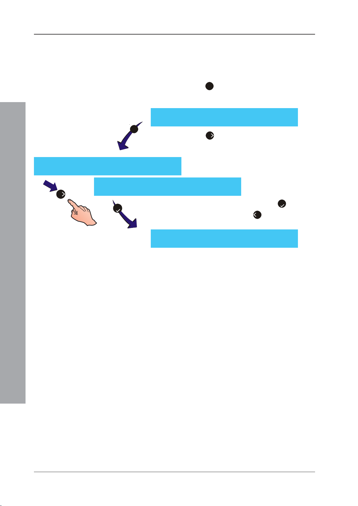
ID50 Series Panel - Installation, Commissioning & Configuration Manual
5.7.7 Two Zone
The Two Zone option has two states, Yes (Y) and No
(N). This option is available with the Fire, Pre-Alarm and
Plant Warning rules. To change the Two Zone rule setting:
1 Press the ‘7’ button (using the numeric keypad) to
CBE Rule:01 6:Class Change 7:Two Zone
7
2 Press the ‘6’ button to select the required setting.
CBE Rule:01 Two Zone = [N]
>:Change :Accept < : Cancel
CBE Rule:01 Two Zone = [Y]
6
>:Change :Accept < : Cancel
5
3 Confirm the selection by pressing the ‘5’ button. To
select the pattern Two Zone option from the menu
below.
9:Zones ¦ : More
Refer to Section 5.7, Control-By-Event Output
Rules for further information.
cancel the selection, press ‘4’. In either case the
menu below is re-displayed.
CBE Rule:01 6:Class Change 7:Two Zone
Configuration Mode
9:Zones ¦ : More
January 2010
88997-263-000-11, Issue 11
Page 93
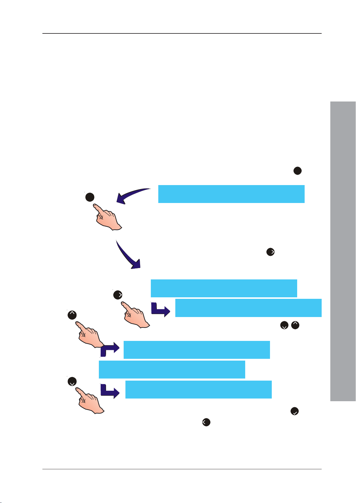
ID50 Series Panel - Installation, Commissioning & Configuration Manual
5.7.8 Zones
The Zones option determines the output response when
a zone detects an alarm. Each zone can be configured
as Yes (Y), No (N), Pulse (P), Coincidence (C) or Delay
(D) - see Section 5.7 for definitions of these parameters.
If Day Mode is enabled (Section 5.5.5.1, Day Mode
Activity) delays do NOT occur unless manually
activated. Manual activation can occur at any time of
day - it does not have to be during the set Day Mode
period. Delays are automatically de-activated with the
end of the day mode period.
To change the CBE Rules: Zone Setting from the CBE
Rules: Output menu, follow the described procedure
below:
1 From the menu options below, press the ‘9’ button
to select the Zones option.
CBE Rule:01 6:Class Change 7:Two Zone
9
9:Zones ¦ : More
2 The LCD displays the pattern number and zone range
x5
CBE Rule 01 Zones 1--------------------16
6
8
CBE Rule 01 Zones 1--------------------16
[Zone 06] [Yes ] YYYYNYYYNDDNCCNN
CBE Rule 01 Zones 1--------------------16
[Zone 06] [No ] YYYYNNYYNDDNCCNN
2
CBE Rule 01 Zones 1--------------------16
[Zone 06] [Pulse ] YYYYNPYYNDDNCCNN
[Zone 01] [Yes ] YYYYNYYYNDDNCCNN
(either 1 to 16 for fire alarms or 17 to 32 for plant
alarms) on line 1. Line 2 of the LCD displays the
selected zone’s number, the full description of its
current status and the zone’s flashing editable status.
To select a zone, press the ‘6’ button until the
appropriate zone number appears on line 2 in the
left-hand corner. The display cycles from 16 to 1 and
32 to 17.
CBE Rule 01 Zones 1--------------------16
[Zone 06] [No ] YYYYNNYYNDDNCCNN
Configuration Mode
3 To change a zone’s status, press the ‘2/8’ buttons
until the required state is displayed.
4 Confirm the changes by pressing the ‘5’ button.
Press ‘4’ to cancel any changes.
89 997-263-000-11, Issue 11
January 2010
Page 94
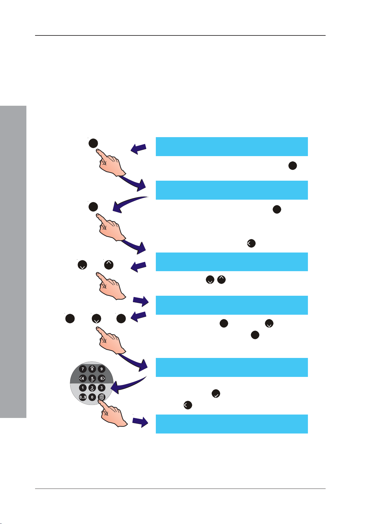
ID50 Series Panel - Installation, Commissioning & Configuration Manual
5.7.9 Device Inputs
The Device Inputs option is only available if the Device
Inputs CBE Rule is selected. This option determines the
output response to up to three (3) specified input devices
(modules or sensors). An input from any of the specified
devices will turn on the associated outputs.
To select the input devices:
1 Follow the procedures in Section 5.7.1, CBE Rules:
Output Type to change the CBE Rule type to Inputs.
The LCD displays the following menu:
CBE nn [INPUTS ] Dv1 Dv2 Dv3
1 : Change [EvSl ] --- --- ---
CBE Rule: nn 1:Type 2:Evac 4:Silence
CBE Rule nn Device 1: --1:Sensor 2:Module 3:Remove <: Exit
CBE Rule nn Device n: Snn
1:Sensor 2:Module 3:Remove <: Exit
or
1
0
2
or
8
2
or
31
Configuration Mode
2 Using the numeric keypad press the ‘1’ button to
display the following menu:
6:Class Change 10:Devices
3 At the numeric keypad press the ‘0’ button to select
the ‘Devices’ option. The LCD then prompts for a
device type selection (sensor or module) or the
removal of a device that has already been entered.
Alternatively press the ‘4’ button to exit this menu.
4 Use the ‘2/8’ buttons to select one of the 3 Device
Inputs to be edited.
5 Select either ‘1’ (sensor) or ‘2’ (module) to select
device address entry, or ‘3’ to remove the currently
selected device. If a device is to be entered, the
following (example is for a sensor) is displayed:
January 2010
CBE Rule nn Device n: --Enter sensor address <: Cancel
6 At the numeric keypad, enter the device address and
press the ‘5’ button to confirm. Alternatively press
‘4’ repeatedly to cancel the address entry.
CBE Rule nn Device n: Snn
1:Sensor 2:Module 3:Remove <: Exit
90997-263-000-11, Issue 11
Page 95
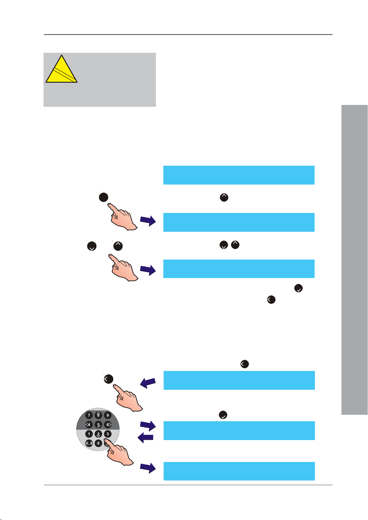
ID50 Series Panel - Installation, Commissioning & Configuration Manual
EN
12094-1
!
5.7.10 Soak Timer
CAUTION:
This product is not compliant
EN
12094-1
!
with EN 12094-1.
Fire extinguishing installations in
Europe are required to be certified as
compliant to this standard.
1
The Soak Timer allows the extinguishing output to be
activated for a specified time. If enabled, the
extinguishing output is activated for the period specified
by the Ext. System Soak Timer panel Setup option (see
Section 5.5.3.2 Extinguishing System Soak); if
disabled, the CBE rule activates associated outputs until
the panel is reset.
This option also affects the operation of device type MRL.
If enabled, associated MRL inputs will start the CBE Rule
extinguishing system delay (Section 5.5.3.1); if disabled,
the MRL inputs will start the CBE Rule immediately (for
Fire rules, will start the day mode delay, if active).
To enable/disable the Soak Timer:
CBE Rule: nn 1:Type 2:Filter
8:Soak Timer 9:Zones
1 Press the ‘8’ button (using the numeric keypad) to
select the Soak Timer option from the menu below.
CBE Rule:nn Soak Timer Enable = [N]
> : Change : Accept < : Cancel
2
or
8
2 Press the ‘2/8’ buttons to selectY(es) or N(o) for
Soak Timer Enable.
CBE Rule:nn Soak Timer Enable = [Y]
> : Change : Accept < : Cancel
3 Confirm the selection by pressing the ‘5’ button. To
cancel the selection, press ‘4’ button.
5.8 Zone Texts
The Zone Texts menu enables the editing or viewing of
text associated to a selected zone. To view or edit any
zone text descriptions, proceed as follows:
1 At the main Commissioning menu, using the numeric
keypad press the ‘4’ button.
4
[S1 COMM] 1 : Setup 2 : Circuit
3 : CBE Rules 4 : Zones 5 : Access ¦ : More
2 The Zone Text menu is displayed. Enter the zone
number required using the numeric keypad, then
press the ‘5’ button to select the zone.
Configuration Mode
[Zone Text] Select Zone No __
3 The LCD then displays the existing 20-characters of
text assigned to the zone on the upper line.
[<blank/existing text >] ¦ : Char : Done
>:Next <:Previous u1:Delete u3:Insert
91 997-263-000-11, Issue 11
January 2010
Page 96
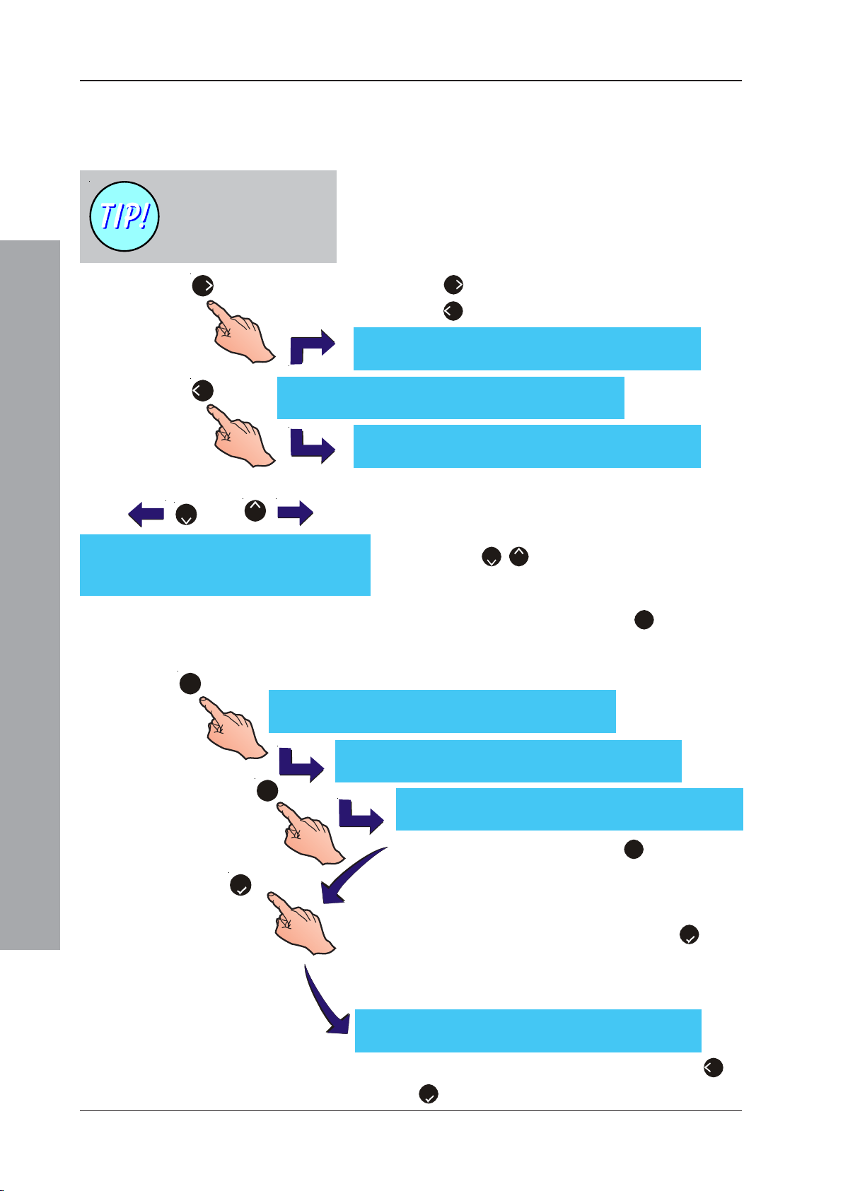
ID50 Series Panel - Installation, Commissioning & Configuration Manual
Text Editing
Note: The following also applies when editing device and
system text.
A position on the LCD with
a flashing underline
indicates that a Space text
character has been entered.
6
4
[blank/existing text ] ¦ : Char : Done
>:Next <:Previous u1:Delete u3:Insert
a.
2
8
_ABCDEFGHIJKLMNOPQRSTUVWXYZ
abcdefghijklmnopqrstuvwxyz0123456789
“`‘,.!?:;%=+-*/#$&@^_|()<>[]{}
The upper line of the LCD editable text menu displays
an area of twenty (20) characters. A flashing cursor on
the LCD indicates the currently-editable position. To enter
or edit existing text, proceed as follows.
1 To move the cursor within the editable area, press
the ‘6’ pushbutton to move it to the right or press
the ‘4’ pushbutton to move it to the left.
[blank/existing text _] ¦ : Char : Done
>:Next <:Previous u1:Delete u3:Insert
[blank/existing text_ ] ¦ : Char : Done
>:Next <:Previous u1:Delete u3:Insert
2 With the flashing character selected/cursor placed in
the desired position, press the appropriate buttons to
perform one of the following actions:
a. Use the ‘2/8’ buttons to scroll through the
alphabet in the order indicated at left.
b.
1
[blank/existing text ] ¦ : Char : Done
>:Next <:Previous u1:Delete u3:Insert
Configuration Mode
[blank/xisting text ] ¦ : Char : Done
>:Next <:Previous u1:Delete u3:Insert
3
c.
5
[Zone Text] Select Zone No __
b. Using the numeric keypad, press ‘1’ to delete the
flashing character. All text to the right of the deleted
character will move one space left and a blank
character will be inserted at the end of the line.
[blank/_xisting text ] ¦ : Char : Done
>:Next <:Previous u1:Delete u3:Insert
c. Using the numeric keypad, press ‘3’ to add a space
at the current position. All text to the right of the inserted
space will move one position right. If the text string now
exceeds 20 characters, the last character will be deleted.
3 When the text editing is completed, press the ‘5’ button
to confirm. The LCD returns to the Zone Text menu.
Note: The LCD will only register a maximum of 20
characters.
January 2010
4 Select another zone for text editing or press the ‘4’ or
‘5’ button to return to the main Commissioning menu.
92997-263-000-11, Issue 11
Page 97
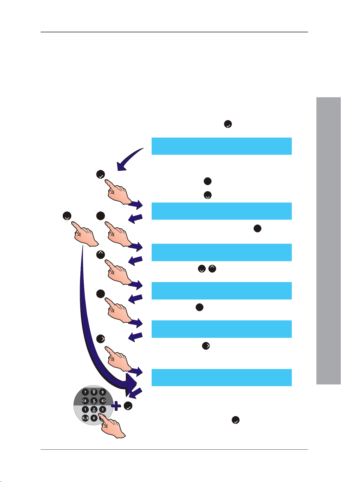
ID50 Series Panel - Installation, Commissioning & Configuration Manual
5.9 Access Options
The Access options menu allows the configuration of
the following access passcodes:
a. Up to ten (10) User passcodes.
b. One Commissioning engineer passcode.
The Access option is available from the Commissioning
menu. To configure access passcodes:
1 At the Commissioning menu, using the numeric
keypad press the ‘5’ button to display the Access
options menu.
[S1 COMM] 1 : Setup 2 : Circuit
3 : CBE Rules 4 : Zones 5 : Access ¦ : More
2 Use the numeric keypad to select the appropriate
5
option:
a. Press the ‘1’ button to select the User option.
b. Press the ‘2’ button to select the Engineer option.
[S1 Access] 1 : User 2 : Engineer
or
2
1
3 Selecting the User option (‘1’ on the numeric
keypad) displays the following menu:
[S1 Access] Passcode 0 = nnnn
8
1
6
>:Change 1:Delete ¦ : More <:Cancel
i Use the ‘2/8’ buttons to select a user access code
number (range 0 to 9).
[S1 Access] Passcode 3 = nnnn
>:Change 1:Delete ¦ : More <:Cancel
ii Press ‘1’ on the numeric keypad to delete the
currently displayed access code and disable that user.
[S1 Access] Passcode 3 = ________
>:Change 1:Delete ¦ : More <:Cancel
iii Press the ‘6’ to display the change menu, see below.
4 The change menu prompts for entry of a new access
code:
[Setup] Passcode 0 = nnnn
Enter new value ____ : Confirm <:Cancel
Configuration Mode
Note: If the Engineer option is selected the access code
5
number is replaced by (ENG).
5 Using the numeric keypad, enter a new four (4) digit
passcode and press ‘5’ to confirm. After editing a
‘User’ passcode the display automatically returns to
the User passcode selection menu. The ‘Engineer’
passcode returns to the Access menu.
93 997-263-000-11, Issue 11
January 2010
Page 98
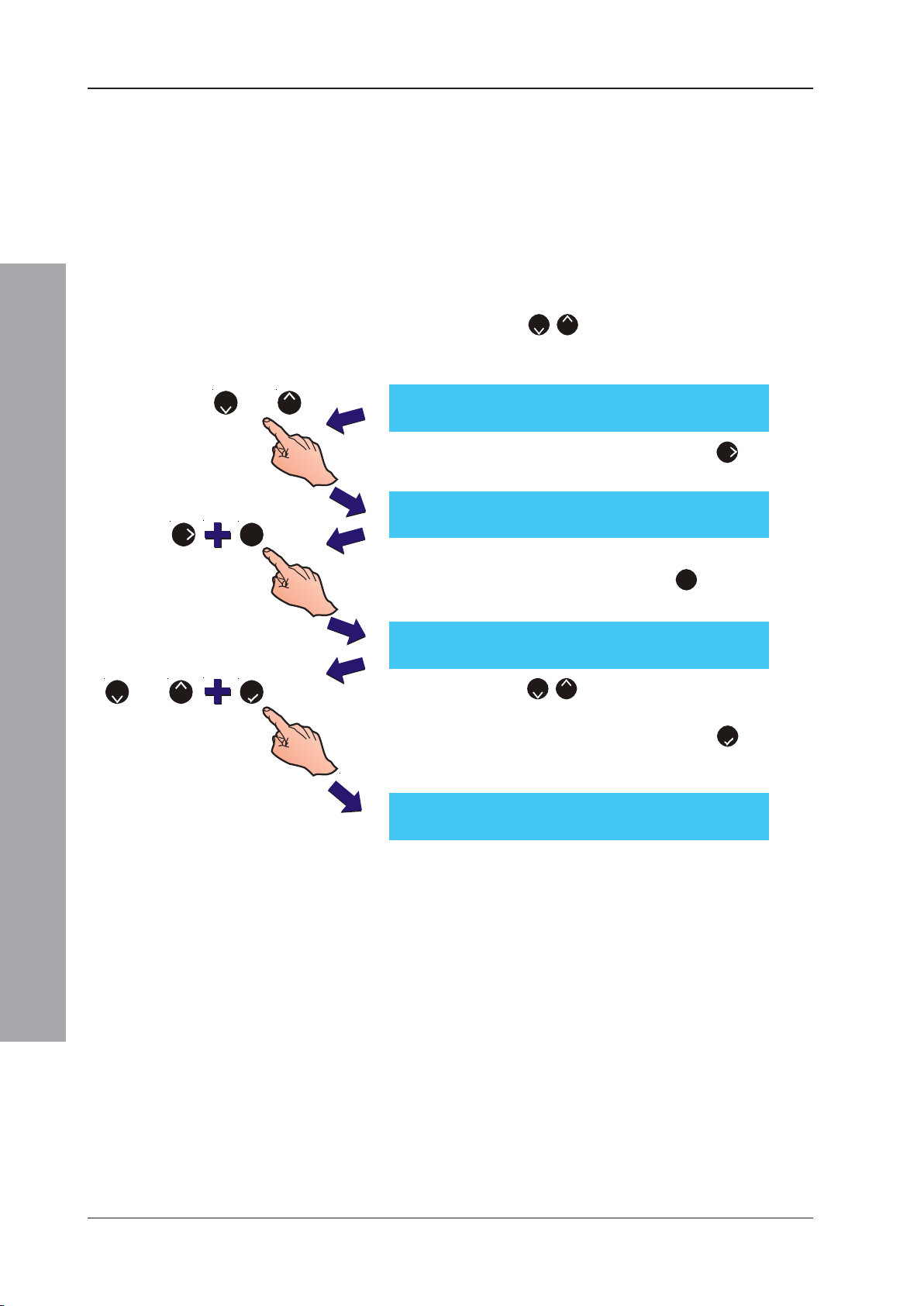
ID50 Series Panel - Installation, Commissioning & Configuration Manual
5.10 System Options
The System menu allows:
a. The crystal frequency to be set.
b. The existing panel configuration to be cleared.
5.10.1 Crystal Frequency
To adjust the Crystal Frequency:
1 Press the ‘2/8’ keys to display additional options
(6 : System, 7 : Normal and ¦ : More) from the main
Commissioning menu.
or
82
16
or
2
8
5
Configuration Mode
[S1 COMM] 1 : Setup 2 : Circuit
[S1 COMM] 6 : System 7 : Normal
[S1 SYSTEM] 1 : Crystal 2 : Wipe Memory
Crystal Frequency = nn.nnnnn MHz
: Update ¦ : Change < : Cancel
3 : CBE Rules 4 : Zones 5 : Access ¦ : More
2 On the numeric keypad, press the ‘6’ button to
display the System menu.
¦ : More
3 At the System menu select the required option. Using
the numeric keypad, press the ‘1’ button to select
the Crystal option.
4 Using the ‘2/8’ buttons, scroll through the Crystal
Frequency options until the displayed value matches
that written on the PCB. Press the ‘5’ button to
update/confirm the selection and return to the System
menu.
January 2010
94997-263-000-11, Issue 11
Page 99
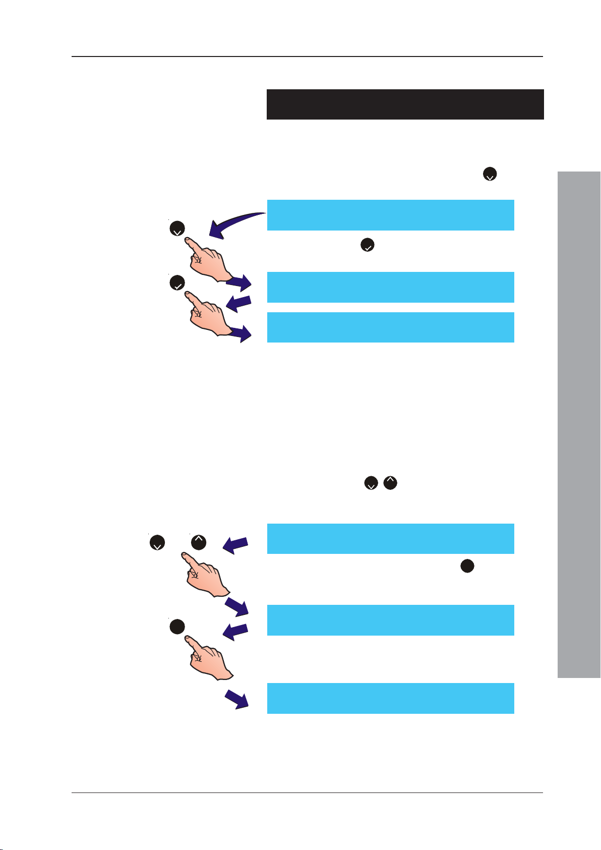
ID50 Series Panel - Installation, Commissioning & Configuration Manual
5.10.2 Wipe Memory
CAUTION: USE THIS OPTION WITH CARE! ALL
CONFIGURATION PARAMETERS WILL BE DELETED!
To wipe the panel’s memory, display the System menu
and proceed as follows:
1 Using the numeric keypad, press the ‘2’ button to
select the Wipe Memory option.
[S1 SYSTEM] 1 : Crystal 2 : Wipe Memory
2
2 Press the ‘5’ button to confirm the wipe memory
procedure. The LCD displays the following message.
or
5
Wipe ALL configuration memory
Press to confirm < : Cancel
Wiping configuration memory
Please wait . . .
When the configuration has been wiped the LCD redisplays the System menu.
5.11 Normal
The Normal function returns the display to the Level 2
Configuration menu in a normal supervisory mode.
To return to the Level 2 Configuration menu and retain
Level 3 access (Engineer):
1 Press the ‘2/8’ buttons to display additional
options (6 : System, 7 : Normal and ¦ : More) from
the Commissioning menu.
[S1 COMM] 1 : Setup 2 : Circuit
82
3 : CBE Rules 4 : Zones 5 : Access ¦ : More
2 Using the numeric keypad, press ‘7’. The panel will
reset and return to normal supervisory mode at the
User Menu.
Configuration Mode
[S1 COMM] 6 : System 7 : Normal
7
When ALL configuration procedures have been
completed, remember to fit the Configuration
Lock jumper Link (J9).
[S1] 1:Test 2:Disable/Enable 3:Clock
4:View Mode 5:Commission
95 997-263-000-11, Issue 11
¦ : More
January 2010
Page 100

ID50 Series Panel - Installation, Commissioning & Configuration Manual
Appendix 1 - Specification
ID50 Series Panel
General:
This fire control panel is designed to comply with the
requirements of EN 54 Part 2/4. See Section 1.4 CE Marking
for further details. In addition to the basic requirements of
EN 54-2, the panel may be configured to conform with optional
requirements as described in Section 1.5 EN 54 Functions.
Mechanical:
Construction: Sheet steel enclosure carries all
displays and controls under a steel
sheet cover.
Dimensions (mm): 365(h) x 380(w) x 110(d)
Approx Weight
Back Box: 6kg (no batteries)
Environmental:
Climatic classification: 3K5, (IEC 721-2-3)
Operating temperature: -5oC to +45oC,
(recommended +5oC to 35oC)
Humidity: 5% to 95% R.H.
Height above sea level: Maximum, 2000m
Panel sealing: IP 30, (EN 60529)
Vibration: EN 60068-2-6, 10-150Hz at
0.981ms-2 (Meets the requirements
of EN 54-2/4)
EMC: Emissions: EN 61000-6-3
Immunity: EN 50130-4
Safety: EN 60950
Displays and Indications:
Alphanumeric display: 2 line x 40 character, backlit LCD.
LED Status Indicators: FIRE, DISABLEMENT, TEST,
FAULT, DELAYS ACTIVE, FIRE
OUTPUT: FAULT/DISABLED, FIRE
OUTPUT ACTIVE, PLANT ALARM,
POWER, FAULT, POWER SUPPLY
FAULT, EARTH FAULT, SYSTEM
FAULT, SOUNDER: FAULT/
DISABLED, PRE-ALARM, FIRE
CONTROL O/P: FAULT/DISABLED.
Appendix 1 - Specifications
Zone Indicators: Individual FIRE and Fault/Disable/
Test indicators for 16 zones.
A1 - 1 997-263-000-11, Issue 11
January 2010
 Loading...