

Page 1
INSTRUCTION MANUAL
COLOR VANDAL PROOF CAMERA
HVD-735NT/PT
HVD-735NW/PW
HVD-505N/P
About this manaul
Before installing and using the camera, please read this manual
carefully. Be sure to keep it handy for later reference.
This instruction manual covers for use in the following models. Any
difference among the those models is indicated when necessary.
PRECAUTIONS
■ Do not open or modify
Do not open the cabinet exet during maintenance and
installation, as it may be dangerous and cause damages.
■ Do not put objects inside the unit
Make sure that no metal objects or flammable substances
get insdie the camera. It could cause fire, short-circuits or
damages.
■ Be careful when handling the unit
To prevent damage, do not drop the camera or subject
it to strong shock or vibration.
■ Install away from electric or magnetic fields
■ Protect from humidity and dust
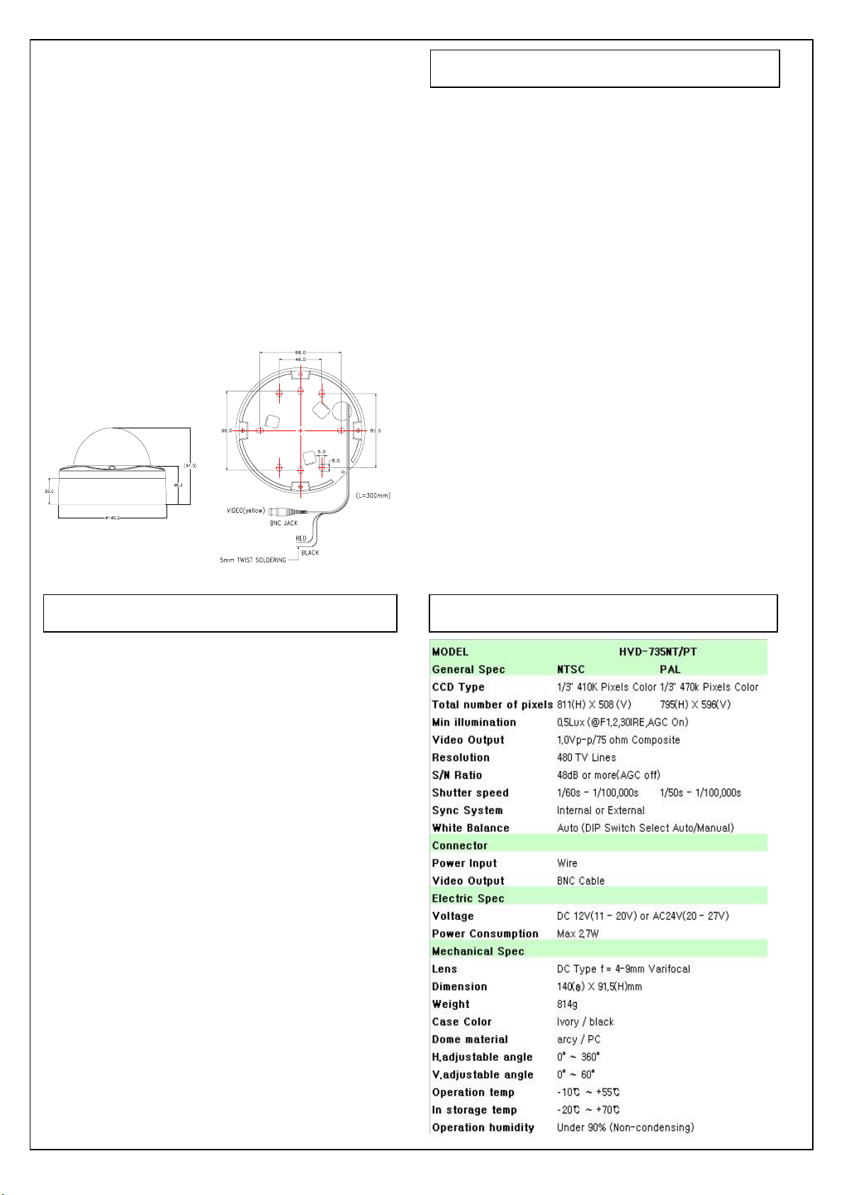
Dimensions : mm
Honeywell
DC12V or AC24V
TROUBLESHOOTING
Before sending the camera out for repair, check the items
below. If the problem persists after checking these items,
contact your service center.
■ If no image appears
Is the coaxial cable attached securely?
Are the power and voltage normal?
Has the iris of the lens inside the camera been
adjusted correctly (with the level volume) ?
Is there adequate illumination?
■ Protech from high temperature
Be careful when installing colose to the ceiling , in a
kitchen
or boiler room, as the temperature may raise to high
levels.
■ Cleaning
Dirt can be removed from the cabinet only by wiping it
with a soft cloth moistened with a soft detergent solution.
■ Mounting Surface
The mounting surface material must be strong enough
to secure the camera.
SPECIFICATION
■ If the image is unclear
Is the lens in focus?
Is the lens dirty?
Dirt of fingerprints on the lens can adversely affect the
images. Gently wipe any dirt or fingerprints off the lens
with a soft cloth or lens cleaning paper and cleaning
fluid (commercially available).
Is the monitor adjusted correctly?
WARNING:
TO PREVENT THE RIST OF FIRE OR ELECTRIC
SHOCK, DO NOT EXPOSE THIS APPLIANCE TO
RAIN OR MOISTURE.
Page 2

S
W
T
CONNECTIONS AND CAMERA SETTINGS
ON
■ CONNECTIONS ■ LENS ADJUSTMENT
DC12V
AC24V
Black (-)
Focus
Red (+)
60˚
60˚
Zoom
Focus
360˚
CAUTION
Check for polarity when using a DC 12V or AC 24V power supply.
1. Adjust the panning(360˚) and tilt(60˚) position.
2. Setting the zoom position by using Zoom Lever Screw.
3. Setting the focus by using Focus Lever Screw.
■ CAMERA SETTINGS for HVD-735NW/P
OFF
ON
■ CAMERA SETTINGS for HVD-505N/P & HVD-735NT/P
HVD-505N/P HVD-735NT/PT (Upper board & Rear board)
(10
(3)
(1)
(2)
OFF ON
1324
(7)
(7)
(6)
White balance
lock button
(1)
ON
162345 78
This switch is
not used.
(2)
(3)
360˚
(4)
(5)
(8) (9
ON
ON
OFF
12
OFF
ON
● Correcting Flicker (1)
Correct screen flickering athat occurs when positioned under
fluorescent lights that use a 50 Hz power supply frequency.
ON Under 50 Hz fluorescent lights
OFF Normal setting
● Confirming the iris setting (3)
ON The default setting when DC auto-iris lens is installed
OFF The default seeting when fixed iris lens is installed
CAUTION : The iris setting is preadjusted as the best condition for
use at time of factory shipment, so it isn't necessary to change settings
● Compensating for backlight (2) ● Setting gain control (AGC) (4) - HVD-735NT/PT
ON When back light is so bright For adjusting the sensitivity of the camera. Use this setting for shooting
OFF Normal setting
CAUTION : It will be correctly set by adjusting level volume 7.
in dark environments.
ON Normal setting
OFF Set this when there is excessive noise
Page 3

SPECIFICATION
INSTALLATION
E
D
C
G
A
1 Use the supplied hexagon wrench to remove the four
F
I
H
fixing screws (B) of dome cover (A).
2 Make screw holes and a cable hole in the supplied
cushioning sheet (D) that attaches to the back of the
camera unit (C) .
3 Attach the cushioning sheet (single-sided tape) to the
back of the camera unit.
4 Align the camera unit with the surface of the ceiling,
make marks on the ceiling in the places where the
screw holes are to be drilled, and then drill the four holes.
5 Cut a hole (diameter:73mm) in the ceiling for routing
the cables.
6 Pass the power cable (E) and video cable (F) from the
camera unit through the cable hole in the ceiling.
7 Align the four screw holes in the camera unit (C) with
the screw holes in the ceiling, and then secure the
camera in place by tightening the four or more screws
(G) throught the washers.
8 Carry out the settings and adjustments for the camera.
9 If the dome liner (H) is secured in place, loosen the
screw (I).
Adjust the dome liner (H) so that the dome camera's
lens is visible from the camera window, and then
use a philips screwdriver to fix the dome cover.
10 Secure the dome cover (A) by tightening the screws (B).
B
Page 4

● Setting white balance (5) - HVD-735NT/PT ● Adjusting gamma compensation (8)
Adjusts the balance of colors. Basically AUTO TRACKING - HVD-735NT/PT
WHITE BALANCE is default setting. When this function For adjusting the gamma compensation, use this setting
does not work properly, select other settings. to adjust the signal correction/contrast so that the image looks
Settings SW6 SW7 SW8
AUTO TRACKING
WHITE BALANCE
AUTO WHITE
BALANCE
MANUAL WHITE
BALANCE
WHITE BALANCE
LOCK
INDOOR SETTING
(LIGHT 1)
INDOOR SETTING
(LIGHT 2)
INDOOR SETTING
(LIGHT 3)
OUTDOOR
SETTING
OFF ON OFF
OFF OFF OFF
OFF OFF ON
ON
OFF
ON
ONOFF
OFF
ON OFF ON
ON
ON ON
ON OFF
ON
Normal setting
Automatically adjusts the
white balance when
objects are near
Fine-tune the white balance
manually. Adjust the color
using (6) button. (Left:Red,
Right:Blue). If an AC24V
adapter user sets MANUAL
WHITE BALANCE, sync
adjustment cannot be
performed. To perform sync
adjustment, do it with button
(6) before setting MANUAL
WHITE BALANCE.
Adjust the white balance when
the brightness is constant.
After setting the switch at left,
keep pressing the white
balance lock button and
release it to set it.
When the room is lit by fluorescent
or incandescent lights (3200 ˚K)
When the room is lit by
fluorescent lights (4200˚K)
When the room is lit by
fluorescent lights (4700˚K)
Set for outside light (6500˚K)
● Setting monitor synchronization (6) - HVD-735NT/PT
(AC 24V adaptor users)
Vertical sync disturbance may occur when a selector is used to
switch between multiple cameras connected to one monitor.
To prevent vertical sync disturbance, adjust (6).
CAUTION
* When using the DC 12V adaptor, sync setting is set to internal sync.
* If MANUAL WHITE BALANCE is set, sync adjustment cannot
be performed. Change to a different white balance setting.
Contents
natural.
ON
OFF Normal setting (gamma is set to 0.45)
Gamma is set to 0.6. Makes the gamma compensation
stronger than with the normal setting.
● Setting the electronic shutter speed (9),(1)(2)(3)
- HVD-735NT/PT
The electronic shutter speed can be adjusted after setting
"ON" for this setting(9)
Changes the switch settings for (1),(2) and (3)
ON
to change the electronic shutter speed.
At this time the actual Flickerless and Backlight
Compensation are ignored.
OFF
Normal Setting
When the electronic shutter mode is set to "ON", a
combination of the following three settings can be used to
set up to eight speed levels.
Shutter
speed
SW1
flickerless (1)
SW2
Backlight
compensation (2)
1/60 OFF ON OFF
1/100 ON ON OFF
1/250 OFF OFF OFF
1/500 ON OFF OFF
1/1000 OFF ON ON
1/2000 ON ON ON
1/4000 OFF OFF ON
1/10000 ON OFF ON
SW3
Iris setting (3)
● Setting Mirror Mode (10)
ON Mirror Function is working
OFF Mirror Function is not working
● Adjusting level volume (7)
If the entire image is too dark or bright, or the backlight compensation
is not correct even after (2) is set to "ON", you need to adjust the level
volume.
CCW (Low) Closes the lens iris, making the entire image darker
CW(High) Opens the lens iris, making the entire image drighter
Office : 18F, Kukje Center Building 191
Hanganro-2ga Yongsan-gu
Seoul 140-702, Korea
Phone : 82-2-799-6109
Fax : 82-2-749-6119
Http://www.honeywell.co.kr/cctv/english
 Loading...