

Page 1

Honeywell
HUS-NVR-1032-E
32CH Network Video Recorder
User Guide
Document 800-13326 Rev. A
Page 2

Page 3

Honeywell
Contents
1 About This Document .................................................................................................................... 1
Overview of Contents ....................................................................................................................... 1
Special Fonts and Symbols ............................................................................................................. 1
How to Use This Document ............................................................................................................. 1
2 Introduction .................................................................................................................................... 3
Features ........................................................................................................................................... 3
Specifications ................................................................................................................................... 4
Unpack Everything ........................................................................................................................... 5
Operating Keys ................................................................................................................................ 6
Front View .................................................................................................................................. 6
Rear View .................................................................................................................................. 7
3 Installation and Connections ........................................................................................................ 9
HDD Installation ............................................................................................................................... 9
Video and Audio Input/Output ........................................................................................................ 10
Video Input............................................................................................................................... 10
Video Output ............................................................................................................................ 10
Audio Output ............................................................................................................................ 10
Intercom Input (Reserved) ....................................................................................................... 10
Intercom Output (Reserved) .................................................................................................... 10
Alarm Input/Output ......................................................................................................................... 11
Specifications of Alarm Input ................................................................................................... 11
Specifications of Alarm Outputs .............................................................................................. 11
Specifications of Alarm Output Relay ...................................................................................... 12
Example of Alarm Input/Output Connection ............................................................................ 12
Network Connection ....................................................................................................................... 12
USB Connection ............................................................................................................................. 13
e-SATA ........................................................................................................................................... 13
4 Basic Operations .......................................................................................................................... 14
Using the Mouse ............................................................................................................................ 14
Turning On ..................................................................................................................................... 15
Default Accounts ............................................................................................................................ 16
Wizard ............................................................................................................................................ 17
Switch User .................................................................................................................................... 22
Change Password .......................................................................................................................... 23
Log Off............................................................................................................................................ 23
Restart ............................................................................................................................................ 24
Shutdown ....................................................................................................................................... 24
Recovery (Power Failure) .............................................................................................................. 25
Replacing the Button Cell Battery .................................................................................................. 25
5 System Operation and Configuration ........................................................................................ 26
i
Page 4

Honeywell
Live ................................................................................................................................................. 26
Video Window Operation ......................................................................................................... 28
Views Settings ......................................................................................................................... 28
Device Operation ..................................................................................................................... 30
Storage .................................................................................................................................... 37
PTZ Control ............................................................................................................................. 40
Patrol ....................................................................................................................................... 42
Playback ......................................................................................................................................... 44
Video Window Operation ......................................................................................................... 45
Search and Back Up ...................................................................................................................... 47
Filter ......................................................................................................................................... 47
Search Videos ......................................................................................................................... 47
Back Up Videos ....................................................................................................................... 49
View Log ........................................................................................................................................ 50
Operation Log .......................................................................................................................... 50
Alarm Log ................................................................................................................................ 51
System Status ................................................................................................................................ 55
Basic Status ............................................................................................................................. 55
Network Status ........................................................................................................................ 55
Hard Disk Status ...................................................................................................................... 57
Record Setup ................................................................................................................................. 58
Scenario Mode (Scheduled Recording) .................................................................................. 58
Trigger Profiles (Alarm Recording) .......................................................................................... 59
System Setup ................................................................................................................................. 61
General Settings ...................................................................................................................... 61
System Settings ....................................................................................................................... 62
Display Settings ....................................................................................................................... 65
User Settings ........................................................................................................................... 66
Network Settings ..................................................................................................................... 69
Alarm Settings ......................................................................................................................... 70
6 NVR Internet Explorer (IE) Client ................................................................................................ 72
System Requirements .................................................................................................................... 72
Internet Explorer Configuration ...................................................................................................... 72
Login............................................................................................................................................... 75
Playing Live Video .......................................................................................................................... 76
Local Record .................................................................................................................................. 77
Local Playback ............................................................................................................................... 78
ii
Page 5

Important Safety Instructions
Honeywell
Before operating or installing the unit, read and follow all instructions. After
installation, retain the safety and operating instructions for future reference.
1. Electrical safety
All installation and operation here should conform to local electrical safety codes.
We assume no liability or responsibility for fires or electrical shock caused by improper
handling or installation.
2. Transportation
Heavy pressure, violent vibration and water must be avoided during transportation, storage
and installation.
3. Install and operate the device in a proper environment
Do not install the unit in an extremely hot or humid location, or in a place subject to direct
sunlight, dust or mechanical vibration.
The unit is not designed to be waterproof. Do not expose it to rain or water.
Situate away from items that produce heat or are heat sources. Keep the unit well-ventilated.
Place the unit on a stable flat surface or install it on the rack.
Do not place any objects on the unit.
4. Battery
The built-in battery life is approximately 2 years as an indication of replacement. (This is just
an indication of replacement. We are not providing any guarantee for the built-in battery
lifetime. Replacement costs of the built-in battery are not covered by the warranty even if it
needs to be done within the warranty period.) The battery of the same type must be used to
replace the old one to avoid explosive danger. Ask the supplier where the unit was
purchased when replacement of the battery is required.
5. Rating plate and user guide
Refer to the rating plate placed on the rear panel of the unit for the information on equipment
classification and power source, etc.
Read and follow all instructions in the user guide when installing and operating the unit.
v
Page 6

Page 7

1 About This Document
Indicates referenced chapter, figure number, page number, etc. In the
Alerts the user to the presence of important operating and maintenance
Thank you for purchasing the HUS-NVR-1032-E (32 Channel Network Video Recorder)
NVR.
This user guide describes the features, installation, configuration and operation of the HUSNVR-1032-E, hereinafter referred to as “NVR”.
Overview of Contents
This user guide includes:
Chapter 1, About This Document, a brief introduction of this user guide.
Chapter 2, Introduction, provides the features, specifications and shipping list of this product.
Chapter 3, Installation and Connections, describes how to install and connect the unit.
Chapter 4, Basic Operations, describes the basic configurations and common operations in
the system.
Chapter 5, System Operation and Configuration, provides comprehensive and detailed
instruction on the system operations.
Chapter 6, NVR Internet Explorer (IE) Client, introduces how to configure the Internet
Explorer and login NVR IE Client.
Honeywell
Special Fonts and Symbols
Italic
Bold
electronic version, click it to go to the corresponding page.
Indicates a button.
(servicing) instructions in the literature accompanying the product.
How to Use This Document
• Pictures in this manual are for reference only, please see the actual items for details.
• This product is subject to updates or changes without prior notice.
1
Page 8

About This Document
• Please familiarize yourself with this manual before operation and ensure its accessibility
for future use.
• The manual has been reviewed and its accuracy is guaranteed. If there is any
uncertainty or controversy, please refer to the final explanation of Honeywell. Honeywell
does not take any responsibility for any consequences caused by the misunderstanding
of the manual or incorrect operations by the user.
2
Page 9

2 Introduction
This chapter provides the features and specifications of the NVR and introduces its front and
rear panel keys.
Features
Real-time Surveillance
• Supports real-time video on monitors via BNC, VGA and HDMI ports.
• Supports 16 channels (D1) / 8 channels (720P) / 4 channels (1080P) video signal and
one channel audio signal decoded simultaneously.
Honeywell
• Supports 32 channels video input (64Mbps).
• Supports various window layout options.
• Supports displaying information of recording types and video events.
• Supports checking system logs on local machine or IE client.
Record and Playback
• Supports various recording modes – manual recording, scheduled recording, panic
recording and alarm recording. Prerecord is available on all video modes.
• Supports playback on local machine or IE client.
• Supports synchronous or independent playback of 4 channels (1080P) videos.
• Supports search and play history videos based on search conditions.
• Supports multiple operations at the same time—recording, playback, search and back
up.
• Supports various playback speeds and playback frame by frame.
• Supports displaying the date and time of video during playback.
Alarm
• Supports 16-channel external alarm inputs. External alarm detecting devices include
smoke sensors, infrared sensors, temperature sensors, etc.
• Supports system alarm including: hard disk status, system temperature, IP address
conflict, etc.
• Supports network alarm including: motion detection, video loss, on line, off line, etc.
• Supports 4 relays alarm output.
• Supports alarm linkage: recording, PTZ control and audible alarm.
PTZ Control
• Supports controlling PTZ via the network.
3
Page 10

Introduction
Video Storage
• 8 SATA HDD slots supporting hot plug.
• 2 e-SATA ports to connect e-SATA disk or specified disk array (recomended).
• Options on full HDD – Overwrite or Stop recording.
• Video recordings are stored in specialized formats to prevent the data from being
altered and guarantee its integrity.
Video Backup
• Use USB devices via the USB 2.0 interface.
• Download history videos from NVR through the network interface.
Network Operations
• Remote real-time surveillance.
• PTZ control
• Play back, search and download history videos.
• Configure system settings and upgrade the firmware from the web client.
• Handle alarms and view system log remotely.
• User and password management can prevent unauthorized users from logging into
the system.
Communication Ports
User Interface Operations
Specifications
Refer to the following table for the specifications:
Table 2-1 Specifications
Parameter Value
Operating System Embedded LINUX
User Interface GUI (supports mouse operations)
Network Bandwidth 64Mbps
• RS485 port (Reserved)
• RS232 port
• Alarm input and Alarm output
• RJ45 Ethernet port
• With the mouse
• With the keys on the front panel of NVR.
• UI language supports English, simplified Chinese and traditional Chinese.
4
Page 11

Honeywell
1 CVBS output, use BNC port (1.0V
resolution: D1(4CIF), NTSC 704 * 480, PAL 704 * 576
Video Output
Intercom Input/Output Reserved
Audio Output 1 channel, RCA.
Audio Compression G.711
Video Recording
HDD
Alarm Input
Alarm Output
Network Interface 2 RJ-45 ports (10/100/1000M)
Backup
1 VGA output; resolution: 1280*1024/1920*1080
1 HDMI output; resolution: 1280*1024/1920*1080
1080P/720P/D1/4CIF/2CIF/CIF/QCIF 1~25 fps/PAL;
1~30fps/NTSC
Dual encoding stream
8 SATA ports, 2 e-SATA ports
16 channels, 0V~5.0V.
4 channels, 30VDC 1A Normal Open/Normal Close Form-C
relay
USB Device/Network download
, 75 Ω);
p-p
Power Supply 100~240 VAC 50~60Hz
Power Consumption
(without HDD)
Operating Temperature
Storage Temperature
Humidity 20%~80%
Dimensions 482mm (W ) x 478mm (L) x 91mm (H)
Weight
Mounting Desktop or rack
Unpack Everything
Before unpacking NVR, make sure that there is no visible damage on the box.
Unpack the box, and check the accessories according to the ACCESSORY LIST below.
Table 2-2 Accessory List
Item Quantity
<50W
-10℃~55℃
-40℃~70℃
Gross weight: 11.5 kg
Net weight: 9.3 kg
HUS-NVR-1032-E (32 channels
network video recorder)
1
5
Page 12

Introduction
CD 1
Power cord 3
GIGA LAN CABLE, 3000mm, CAT-5E 1
Accessories box
Desiccant (SILICA)
Remove the protective film on the NVR after the above procedures.
Operating Keys
Front View
Figure 2-1 Front View
6#-32 * 1/4 FM 32
M6*12 PB 2
Quality certification 1
Terminal Blocks 4
Quick Guide 1
1
Table 2-3 Name and Description of Keys (Front View)
No. Symbol Name Function
1
2
3 STATUS
6
Hold it down for over 5 seconds to turn on
ON/OFF Switch
Panic Recording
Key
System Status
Indicator
the NVR.
When NVR is turned on, hold the button
down over 5 seconds to turn NVR off.
Hold it down for over 1 second to start/stop
the panic recording.
After pressing the “ON/OFF Switch”, the
blue (Off) – the system is starting;
Blue (On) – the system is running properly;
Red (Flashing) – system exception.
Page 13

Honeywell
4 ALARM Alarm Indicator Flashes when an alarm occurs.
5 REC Recording Indicator On – NVR is recording.
6 LAN1 Network 1 Indicator Flashes when LAN1 is connected.
Rear View
7
LAN2
8
9
10
11
Figure 2-2 Rear View
Network 2 Indicator Flashes when LAN2 is connected.
HDD Tray Button Press to open the HDD tray.
HDD Active Indicator Flashes when HDD is active.
HDD Connection
Indicator
USB Port
Indicates HDD connection status. On when
HDD is powered.
2 USB 2.0 ports for connecting USB
devices.
Table 2-4 Name and Description of Keys (Front View)
No. Name Description
1 Power Switch Turn power on/off.
2 Power Inlet 100~240 VAC 50~60Hz
3 BNC Output
4 AUDIO Output Real-time or playback audio output
5 Intercom Output Intercom audio output (Reserved)
6 Intercom Input Intercom audio input (Reserved)
7 ALARM In 16 alarm-in ports
8 ALARM Out 4 alarm-out ports (SPDT Relay)
BNC (PAL/NTSC (1.0V
output
, 75 Ω)) port, auxiliary video
P-P
7
Page 14

Introduction
+12V DC +12V output, 500mA
RS485 (Reserved)
9 USB Port USB 2.0, for connecting USB devices.
10 LAN1, LAN2 Network connection
11 VGA Port Main video output/User interface
12 RS232 Port Serial port
13 HDMI Port Main video and audio output/User interface
14 e-SATA Port
15 Grounding Screw For grounding
16, 17 Labels MAC address and rating plate
Storage Expansion by connecting storage devices
with this port
8
Page 15

3 Installation and Connections
This chapter explains how to install the HDD and connect the NVR to related devices.
• Attempting to open or disassemble the unit may expose you to
dangerous voltage or other hazards and damage the unit.
• Make sure to ground the cabinet of the NVR! The grounding screw is
HDD Installation
on the rear panel of the unit.
Honeywell
It is recommended that you use SATA-II HDDs (500G and above).
Consult the vendor to get the latest compatible hard disk list.
1. Pull out the HDD tray from the NVR.
2. Secure the HDD in the tray with the screws
provided in the package.
9
Page 16

Installation and Connections
3. Inset the HDD tray into the NVR.
Video and Audio Input/Output
Video Input
The bandwidth for this NVR is 64Mbps; you can check the network information on the
“System Status” screen. See “System Status” section on page 55.
It is recommended that you connect an IP camera to only one NVR,
otherwise there might be management problems.
4. Push the handle until it clicks into the lock.
Video Output
The BNC (PAL/NTSC (1.0VP-P, 75 Ω)) port, VGA port and HDMI port are dedicated for video
output. The BNC port is the “MON” auxiliary output port on the rear panel.
HDMI port can be used for simultaneous transmission of video and audio, which can be
either the live audio of one channel or playback audio. If using a HDMI port, a certified HDMI
cable should be used.
It is recommended that you use a 16:9 industrial monitor (supports 1080p) equipped with
HDMI or VGA port as the output device of the NVR.
Audio Output
The audio signal is 3000mVp-p 5K Ω (RCA) and can be sent to earphones with low
impedance, active speakers, or other audio devices. “Audio out 1” is for audio output.
Intercom Input (Reserved)
Connect intercom input through “Mic In” port (No.6 in Figure 2-2). The input range is 2Vp-p.
Intercom Output (Reserved)
Common line intercom between NVR and remote intercom device through the network are
supported. The audio codec only supports G.711 (Sampling rate: 8K) standard. Remote
intercom devices can be connected to the NVR directly or by network switching devices
through LAN1/LAN2 on the rear panel of the NVR.
10
Page 17

“MIC In” on the rear panel of NVR is for local audio input of the intercom system; “Audio out
2” is for local audio output. Proper settings to Intercom audio enable using active and
passive microphones. Earphones and active loudspeakers can be connected to the intercom
output interface.
Alarm Input/Output
Refer to the following figure for alarm input/output interfaces.
Figure 3-1 Alarm Input/Output
Table 3-1 Alarm Input/Output
Honeywell
Name Description
GND For grounding
+12V
ALARM IN 1-16 16 channels alarm input
ALARM OUT1-4
RS485 A/B RS485 communication port (Reserved)
Specifications of Alarm Input
1. The 16 alarm inputs can be set to normally open or normally closed independently.
2. The “COM” ports of alarm detectors should connect to the GND of NVR.
3. The power for alarm detectors can be provided by NVR (+12V power) or other external
power supplies.
Specifications of Alarm Outputs
1. Four alarm outputs (normally open or normally close); external alarm devices should be
powered independently.
2. Refer to the specifications of the relay which are listed in the following table in order to
avoid overloading.
Power output for external alarm devices
Max. current: 500mA
4 channels alarm output. “NC” is the normal close port; “NO” is
the normal open port; “COM” is the common port.
11
Page 18

Installation and Connections
Specifications of Alarm Output Relay
Table 3-2 Alarm Output Relay
Model: HFD3
Rated switch capacity 2A 30VDC, 0.5A 125VAC
Rating (Resistance
load)
Open delay <4ms
Close delay <4ms
Max switch power 62.5VA 60W
Max switch voltage 250VAC, 220VDC
Max switch current 2A
Example of Alarm Input/Output Connection
This example is only for your reference. Refer to the specifications of your
own devices.
Refer to the following figure for the connections of electronic lock, alarm indicator and PIR.
Figure 3-2 Example – Alarm Input/Output Connection
Network Connection
The standard RJ45 port makes it convenient to connect the NVR to the network. LAN1 and
LAN2 are for connecting to other network devices.
The NVR network is a self-adapting 10/100/1000Mb. Use the provided network cable for
connection with network devices or CAT-5E STP. When establishing a network, it is
recommended to use a network switch or router, but not a hub.
12
Page 19

USB Connection
There are two USB ports (5V 500mA) on the front panel and one on the rear panel for
connecting USB devices. To ensure the NVR runs properly, do not connect USB devices
which consume a lot of power.
e-SATA
e-SATA port is used for connecting SATA disk or specified disk arrays (contact the technical
support for the model number of HDD array).
Honeywell
Make sure that the initialization of disk (RAID ARRAY) has been completed
successfully before use. Refer to the manual of the disk (RAID ARRAY).
13
Page 20

Basic Operations
4 Basic Operations
This chapter provides basic configuration and operation information of NVR.
Using the Mouse
Make sure that HDDs have been installed and all the cables are
connected properly before turning on the NVR.
Connect the mouse to the USB port on the front panel or rear panel of the NVR. Refer to the
following instructions for mouse operation:
• Right click: right click the mouse to display the context menu.
• Drag: move the cursor over the target item, then press and hold down the left mouse
button to “grab” the item. Move the cursor to the target position and then let go of the
mouse button.
• Double click left button: double click the left mouse button in the selected video
window to switch to whole window mode and double click the left mouse button again to
return to normal window.
• Operations of buttons/checkboxes/drop-down lists: same as in Windows operating
system.
• Adjust value: Click the node and drag it to the desired level when the parameter value
is presented as a bar.
• Enter numbers/letters/symbols/Simplified Chinese: Click the textbox to display the
keyboard. Click the icon to switch between input methods, as in the following table:
14
Page 21

Honeywell
Table 4-1 Mouse Operation Keyboard
Input Method Icon Keyboard Operations
Number
Letter
(lower case)
Letter
(upper case)
Symbol
Simplified
Chinese
• Click number/letter/symbol on the
keyboard to input the corresponding
character.
• Click
character.
• Click
• Click
method
• Click
keyboard.
• Click letters to input Pinyin and it
displays the corresponding Chinese
characters;
• Click to select the target character;
to clear the previous
to switch upper/lower case.
to switch CN/EN input
to onfirm and close the
• Click or to turn the page up or
down.
Turning On
Press the Power Switch on the rear panel and the power Indicator on the front panel will turn
on. After a while, the following figure is displayed on the monitor connected directly to the
NVR:
Figure 4-1 System Booting
15
Page 22

Basic Operations
After the system startup, the below figure is displayed:
Figure 4-2 Language Setting
Select “English” and click Next, the login window is displayed:
Figure 4-3 Login
Default Accounts
There are three default accounts:
Table 4-2 System Default Users
User Name Password Default Authority
admin 123456 All
operator 12345
guest 1234
View System Status, View Alarm Log, System Setup,
Record Setup, Wizard, Live View Management, Frontend Device Management and Playback Control
View System Status, Live View Management and
Playback Control
16
Page 23

Wizard
Honeywell
“Wizard” helps user complete the basic setup for the system before the NVR starts working,
including modifying the user password, setting the date and time, setting the network,
formatting hard disk and adding devices, etc. When the “Wizard” is completed, the NVR
could start working properly.
To start “Wizard”, do the following:
1. Enter the user name and password on the login screen and click the Wizard button to
go to the “User” tab as shown in the following figure:
Figure 4-4 User
2. The current user’s password can be changed on the above tab. Click Next to go to the
“Date & Time” tab as shown in the following figure:
17
Page 24

Basic Operations
Figure 4-5 Date & Time
3. Time zone, date and time can be set on the above tab. Click Next to go to the
“Network” tab as shown in the following figure:
Figure 4-6 Network Settings-1
4. You can set IP address for the NVR on this tab.
If select “Use the following IP address for LAN 1”, you should manually set “IP Address”,
“Subnet Mask” and “Gateway” respectively as shown in the following figure (the below
figure will change based on your DHCP settings):
18
Page 25

Honeywell
Figure 4-7 Network Settings-2
5. Click Apply to make the new network configuration take effect immediately. Click Next
to go to the “Disk” tab as shown in the following figure:
Figure 4-8 Disk
6. To format the selected disk, click “
shown in the following figure:
Initialization…”. Click Next to go to “Device” tab as
19
Page 26

Basic Operations
Figure 4-9 Device
a. Click Import device table on “Device” tab (the device table template (.csv) is
attached in the CD. You should first copy and edit the device table template file and
save it to a USB device and connect the USB device to the NVR) and the “Import
IPC Config (.csv) File” window is displayed as shown in the following figure:
Figure 4-10 Import File
b. After selecting the target file on the above window, click Import and click Next to
20
go to “Result of Import” window as shown in the following figure:
Page 27

Honeywell
Figure 4-11 Result of Import
c. Check the target devices checkbox on the above window and click Next to go to
“Recording Scenario”window as shown in the following figure:
Figure 4-12 Scenario
d. You can select “Record with high quality” or “Record with standard quality”on the
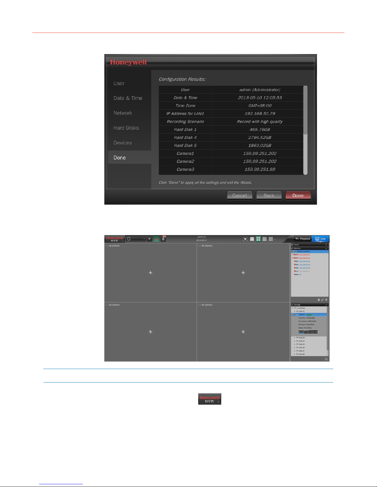
7. The “Done” tab displays the configuration results as shown in the following figure. To
modify any configuration, click Back to return to the target tab.
above window. Click Next to go to “Done” tab.
21
Page 28
Basic Operations
Figure 4-13 Done
8. Click Done to apply the new configurations. After applying the new configurations, the
system will exit the wizard and display the Live screen, as shown in the following figure:
Figure 4-14 Live Screen (First Login)
Switch User
To switch to another user, navigate to Switch User in the top left corner of Live
screen and click OK in the pop-up window as shown in the following figure:
22
Page 29

Figure 4-15 Switch User
Change Password
To change the password of current user’s, navigate to Change Password in the
top left corner of Live screen, and a window is displayed as shown in the following figure:
Figure 4-16 Change Password
Honeywell
Log Off
Input old password, new password and confirm password and then click OK.
To log off the system, navigate to Log Off in the top left corner of the Live
screen and click OK in the pop-up window as shown in the following figure:
23
Page 30

Basic Operations
Restart
Figure 4-17 Log Off
To restart the system, navigate to Restart in the top left corner of the Live
screen and click OK in the pop-up window as shown in the following figure:
Figure 4-18 Restart
Shutdown
After clicking OK, the screen displays a pop-up window and restarts several seconds later.
To shutdown the system, navigate to Shutdown in the top left corner of the Live
screen and click OK in the pop-up window as shown in the following figure or hold down the
ON/OFF switch for over 5 seconds on the front panel of the NVR (this method is not
recommended for data loss may occur).
24
Page 31

Figure 4-19 Shutdown
Recovery (Power Failure)
If the NVR crashes, restart the machine to resume the working condition.
If the NVR is shut down abnormally during recording, the current recorded
data might be lost.
Honeywell
Replacing the Button Cell Battery
It is recommended to use Lithium batteries of the same type (CR2032) to replace the old one.
To ensure the accuracy of the system time, replace the Lithium battery every two years.
Replace the battery when the NVR is powered off and then reset the system time after
restarting it.
25
Page 32

System Operation and Configuration
5 System Operation and Configuration
This chapter describes in detail how to view live video, play back, search and backup video
and set system configurations, etc.
Live
When successfully logged in, the Live screen is displayed. On this screen, you can view live
video, check alarm log, switch layout and scenario, manage cameras and disks, record
manually, control PTZ, etc.
To play the live video, drag the target camera icon from the “Devices” list to the target video
window. The Live screen is displayed as shown in the following figure:
Figure 5-1 Live Screen
26
After successfully logged in, all the connected cameras start scheduled
recording by default. To stop or set the scheduled recording, refer to the
“Record Setup” section on page 58.
Page 33

Honeywell
Click
shown in the following figure:
Figure 5-2 Main Menu
Table 5-1 Menu Function
in the top left corner on the Live screen and the main menu is displayed as
Name Function
Search&Backup
View Log
System Status
Record Setup
System Setup
Change Password
Switch User
Log Off
Restart
Enter the “Search&Backup” screen. Refer to the “Search and Back
Up” section on page 47.
Enter the “View Log” screen. Refer to the “View Log” section on page
50.
Enter the “System Status” screen. Refer to the “System Status”
section on page 55.
Enter the “Record Setup” screen. Refer to the “Record Setup” section
on page 58.
Enter the “System Setup” screen. Refer to the “System Setup”
section on page 61.
Change the current user’s password. Refer to the “Change
Password” section on page 23.
Switch to another user. Refer to the “Switch User” section on page
22.
Log off the current user. Refer to the “Log Off” section on page 23.
Restart the system. Refer to the “Restart” section on page 24.
Shut Down
Shut down the system. Refer to the “Shutdown” section on page 24.
27
Page 34

System Operation and Configuration
Video Window Operation
There are 6 (1/4/6/8/9/16 windows) window layouts. To switch the window layout, click
“Window Layout” on top of the Live screen.
Playing Live Video
Drag the target camera icon from the“Devices” list to the target video window, or click the
icon in the video window to select the target camera from the pop-up list to play the live
video.
Stop Playing the Live Video
Right click the video window and select “Stop Playing” in the pop-up menu.
Aspect Ratio
Right click the video window and select “Change the Aspect Ratio” in the pop-up menu.
Switch Stream
Right click the video window and select “Switch Stream” in the pop-up menu. (To enable this
option, both “High Quality” and “Standard Quality” should be selected when adding a cemera,
see “Adding a Camera” section on page 31).
Views Settings
Audio Switch
Move the cursor to the bottom of the current video window and a hidden tool bar is displayed.
Click
button to turn the audio on and off.
Digital Zoom
Move the cursor to the bottom of the current video window and the hidden tool bar is
displayed. Click
at bottom right corner to zoom in or out the selected area; drag the red frame to select the
area.
button to switch to single window and roll mousewheel in the zoom box
PTZ Control
Move the cursor to the bottom of the current video window and the hidden tool bar is
displayed. Click button to go to the PTZ control screen, see “PTZ Control” section on
page 40.
Full Window (1 Window)
Doble click the target video window to switch to full window layout; double click again to
return to the previous layout.
Views allow you switch multiple related live groups. You can create views to switch among
different live video groups. There are up to 16 live videos in a view and the created views are
listed in the right “Views” list. To play a view, drag a view icon from the “Views” list to the
video window. The “Views” list is as shown in the following figure:
28
Page 35

Honeywell
Figure 5-3 Views List
Creating a View
1. Select a layout from the “Window layout”;
2. Drag the target camera icon (up to 16 icons) from the “Deviecs” list to the video window;
3. Click
pop-up “New View” window, as shown in the following figure:
Figure 5-4 Creating a View
4. Close the keyboard after entering the name and click OK. The created view is displayed
in the “Views” list.
in the bottom right corner of the “Views” list and enter the view name in the
Editing a View
Take editing “South Squre” as an example: drag the icon of “South Square” from the “Views”
list to the video window, and then click in the bottom right corner of the “Views” list to
enter the editing mode, as shown in the following figure:
29
Page 36

System Operation and Configuration
Figure 5-5 Editing Mode
Refer to step 1 and 2 of “Creating a View” on page 29 to edit. To give up editing, click
When editing is done, click
window is displayed as shown in the following figure:
Figure 5-6 Editing a View
Click OK to save the change; or click Save As to create a new view with the old one
remained.
in the bottom right corner of the window and a pop-up
.
Removing a View
Select a view in the “Views” list and click in the bottom right corner and when the pop-up
window is displayed, click OK.
Device Operation
The “Devices” list is on the right side of the Live screen and displays the IP cameras
connected to this NVR. In the “Devices” list, you can add, edit, configure and remove the
camera or play the live video, record manually and play history video.
Device name in blue—online;
Device name in red—an alarm is occurring and the icon is displayed;
30
Page 37

Honeywell
Device name in gray—off line.
indicates the camera is now recording.
Figure 5-7 Devices List
Adding a Camera
Click in the bottom right corner of the “Devices” list and the “Add Devices” window is
displayed as shown in Figure 5-8
and “Import”. “Add” is for adding one designated camera; “Search” is for adding a batch of
designated cameras and “Import” is for importing a file containing parameters of cameras’ to
the NVR.
Add
Click “Add” tab in “Add Devices” window and then select “Device Type” and input the “IP
Address”, “Port”, “User”, “Password” and “Camera Name”, as shown in the following figure:
and there are three tabs in the window: “Add”, “Search”
31
Page 38

System Operation and Configuration
Figure 5-8 Add Camera
If you want to set stream, PTZ and multicast, click “Advanced Settings” in the above window
and the “Advanced Settings” window is displayed as shown in the following figure:
Figure 5-9 Advanced Settings
After the settings are finished, click OK and the added camera is displayed in the “Devices”
list.
Search
1. Click “Search” tab and select camera’s type from the dropdown list as shown in the
following figure:
32
Page 39

Honeywell
Figure 5-10 Search Camera
2. Click Search and then all the cameras of this type are listed. Click to turn page
down.
3. Check the target camera checkbox. Click Quick Add, when the pop-up window is
displayed, click OK to add the selected cameras to the “Devices” list; or click Next to
manually edit the parameters, see Figure 5-8.
Import
1. Connect a USB storage device with the file (.cvs) on it to the NVR.
2. Click “Import” tab on “Add Devices” screen as shown in the following figure:
Figure 5-11 Import Devices List
33
Page 40

System Operation and Configuration
3. Click Import devices list and the “Import File” window is displayed as shown in the
following figure:
Figure 5-12 Import File
4. Select USB device and target file (CVS file) and click OK to enter the “Choose
Cameras” window as shown in the following figure:
Figure 5-13 Choose Cameras
5. Check the target camera and click
6. Click Add, when the pop-up window is displayed, click OK to add target cameras to the
“Devices” list.
to turn page down.
34
Page 41

Honeywell
Editing a Camera
Select a camera in the “Devices” list (Figure 5-7) and click in the bottom right corner and
the following screen is displayed. You can modify the camera’s access parameters on this
screen.
Figure 5-14 Editing a Camera
If you want to set stream, PTZ and multicast, click “Advanced Settings” in the above window
and the “Advanced Settings” window is displayed as shown in the following figure:
Figure 5-15 Advanced Settings
After the settings are finished, click OK and the following pop-up window is displayed:
35
Page 42

System Operation and Configuration
Figure 5-16 Success
Click OK to close the window and exit.
Configuring a Camera
To configure the camera stream (Codec Type, Resolution, Frame Rate and Bit Rate), right
click the icon of the camera and select “Camera Configuration” in the pop-up menu, the
configuration window is shown as the following figure:
Figure 5-17 Camera Configuration
36
When the settings are finished, click Apply to save the new configuration and click Cancel
to close the window.
Removing a Camera
Select a camera by clicking its icon in the “Devices” list and click in the bottom right
corner; or right click the icon of the target camera and select “Remove” in the pop-up menu.
Playing Live Video
• Select a video window on the Live screen and then right click the icon of the target
camera in the “Devices” list and select “Live” in the pop-up menu;
• Drag the icon of the target camera to the designated video window.
Play back Video
Select a video window on the Live screen and then right click the icon of the target camera
in the “Devices” list and select “Playback” in the pop-up menu
Page 43

Honeywell
Manual Recording
On the Live screen, you can manually start/stop recording on a camera.
Start Manual Recording—Right click the icon of the camera and select RecordManual
Recording.
Stop Manual Recording—Right click the icon of the camera and select RecordStop
Recording.
Panic Recording
When a panic or duress condition occurs, you can start panic recording by using one button
or key. When panic recording is started, all the connected IP cameras start recording.
Perform one of the following two methods to start and stop the panic recording:
Storage
• Click
stop recording.
• Hold down the
panic recording; hold down it again for over 1 second to stop recording.
The “Storage” list displays the disk information. “Disk 01~08” indicate the corresponding disks,
and “e-SATA” indicates the optional eSATA disks. Click
including total size, free space, Read/Write type and status as shown in the following figure:
Figure 5-18 Storage
on the Live /Playback screen to start the panic recording; click it again to
key on the front panel (Figure 2-1 ) for over 1 second to start the
to view detailed information
To refresh the disk information, click
.
37
Page 44

System Operation and Configuration
• It is recommended that to eject the disk by user interface
operation, otherwise, it will damage the disk or cause data loss.
• It is recommended that the ejection interval between two disks is
not less than 30 seconds.
Read/Write Type
• To set a disk to READ-ONLY, right click the disk icon and select SetRead-Only.
• To set a disk to READ-WRITE, right click the disk icon and select SetRead-Write.
Ejecting Disk
To remove a disk from the NVR, right click the disk icon and select “Eject” in the pop-up
menu and the below window will be displayed:
Figure 5-19 Confirm Disk Ejection
Click OK to eject the disk. If it is the only available disk for recording then the below window
is displayed:
Figure 5-20 Eject
Click OK to stop recording and eject the disk.
• Do not directly pull out the disk during the ejection process.
• Do not remove the disk while it is still working to avoid losing data
and do not plug in the disk during system start up.
38
Page 45

Honeywell
Formatting Disk
To format a disk, right click the disk icon and select “Format” in the pop-up menu and then a
pop-up window is displayed:
Figure 5-21 Format
Click OK and wait until the message pops up indicating it is successful.
Do not directly pull out the disk during the formatting process.
Viewing S.M.A.R.T. Information
S.M.A.R.T. information is used to detect the status of the disk. To view the S.M.A.R.T.
information of a disk, right click the disk icon and select “S.M.A.R.T.” in the pop-up menu.
The information will be displayed in a window as shown in the following figure (Please
consult technicians):
Figure 5-22 S.M.A.R.T. Information
Click OK to close the window.
Viewing Properties
To view the disk properties, right click the disk icon and select “Properties” in the pop-up
menu. The information will be displayed in a window as shown in the following figure:
39
Page 46

System Operation and Configuration
Figure 5-23 Properties
“S.M.A.R.T.Evaluation” has two indexes: “Pass”/Failed”; “Whole Evaluation” has three
indexes: “Good”/ “Normal”/ “Poor”. If “W hole Evaluation” displays “Poor”, user should replace
the disk to avoid the data loss.
Click OK to close the window.
PTZ Control
PTZ function is only available for cameras equipped with PTZ device.
To enable PTZ function:
1. Select a camera in the “Device” list and click the
the popped up “Edit Camera” window, click “Advanced Settings”. In the “Advanced
Settings” window, enable the “PTZ” option. After clicking OK, the icon of the target
camera is changed to
2. Drag the target camera icon from the “Device” list to the video window.
3. Move the cursor to the bottom of the current video window and the hidden PTZ control
bar is displayed as shown in the following figure:
Figure 5-24 PTZ Control Bar
Click
to display the control interface as shown in the following figure:
.
icon in the bottom right corner. In
40
Page 47

Honeywell
Figure 5-25 PTZ Control Interface
Figure 5-26 PTZ Control
As shown in the above figure, click
to adjust the shooting direction; click to choose “Go to Preset” or “Save Preset”.
/ to get a zoomed in or zoomed out image; drag
Save Preset
A numeric figure represents a preset with a certain shooting direction. The number of presets
is decided by camera’s property.
Figure 5-27 Save Preset
To save a preset, adjust the shooting direction and image. Click
and click to choose a numeric figure in the box. Click Save.
to select “Save Preset”,
41
Page 48

System Operation and Configuration
Go To Preset
Figure 5-28 Go To Preset
Patrol
To turn the camera to an existing preset, click
choose the target numeric figure in the box. Click Go.
Click to exit PTZ control.
Patrol function can circularly play groups of live videos.
Click
Figure 5-29 Patrol List
Creating a Patrol
1. Click New Patrol in the above window and the “New Slide” window is displayed as
Configuration on the Live screen and the below window is displayed:
shown in the following figure:
Figure 5-30 New Slide
to select “Go to Preset”, and click to
42
Page 49

Honeywell
2. Enter the Slide Name in the text box and click OK.The “Edit” window is displayed as
shown in the following figure:
Figure 5-31 Edit Patrol
3. Click window layout icons in the top right corner to select the layout;
4. Click to select the camera in the pop-up window as shown in the following figure:
Figure 5-32 Add Camera
5. Click
6. Click Duration to select the time interval between two slides;
7. Click Save to create the patrol in the “Patrol List” window (Figure 5-29).
Editing a Patrol
To edit a patrol, select a patrol in the “Patrol List” (Figure 5-29) and click Edit to enter the
edit window (Figure 5-31). Refer to step 3 and 4 of “Creating a Patrol ”to edit a patrol.
Remove Patrol
To remove a patrol, select a patrol in the “Patrol List” (Figure 5-29) and click Remove.
Preview Patrol
on the right side of the above window to continue adding slide;
43
Page 50

System Operation and Configuration
To preview a patrol, select a patrol in the “Patrol List” (Figure 5-29) and click Preview, the
“Patrol Preview” window is displayed as shown in the following figure:
Figure 5-33 Patrol Preview
Playing a Patrol
To play a patrol, click
to enter the patrol mode as shown in the following figure:
Figure 5-34 Play Patrol
Click
to pause playing and click to stop playing and exit the patrol mode. To play
on the Live screen and select a patrol in the dropdown list. Click
patrol in full screen mode, first click
the list, click
Playback
Click on the Live screen to enter the Playback screen. On this screen, you can
play back recorded videos, search and backup videos. Three window layouts are supported
44
icon, and then click to select the target patrol in
icon to play.
Page 51

Honeywell
on this screen:
figure (4 windows):
Figure 5-35 Playback Screen
1 window, 4 windows and full screen as shown in the following
Video Window Operation
Playback
To play back video, drag the icon of the target camera from the “Devices” list to the video
window, or click the
list. The default start time of playback is 12:00 am.
Synchronous Playback
To control the four windows using the playback control from a same point of time, click
at the left top corner of the screen to enter the synchronous playback mode.
Independent Playback
To control one certain window using the playback control, select a video window and then
click
Stop Playback
To stop playback, right click the target video window and select “Stop Playing” in the pop-up
menu, or select “Stop Playing (All)” to stop all videos.
to enter the independent playback mode.
icon in the video window to select the target camera from the pop-up
45
Page 52

System Operation and Configuration
Change the Aspect Ratio
Right click the video window and select “Change the Aspect Ratio” in the pop-up menu to
switch the aspect ratio of the current video window.
Codec Type
Right click the video window and select “Codec Type (H.264/MJPEG)” in the pop-up menu.
Playback Control
Playback control is at the bottom of this screen as in the figure below:
Figure 5-36 Playback Control
Table 5-2 Playback Control
Name Function
Timeline
Video Strip
Axis
Time Line Scale
Mute/Volume Enable mute or adjust volume.
Digital Zoom
Play/Pause Click to start or pause the video playing.
Display the time scale.
The video strip with different colors represents different types of video:
green—scheduled recording;
blue—manual recording;
yellow—video event;
red—alarm recording.
Drag the video strip to select the video start time that the axis
indicates.
The playback time of video. The date and time is displayed below,
which can be clicked to expand the calendar and the date in color
represents there is a recording on that day.
The time unit is adjustable from 5 seconds to 30 minutes.
Select a video window and click this button to enter full screen mode.
The cursor is presented as
to zoom in or out.
in the preview box and scroll the mouse
Backward/Pause
46
Click to start or pause reversed playing.
Page 53

Honeywell
Play the video at a lower speed. Each click on the button switches to a
Speed Down
Speed Up
different level of speed (2 levels: 1/4x and 1/2x). When the current
speed is 1/4x, clicking the button again to restore to the normal speed.
Play the video at a faster speed. Each click on the button switches to a
different level of speed (4 levels: 2x, 4x, 8x and16x). When the current
speed is 16x, clicking the button again to restore to the normal speed.
Previous Frame
Next Frame When paused, click to go to the next frame.
Speed
Search and Back Up
This NVR can search and back up video by search conditions.
Filter
To filter videos on the Playback screen, specify the target time and event type in the “Filter”
window as shown in the following figure:
Figure 5-37 Filter
When paused, click to go to the previous frame.
Display the current play speed. 1x represents the normal speed.
Click Default to select “All Events”. Click Filter, then the video window plays the video
matching the search conditions. Click Advanced to enter the Search & Backup screen (see
“Search and Back Up” section on page 47.).
Search Videos
Follow the operations below to search video:
1. Click Advanced in the “Filter” window (Figure 5-37) or navigate to
Search&Backup on the Live screen. The following screen is displayed:
47
Page 54

System Operation and Configuration
Figure 5-38 Search & Back Up
2. Specify the target time, camera, codec and event in the “Filter” window and the target
video is displayed as shown in the below figure:
Figure 5-39 Seach Result
3. Select and drag the target video strip (marked with white dashed line) to specify the
playback start time. The “Preview” window displays the image you select as shown in
the below figure:
Figure 5-40 Preview
4. Click Playback in the “Preview” window (Figure 5-40) to skip to the Playback screen to
play back the target video.
48
Page 55

Back Up Videos
Video clips can be backed up to an external USB storage device. There are two methods of
backup:
• Back up on the Search&Backup screen:
Figure 5-41 Back Up Video
Figure 5-42 Export Video Clips
Honeywell
1. Search the target video by conditions; see “Search Video” section on page 47.
2. Drag on the timeline (marked with red box) to specify the time period to be backed
up (in yellow) and select the target cameras as shown in the following figure:
3. Click Show Size in the bottom left corner of this screen to view the video size.
4. Click Export in the bottom right corner or right click the selected area and select
“Export to” in the pop-up menu. The “Export Video Clips” window is displayed:
5. Select the target device and format.Click Start to export the video clips.
• Back up on the Playback screen:
1. Drag the camera icon to the video window.
2. Drag on the timeline (marked with red box) to specify the time period to be backed
up (in yellow) as shown in the following figure:
Figure 5-43 Back Up Video on Playback Screen
3. Right click the selected are and select “export to” in the pop-up menu. The “Export
Video Clips” window is displayed:
49
Page 56

System Operation and Configuration
Figure 5-44 Export Video Clips on Playback Screen
4. Select the window that the target camera represents (1, 2, 3 and 4 respectively
represents the video window).
5. Select the target device and format. Click Start to export the video clips.
View Log
Operation Log
The video format is. “avi”, named as “chn-1_2013-6-20-12-11-39_2013-620-12-27-27”. Video files greater than 1G will be splited into multiple files.
The system contains an Operation Log and an Alarm Log and can store up to 5000 piece of
logs respectively.
To view the Operation Log, navigate to View LogOperation Log on the Live
screen and the following screen is displayed:
50
Page 57

Honeywell
Figure 5-45 Operation Log
Alarm Log
Click
designated page, click the cursor in the text box and scroll the mouse wheel to select the
target page number and click Go. Check the “Date&Time” in the top left corner to select the
target date to be viewed in the pop-up calendar; click “All” to select the target type in the
dropdown list.
Click Backup to back up the entire log to the external USB device or click Remove to delete
the entire log.
The numeric figure on represents the number of unread alarm log, for example: . It
only displays when “Show Messeage” is enabled (see Figure 5-63 and Figure 5-87 on page
61 and 70). Click
the read ones are in black as shown in the following figure:
to turn to the next page; click to skip to the last page. To skip to the
to display the “Alarm Log” window. The unread logs are in orange and
51
Page 58

System Operation and Configuration
Figure 5-46 Alarm Log
Click on an unread log and the figure below is displayed:
Figure 5-47 Log Expanded
Click to play the live video of the related camera; click to play back the recorded
video of the related camera.
Click in the top right corner of “Alarm Log” window (Figure 5-46 ), the sub menu is
displayed:
52
Page 59

Honeywell
Figure 5-48 Alarm Log-Menu
“Configure Trigger Profiles”, see the “Trigger Profiles (Alarm Recording)” section on page 59;
“Configure System Alarm”, see the “System Alarm” section on page 70;
Select “Export” to export the target log to the external USB device or click “Remove All” and
the below window is displayed:
Figure 5-49 Remove All Alarm Log
Click OK to remove all alarm log.
Input Alarm Log
Navigate to View LogAlarm LogInput Alarm Log on the Live screen to
view the input alarm log as shown in the following figure:
53
Page 60

System Operation and Configuration
Figure 5-50 Input Alarm Log
Click
page, click the text box and scroll the mouse wheel to select the target page number and
click Go. Check the “Date&Time” in the top left corner to select the target date to be viewed
in the pop-up calendar; click “All” to select the target type in the dropdown list.
Click Backup to back up the entire log to the external USB device or click Remove to delete
the entire log.
to go to the next page; click to skip to the last page. To skip to the designated
System Alarm Log
Navigate to View LogAlarm LogSystem Alarm Log on the Live screen to
view the system alarm log as shown in the following figure:
Figure 5-51 System Alarm Log
54
Page 61

Honeywell
Click
page, click the text box and scroll the mouse wheel to select the target page number and
click Go. Check the “Date&Time” in the top left corner to select the target date to be viewed
in the pop-up calendar; click “All” to select the target type in the dropdown list.
Click Backup to back up the entire log to the external USB device or click Remove to delete
the entire log.
System Status
To view the performance status of the running system, navigate to System
Status.
Basic Status
The “Basic Status” window is displayed by default as shown in the following figure:
Figure 5-52 Basic Status
to go to the next page; click to skip to the last page. To skip to the designated
Network Status
Click on “Network Status” in the above window and then below window is displayed:
55
Page 62

System Operation and Configuration
Figure 5-53 Nerwork Status
Click Receiving in the above window to view the parameters of data being received and
click Transmitting (right next to Receiving button) to view the parameters of data being
sent.
Figure 5-54 Receiving/Sending Chart
56
Page 63

Honeywell
In the above window, Y-axis represents the network flow (Mbps) and the X-axis represents
the time (200 Ms).
Figure 5-55 Bit Rate Chart
In the above window, the column with grey writing represents the camera and the column
with yellow writing represents the bitrate of the camera (Kbps).
Hard Disk Status
Click on the “Hard Disk Status” column and the following window is displayed:
Figure 5-56 Hard Disk Status
Click the S.M.A.R.T. column for details.
57
Page 64

System Operation and Configuration
Record Setup
This NVR supports manual recording, scheduled recording, panic recording and alarm
recording. This section describes scheduled recording and alarm recording. For manual
recording and panic recording, please refer to the “Manual Recording” section on page 37
and the “Panic Recording” section on page 37.
Scenario Mode (Scheduled Recording)
Scheduled recording enables the camera to start/stop recording automatically according to
the set time.
Navigate to
“High quality recording”, “Low quality recording” and “My favorite scenario mode” on the pop
up window.
Under “My favorite scenario mode” there are three scenarios for selection: “Working day
scenario”, “Holiday scenario” and “My favorite scenario” as shown in the following figure:
Figure 5-57 Select Scenario Mode
Record SetupScenario Mode on Live screen, and you can select
This screen contains the following settings:
High quality recording —enables main stream recording to ensure high resolution image
but with larger size.
Standard quality recording —enables auxiliary stream recording to ensure small size
image but with low resolution.
When the hard disk is full—set to overwrite / stop recording while the disk is full.
My favorite scenario —there are three scenarios for selection: “Working day scenario”,
“Holiday scenario” and “My favorite scenario”.
Follow the operation below to set scheduled recording:
58
Page 65

Honeywell
1. Select a scenario under “My favorite scenario” and click
displayed:
Figure 5-58 Scenario Mode
Target Day—Selects the day to be set in the dropdown list.
0~23—Represents 24 hours. Each square is for half an hour.
1~7—Represents cameras.
Copy this schedule to—Select the target day to which the schedule is going to be
copied to in the dropdown list.
High Quality—Enables main stream recording to ensure high resolution image but with
larger size, colored in blue.
Standard Quality—Enables auxiliary stream recording to ensure small size image but
with low resolution, colored in green.
Off—Cancel the schedule.
2. Click on the corresponding square or drag an area and select “High Quality” / “Low
Quality” / “Off” in the popped up menu as the figure below:
Figure 5-59 Recording Mode Selection
, the following figure is
The green square in the above figure represents “the selected camera will start
recording with low quality mode at 5:30~6:00 on Monday”. Replicate this method to set
the other cameras. When finished, click Save&Back to return to Figure 5-57.
To select the recording mode, user should first add the corresponding
recording stream to the camera, see Figure 5-9.
Trigger Profiles (Alarm Recording)
When specific events occur, the system will launch related cameras into recording.
Navigate to
Record SetupTrigger Profiles and the below figure is displayed:
59
Page 66

System Operation and Configuration
Figure 5-60 Configure Trigger Profiles
New Profile
1. Click New Profile and click in the pop-up “Alarm Device” window to add alarm
device.
2. Click on the added alarm device to select the trigger condition in the dropdown list;
3. Click
following figure:
Figure 5-61 Add Alarm Device and Triggered Device
4. Configure the added device in “Camera Settings” window. To remove a device, select
that row and click Remove, as shown in the following figure:
Figure 5-62 Camera Settings
5. Configure “Alarm Output”, “Show Message” and “Audible Alarm” in “System Settings”
window as the figure below:
in “Triggered Device” window to add triggered device, as shown in the
60
Page 67

Honeywell
Figure 5-63 System Settings
6. Set Pre-Recording and Post-Recording: Pre-Recording—starts recording a few
seconds before triggered alarms; Post-Recording—continues recording a few seconds
after the alarm event occurs.
Click Save Profile in Figure 5-63. The new profile is displayed in the “Alarm Profile” list as
shown in the following figure:
Figure 5-64 Alarm Profile List
Edit
To edit a profile, select that row and click Edit in “Alarm Profile” list (Figure 5-64), refer to
“New Profile” operation.
Remove
To remove a profile, select it and click Remove in “Alarm Profile” list (Figure 5-64).
System Setup
This section describes the settings and related operations.
General Settings
Navigate to System SetupGeneral Settings and the below figure is displayed:
61
Page 68

System Operation and Configuration
Figure 5-65 General Settings
In the above window, you can view and modify the settings of the “Current User”, “Audio”,
“Network-Lan1”, “Date&Time”, etc.
System Settings
Click System Settings in Figure 5-65 to enter the System Settings screen and where there
are 4 options: “Date and Time”, “Audio”, “System Management” and “System Information” as
shown in the following figure:
Figure 5-66 System Settings
Date and Time
Click the “Date and Time” and the below window is displayed:
Figure 5-67 Date and Time
62
Page 69

Honeywell
In the above window, you can set time zone, date, time and whether to synchronize with
NTP automatically. Click Advanced Settings and the below window is displayed:
Figure 5-68 Advanced Settings
You can set date and time format, NTP server and port.
Enable “DST” (Daylight Saving Time) option to display the window as in the following figure:
Figure 5-69 DST
Audio
Click the “Audio” to enable mute and adjust volume as shown in the following figure:
Figure 5-70 Live Audio
Only when “Live Audio” option on this screen is enabled, can user adjust the volunm on Live
screen.
System Management
Click “System Management” and the below window is displayed:
63
Page 70

System Operation and Configuration
Figure 5-71 System Management
You can upgrade firmware, restore to factory/default settings, export/import configuration file
and enable auto log off.
Upgrade Firmware Steps
1. Copy the upgrade file (“.hdu” file) into a USB storage device and connect it to NVR.
Click Upgrade Firmware in the window above.
2. In the pop up window, select the upgrade file and click OK. It will display the version
information of the current system and the upgrade file.
3. Click OK to start upgrade and wait until it shows that the upgrade is complete.
4. Click OK and a message pops up to ask for a system restart to apply the new
firmware version.
Export Configuration File
To export the configuration (except for the IP address setting) file to an external USB device,
click Export in the above window and the below window is displayed:
Figure 5-72 Export
Select the target USB device and file and then click OK to start exporting the configuration
file (Config_export.hdc) and wait until it shows that the exporting is complete.
Import Configuration File
To import a configuration file, copy the configuration file (“.hdc” file) into a USB storage
device and connect it to the NVR. Click Import as shown in Figure 5-71 and the below
window is displayed:
64
Page 71

Honeywell
Figure 5-73 Import
Select the target file and then click OK to start importing the configuration file. When finished,
the system will restart automatically to apply the new configuration.
System Information
Click “System Information” to view information such as model name, serial number, firmware
version, etc., as shown in the following figure:
Figure 5-74 System Information
Display Settings
Click Display Settings in Figure 5-65 to enter the Display Settings screen and where there
are 3 options: “Basic”, “Image” and “Patrol” as shown in the figure below:
Figure 5-75 Display Settings
65
Page 72

System Operation and Configuration
Basic
Click “Basic” to view and modify User Interface language, resolution and Local On-screen
Display as shown in the following figure:
Figure 5-76 Display
Image
Click “Image” and select HDMI/VGA or CVBS to modify image parameters as shown in the
following figure:
Figure 5-77 Image Parameters
User Settings
Patrol
See “Patrol” section on page 42.
Click User Settings in Figure 5-65 to enter the User Settings screen and where there are 2
options: “User Management” and “Role Authority” as shown in the following figure:
Figure 5-78 User Settings
User Management
Click “User Management” to view the basic information of current selected user, reset
password, etc., as shown in the following figure:
66
Page 73

Honeywell
Figure 5-79 User Management
New User
Click New User in the above window and the “New User” window is displayed:
Figure 5-80 New User
Enter the User Name, Password, and select Role, click OK.
Edit User
To edit a user, click Edit in the “User List” window (Figure 5-79) and the “Edit” window is
displayed:
• If a message pops up indicating the name already exists, it means
the name entered for the new user has been occupied. Click OK to
close the message and enter a different name for the user.
• The NVR supports a maximum of 32 users. If a message pops up
indicating that the maximum number of users has been reached, you
cannot create any new users. You will need to delete users before
adding new ones.
67
Page 74

System Operation and Configuration
Figure 5-81 Edit
You can modify the “Role” in the above window.
Remove User
To remove a user, select a target user in the “User List” window (Figure 5-79) and click
Remove.
The three default users (guest, operator and admin) cannot be removed.
Reset Password
Click Reset Password in the above window to reset to default password.
Only “Administrator” user has the authority to reset the password.
Role Authority
Click “Role Authority” to check and set authorities of “Operator” and “Guest” users. “Admin”
user can not be edited.
Figure 5-82 Role Authority
68
Page 75

Network Settings
Click Network Settings in Figure 5-65 to enter the Network Settings screen and where
there are 3 options: “Basic”, “Multicast” and “HUS VMS” as shown in the following figure:
Figure 5-83 Network Settings
Basic
Honeywell
Only “Administrator” user is able to manage role authority options.
Click “Basic” and the below window is displayed:
Figure 5-84 Network Settings
This screen contains the following items:
Obtain an IP address automatically— Select it to automatically retrieve IP address via the
DHCP server. Click Save and it displays “IP Address”, “Mask” and “Gateway” values after a
few seconds. Make sure NVR has access to the DHCP server which is running on the
Ethernet network.
Use the following IP adress—Select it to allow user to configure “IP address”, “Subnet
Mask” and “Gateway” manually.
Max User(s) — Specify the maximum number of simultaneously on-line users allowed (≤32
users).
When finished, click Save.
Network Failure Recovery—Click to enble this function. When it is enabled, all the cameras
start 7*24 hours manual recording.
69
Page 76

System Operation and Configuration
When changing the IP settings, it will stop the video tasks of current IE client and display a
message, click OK to proceed and apply the new settings.
Multicast
To set a channel to multicast stream, click “Multicast” and the below window is displayed:
Figure 5-85 Multicast
In the above window, you can enable multicast, set the beginning IP address, etc.
Alarm Settings
Click Alarm Settings in Figure 5-65 to enter the Alarm Settings screen and where there
are 3 options: “System Alarm”, “Alarm Output” and “Alarm Input” as shown in the following
figure:
Figure 5-86 Alarm Settings
System Alarm
Cliclk “System Alarm” to set “Alarm Output”, “Show Message” and “Audible Alarm” when
related events ocurr.
Figure 5-87 System Alarm
70
Page 77

Honeywell
Alarm Output
Click “Alarm Output” to set “Trigger Type” and “Duration” as the figure below:
Figure 5-88 Alarm Output
Alarm Input
Click “Alarm Input” to set the alarm input status as the figure below:
Figure 5-89 Alarm Input
71
Page 78

NVR Internet Explorer (IE) Client
6 NVR Internet Explorer (IE) Client
NVR can be accessed and controlled from the IE Client via the network. On the IE Client, all
the settings of NVR’s on-screen menu can be implemented except for “Wizard”, “Views”,
“Patrol” and “Synchronous Playback”.
• Make sure that NVR is connected to the network correctly.
System Requirements
• Supports Internet Explorer 9.
• CPU: Intel® i5 750 2.66 GHz
• System Memory: 4 GB
• Optical Drive: DVD-R
• HDD: 250G,Ensure 20G available space
• Network Interface Card: Dual or compatible pair of NICs, 1 Gbps
• Keyborad: 102-key keyboard and a mouse pointing device
• Graphics Adapter: NVIDIA 1GB Independent Graphic Card
• Operating System
a. Window
b. Microsoft
®
7 Professional 32-bit/ Window® 7 Enterprise 32-bit
®
.Net Framework 4.0
Internet Explorer Configuration
Before any operation of NVR IE Client, you need to enable ActiveX controls and plug-ins of
the Internet Explorer.
1. Take Internet Explorer 9 as an example. Right click on the blank space on the top of the
browser and check the “Menu bar” item in the text menu.
72
Page 79

Honeywell
Figure 6-1 Display Menu Bar
2. On the browser menu bar, open ToolsInternet options and select the “Security” tab,
as shown in the following figure.
Figure 6-2 Internet Options—Security
3. Click Custom Level… and the following window is displayed:
73
Page 80

NVR Internet Explorer (IE) Client
Figure 6-3 Security Settings—Internet Zone
Check the options marked in red frame as shown in the above figure. Click OK.
4. In Figure 6-2, select “Local Intranet” and click Custom Level…. The following window is
displayed:
Figure 6-4 Security Settings—Local Intranet Zone
Check the options marked in red frame as shown in the above figure. Click OK.
74
Page 81

Honeywell
5. Compatibility View Settings: Open Tools Compatibility View settings. The following
window is displayed:
Figure 6-5 Compatibility View Settings
Login
6. Deselect “Display Intranet sites in Comatibility View” and “Display all websites in
Compatibility View”.
1. Enter the IP address of the NVR in the address bar of Internet Explorer
http://192.168.1.90/
(e.g.
Figure 6-6 Security Warning
2. Click Install. When the installation is completed, the login window is displayed:
). For the first time login, the following window is displayed:
75
Page 82

NVR Internet Explorer (IE) Client
Figure 6-7 Login
Select the user name and enter the password. Click Login.
When successfully logged in, the Live screen is displayed.
Playing Live Video
Follow one of the operations below to play live video:
• Drag the target camera icon from the“Devices” list to the target video window.
• Click the icon in the video window to select the target camera from the pop-up list.
• Select a camera icon in the “Devices” list. Click the
pop-up menu.
Figure 6-8 Live Screen (IE Client)
icon and select “Live” in the
76
Page 83

Local Record
Honeywell
“Local Record” function is for Internet Explorer (IE) Client only. It can manually record the
visible live video and save to the computer.
Click
figure:
Figure 6-9 Local Record
Save To—click Browse to choose the path to save the recorded video clips.
Disk Usage Limit—set a valid value in the text box (the value must be an integer no less
than 1024). When the free disk space of the computer is less than the value, the disk will
“Overwrite old data” or “Stop recording”.
Disk Warning—check it to enable this option. Set a valid value in the text box. When the
free disk space of the computer is less than the value, the client will give a warning.
(Record Setup) on the Live screen and select “Local Record” in the following
77
Page 84

NVR Internet Explorer (IE) Client
Local Playback
“Local Playback” function is for Internet Explorer (IE) Client only. It can play back the video
clips that saved in the computer.
Follow the operations below to play back local video clips:
1. Drag the target camera icon from the“Devices” list to the target video window on the
Playback screen.
2. In the “Filter” window, select “Local” option and click Filter button as shown in the figure
below:
Figure 6-10 Local Playback
78
Page 85

Honeywell Security, Your Partner of Choice
Honeywell Security
Honeywell Security Asia Pacific
35F Tower A, City Center, 100 Zun Yi Road, Shanghai 200051, China
TEL +86 21 22196888
FAX +86 21 62370740
©2013 Honeywell International Inc. All rights reserved.
Honeywell
http://www.asia.security.honeywell.com
 Loading...