

Page 1
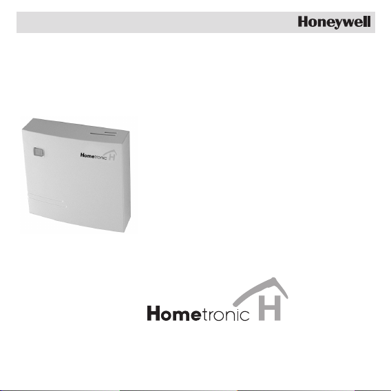
Device Switch
HS 30
Mounting
Page 2

Page 3

Contents
Contents
Contents 1
Overview 3
Application 3
Mounting 4
Laying cables 4
Connecting loads and pushbuttons 5
Teach-in 8
Activating the Teach-in mode at the switch module 8
Assignment to Hometronic Manager HCM 200 9
Assigning device switch HS 30 to Hometronic Manager as a
device 10
Installing device switch HS 30 at Hometronic Manager as a
collection relay of thermostat control 11
Installing device switch HS 30 at Hometronic Manager for
boiler request (HK 10) 14
Successful Teach-in 15
Final mounting 16
Operating 17
Device switch HS 30 as a collection relay of thermostat
control 18
Device switch HS 30 as collection relay of boiler feedback
set HK 10 18
1
Page 4

Contents
Appendix 19
Glossary 19
Technical data 20
Help with problems 21
Information for the fitter 21
2
Page 5
Overview
Overview
For your information
Technical terms are explained in the glossary (Page 19). They are
identified in the text by an *.
Application
The switch module HS 30 is a component of the Honeywell home
automation system. It switches electrical loads* such as lamps, radios,
humidifiers, etc.
For information on how the device switch can be used for the
thermostat control, read from Page 18.
For information on how the device switch can be used for the
boiler request, read from Page 14.
The switch module is designed for surface mounting on a distribution
box of the device circuit.
The connected loads* can be operated by the following means:
• with the integrated pushbutton
• with an installed pushbutton/switch on site
• with the Hometronic Manager
• with the Hometronic Remote control
The switching state (ON/OFF) is indicated by an LED behind the
transparent button.
3
Page 6
Mounting
Mounting
Danger to life through electric shock!
Live electrical contacts lie open while the module is
Danger!
being cabled. Touching a live contact causes critical
injuries.
► All work may only be carried out by authorized
technical personnel.
► De-energize the corresponding fuse during all work on
the module*.
The switch module has a radio receiver whose function
can be impaired by metallic objects and radio devices.
Caution!
Laying cables
► Lengthen the cables so that they protrude at least 10 cm out of the
distribution box.
4
► When selecting the operation site ensure that there is
sufficient distance to metallic objects such as metal
cabinets and doors, concrete ceilings with iron lattices
and radio devices such as radio headphones, etc.
Page 7
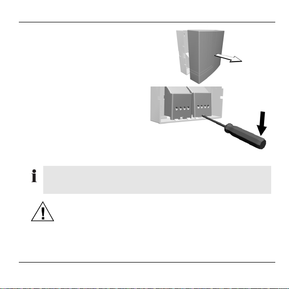
► Remove the housing cover
from the module.
► Lever the contact covers out
with a screwdriver.
► Insert all the cables through
the openings in the housing
bottom.
Connecting loads and pushbuttons
Both pushbuttons and switches can be connected to the
switch module. Pushbuttons should preferably be used for
new installations.
Malfunctions due to contact erosion
Caution!
► Replace old pushbuttons/switches by new
pushbuttons.
► Only use pushbuttons which are designed for 230 V
and conform to the VDE guidelines.
Mounting
5
Page 8
Mounting
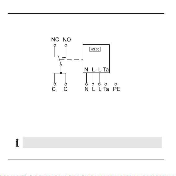
The following figure shows the circuiting for connecting pushbuttons/
switches and loads. The designations of the connections are also
used in the further description of the mounting.
Ta: Pushbutton connection L: Phase
C: Common (relay grouping) N: Neutral conductor
NO: Normally Open PE: Protected earth conductor
NC: Normally Closed
The relay contacts (C, NC, NO) are floating contacts.
No terminal is planned for the protective earth conductor.
6
Page 9

Mounting
► Connect the pushbutton
(switch) and the supply
voltage to the right-hand
terminal block in accordance
with the schematic.
LN LTa
► Loop the PE conductor through the flush-mounted box to the motor.
► Connect the load to the left-
hand terminal block in
accordance with the
schematic.
No
Nc
CC
► First fasten the housing bottom temporarily at the intended mounting
site so that corrections can be carried out later if required.
► Switch on the switch module.
The LED at the switch module lights up green.
7
Page 10

Teach-in
Teach-in
The new Hometronic components first have to be assigned to the
Hometronic Manager before they can be taken into operation. This
process is called the "Teach-in". The Hometronic Manager and the
new components exchange data during the procedure.
Activating the Teach-in mode at the switch module
► Keep the button at the switch module pressed for 10 seconds.
The LED flashes red regularly. The Teach-in mode at the switch
module is activated.
The Teach-in mode can be aborted by pressing the button at
the switching module briefly.
LED display at the switch module during the Teach-in
Display Meaning
LED flashes red Teach-in not carried out
LED blinks red Teach-in mode (duration 4 minutes)
LED off Teach-in successful
LED lights up red with
short breaks
8
Teach-in failed
Page 11

Assignment to Hometronic Manager HCM 200
Switching to "Settings" submenu of Hometronic Manager
The Hometronic Manager is in automatic mode.
The display* at the Hometronic Manager
shows the standard display (example):
► Press the Dial button.
The cursor* flashes in the lowest line.
► Turn the Dial button to the right until
"Menu" is selected.
► Press the Dial button.
The following text is displayed:
► Turn the Dial button to the left until
"Settings" is selected.
► Press the Dial button.
The following text is displayed:
The Hometronic Manager is in the "Settings" submenu.
HOMETRONIC
WE 29.10.1999 11:15
No Lifestyle active
LIVING 20.0 C
HOMETRONIC
WE 29.10.1999 11:15
No Lifestyle active
LIVING 20.0 C
LIFESTYLE
TIME PROGRAMS
DISPLAY
SETTINGS
INSTALLATION
DE-INSTALLATION
FUNCTION EXTENSION
SENSOR FUNCTION
Teach-in
9
Page 12

Teach-in
Assigning device switch HS 30 to Hometronic Manager as
a device
In the following example a humidifier is assigned to the switch module.
► Change to the "Settings" submenu as described on Page 9.
► Turn the Dial button until "Installation"
is selected.
► Press the Dial button.
The following text is displayed:
► Turn the Dial button to the left until
the "Devices/Light" submenu is
selected:
► Press the Dial button.
The module names are displayed.
► Turn the Dial button to the left until
the corresponding module is
selected, e.g.: "Humidifier".
10
HEATING/COOLING
SHUTTERS
DEVICES/LIGHT
SENSOR
HEATING/COOLING
SHUTTERS
DEVICES/LIGHT
SENSOR
MODULE-1
MODULE-2
HUMIDIFIER
CEILING LIGHT
MODULE-1
MODULE-2
HUMIDIFIER
CEILING LIGHT
Page 13

Teach-in
► Press the Dial button.
An * appears after the "Humidifier"
module.
► Activate Teach-in mode at the socket switching module within four
minutes (see Chapter "Activating the Teach-in mode at the switch
module" on Page 8).
MODULE-1
MODULE-2
HUMIDIFIER *
CEILING LIGHT
If "Q" is displayed after a module name, this module has
already been assigned to the Hometronic Manager. The process of assigning or changing module names is described in
the operating instructions of the Hometronic Manager.
Installing device switch HS 30 at Hometronic Manager as
a collection relay of thermostat control
Installation of the collection relay (HS 20 or HS 30) has no
effect on the maximum number of devices at the Hometronic
Manager HCM 200.
Example: Installing device switch HS 30 as a collection relay.
► Activate Teach-in mode at the HS 30 as described on Page 8.
► Change to the "Settings" submenu as described on Page 9.
11
Page 14

Teach-in
► Turn the Dial button until
"Installation" is selected.
► Press the Dial button.
The following text is displayed:
► Turn the Dial button to the left until
"Boiler request" is selected.
► Press the Dial button.
The following text is displayed:
HEATING/COOLING
SHUTTERS
DEVICES/LIGHT
SENSOR
SENSOR
SETPOINT ADJUSTER
ROOM CONTROL
BOILER REQUEST
SWITCHING MODULE
ANTI-FREEZE SENSOR
THERMOSTAT
► Turn the Dial button to the left until
"Thermostat" is selected.
► Press the Dial button.
An "*" appears after the
"Thermostat" entry. The device
SWITCHING MODULE
ANTI-FREEZE SENSOR
THERMOSTAT
SWITCHING MODULE
ANTI-FREEZE SENSOR
THERMOSTAT *
switch is assigned.
The socket switching module HS 30 is installed as a collection relay.
12
Page 15

Uninstalling collection relay
► Change to the "Settings" submenu (refer to Page 9).
► Turn the Dial button until "De-
Installation" is selected.
► Press the Dial button.
The following text is displayed:
► Turn the Dial button to the left until
"Boiler request" is selected.
HEATING/COOLING
SHUTTERS
DEVICES/LIGHT
SENSOR
SENSOR
SETPOINT ADJUSTER
ROOM CONTROL
BOILER REQUEST
► Press the Dial button.
The following text is displayed:
SWITCHING MODULE *
ANTI-FREEZE SENSOR
THERMOSTAT *
Teach-in
► Turn the Dial button to the left until
"Thermostat" is selected.
► Press the Dial button.
The "*" after the "Thermostat" entry
disappears.
The collection relay is uninstalled.
SWITCHING MODULE *
ANTI-FREEZE SENSOR
THERMOSTAT *
SWITCHING MODULE
ANTI-FREEZE SENSOR
THERMOSTAT
13
Page 16

Teach-in
Installing device switch HS 30 at Hometronic Manager for
boiler request (HK 10)
Installation of the collection relay (HS 20 or HS 30) has no
effect on the maximum number of devices at the Hometronic
Manager HCM 200.
► Connect the switch module to the cable of the boiler control (refer to
Page 5).
► Activate the Teach-in at the switch module (refer to Page 8).
► Change to the "Installation" submenu at the Hometronic Manager
(refer to Page 8).
► Turn the Dial button to the left until
the "Boiler demand" menu item is
selected.
The following text is displayed:
► Press the Dial button.
The following text is displayed:
After the Teach-in has been completed, the switch module is used for
the boiler demand.
14
SHUTTERS
DEVICES/LIGHT
SENSOR
BOILER DEMAND
SWITCHING MODULE *
ANTI-FREEZING SENSOR
Page 17

Successful Teach-in
–
–
If Teach-in was successful, the LED at the switch module
extinguishes.
Failed Teach-in
If the LED at the switch module lights green with short breaks,
the Teach-in has failed.
► Improve the transfer, avoid disturbances or shieldings, for
example, by:
Wireless headphones, garage door opener, remote
controls, metal parts
If possible, change the position of the switch
module.
► Repeat the Teach-in (starting from Page 8).
Teach-in
15
Page 18

Final mounting
Final mounting
► Remove the housing cover again.
► Clamp the contact covers in
the housing bottom.
► Screw the housing bottom
onto the flush-mounted box
or to the wall in accordance
with the drilling scheme.
16
Page 19

Operating
► Slide the housing cover onto
the housing bottom.
► Ensure that the housing cover
latches in.
Mounting has been completed.
Operating
The switch position of the relay output of the HS 30 is operated by
means of the built-in buttons or additional connected switches.
• LED green: contact C-NO (make contact).
• LED off: contact C-NC (break contact).
• LED red: communication error between Hometronic
Manager and the switch module.
17
Page 20

Operating
Device switch HS 30 as a collection relay of thermostat
control
A device switch HS 30 can be used (as a collection relay) for
feedback of the heat generation with thermostat control. The collection
relay switches the boiler on as soon as a relay in a zone under
thermostat control is activated.
Device switch HS 30 as collection relay of boiler feedback
set HK 10
The Hometronic Manager sends a request signal to the collection
relay HS 30 at a set boiler setpoint. The selectable boiler setpoint
(18 °C is preset) is specified in the parameter list of the HCM 200.
The boiler setpoint is constantly compared with the room setpoint
temperatures of the installed zones. The collection relay HS 30 is
switched on as soon as the room setpoint temperature of a zone
exceeds the boiler setpoint. The collection relay is switched off again if
all of the room setpoint temperatures are below the boiler setpoint.
For information on installing and setting the thermostat
control, refer to the operating instructions of the Hometronic
Manager HCM 200.
18
Page 21

Appendix
Glossary
Automatic mode
Standard operating mode of the
Hometronic Manager. All the
assigned areas are controlled
by means of time programs.
Boiler demand
Signal that the Hometronic
Manager sends to the heating
boiler when the setpoint drops
below the minimum value.
Connected load
Intake power of the plugged-in
device.
Load
Device which is connected to
the Hometronic component
(e.g. coffee machine, lamp,
radiator) and which consumes
power.
Appendix
Lifestyle
A certain combination of setpoints.
Presence simulation
The operation course of the last
7 days is repeated.
Time program
A sequence of setpoints and
corresponding switching points.
You specify a time program for
every module or every room.
Teach-in
The process of assigning a
model to the Hometronic
Manager.
19
Page 22

Appendix
Technical data
Operating voltage 230 V AC, 50 Hz
Intake power 3 VA
Operating temperature 0...50 °C
Degree of protection IP 30
Storage temperature –20 °C...+70 °C
Maximum humidity 95 %, non-condensing
Limiting data of the connected load
Min. load 0.01 A / 5V DC/AC
Max. load: DC 8 A / 25 V
AC (cos Phi = 1) 10 A / 250 V
AC (cos Phi = 0.6) 4 A / 250 V
20
Page 23

Appendix
Help with problems
Problem/Display Cause Remedy
LED lights up red
with short breaks
Teach-in failed
See "Improving the
data transfer" (P. 8).
Repeat the Teach-in.
No control by
Hometronic
Radio connection is
disturbed
See "Improving the
data transfer" (P. 8).
Manager
Connected switch
modules on or off
automatically
Time program*, Lifestyle* or presence
simulation* is activated
De-activate the time
program, Lifestyle or
presence simulation in
the Hometronic
Manager
Information for the fitter
After the radiator controller has been mounted, you should inform your
customer on the Hometronic System.
► Familiarize your customer with the operation of the Hometronic.
► Explain the manual operation of the components.
► Point out particular features and extension possibilities of the
respective customer installation.
21
Page 24

Honeywell AG
Böblinger Straße 17
D – 71101 Schönaich
Telephone (+49) 7031 637-300
This company is certificated to
The right is reserved to make modifications. This document is definitive for the
enclosed product and replaces all previous publications.
No. 7157541EN1H-0136 GE51R0802
 Loading...