

Page 1
Socke
t
Switching
Module
HS 20
Teach-In and Operation
Page 2

Page 3

Contents
Contents
Overview 3
Application 3
Housing 4
Teach-in 5
Connecting the switching module 5
Activating the Teach-in mode at the switching module 5
Assignment to Hometronic Manager HCM 200 7
Assigning socket switching module HS 20 to Hometronic
Manager as a device 8
Installing socket switching module HS 20 to Hometronic
Manager as a collection relay 9
Successful Teach-in 11
Failed Teach-in 12
Operation 14
Operating the socket switching module manually 14
Controlling the socket switching module with the Hometronic
Manager 14
Device switch HS 20 as a collection relay of thermostat
control 15
Appendix 16
Glossary 16
1
Page 4

Overview
Technical data 17
Information to the customer 18
Help with problems 19
Notes 20
2
Page 5
Overview
Overview
For your information
Technical terms are explained in the glossary (Page 15). They are
identified in the text by an *.
Application
The socket switching module HS 20 is a switching module for electrical
switchgear. It can be switched on and off from the Hometronic Manager*
or by using the Hometronic remote control*.
The switching module is simply plugged into a earth contact type socket.
The device to be switched is plugged into the switching module.
For information on how the socket switching module can be
used for the thermostat control, read from Page 9 on.
You can change the switching state of a connected switchgear by
• the integrated button
• the Hometronic Manager:
– with a "Time program" or a "Lifestyle"
– with the "Presence simulation" operating mode
• the remote control.
The switching state ON/OFF is indicated by a green LED*.
Note: In several countries an adapter is required to connect the earth
contact type plug of the switching module to the power supply.
3
Page 6
Overview
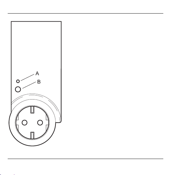
Housing
4
Length: 153 mm
Width: 63 mm
Height: 39 mm
(housing without plug)
A: Status display (green LED)
B: Button for manual operation and
Teach-in
Page 7
Teach-in
Teach-in
The new Hometronic components first have to be assigned to the
Hometronic Manager before they can be taken into operation. This
process is called the "Teach-in". The Hometronic Manager and the
new components exchange data during the procedure.
The socket switching module has a radio receiver
whose function can be impaired by metallic objects!
Caution!
► When selecting the operating site ensure that there is
sufficient distance to metallic objects, such as steel
reinforcements, metallic wallpaper, etc.
► Keep at least 30 cm distance from the next socket
switching module.
Connecting the switching module
► Plug the switching module into a socket.
The LED of the switching module flashes.
Activating the Teach-in mode at the switching module
Note: The Teach-in module remains active for a maximum of 4
minutes. Then the switch module changes automatically back to
normal mode.
5
Page 8
Teach-in
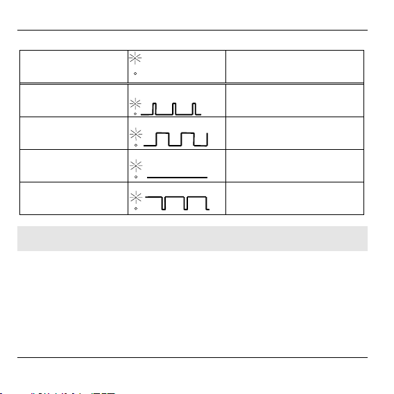
LED display during the Teach-in
Display
LED flashes rapidly Teach-in not carried out
LED flashes
LED off Teach-in successful
LED lights up green
with short breaks Teach-in failed
LED on
LED off
Status
Teach-in mode
(duration 4 minutes)
Note: The Teach-in mode can be aborted by pressing the button at
the switching module briefly.
► Keep the button pressed for about 10 seconds until the LED flashes
green evenly.
6
Page 9

Assignment to Hometronic Manager HCM 200
Switching to "Settings" submenu of Hometronic Manager
The Hometronic Manager is in automatic mode.
The display* at the Hometronic Manager
shows the standard display (example):
► Press the Dial button.
The cursor* flashes in the lowest line.
► Turn the Dial button to the right until
"Menu" is selected.
► Press the Dial button.
The following text is displayed:
► Turn the Dial button to the left until
"Settings" is selected.
► Press the Dial button.
The following text is displayed:
The Hometronic Manager is in the "Settings" submenu.
HOMETRONIC
WE 29.10.1999 11:15
No Lifestyle active
LIVING 20.0 C
HOMETRONIC
WE 29.10.1999 11:15
No Lifestyle active
LIVING 20.0 C
LIFESTYLE
TIME PROGRAMS
DISPLAY
SETTINGS
INSTALLATION
DE-INSTALLATION
FUNCTION EXTENSION
SENSOR FUNCTION
Teach-in
7
Page 10

Teach-in
Assigning socket switching module HS 20 to Hometronic
Manager as a device
► Change to the "Settings" submenu as on Page 7.
► Turn the Dial button to the until
"Settings" is selected.
► Press the Dial button.
The following text is displayed:
► Turn the Dial button to the left until
"Devices/Light" is selected.
The following text is displayed:
► Press the Dial button again.
The following text is displayed:
► Turn the Dial button to the left in order
to select the module which is to be
installed (in this case Module 2).
8
HEATING/COOLING
SHUTTERS
DEVICES/LIGHT
SENSOR
HEATING/COOLING
SHUTTERS
DEVICES/LIGHT
SENSOR
MODULE-1
MODULE-2
MODULE-3
MODULE-4
MODULE-1
MODULE-2
MODULE-3
MODULE-4
Page 11

Teach-in
► Press the Dial button.
An * is displayed after the selected
module (in this case Module 2).
► Activate Teach-in mode at the socket switching module within four
MODULE-1
MODULE-2 *
MODULE-3
MODULE-4
minutes (see Chapter "Activating the Teach-in mode at the switching
module on Page 5).
Installing socket switching module HS 20 to Hometronic
Manager as a collection relay
Example: Installing socket switching module HS 20 as a collection
relay.
► Activate Teach-in mode at the HS 20 as described on Page 5.
► Change to the "Settings" submenu as described on Page 7.
► Turn the Dial button to the left in order
to move the cursor to the "Settings"
submenu.
► Press the Dial button.
The following text is displayed:
► Turn the Dial button to the left until
"Boiler request" is selected.
HEATING/COOLING
SHUTTERS
DEVICES/LIGHT
SENSOR
SENSOR
SETPOINT ADJUSTER
ROOM CONTROL
BOILER REQUEST
9
Page 12

Teach-in
► Press the Dial button.
The following text is displayed:
SWITCHING MODULE
ANTI-FREEZE SENSOR
THERMOSTAT
► Turn the Dial button to the left until
"Thermostat" is selected.
► Press the Dial button.
An "*" appears after the "Thermostat"
entry. The device switch is assigned.
SWITCHING MODULE
ANTI-FREEZE SENSOR
THERMOSTAT
SWITCHING MODULE
ANTI-FREEZE SENSOR
THERMOSTAT *
The socket switching module HS 20 is installed as a collection relay.
Uninstalling collection relay
► Change to the "Settings" submenu (refer to Page 7).
► Turn the Dial button until "De-
Installation" is selected.
► Press the Dial button.
The following text is displayed:
► Turn the Dial button to the left until
"Boiler request" is selected.
HEATING/COOLING
SHUTTERS
DEVICES/LIGHT
SENSOR
SENSOR
SETPOINT ADJUSTER
ROOM CONTROL
BOILER REQUEST
10
Page 13

► Press the Dial button.
The following text is displayed:
Teach-in
SWITCHING MODULE *
ANTI-FREEZE SENSOR
THERMOSTAT *
► Turn the Dial button to the left until
"Thermostat" is selected.
► Press the Dial button.
The "*" after the "Thermostat" entry
disappears.
SWITCHING MODULE *
ANTI-FREEZE SENSOR
THERMOSTAT *
SWITCHING MODULE
ANTI-FREEZE SENSOR
THERMOSTAT
The collection relay is uninstalled.
Successful Teach-in
The Teach-in has been completed successfully when the flashing LED
at the switching module extinguishes.
A Teach-in only has to be carried out successfully once. If the socket
switching module is plugged into another socket or if the power fails,
no new Teach-in is required.
Note: The plugged-in device is always switched off after it has been
plugged in again or after the power supply has returned.
11
Page 14

Teach-in
Failed Teach-in
The Teach-in has failed when the LED at the switching module
flashes green with short interruptions. The data transfer per radio did
not take place or was faulty.
Note: Since the socket switching module tries to establish a con-
nection to the Hometronic Manager for the duration of 4 minutes, a
failed Teach-in is not displayed by the LED until after the 4 minutes
have passed.
► Carry out the following measures after a Teach-in has failed:
– Improve the data transfer
– Repeat the Teach-in
► Remove/avoid disturbing shielding devices, e.g.:
– Greater distance to a neighboring socket switching module
– Wireless headphones
– Garage door opener
– Remote controls
– Disturbing objects in the vicinity
– Metal parts
12
Page 15

Repeating the Teach-in
► Press the Dial button in order to
activate the Teach-in mode.
MODULE-1
MODULE-2 *
MODULE-3
MODULE-4
The module is activated again for teaching-in.
Teach-in
13
Page 16

Operation
Operation
Exceeding the maximum connected load* can destroy
the switching module.
Caution!
► Insert the device into the socket switching module.
Operating the socket switching module manually
In order to switch plugged-in devices on or off, press briefly on the
button of the socket switching module. The switching state is
displayed by the built-in LED.
• LED on = Device on
• LED off = Device off
Controlling the socket switching module with the
Hometronic Manager
Various operating modes of the socket switching module are possible
with the Hometronic. You can use the "Presence simulation" function
for example to repeat the operation course of the last 7 days. With the
"automatic brightness control" function, lamps or devices are
controlled via the brightness of an installed sun module HB 05/HB 15.
However, this operating mode only makes sense if, e.g. a lamp, radio
or similar devices are connected to the switching device.
For further information please read in the "Operation" chapter in the
Hometronic Manager instructions.
14
► Fuse the switching module with a maximum of 16 A.
Page 17

Operation
Device switch HS 20 as a collection relay of thermostat
control
A device switch HS 20 can be used (as a collection relay) for
feedback of the heat generation with thermostat control. The collection
relay switches the boiler on as soon as a relay in a zone under
thermostat control is activated.
For information on installing and setting the thermostat
control, refer to the operating instructions of the Hometronic
Manager HCM 200.
15
Page 18

Appendix
Appendix
Glossary
Connected load
Intake power of the plugged-in
device.
Presence simulation
The operation course of the last 7
days is repeated.
Cursor
Navigation symbol (flashing
rectangle) in the Hometronic
Manager display.
Display
Display window of the Hometronic
Manager.
Remote Control
Hometronic components can be
controlled with the HRD 20
Hometronic remote control.
16
LED
Light-emitting diode
Lifestyle
Combination of functions and
time programs which the
Hometronic sets in accordance
with a certain Lifestyle, e.g.
"Party" or "Holidays".
Module
Radio component of the
Hometronic system
Switchgear
Electrical devices such as lamps,
humidifiers, etc.
Teach-in
The process of assigning a radio
component to the Hometronic
Manager.
Page 19

Technical data
Operating voltage 230 V AC, 50 Hz
Intake power Approx. 1 W
Operating temperature 0...40 °C
Degree of protection IP 30
Storage temperature –20 °C...+70 °C
Maximum humidity 95 %, non-condensing
Limiting data of the connected load
Max. connected load at
Ambient temperature ≤ 30 °C
Ambient temperature > 30 °C
Approx. 3680 W, (230 VAC/16 A)
Approx. 2000 W,
(230 VAC/8.7 A)
Appendix
17
Page 20

Appendix
Information to the customer
After the Teach-in has been completed (in this case of the socket
switching module) the customer can be informed via the Hometronic
System:
► Familiarize the customer with the basic operation of the Hometronic
Manager.
► Explain the operation of the components on site.
► Also explain the possibilities of manual operation of the components
at the Hometronic Manager.
► If appropriate, point out any particular features and the possibilities of
extending the respective Hometronic Systems installed at the
customer.
Note: Please refer to the "Application" on Page 1.
18
Page 21

Help with problems
Problem/Display Cause Remedy
LED lights up green
with short breaks
No control by
Hometronic Manager
Plugged-in device is
switched on or off
automatically
Teach-in failed
Radio connection
is disturbed
(distance to the
next socket
switching module
is too small)
Time program,
Lifestyle or
presence
simulation is
activated
► See "Improving the
data transfer"
(Page 12).
► Repeat the Teach-in.
► Increase the distance
to the next socket
switching module
(ideally 50 cm)
► De-activate the time
program, Lifestyle or
presence simulation in
the Hometronic
Manager
Appendix
19
Page 22

Appendix
Notes
20
Page 23

Page 24

Honeywell AG
Böblinger Straße 17
D – 71101 Schönaich
Telephone (+49) 7031 637-300
This company is certificated to
The right is reserved to make modifications. This document is definitive for the
enclosed product and replaces all previous publications.
No. 7157519EN2H-0200 GE51R0802
 Loading...